
 Open Access Article
 This Open Access Article is licensed under a Creative Commons Attribution-Non Commercial 3.0 Unported Licence
Silane production from the dichlorosilane by-product of the Siemens process: a comparative study with the trichlorosilane route
Zi-Yi Chi†
 a,
Peng-Bo Bai†a,
Wen-De Xiaoa,
Ming-Dong Zhou*b and
Xue-Gang Li*a
a,
Peng-Bo Bai†a,
Wen-De Xiaoa,
Ming-Dong Zhou*b and
Xue-Gang Li*a
aDepartment of Chemical Engineering, Shanghai Jiao Tong University, 800 Dong-Chuan Road, Shanghai 200240, China. E-mail: xuegangli@sjtu.edu.cn
bCollege of Chemical Engineering, Shenyang University of Chemical Technology, Shenyang 110142, China. E-mail: mingdong.zhou@syuct.edu.cn
First published on 13th May 2025
Abstract
Silane (SiH4), a critical electronic specialty gas for semiconductor and renewable energy technologies, is conventionally produced via trichlorosilane (TCS) disproportionation. This study introduced an innovative route utilizing dichlorosilane (DCS), a by-product of the Siemens process, and comparative analysis was also conducted between the reactive distillation (RD) and fixed-bed reactor (FBR) approaches. Process simulations demonstrate that, given TCS as the feedstock and the same silane output, the RD approach reduces energy consumption to <25% of conventional FBR systems by overcoming thermodynamic equilibrium through continuous product removal. When employing the RD approach, the energy consumption using DCS as the feedstock can be reduced to approximately 35% or 22% of that when TCS is utilized, depending on whether the main by-product is silicon tetrachloride (STC) or TCS. This improvement stems from the superior thermodynamic and kinetic properties of DCS disproportionation. The optimal process configuration depends on whether the silane production process is integrated with the Siemens process or a grassroots facility.
Keywords: Silane; Dichlorosilane; Reactive distillation; Disproportionation; Process simulation.
1 Introduction
Silane plays a pivotal role in manufacturing semiconductors, display panels, photovoltaic cells, and next-generation silicon–carbon anodes for lithium-ion batteries.1–3 The photovoltaic industry currently leads as the predominant domain for silane application, utilizing it as a precursor in tandem with ammonia to form silicon nitride (SiNx) antireflection coatings on solar panels.4–6 With silicon's theoretical capacity exceeding graphite by 11-fold, silane-derived silicon–carbon anodes are poised to dominate future energy storage markets.7–10 This anode material, typically fabricated through silane CVD on porous carbon substrates, is anticipated to become the primary silane consumer, surpassing photovoltaic applications. Amidst the global drive towards carbon neutrality, the efficient and low-cost production technology for silane is imperative.Industrial silane production primarily employs the chlorosilane disproportionation process. Although other routes exist and some have even entered commercial production (e.g., the MEMC method involving silicon tetrafluoride reduction with alkali aluminum hydride), the chlorosilane route is favored due to its compatibility with the Siemens process for polysilicon production, mild operating conditions, and scalability.11–14 However, the chlorosilane disproportionation process suffers from low thermodynamic equilibrium conversion, which can be as low as 2% when trichlorosilane (TCS) is used as the starting material.15 Consequently, the conventional process originally developed by Jet Propulsion Laboratory (JPL)/Union Carbide Corporation (UCC) employs two fixed bed reactors (FBRs), necessitating energy-intensive material recirculation between reactors and distillation columns.16,17
In previous studies, we reported a reactive distillation (RD) process that overcomes the thermodynamic equilibrium of TCS disproportionation through continuous product removal from the reaction zone of the RD column, and nearly 100% TCS conversion could be achieved.14,18 On this basis, we commissioned China's first industrial electronic-grade silane production plant in 2014. Nevertheless, with TCS being the starting material, the RD column still consumes considerable energy, albeit significantly less than the FBR approach.
As discussed in our earlier work, the low thermodynamic equilibrium conversion of TCS disproportionation to silane is primarily caused by the first elementary reaction step, which involves TCS disproportionation to silicon tetrachloride (STC) and dichlorosilane (DCS).14,18 Both the rate and equilibrium constants of this reaction are much lower than those of subsequent DCS and monochlorosilane (MCS) disproportionation, suggesting that TCS is not a favorable starting material from both kinetic and thermodynamic perspectives.
DCS is an abundant by-product in the Siemens process for polysilicon production, generated during both the Si/STC co-hydrogenation and TCS reduction steps. The DCS concentration during TCS reduction must be rigorously maintained at minimal levels to prevent both product quality degradation and complications in tail gas treatment processes.19–21 Conventionally, it is converted back to TCS via a comproportionation reaction with STC, ultimately being converted to polysilicon.22
Based on the thermodynamic and kinetic analyses, we propose to use the DCS by-product as an alternative feedstock for silane production. To the best of our knowledge, this approach has not been reported in the literature. Besides higher reaction efficiency, the DCS route offers the option of modulating the disproportionation extent to generate TCS as the primary by-product instead of STC, establishing a seamless integration between silane and polysilicon production. The DCS disproportionation unit holds appeal for vertically integrated photovoltaic manufactures which consume both polysilicon and silane, compared to the conventional DCS/STC comproportionation unit.
As of now, there have been no literature reports comparing the cost of different silane production process routes. Considering that DCS is the by-product of the Siemens process, it is unrealistic to make an exact comparison of the material cost. Meanwhile, the atom efficiency of silicon is nearly 100%, thus the energy consumption, as the primary operational cost driver, is crucial to the total expenses of silane production.
To address this gap, the present study systematically evaluated the energy consumption of alternative silane production processes. Process models were established using the commercial package Aspen Plus in consideration of DCS and TCS feedstocks, and of FBR and RD routes. For comparative analysis, energy consumption metrics were normalized to uniform silane output rates following Chinese National Standard GB/T 50441-2016. Additionally, species mole fraction profiles and mole flowrate profiles along the RD column for different scenarios were presented to illustrate the operating behavior.
2 Results and discussion
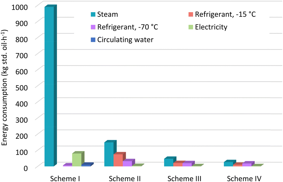
With the assumption of identical silane output rates, the total equivalent energy consumption of four schemes is shown in Fig. 1. Scheme I, the FBR-based TCS disproportionation, exhibits prohibitive energy consumption compared to the others. This is attributed to the low thermodynamic equilibrium conversion, resulting in extensive material circulation between columns and reactors, which imposes a significant separation load and energy consumption, particularly on columns T-TCS and T-DCS. In contrast, the RD-based processes break the thermodynamic equilibrium limit through continuous and in situ product removal, achieving high silane concentrations at the RD column overhead and significantly enhancing reaction efficiency. Consequently, the RD approach (scheme II) reduces energy consumption by 76.23% compared to the FBR approach (scheme I). | ||
| Fig. 1 Equivalent energy consumption of different process schemes. | ||
It is also evident from Fig. 1 that scheme III (RD-based DCS disproportionation with STC as the main by-product) further reduces energy consumption compared to scheme II, due to the thermodynamic and kinetic advantages of DCS disproportionation over TCS disproportionation. Fig. 2 plots the kinetic rate constants (ki) and the thermodynamic equilibrium constants (Ki) of reactions (1)–(3), respectively, against temperature. Kinetic parameters for calculating the rate constant are from the reference and based on the AMBERLYST A-21 catalyst.23 One can see that the reactivity of TCS disproportionation is the lowest while that of MCS disproportionation is the highest, and the impacts of kinetics and thermodynamics are synergetic. At a typical temperature of 80 °C, for DCS-related reactions the kinetic rate constants, k2 and k3, and thermodynamic equilibrium constants, K2 and K3, are 9.98 and 56.94 times, and 17.13 and 78.25 times greater than those for TCS disproportionation, k1 and K1, respectively, as shown in Fig. 2. This contributes to the substantial reduction in energy consumption for scheme III versus scheme II.
 | ||
| Fig. 2 Kinetic rate constants (a) and thermodynamic equilibrium constants (b) of reactions (1)–(3) against temperature. | ||
As shown in Fig. 1, when the DCS disproportionation is modulated to produce primarily TCS (scheme IV) instead of STC (scheme III), the unit energy consumption for silane production decreases by 62.15%. This is because the intermediate product TCS in scheme III inevitably undergoes the inefficient TCS disproportionation reaction, leading to higher energy consumption. However, scheme IV requires higher material consumption since the total reaction equation indicates that the material consumption of scheme IV is 1.5 times that of scheme III for the same silane output. The choice between these schemes depends on whether the silane production process is integrated with the Siemens process for polysilicon production. If so, scheme IV is preferable as the TCS by-product can be utilized for polysilicon production in the Siemens process, despite the higher material consumption.
Fig. 3 shows the breakdown of equivalent energy consumption for different utilities across the process schemes. Scheme I does not consume −15 °C refrigerant, while the RD-based schemes (II–IV) do not consume circulating water. The steam consumption of scheme I is overwhelmingly high, primarily due to the reboilers of columns T-TCS and T-DCS that are 377.19 and 570.28 kg std. oil per h, respectively, resulting from the low thermodynamic equilibrium conversion and substantial material circulation. In contrast, steam consumption in the RD-based schemes is significantly lower due to their superior reaction efficiency. The high steam consumption of scheme I also causes a large amount of circulating water consumption from the condensers of columns T-TCS and T-DCS. Notably, the RD-based schemes consume more refrigerant utilities, primarily from the intermediate and overhead condensers of the RD column. The variation in electricity consumption across the schemes is insignificant.
 | ||
| Fig. 3 Equivalent energy consumption breakdown of different process schemes. | ||
In addition to energy consumption, the feedstock material consumption emerges as another critical factor requiring rigorous evaluation in process assessment. It can be inferred from eqn (4)–(6) that the material consumption of the DCS route is less than that of the TCS route, and that would even change with the by-product species for the former. Given the uniform assumption in this work, scheme I and scheme II consume an identical TCS amount of 20.7 kmol h−1, and the conversion is calculated to be 96.20% for both, since the feedstock and the output materials are set to be identical. Scheme III and scheme IV consume DCS at rates of 10.1 and 14.6 kmol h−1, and the conversion is calculated to be 97.47% and 96.72%, respectively.
Since the by-product of the RD-based DCS disproportionation process can be manipulated by adjusting the operating parameters of the RD column, further analysis was made to assess the impact of the disproportionation extent (TCS/STC ratio in the RD bottom outflow) on energy and feedstock material consumption. Different scenarios were considered with the TCS molar concentration in the RD bottom outflow ranging from 1% to 95% as shown in Fig. 4. It is worth noting that the scenarios with TCS molar concentrations of 5% and 95% are identical to scheme III and IV, respectively, since the RD bottom outflow consists of almost nothing but the by-products TCS and STC. With appropriate design, the molar concentration of STC can be elevated above 99%, in other words, the molar concentration of TCS can be lowered below 1% at the expense of more energy consumption. However, the high purity of TCS is not realistic because inevitably the by-product STC will be generated yet cannot be discharged nowhere but from the RD bottom. Specifically for the current RD column configuration in this work, the molar concentration of TCS can be elevated up to 97% at the most. On the premise of the same silane output rate, equivalent energy and feedstock material consumptions exhibit an approximately linear decrease and increase, respectively, with increasing TCS concentration in the RD bottom outflow. The increase in material consumption is straightforward and can be calculated based on the reaction equations. The increase in energy consumption with decreasing TCS molar concentration, or the increase of STC molar concentration, in the RD bottom outflow can be ascribed to the lower reaction rate of DCS disproportionation to STC compared to TCS, necessitating a higher boil-up ratio at the RD column bottom.
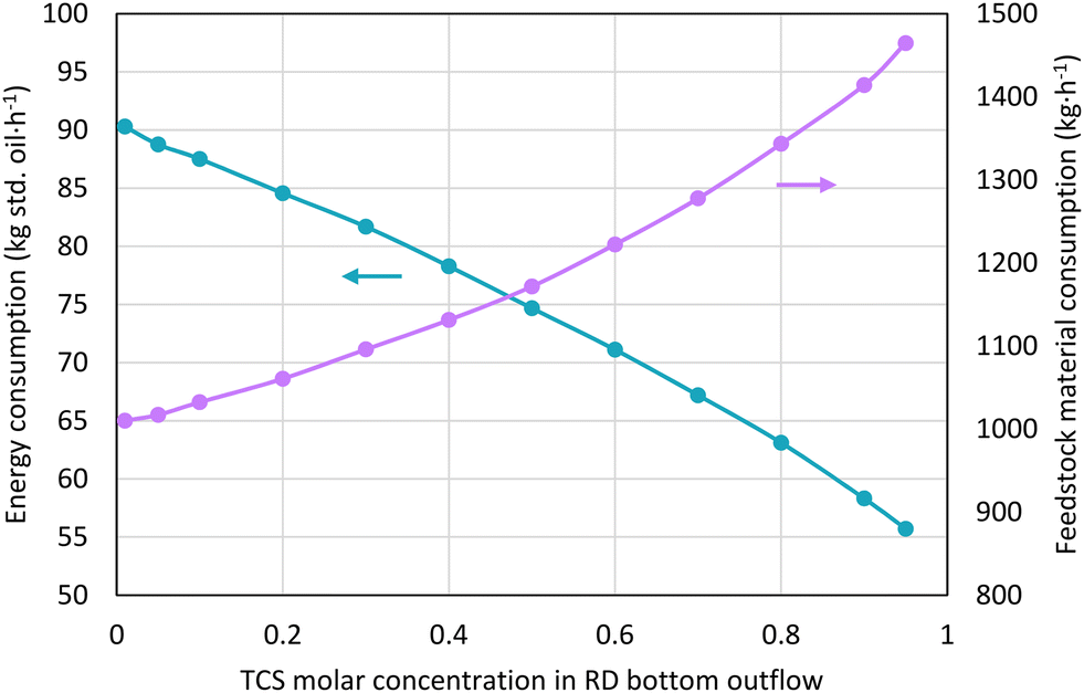 | ||
| Fig. 4 Equivalent energy and feedstock material consumptions with different TCS molar concentrations in the RD bottom outflow. | ||
The choice between schemes III and IV does not involve a black-and-white assessment. The appropriate scheme depends on whether the silane production process is integrated with the Siemens process for polysilicon production or operates as an independent unit. For integrated processes, scheme IV is preferred as the TCS by-product can be purified and used for polysilicon production in the Siemens process. For independent units with no TCS requirement, scheme III is preferable due to its lower feedstock material consumption and overall energy consumption that includes consumptions of the hydrogenation section.
For the purpose of conducting a comparative analysis of the operational performance, the profiles of species mole fractions in both vapor and liquid phases are presented in Fig. 5 and 6, respectively. It can be observed that for scheme IV, TCS is steadily enriched from the top of the reaction section to the upper portion of the stripping section. At most stage positions, the DCS mole fraction is predominant, particularly in the liquid phase, indicating that the DCS disproportionation constitutes the primary reaction and serves as the rate-limiting step within this system. In contrast, when the main by-product of DCS disproportionation is STC (scheme III), the mole fraction of DCS surpasses the mole fraction of TCS in the upper half of the reaction section, with a reversal of this trend occurring in the lower half. This corresponds to the DCS disproportionation to MCS and TCS, followed by the TCS disproportionation to DCS and STC.
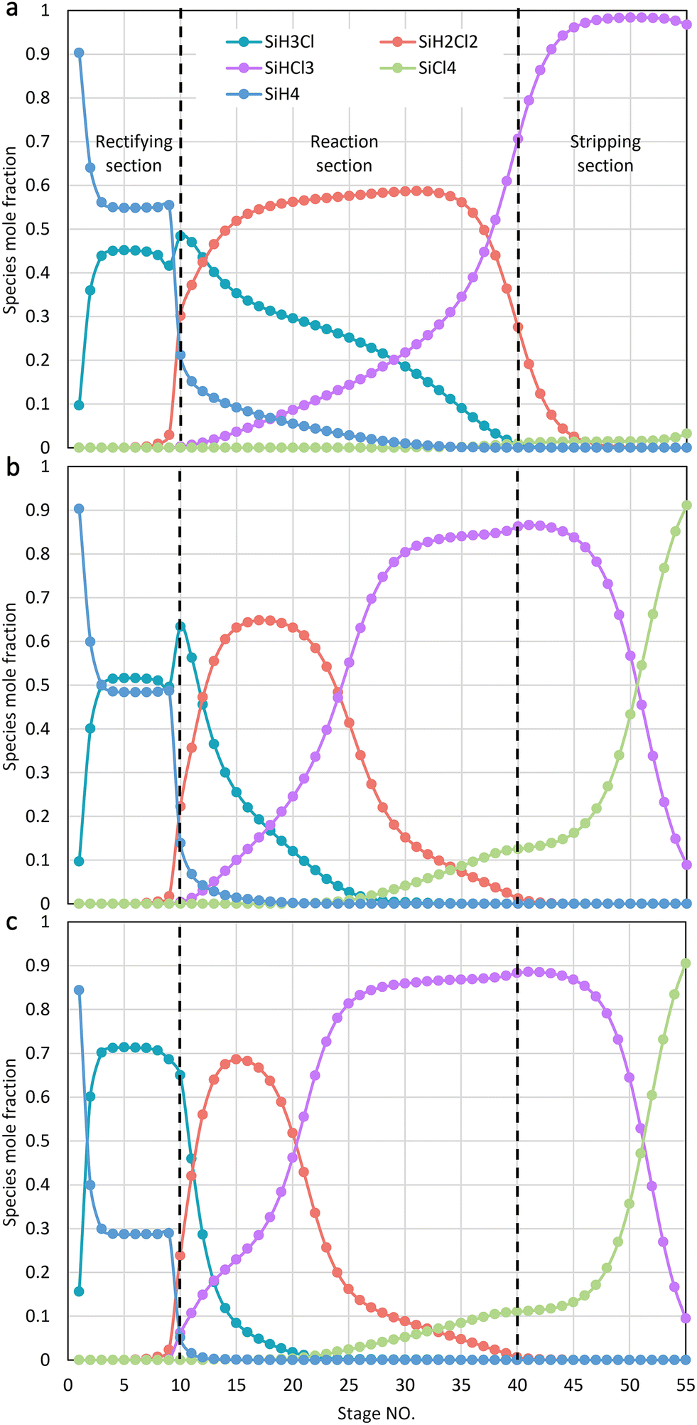 | ||
| Fig. 5 Species mole fraction profiles in the vapor phase. (a) Scheme IV; (b) scheme III; (c) scheme II. | ||
 | ||
| Fig. 6 Species mole fraction profiles in the liquid phase. (a) Scheme IV; (b) scheme III; (c) scheme II. | ||
A comparison between the species mole fraction profiles of scheme III and scheme II reveals a notable similarity, except for the fact that the TCS disproportionation in scheme II occupies a greater number of theoretical stages within the reaction section. This can be attributed to the use of TCS as the raw material in scheme II, which inevitably undergoes initial conversion to DCS before ultimately being transformed into silane. It is further observed that silane primarily exists in the vapor phase within the reaction section. This behavior is advantageous because the disproportionation reactions mainly take place in the liquid phase. The prompt transfer of silane from the liquid phase to the vapor phase helps break the thermodynamic equilibrium state of the reactions, thereby promoting a positive shift in the reaction equilibrium to generate more silane.
The mole flowrate in stages determines the dimension of the column. As shown in Fig. 7, given that the silane output rate is the same, the mole flowrates in the rectifying section are quite similar. In the reaction and stripping sections, however, the mole flowrate of scheme II is approximately four times greater than that of scheme IV. This outcome can be explained by the higher reaction efficiency of DCS disproportionation to silane compared to TCS disproportionation. The lower reaction efficiency of TCS disproportionation implies a greater circulation of intermediate materials between the reaction section and the column bottom. From this perspective, the use of DCS as a raw material helps reduce the capital investment required for the RD column.
 | ||
| Fig. 7 Flowrate profiles of vapor and liquid streams leaving each theoretical stage. | ||
Additionally, the mole flowrate of scheme III in the reaction and stripping sections exhibits slight increases compared to that of scheme II. This is also related to reaction efficiency, as scheme III involves another elementary reaction: the TCS disproportionation to STC and DCS. The kinetic rate of this reaction is significantly lower than that of DCS disproportionation. However, this increase is relatively minor and does not constitute a decisive factor in selecting the optimal scheme.
3 Conclusions
In summary, we proposed a novel route for silane production from the DCS by-product of the Siemens process. A detailed comparative analysis of energy consumption is conducted with the conventional TCS route, taking into consideration both FBR and RD approaches. The results indicate that the RD approach can significantly reduce energy consumption due to the continuous and in situ removal of products in the RD column, which breaks the thermodynamic equilibrium limit of the disproportionation reaction. Based on the RD approach, the DCS disproportionation route further reduces energy consumption by 65.61% or 78.41% compared to the TCS route, depending on whether TCS or STC is the primary by-product. The energy-saving effect is attributed to the thermodynamic and kinetic advantages of DCS disproportionation. The main by-product TCS necessitates higher feedstock material consumption, and the appropriate choice depends on whether the silane production process is integrated with a Siemens process for polysilicon production or operates as an independent unit. Furthermore, the DCS disproportionation route exhibits a substantial reduction in the mole flowrate within the reaction and stripping sections of the RD column, which contributes to decreased equipment size and fixed investment.4 Model development
4.1 Chemical reactions and the thermodynamic model
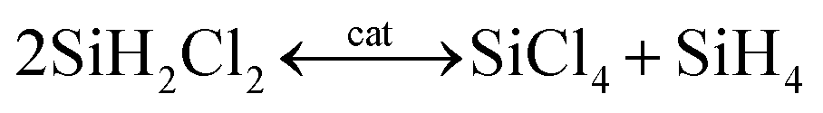
The fundamental chemical reactions for silane production from chlorosilanes, irrespective of TCS or DCS, involve three sequential and reversible elementary reactions, detailed as follows.18,23
 | (1) |
 | (2) |
 | (3) |
 | (4) |
 | (5) |
 | (6) |
The catalyst used in both processes can be the same, typically the bead-form weak base anion exchange resin. Therefore, the same set of chemical kinetic models that was used previously was employed in this study.14 The Peng–Robinson equation of state (PR EOS) in Aspen Plus was selected to perform thermodynamic calculation. Since binary interaction coefficients for chlorosilanes were unavailable in the Aspen Plus database, some were regressed from experimental vapor–liquid equilibrium (VLE) data found in the literature. For more details, one may refer to our earlier work.14,18
4.2 Conceptual process design
The main configuration of the RD unit is shown in Fig. 8a, comprising a stripping section, a reaction section, and a rectifying section, with accessory equipment including a bottom reboiler, an overhead condenser, and an intermediate condenser. To focus on the impact of reaction efficiency, a pure chlorosilane feedstock was assumed, omitting the practice of adding inert species of nitrogen to represent the volatile gas as done previously. This simplification allows omitting the light fraction removal column in the crude silane purification section. In practice, the stripping column is typically used during startup to remove purging gas and can be bypassed during normal operation. | ||
| Fig. 8 Reactive distillation (RD) based silane production process from chlorosilanes. (a) Main configuration of the RD column; (b) conceptual design for process simulation. | ||
The conceptual design for process simulation, shown in Fig. 8b, divides the RD column into two separate columns: T1-1 representing the reaction and stripping sections, and T1-2 representing the rectifying section. These columns are connected by an intermediate condenser unit (E102) comprising a heat exchanger, a gas–liquid separator, and a mixture that also receives recycled heavy fractions from the bottom of the product tower (T2).
The chlorosilane feedstock entrance is located between the rectifying and reaction sections of the RD column (top of T1-1 in Fig. 8b). Most specifications for the RD column were inherited from previous optimizations, except for the operating pressure, which was adjusted for the DCS route to ensure that the reaction section temperature remained within the catalyst's allowable range. The chlorosilane feed rate was adjusted to achieve a silane output rate of 160 kg h−1 for comparative simulations. Total conversion was controlled by specifying the chlorosilane by-product purity at the RD column bottom. Typical design specifications are listed in Table 1.
| Items | Specifications |
|---|---|
| T1-1 | |
| Operating pressure | 4.0–7.0 bar |
| Specification target | Bottom STC/TCS purity |
| Adjusted variable | Boil-up ratio |
| E102 | |
| Hot stream outlet temperature | 7 °C |
| T1-2 | |
| Operating pressure | 4.0–7.0 bar |
| Specification target | Overhead temperature: −40 °C |
| Adjusted variable | Reflux ratio |
| C101 | |
| Discharge pressure | 21 atm |
| E104 | |
| Hot stream outlet temperature | −40 °C |
| T2 | |
| Operating pressure | 20.0 bar |
| Specification target 1 | Overhead silane purity: 99.9999% |
| Specification target 2 | Overhead silane recovery: 99% |
| Adjusted variable 1 | Boil-up ratio |
| Adjusted variable 2 | Reflux ratio |
The FBR-based silane production process was also established for comparative purposes. As shown in Fig. 9, this process comprises two fixed bed reactors and four distillation columns, also known as the two-step-reaction process. The light fraction removal column was omitted due to the pure TCS feedstock, consistent with the RD-based process assumption. Notably, the single RD column (T1-1 and T1-2 in Fig. 1) in the RD-based process takes the place of the assembly of two reactors (R-TCS and R-DCS) and three columns (T-TCS, T-DCS, and T-SiH4) in the FBR-based process.
 | ||
| Fig. 9 Conventional fixed bed reactor (FBR) based silane production process. | ||
4.3 Process schemes for the case study
Based on the conceptual process design, the process models were established for four distinct schemes using the commercial package Aspen Plus. With TCS as the starting material, the FBR-based and RD-based processes were designated as scheme I and scheme II, respectively. When taking DCS as the starting material and RD as the reactor type, the main by-product could be manipulated to be either STC or TCS by adjusting the operating parameters of RD (e.g., the bottom temperature and/or the boil-up ratio), and the corresponding processes were designated as scheme III and scheme IV, respectively. Comparison among the schemes is shown in Table 2. In order to facilitate the comparative analysis on energy consumption, the same silane output rate of 160 kg h−1 was assumed for all schemes. It is worth mentioning that the process of scheme I was originally developed by JPL/UCC, which has long been the mainstream technical route for silane production.23 The process of scheme II was firstly proposed by the authors who led the construction of China's first commercial installation for electronic-grade silane production.14 The feasibility of scheme IV was also confirmed by the authors who led the construction of the world's first commercial installation for electronic-grade silane production from DCS.244.4 Total energy consumption calculation
Comparing energy consumption across chemical processes is often complex due to various types and grades of energies involved. In previous work, we used the two-factor utility cost equation developed by Ulrich and Vasudevan to estimate and compare utility costs among different scenarios.14,25 However, this method is complicated, requiring coefficients for each utility, the chemical engineering plant cost index (CE PCI), and fuel prices, which fluctuate frequently. In this study, another conversion method was adopted based on which all utilities were converted to standard oil with respective equivalent coefficients. These coefficients are specified according to a Chinese National Standard (standard for calculation of energy consumption in petrochemical engineering design, GB/T 50441-2016), except for −70 °C refrigerant, whose coefficient was estimated based on industrial data. While the prescribed coefficients may not fully align with operational realities in non-Chinese contexts, the normalized energy consumption values retain sufficient methodological rigor to support valid comparative analyses across different production systems.The specified equivalent coefficients of utilities used in this study are listed in Table 3. The effectiveness factor of heat exchange was specified to be 0.85 and 0.7 for steam and refrigerant, respectively. The compressor C101 was specified as a positive displacement compressor with a polytropic efficiency of 0.8 and a mechanical efficiency of 0.6. For the FBR-based process, the utility of circulating water was considered as the cooling medium for the overhead condenser of T-TCS and T-DCS columns.
| Blocks | Utility type | Unit | eQ,a kg std. oil | Annotations |
|---|---|---|---|---|
| a eQ represents the equivalent coefficient of primary energy consumption converted to standard oil quantity (kg std. oil). | ||||
| E101/E105 | 0.3 MPa-grade steam | t | 66 | 0.3 MPa ≤ P < 0.6 MPa |
| E102 | Refrigerant, −15 °C | MJ | 0.020 | Latent cooling |
| E103/E104/E106 | Refrigerant, −70 °C | MJ | 0.079 | Sensible cooling |
| C101 | Electricity | kW h | 0.22 | |
| FBR-based process involved | Circulating water | t | 0.06 | Sensible cooling |
Data availability
The data supporting this article have been included in the main manuscript.Conflicts of interest
There are no conflicts to declare.Acknowledgements
The authors thank the National Natural Science Foundation of China (No. 22378257) for supporting this work.References
- Y. Delannoy, Purification of silicon for photovoltaic applications, J. Cryst. Growth, 2012, 360, 61–67 CrossRef CAS.
- Z. Tang, X. Guo, H. Wang, H. Chen and W. Kang, A new metallization method of modified tannic acid photoresist patterning, Ind. Chem. Mater., 2024, 2, 284–288 RSC.
- A. Ohki, T. Ohmi, J. Date and T. Kijima, Highly purified silane gas for advanced silicon semiconductor devices, J. Electrochem. Soc., 1998, 145, 3560–3569 CrossRef CAS.
- Y. Sun, R. S. Rawat and Z. Chen, Mechanically robust anti-fingerprint coating on polycarbonate substrate, Appl. Surf. Sci., 2022, 597, 153706 CrossRef CAS.
- W. W. Hernández-Montero, A. Itzmoyotl-Toxqui and C. Zúñiga-Islas, Effect of thermodynamic parameters on properties of silicon-carbon films prepared by radio-frequency plasma-enhanced chemical vapor deposition for anti-reflective and photo-luminescent coatings, J. Vac. Sci. Technol., B, 2021, 39, 042203 CrossRef.
- Z. F. Mohd Ahir, A. R. Mohd Rais, N. Ahmad Ludin, K. Sopian and S. Sepeai, Exploring low temperature-sputtered indium tin oxide (ITO) as an anti-reflection layer for silicon solar cells, Semicond. Sci. Technol., 2024, 39, 115001 CrossRef CAS.
- Z. Cao, H. Sun, Y. Zhang, L. Yuan, Y. Liao, H. Ji, S. Hao, Z. Li, L. Qie and Y. Huang, Metallized polymer current collector as “stress acceptor” for stable micron-sized silicon anodes, J. Energy Chem., 2025, 101, 786–794 CrossRef CAS.
- L. Cao, M. Zheng, G. Dong, J. Xu, R. Xiao and T. Huang, Tailoring nanoscale primary silicon in laser powder bed fusion for high-performance lithium-ion battery anodes, J. Mater. Sci. Technol., 2025, 211, 278–287 CrossRef CAS.
- L. Zhang, C. Zhu, S. Yu, D. Ge and H. Zhou, Status and challenges facing representative anode materials for rechargeable lithium batteries, J. Energy Chem., 2022, 66, 260–294 CrossRef CAS.
- H. Wang, S. H. Lu, X. Wang, S. Xia and H. Beng Chew, A review of the multiscale mechanics of silicon electrodes in high-capacity lithium-ion batteries, J. Phys. D: Appl. Phys., 2022, 55, 063001 CrossRef CAS.
- E. M. Marlett, Process for production of silane, US Pat., 4632816, Ethyl Corporation, Richmond, Va, 1986 Search PubMed.
- A. D. Bulanov, P. G. Sennikov, A. Y. Sozin, A. Y. Lashkov and O. Y. Troshin, Formation of impurity Si2OH6 in silane synthesized from silicon tetrafluoride, Russ. J. Inorg. Chem., 2011, 56, 510–512 CrossRef CAS.
- A. Rasouli, R. Kuhn, S. Y. Lai, J. Safarian and G. Tranell, Silane gas production through hydrolysis of magnesium silicide by hydrochloric acid, J. Sustain. Metall., 2024, 10, 687–698 CrossRef.
- X.-G. Li, X. Huang and W.-D. Xiao, Reactive distillation-aided ultrapure silane production from trichlorosilane: Process simulation and optimization, Ind. Eng. Chem. Res., 2017, 56, 1731–1738 CrossRef CAS.
- Z.-P. Wang, C.-W. Liu, Z.-Y. Chi, J.-M. Yan, X.-G. Li and W.-D. Xiao, Catalytic disproportionation of trimethoxysilane to monosilane: Studies on catalyst, kinetics and reactor modeling, Chem. Eng. Sci., 2025, 302, 120826 CrossRef CAS.
- A. V. Vorotyntsev, A. N. Petukhov, T. S. Sazanova, V. I. Pryakhina, A. V. Nyuchev, K. V. Otvagina, A. N. Markov, M. E. Atlaskina, I. V. Vorotyntsev and V. M. Vorotyntsev, Imidazolium-based SILLPs as organocatalysts in silane production: Synthesis, characterization and catalytic activity, J. Catal., 2019, 375, 427–440 CrossRef CAS.
- J. Martinez-Gomez, C. Ramírez-Márquez, J. R. Alcántara-Ávila, J. G. Segovia-Hernández and J. M. Ponce-Ortega, Intensification for the silane production involving economic and safety objectives, Ind. Eng. Chem. Res., 2017, 56, 261–269 CrossRef CAS.
- X. Huang, W.-J. Ding, J.-M. Yan and W.-D. Xiao, Reactive distillation column for disproportionation of trichlorosilane to silane: Reducing refrigeration load with intermediate condensers, Ind. Eng. Chem. Res., 2013, 52, 6211–6220 CrossRef CAS.
- D. Zhao, Q. Zhang, F. Chen, X. Yuan, N. Yang, G. Xie, J. Wang, Y. Hou and B. Yang, A transport-kinetic model development for polysilicon chemical vapor deposition in a SiHCl3–H2 system, Int. J. Therm. Sci., 2024, 199, 108944 CrossRef CAS.
- Y. Hou, Z. Nie, G. Xie, W. Ma, Y. Dai and P. A. Ramachandran, Thermodynamic simulation of polycrystalline silicon chemical vapor deposition in Si-Cl-H system, Theor. Found. Chem. Eng., 2019, 53, 1048–1056 CrossRef.
- Y. M. Zhou, Y. Q. Hou, Z. F. Nie, G. Xie, W. H. Ma, Y. N. Dai and P. A. Ramachandran, Thermodynamic simulation of polysilicon production in Si-H-Cl system by modified Siemens process, J. Chem. Eng. Jpn., 2017, 50, 457–469 CrossRef CAS.
- D. Yan, in Handbook of photovoltaic silicon, ed. D. Yang, Springer Berlin, Heidelberg, 2019, pp. 37–68 Search PubMed.
- U. Carbide, Feasibility of The Silane Process for Producing Semiconductor Grade Silicon, 1979 Search PubMed.
- SJTU-SCCE, Prof Xuegang Li's team provides technology package for the world's first industrial DCS-based silane production plant, https://scce.sjtu.edu.cn/en/news/746.html.
- G. D. Ulrich and P. T. Vasudevan, How to estimate utility costs, Chem. Eng., 2006, 113, 66–69 Search PubMed.
Footnote |
| † These authors contributed equally to this work. |
| This journal is © Institute of Process Engineering of CAS 2025 |