
 Open Access Article
 This Open Access Article is licensed under a
 Creative Commons Attribution 3.0 Unported Licence
Tutorial on impedance and dielectric spectroscopy for single-cell characterisation on microfluidic platforms: theory, practice, and recent advances
Fatemeh
Dadkhah Tehrani
 ab,
Michael D.
O'Toole
*a and
David J.
Collins
b
ab,
Michael D.
O'Toole
*a and
David J.
Collins
b
aDepartment of Electrical and Electronic Engineering, The University of Manchester, Manchester, UK. E-mail: fatemeh.dadkhahtehrani@manchester.ac.uk; michael.otoole@manchester.ac.uk
bDepartment of Biomedical Engineering, The University of Melbourne, Melbourne, Victoria, Australia. E-mail: david.collins@unimelb.edu.au
First published on 14th February 2025
Abstract
Cell analysis plays an important role in disease diagnosis. However, many characterisation techniques are labour intensive, expensive and time-consuming. Impedance and dielectric spectroscopy (IDS) offers a new approach by using varying electrical current and electric field propagation responses to probe cell physiology. This review aims to explore the theoretical foundations, practical applications, and advancements in IDS for single-cell analysis, particularly when integrated with microfluidic technologies. It highlights recent developments in electrode configurations, calibration techniques, and data analysis methodologies, emphasising their importance in enhancing sensitivity and selectivity. The review identifies key trends, including the shift towards high-throughput and precise single-cell analysis, and discusses the challenges and potential solutions in this field. The implications of these findings suggest significant near-future advances in biomedical research, diagnostics, and therapeutic monitoring. This paper serves as a comprehensive reference for researchers in different fields to make a bridge between theoretical research and practical implementation in single-cell analysis.
 Fatemeh Dadkhah Tehrani | Fatemeh Dadkhah Tehrani received her B.Sc degree in biomedical engineering and M.Sc degree in tissue engineering from Amirkabir University of Technology in 2018 and 2021, respectively. She is currently undertaking a dual awarded PhD at The University of Manchester and The University of Melbourne. Her research focuses on developing sensors based on impedance and dielectric spectroscopy for single cell characterisation. Her research interests include biomedical studies, cell analysis, electrical characterisation, and sensors based on impedance and dielectric spectroscopy. |
 Michael D. O'Toole | Michael D. O'Toole received his M.Eng. (Hons.) degree in integrated engineering from the University of Reading in 2006, and PhD from the Wolfson School of Mechanical and Manufacturing Engineering, Loughborough University, in 2011. He was a Research Associate at The University of Manchester from 2011 to 2016 working primarily on magnetic induction systems for non-destructive inspection and characterisation. He was awarded a Leverhulme Trust Early Career Research Fellowship in 2016, and appointed lecturer in 2020. He is author and co-author of over 20 scientific publications and has recently filed his first patent. His research interests include signal processing, and sensor and instrumentation design, with a particular emphasis on magnetic induction systems for non-destructive testing. |
 David J. Collins | David J. Collins received his PhD from Monash University in 2015, for which he was awarded the Bill Melbourne Medal for best engineering thesis. He was subsequently a SUTD-MIT postdoctoral research fellow at the Singapore University of Technology and Design and the Massachusetts Institute of Technology from 2015–2018 before establishing the Collins BioMicrosystems Laboratory at the University of Melbourne in 2019. He was an ARC DECRA fellow from 2020–2022, and has published some 60 research articles across the domains of microfluidic devices, high-frequency acoustics and 3D additive manufacturing. |
1 Introduction
Biological samples collected from patients such as tissue biopsies, bodily fluids, and cells offer valuable insights into various medical conditions. Different aspects of a cell, from its membrane properties1 to its DNA sequence,2 hold information about its structure and function. These insights find applications in medical diagnosis, therapies, and regenerative medicine.3 While previous research often focused on aggregated cell populations,4 their complexity and heterogeneity have spurred interest in high-throughput techniques for precise single-cell analysis.Cell analysis methods include optical, mechanical, chemical, and electrical characterisation. Electrical methods, especially broadband impedance and dielectric spectroscopy (IDS), offer distinct advantages for non-invasive and real-time cell analysis.5 There are different terminologies given for techniques used for cell electrical characterisation, which are summarised in Table 1. Here, we define impedance spectroscopy as the measurement of a sample's opposition to a varying current at different frequencies, often obtaining bulk properties such as sample conductance and capacitance. The term is commonly used in low-frequency measurement (up to a few MHz) where lumped-element modelling assumptions are valid. Dielectric spectroscopy is a form of impedance spectroscopy where material-specific properties are analysed, such as conductivity and permittivity. The term is more common in studies measuring at higher frequencies (a few MHz to GHz) where transmission line assumptions prevail.
| Technique | Principle | Applications | Advantages | Limitations | Ref. |
|---|---|---|---|---|---|
| Electric IDS | Analysing bulk sample properties in a stationary mode | Tissue analysis, 3D cell culture analysis | Comprehensive spectral information | Low throughput | 6, 7 |
| Electric flow IDS | Single cell analysis when cells are passing through a microfluidic channel crossing the sensing zone | Analysis of live/dead cells, identifying cell subpopulations, blood analysis | High throughput and real time | Limited to few frequency points | 7, 8 |
| Electric cell substrate IDS | Analysis of cells attached to the surface of electrodes | Investigation of cell adhesion, proliferation, and migration, monitoring the effect of drugs | Sensitive to cell properties, dynamic characterisation of cells | Limited to substrate adherent cells, medium throughput | 9 |
| Electrorotation | Analysis of cell rotation when torque is induced by a rotating electric field | Cell membrane and cytoplasm characterisation, cell organelle evaluation | Detailed analysis of cell properties | Precise control of the electric field, time sensitive | 10, 11 |
In cell studies, IDS reveals electrical properties of cell components by exposing cells to electromagnetic fields, which induce changes based on the frequency-dependent behavior of cell membranes, organelles, and structures. IDS can analyse cells without modifications or labelling,12 making it suitable for high-throughput analysis and rapid profiling of cell populations down to the single-cell level. Its real-time monitoring capability allows dynamic observation of cell responses to stimuli.13 IDS has been widely used in macro-scale systems, analysing blood dielectric properties14 and tissue electrical properties to support diagnosis.15 Commercial products such as Coulter counters (Beckman Coulter Life Sciences, USA) and impedance-based flow cytometry (e.g., BactoBox®) are employed for cell analysis16 and enumeration,17 despite calibration challenges. The integration of IDS with microfluidics has broadened its applications by improving analysis precision by reducing sample volume. Miniaturising IDS in microfluidic environments has enabled activities ranging from precise DNA analysis2 to advancements in tissue engineering.3 While IDS has proven useful for single-cell analysis, its sensitivity to minute changes in cell properties presents challenges. Current efforts aim to enhance sensitivity, selectivity, and cell handling by integrating IDS with sophisticated microfluidic setups, automated systems, advanced data analysis, and specialised electrode designs.
A number of reviews have explored the multifaceted applications of electromagnetic waves for cell characterisation. These reviews span theoretical foundations,18 practical applications,19 data analysis techniques,20 static and dynamic cell analysis,21,22 and electrode configurations,23,24 as well as challenges in bioimpedance devices,24 impedance and microwave sensing methods, position-dependent signals,25 cell analysis across the electromagnetic spectrum,26 and application of machine learning in impedance data analysis.27–29 Given the recent interest in this interdisciplinary field, and its application in various fields of study, this review aims to examine the theory, techniques, designs, and applications of IDS on microfluidic systems, with a special focus on biological and cell studies. In particular, we investigate broadband (kHz–GHz) IDS setups and include insights into calibration techniques, diverse sample handling strategies, and effective data analysis methodologies. Accordingly, this work serves as a reference across fields such as biology, biotechnology, pharmacology and medicine as well as electrical engineering by offering a fundamental understanding of how electromagnetic fields can be leveraged to analyse biological samples at the single-cell level. This accordingly facilitates the advancement of research and practical applications in these domains, bridging the gap between theoretical research and practical implementation.
2 Impedance and dielectric spectroscopy theory
Dielectric materials polarise in a frequency-dependent process when exposed to an electric field. This results in charge displacement, energy dissipation and formation of responses, dictated by the material's composition and structure. These responses, depicted in Fig. 1, include ionic displacement (ionic polarisation), resistance to charge movement across interfaces (interfacial or Maxwell–Wagner polarisation), polar molecule reorientation (dipolar polarisation), atomic stretching (atomic polarisation), and electron displacement (electronic polarisation). This collective frequency dependent behavior of the material forms its dielectric dispersion. | ||
| Fig. 1 Variation of dielectric ε′ and ε′′ as a function of frequency and its relevance to biological phenomena in a single cell. | ||
The relaxation frequency of each of these mechanisms is marked by a drop in the real part of permittivity (ε′) and a peak in its imaginary part (ε′′). For example, at low and medium frequencies (LF–MF), ionic polarisation is dominant. However, at higher frequencies the electric field rate of change becomes faster than the process of ionic polarisation. As a result, the contribution of this phenomenon to the sample's permittivity diminishes and a part of the electric energy dissipates as heat. The frequency at which this shift happens is the relaxation frequency of the polarisation.
Dielectric polarisation begins to decay as soon as the electric field is removed, which can be captured by the relaxation function. The relationship between the complex permittivity (ε*(ω)) and the relaxation function is established using linear transfer function. For instance, the Debye relaxation function, represented in Fig. 2A, is a specific case of this with the assumption of a single relaxation time (non-interacting dipoles). Addressing the limitations of the Debye model and giving a complete description of dielectric properties, more complex empirical relations have been developed such as the Havriliak–Negami and general models given in Fig. 2A, accommodating conductivity and multiple relaxation times. The general relaxation function of complex systems with a fractal structure with diverse dielectric behaviours can be represented by a constant phase element (CPE).30
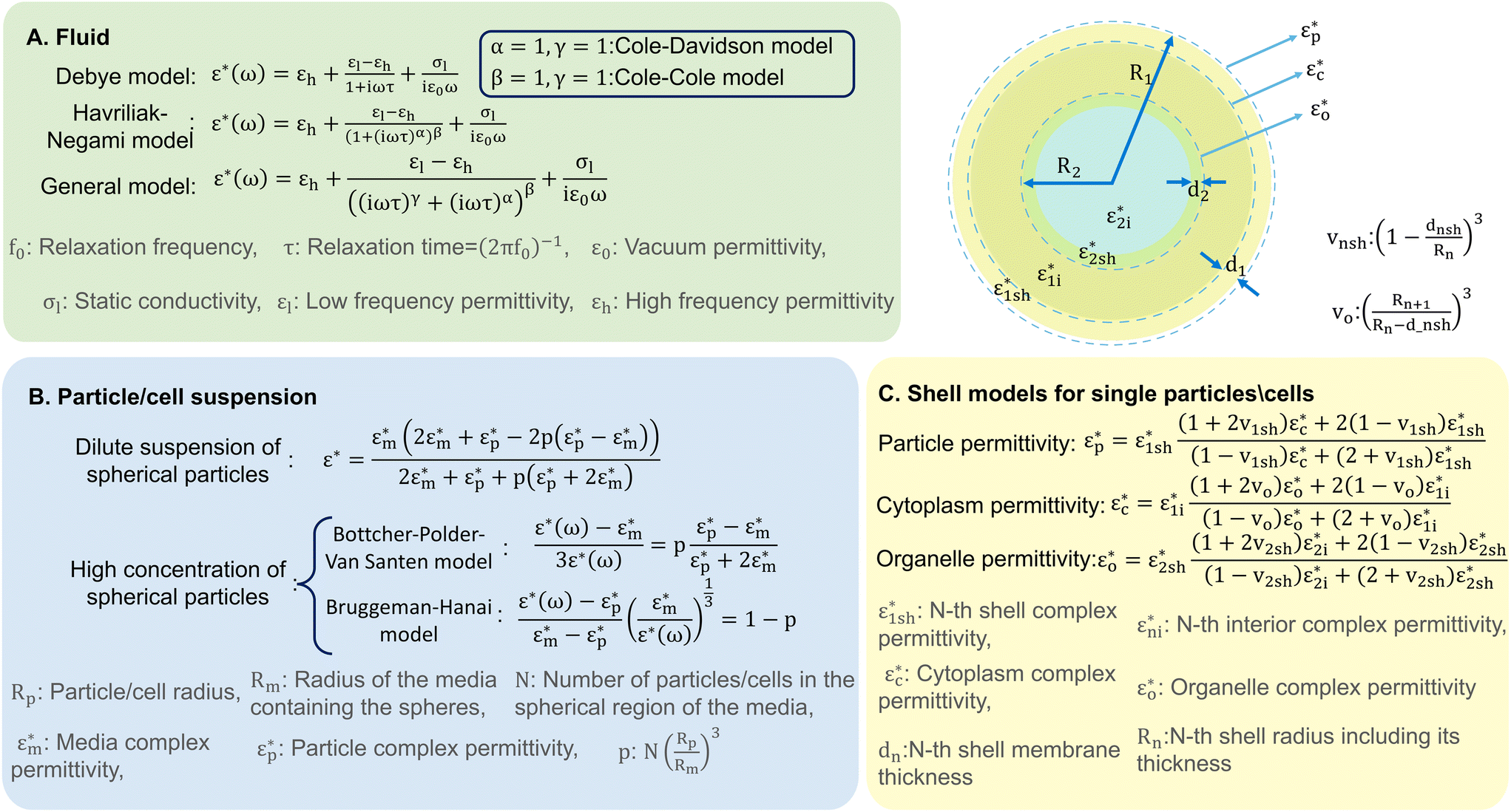 | ||
| Fig. 2 A graphical representation depicting various analytical models developed for analysing A) liquids, B) particle or cell suspensions in liquids, and C) single cells or particles in a liquid. | ||
The dielectric dispersion of a cell over a frequency range of Hz–GHz can be grouped into three regions: α, β, and γ-dispersions, depicted in Fig. 1, with some references defining another dispersion (δ) in between β and γ.18 These dispersions provide unique insights into cell properties, as summarised in Table 2. For example, while lower frequencies are usually used to analyse cell size, membrane properties, and quantify cell concentration, higher frequencies can provide information on inner cell properties and organelles, cytoplasm composition, and cellular pathophysiology. Characterising cells using these dispersions necessitates isolating the responses generated solely by the cell, identifying each polarisation mechanism it undergoes, and discerning the cause of impedance changes across different cell types.30
| Dispersion | Frequency range | Phenomena | Dominant mechanism | Relevance | Ref. |
|---|---|---|---|---|---|
| α | Hz–kHz | Ionic diffusion at cell membrane, biological processes within cells | Counterion polarisation | Cell presence and enumeration | 18, 30 |
| β | kHz–MHz | Cell membrane and organelle membrane properties | Interfacial polarisation | Cell shape and membrane integrity | 18, 30 |
| δ | MHz–GHz | Polarisation of bound water, amino acids, and proteins | Dipolar relaxation | Changes in cell nucleus | 9, 18 |
| γ | >GHz | Free water polarisation | Atomic polarisation | Cytoplasmic changes | 18 |
This can be accomplished using analytical models originally developed for capacitors with diverse dielectric layers and have been extended to include suspended spheres and colloidal systems, similar to cell suspensions.31 Spherical variations of these models are summarised in Fig. 2B.30 Wagner's theory provides a model for the complex permittivity of dilute suspensions, while the Bottcher–Polder–Van Santen and Brummagem–Hanai models accommodate higher particle concentrations using effective medium theory. However, these models become complex for single practical analysis, often requiring numerical methods for accuracy.
The shell model,30 depicted in Fig. 2C, can be used for single particle/cell analysis. It is based on Maxwell–Wagner theory and represents a particle surrounded by a thin, insulating membrane. The complex permittivity of the system is determined by the permittivity of both the shell and the particle interior. This approach is iterative, allowing for the development of more realistic models of cell structure by adding multiple shells to represent various inner organelles, each enclosed in its own resistive membrane. This theoretical groundwork on the interaction of electromagnetic waves with cells sets the stage for detailed exploration of these techniques' working principles, which we examine in subsequent discussion.
3 Applications of impedance and dielectric spectroscopy in on-chip cell characterisation
IDS techniques offer valuable insights into cell size and the electrical properties of its membrane, cytoplasm, and inner organelles. These insights provide an opportunity to assess cell health, viability, differentiation, and behaviours. This review examines their applications in biology and medicine, including tasks such as cell counting, sizing, and discrimination based on size, deformation, and intrinsic properties, along with analysing cell responses to stimuli.At low frequencies, IDS usually discriminates cells based on their size. Cell size analysis is a common practice in biological studies, though traditional methods such as optical microscopy and imaging flow cytometry32 suffer from sensitivity to alignment and experimental conditions.33 IDS has been successfully used for: differentiation of live, apoptotic, and necrotic cells,34 and circulating tumour cells with larger size and increased membrane capacitance compared to other blood cells;35 profiling monocyte and leukocyte activation in type II diabetes, correlating leukocyte size and opacity with cardiovascular risk factors;36 demonstrating neutrophil functional traps in glucose-treated neutrophils for diabetes testing;37 distinguishing activated T-lymphocytes;38 and analysis of the success rate of cell sorting.39 Additionally, changes in cell size during mitosis phases have been shown to correlate with impedance signals.40 However, current IDS setups lack standardised particles with controlled electrical traits, crucial for benchmarking unknown cells using common techniques such as flow cytometry. This is an active field of research aimed at increasing the application of IDS in cell-based size discrimination.41 Furthermore, IDS has recently been employed to optimise the frequency of positive dielectrophoresis based on the cell's biophysical characteristics, improving sorting efficiency of circulating cancer cells.42
Moreover, IDS can be used for cell counting as it has been shown that changes in sensing zone capacitance directly correlate with cell quantity.43 Recent improvements in integrating neural networks with impedance cytometry have enabled the capture of single-cell signals hidden in the measured signals from cells simultaneously passing through the sensing zone.44 This can offer cost-effective alternatives to complex sample preparation steps used in conventional techniques. When IDS is performed at frequencies higher than 1 MHz, cells can be categorised based on their intrinsic (i.e. cytoplasm) electrical properties.45 Data provided by this analysis can be used to distinguish live and dead cells46 with applications in food safety47 and medicine.48
Building on this, addition of a microfluidic method to induce cell deformation can make this technique applicable in understanding cellular states and diseases which are reflected in their deformability. Common techniques used for cell deformability analysis are atomic force microscopy and micro-pipette aspiration, offering insights into cytoskeletal structure in a low-throughput manner. IDS can provide a high-throughput alternative with the benefit of simultaneous mechanical and electrical analysis of cells.49 Cell deformation is induced in these systems by constricted channels50 or extensional flow,51 permitting contactless operation. Cell deformation can be then translated into size-independent parameters such as cytoplasmic viscosity, capacitance, and membrane tension,52 which can then be used to differentiate cell populations.53 For instance, specific membrane capacitance and cytoplasmic conductivity can be used to classify sub-types of tumor cells after genotypical or phenotypical modifications.54 Information gathered on cell deformation, diameter, and electrical properties has further been used to distinguish leukocyte and granulocyte sub-types.55
The application of IDS in classifying cells based on their intrinsic electrical properties, size, shape, and deformability has introduced a new non-invasive approach for studying cellular responses to various stimuli, offering an alternative to conventional methods.3 While traditional methods such as fluorescent labelling for cell imaging, flow cytometry, and RNA and DNA sequencing are precise, they often require specialized techniques, compounds, and instruments for sample preparation and analysis. Moreover, their invasive nature renders tested samples unusable for further research. Recently a study56 has analysed the effectiveness of measuring electrical deformability of cell shape after mechanically inducing shear stress by comparing the results to optical deformability measurements using a custom made setup, reaching a very high correlation between the two methods.
IDS has been utilised to investigate the effect of chemical57 and physical58 treatments on cell viability as well as analysis of the reversible electroporation efficiency.59 IDS has also been used in analysing the results of antimicrobial susceptibility testing60 and analysis of host microbiota susceptibility after antibiotic treatments.61 Another study observed changes in RBCs infected by P. falciparum over time,62 leveraging a multi-shell model to note variations in membrane capacitance, cytoplasmic conductivity, and parasite volume ratio at different infection stages. These findings could aid in distinguishing infected and uninfected cells, potentially benefiting disease diagnostics. While low frequency measurements are sufficient in most of these studies, the cell membrane acts as a barrier, eliminating wave propagation through cell cytoplasm. As a result, most of these studies take into account cell size variations and membrane properties as a feature for differentiation and characterisation of cells.
At higher frequencies, the capacitive barrier produced by the cell membrane can be bypassed, providing insights into the cell's cytoplasm and organelle properties. For instance, analysis of the reflected and transmitted signals enables evaluation of mitochondrial activity63 and nucleus size8 with applications in cell differentiation based on normal, shrunk, or enlarged nuclei detected through changes in cytoplasm capacitance.64 While this evolving field holds promise in understanding cell behaviour and responses to stimuli and can pave the way for more effective diagnostics and targeted therapies, studies in this domain remain limited. The variations in signal amplitude and phase induced by changes in intracellular properties, such as nucleus size, are often subtle, requiring very sensitive setups as well as sophisticated models to establish correlations between these variations and biological characteristics. With the development of advanced techniques with a higher signal-to-noise ratio (SNR) and integration of machine learning techniques, further advancements may be realised. These innovations could enable a more detailed analysis of intracellular properties, including nucleus characteristics, expanding the application of broadband IDS in cellular diagnostics and therapeutics.
Recent advancements in neural networks and deep learning offer a potential contribution to IDS, particularly in rapid cell assessment and classification.65 These methods have shown success in low frequency analysis, where impedance data has been used to classify cells based on size-independent electrical properties,66 mechano-electrical properties,52 and cell deformability67 resulting in applications such as five-part leukocyte differentiation.68 While the majority of studies integrating machine learning techniques with single-cell IDS have focused on low frequency studies, recent studies have explored higher broadband frequency analysis.
In broadband studies, for example, prediction models have been developed to differentiate the permittivity of two species of viable and nonviable yeast cells at frequencies most sensitive to the difference of live/dead cells.69 Moreover, analysis of the entire spectra in the range of MHz–GHz using machine learning algorithms has enabled the evaluation of the chemical treatment effects on cell nucleus size,64 and to detect various bacterial species in a high throughput setup.70 These advancements highlight the potential of the integration of machine learning with IDS to take advantage of the cellular information captured across a wide frequency range.
In summary, IDS offers a promising alternative to slow, costly, and/or low efficacy techniques that impact samples irreversibly and require large cell quantities. Their integration with optical methods enhances understanding of how cell phenotype correlates with impedance signals.71 Some studies propose approaches that merge cell sorting with impedance measurement compartments, creating a sample-in-answer-out platform for blood cell phenotyping.36,38 Exploring the optimal frequency to distinguish between cell types is also an intriguing avenue.72
4 Setup development
4.1 Instrumentation
The essential elements of an IDS for biological studies are frequency domain spectrometers and sensing units which are demonstrated in Fig. 3. The frequency spectrometer outputs an oscillating waveform typically stepping through one frequency at a time and compares this against one or more response waveforms measured synchronously with the output. The spectrometer then returns a demodulated result at each frequency, i.e. the phase and amplitude change from output to input or between inputs. Over a bandwidth spanning the RF and microwave regimes, network analysers are utilised, measuring the complex reflection (S22, S11) and transmission (S21, S12) parameters of a material-under-test (MUT). A scalar network analyser returns the magnitude of these parameters, whereas a vector network analyser (VNA) returns both the magnitude and phase. In studies involving low frequencies (Hz–MHz), an impedance analyser or its equivalent such as a lock-in amplifier applies a sinusoidal potential to the electrodes, measuring the current with respect to the applied voltage. This analysis yields the complex impedance, derived as the ratio between the excitation voltage and the response current. Both these setups should apply a low power to ensure cell integrity.73 Recent work has further used on-chip waveform generators and lock-in amplifiers to replace bulk lab instrumentation, enabling the development of wearable and implantable devices.74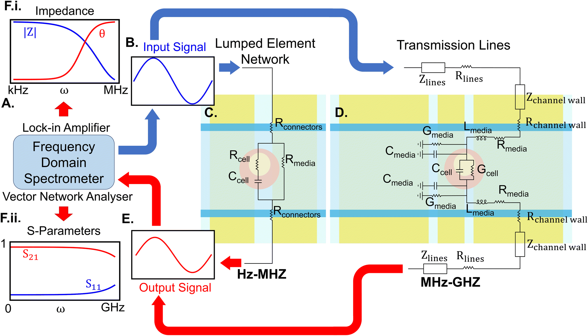 | ||
| Fig. 3 Essential elements of an IDS for single-cell studies. A) A frequency domain spectrometer, which can be a lock-in amplifier or an impedance analyser suitable for low-frequency analysis or a VNA suitable for broadband measurements. B) This instrument inputs a signal with a predefined voltage to the sensor. C) The sensor may be designed for low-frequency analysis, where its components are modelled as lumped elements, D) or for high and broadband frequency analysis, where the electrodes are modelled as transmission lines. E) The output signal is transmitted back to the spectrometer, where the data is represented as either the magnitude and phase of impedance (F.i) for low frequencies, or S-parameters (F.ii) for high frequencies. | ||
The sensing unit commonly consists of sets of electrodes positioned around a channel or a cavity containing the MUT. The connection between the frequency spectrometer and the sensing unit requires careful consideration of transmission and parasitic effects, necessitating precise calibration. For example, microwave probes, though preferred for GHz measurement at the micro-scale,75 are more prone to parasitic effects and necessitate additional calibration.76 Sensing units can either be developed on integrated on-chip setups77 or printed circuit boards (PCBs) integrated with microfluidics.78 Although cost-effective, PCB-based methods may nevertheless suffer from reduced sensitivity, necessitate additional steps for bio-compatibility and efficient fluid control, and are not transparent. Transparency enables the integration of these setups with microscopes for live measurements.
At frequencies up to a few MHz, electrode structures effectively operate as lumped element networks. However, at higher frequencies where electrical lengths become significant, they can be considered as transmission lines (TLs). At these frequencies, sensors can be broadly categorised into broad and narrow-band. Broadband sensors use planar transmission lines and waveguides, such as microstrip lines, slot lines, and coplanar waveguides (CPW), to observe dielectric changes across a wide range of frequencies. Narrow-band techniques leverage these structures to form resonators to scrutinize dielectric responses at specific frequencies with higher precision.
The performance of broadband platforms is limited by noise from high-loss passive components, reduced SNR near the water relaxation frequency, and lack of a single calibration technique across a wide frequency range (Hz–GHz).79 To overcome these challenges, complementary metal-oxide semiconductor (CMOS) technology has been integrated into these setups,80 forming interferometric systems,81 oscillator sensors,82 and micro-electrode arrays with application in high throughput enumeration of cells with a single cell resolution.74
By contrast, narrow-band resonators avoid these limitations by focusing on a small number of discrete frequencies. The MUT flowing through a microfluidic channel atop a resonator disturbs the fringing field, altering its capacitance, influencing resonant frequency, and quality (Q) factor. Measuring S parameters at resonance occurs in a shorter time compared to broad-band measurements.83 These changes, translatable through equivalent circuit models (ECMs), reflect the sample's electrical properties within the channel.84 For instance, it has been shown that frequency shifts in resonance are proportional to cell volume and inversely related to sensor volume.26 However, oscillator stability remains challenging, demanding noise cancellation methods for accurate measurement due to a variable and degrading Q-factor.85
4.2 Design and fabrication
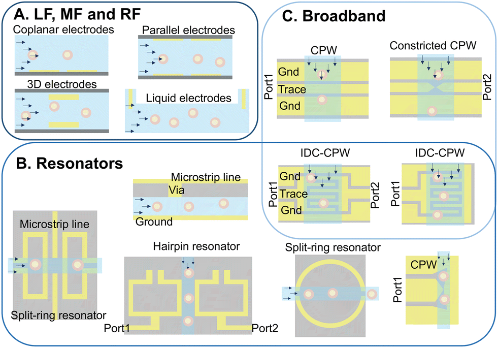 | ||
| Fig. 4 Examples of different electrode configurations used in IDS cell characterisation at low frequency (kHz–MHz) (A), broadband (kHz–GHz) (B) and narrow-band (GHz) (C) setups. Cells can be suspended or cultured in the sensing area, however, here they are flowing through the channels. | ||
Low frequency configurations. Common low-frequency electrode designs include coplanar, parallel, liquid electrodes, and micro-electrode array configurations, as depicted in Fig. 4A. Coplanar designs, featuring two or more electrodes in a single plane on one side of the channel, have been extensively employed for cell type analysis,86 drug exposure tests,87 and mechano-electrical cell property studies through integration with constricted channels49 or hydrodynamic pinching.88 Despite the ease of fabrication, this configuration produces an inhomogeneous electric field confounding responses with the cell's vertical position as well as electrical properties. Moreover, meaningful data extraction requires extensive post-processing, limiting applicability to unlabeled cell populations.24 Increasing the number of electrodes has been shown to enhance information extraction, including particle velocity, electrical diameter, and relative prominence, correlating with particle height from the signal.89 Micro-electrode arrays, a subgroup of coplanar electrodes, feature tens to thousands of electrodes on a single surface, each typically analysing a single attached or trapped cell with high precision.74
Parallel electrode configurations feature the use of electrodes on the top and bottom of the channel. These have been used for cell differentiation90 and tumorigenicity assessment.12 Novel configurations have been used to improve sensitivity, including differential measurement setups to reduce background noise91 and resonant circuits with series inductors to enhance response current by reducing impedance at resonance frequency.92 Despite challenging multi-step fabrication requiring precise alignment, these setups generate more homogeneous electric fields. Solid 3D electrodes, however, offer simpler fabrication, achieved by inserting tungsten needles93 into the main microchannel. This comes at the expense of relatively large dimensions, which negatively impact sensitivity for single-cell studies. Enhanced accuracy with uniform electric fields over a small volume can be attained by reducing electrode size with probing gates that are aligned to the flow direction, and can be made with monocrystalline silicon and supported by passive SU-8 pillars.94 Facilitating fabrication, heavily doped silicon wafers integrated with readily aligned sidewall micro-electrodes95 or silver–PDMS96 and carbon–PDMS97 setups eliminate sacrificial layer lithography, reducing costs. Alternatively, liquid electrodes utilise conductive liquids to carry current generated at side chambers by coplanar electrodes or prefabricated electrode channels filled with low-melt-point alloys.98 This simplifies fabrication and ensures a homogeneous electric field while nullifying the dominating effect of electrode–electrolyte interface capacitance, making this approach suitable for low-frequency and high-throughput cell shape and deformation analysis.99
These electrodes are crucial components in commercial Coulter counters, which involve two chambers connected by an orifice and filled with conductive liquids. These systems have been modified into high-throughput on-chip setups,100 measuring resistance changes when cells displace the liquid passing through the orifice. However, flow instability affects performance.24 Combining liquid electrodes with other configurations such as coplanar101 and parallel electrodes65 can also be used to compensate for fringing effects with a more homogeneous electric field. Integration with dielectrophoresis (DEP) focusing further enhances signal consistency99 and reduces signal dependency on cell position.66 DEP focusing exploits electrokinetic phenomena, directing polarisable particles to specific vertical positions in an inhomogeneous electric field. Finally, applying an electric field perpendicular to constricted channels using liquid electrodes enables high-throughput single-cell analysis with reduced current leakage.66
High frequency configurations. Electrode configurations for resonators and broadband setups are depicted in Fig. 4B and C, respectively. Resonator electrodes are categorised into 3D and planar configurations. 3D electrodes encompass coupled double split-ring and cylindrical dielectric resonators,83 substrate-integrated waveguide cavity resonators,102 and folded-waveguide cavities.103 While 3D electrodes offer improved sensitivity, planar electrodes are more compact, suitable for integrated platforms, and readily compatible with lab-on-chip technologies. However, they may exhibit reduced sensitivity due to lower-quality resonance and smaller fringing electric fields. Efforts are underway to overcome these limitations.84,104 Designing resonator electrodes for cell studies with a suitable Q factor and sensitivity requires knowledge of the specific frequencies exciting cell properties at the scale of interest.105
Planar transmission lines, particularly the coplanar waveguide (CPW) structure, are widely employed for developing broadband sensors, and are effective in cell analysis up to 40 GHz. CPWs, characterised by a central conductor flanked by semi-infinite ground planes, enable quasi-transverse electromagnetic mode propagation with low dispersion. With nearly half of the electrical field concentrated within the fluidic channel and minimal parasitic effects due to smooth transitions between feeding probes and electrodes, the CPW outperforms other planar transmission lines.106 The CPW has found application in various cell studies,107 with modifications such as capacitive gaps for single-cell analysis.108 Moreover, CPW designs with corrugation109 and minimized dielectric thickness110 can enhance sensitivity. IDCs, despite being resonance structures, can nevertheless be utilised for broadband measurements below their resonance frequency.111 Highlighting this flexibility, concentrating the electric field in the microchannel using a CPW increases sensitivity and has been effective in liquid43 and cultured cell111 analysis from a few kHz to GHz.
Signal sensitivity is significantly affected by the inhomogeneity of the electric field distribution in the sensing zone, and leads to response dependence on the cell's vertical position.114 To enhance device sensitivity, either (1) the electric field homogeneity should be increased, (2) the cell position should be pinpointed in the channel, or (3) the influence of cell position on the response should be eliminated by defining new parameters through post-processing techniques. Modifications such as connecting a via to microstrip stub resonators or relocating the transmission line to the top of the microfluidic channel115 can enhance electric field distribution in the sensing zone. Fixing cell positions in the channel can be achieved by reducing the sensing volume, using channels or pores with dimensions on the order of the cell diameter (at the risk of fabrication and clogging challenges), or utilising particle focusing techniques.
Materials for electrodes (e.g., gold, platinum, or carbon), their size, and the distance between neighbouring electrodes significantly impact sensor performance attributes such as SNR, current density, electric field distribution, and bio-compatibility.114 Studies have also underlined the importance of electrode thickness in sensitivity, where increasing electrode thickness to match cell/particle diameters (e.g., 10 μm) enhances capacitive and conductive contrast factors.117 Functionalisation or passivation techniques, such as covering electrodes with fibronectin118 or parylene C,119 respectively, can also be used to enhance biocompatibility.
In low-frequency cell characterisation, electrode polarisation is a major challenge, resulting in charge accumulation on the electrode surface and formation of a double layer with higher capacitance and complex permittivity than the sample.120 Methods to mitigate this include using a low-conductivity medium, liquid electrodes, and increasing the electrode surface area (which is inversely related to interfacial impedance and electrolyte resistance). Electrode dimensions have been increased using gold nanostructures,13 or forming a porous structure by electrodeposition of platinum black.121 However, the latter may lead to uneven electrode polarisability.86 Another technique is to reduce interference by shielding the electrodes with materials such as glass covers or thin polydimethylsiloxane (PDMS) layers.24
PDMS is often used for channel construction due to its biocompatibility and ease of processing. However, it exhibits high losses at microwave frequencies, though this can be managed by controlling channel thickness.122 Replica molding remains popular,123 however alternative methods have emerged that mitigate the challenge of electrode alignment, including direct lithography of the microchannel onto electrodes5 or SU-8 film lamination124 with covers permanently inserted or affixed using mechanical fixtures.125 Additive manufacturing could eliminate the need for mold fabrication and post-fabrication cleaning, reducing overall costs. However, limitations in the range of printable materials, printing resolution, and quality necessitate further improvement. For instance, the DragonFly LDM (TM) printer has recently addressed one of these challenges by enabling combined printing of conductive and insulating structures.126
4.3 Sample handling
Measurement setups can be divided into stationary and dynamic categories based on cell movement through the channel, as shown in Fig. 5. Static setups focus on examining cells in a fixed state and typically fall into two groups: trapped-cell and cell-substrate setups. Cell trapping can be accomplished by using dielectric properties of the cells using the DEP technique,127 physically trapping cells in micro-structures positioned at the cross-section of the channel width,108,115 or using side channels creating cell suction.128 Taking advantage of microfluidics, these setups have been used for mechano-electrical characterisation of cells.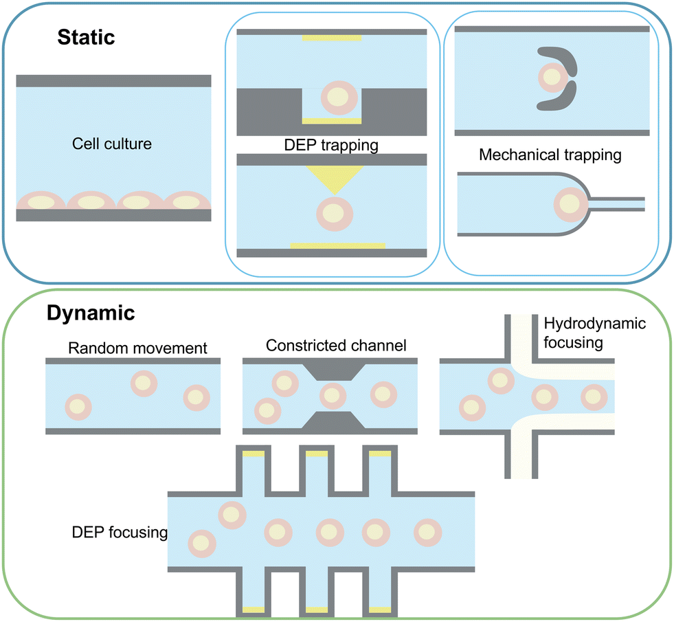 | ||
| Fig. 5 Key sample handling techniques in cell characterisation using IDS. | ||
While some studies forego trapping techniques,47 signal patterns are notably affected by cell positioning, as well as size and intrinsic properties, necessitating reduced cell flow rates for accurate and selective measurements. This is specifically true for broadband measurements where most of the setups use various trapping techniques to enhance SNR. However, these methods are low-throughput, and specific positioning of cells within traps can affect signals, particularly when multiple cells are trapped.108
Cell-substrate sensors, feature surface-modified electrode arrays positioned on the channel bottom, facilitating cell adhesion.129 Surface modification can be achieved through incubation of sterilised electrodes with cell culture media,130 surface activation by a protein promoting cell attachment such as fibronectin118 and laminin,131 or electrode passivation by adding an insulating layer to avoid contamination and sterilisation.119 These devices enable accurate analysis of cell behaviour changes in real-time as cells proliferate, migrate, spread, or detach from the electrode surface.132 In such setups, cells shield the electrodes from certain ions in the media,5 thereby reducing electrode polarisation. This allows for the investigation of cell properties at low frequencies. These setups are valuable for applications such as drug development,133 cancer modelling,134 cell differentiation,135 2D136 and 3D cell culture.3 However, they can be considered unsuitable for measurements at the scale of single cells and require additional cleaning, maintenance, and electrode surface modifications.
In dynamic approaches, cells flow through the electric field concentrated in the sensing zone, allowing high-throughput analysis. Challenges include response dependence on cell position,90 which can be mitigated by focusing methods to centre particle stream to the most sensitive area of the sensing zone.80 Examples of these techniques are hydrodynamic methods namely, inertial focusing and viscoelastic focusing,20 DEP focusing, and constricted channels.77 Integration of these approaches for cell focusing can be considered essential in developing sample-in-answer-out platforms137 integrated with IDS as demonstrated in ref. 138 where multichannel IDS is integrated with deterministic lateral displacement separation for separation and analysis of heterogeneous samples with wide size distributions. Passive manipulation methods (hydrodynamic focusing and constricted channels) are relatively simple to integrate and have been employed by many studies to enable high throughput IDS by performing pre-positioning of cells relative to electrodes. These techniques have been applied primarily in low frequency studies where 3D hydrodynamic focusing of cells results in increased SNR and enables accurate characterisation of different tumour cells.139 Additionally, the addition of constricted channels not only improves cell focusing, but also provides an opportunity to analyse mechano-electrical properties of the cell,140 enhancing cell classification and improving the detection success of single-cell IDS. However, this can result in challenges such as channel clogging, depending on the heterogeneity of the input sample. Alternatively, hydrodynamic pinching of cells has emerged as a suitable solution, where the introduction of a sheath flow can both focus cells141 and induce deformation, which can be used in a similar manner to a constricted channel, enabling applications such as single-cell mechanical characterisation.88
Fluid control traditionally relies on external pressure sources, e.g. syringe pumps, balancing controllability and repeatability against device portability. Current explorations aim to relocate liquid control systems onto platforms, recently reviewed by ref. 78. Novel techniques involve particle flow via applied static electric fields mimicking DEP particle movement,142 eliminating the need for frequent tubing changes, reducing contamination risks and enhancing device portability. However, these methods demand complex fabrication and face challenges in maintaining sample temperature uniformity and consistent repeatability. Moreover, maintaining sample temperature uniformity143 is particularly challenging. Temperature variations, particularly notable at higher frequencies where microwave energy absorption elevates sample temperature, must also be controlled to mitigate temperature-induced effects on responses.107
Medium conductivity can impact sensor sensitivity, electrode polarisation, and electrolysis. While cells are usually suspended in conductive culture media based on a combination of salts, less conductive liquids such as sucrose can maintain cell viability while reducing these side effects.46 However, this can impact cell size and shape over time.144 Integration of electrodes with cell purification microfluidics, notably spiral inertial microfluidics37 and magnetically activated cell sorting,145 allows for the concurrent detection and separation of particles and cells, including circulating tumour cells.146 Approaches aiming to induce volume variations among different cells before detection, such as mixing zones in hypertonic solutions, have significantly improved device sensitivity, particularly in live/dead assays.147
5 Measurement and data extraction techniques
There are several necessary steps to provide data from a sample, namely calibration, signal enhancement, and data analysis. Calibration ensures precision and removes non-sample influences. Signal sensitivity improvement involves employing techniques such as resonance-based methods for high-resolution analysis. Data analysis entails using models such as ECMs to gain insight into cell properties. Each of these aspects is reviewed in this section.5.1 Calibration techniques
Calibration usually involves two steps: 1) establishing reference planes at probe tips and 2) moving the reference planes closer to the MUT by removing the effect of parasitics unassociated with MUT properties, a process known as de-embedding. The first step can be achieved by measuring electrically well-defined standards, including loads, transmission lines (TLs) with various lengths, and resistors. While shorts and opens can be formed by discontinuities in the TLs or a short TL (thru), the load can sometimes be challenging to define. This standard made from an alloy with predefined electrical properties is usually deposited on the wafer, in between ground and trace electrodes. Various on-wafer calibration setups are available, which make use of different compositions of these standards. The choice of method depends on the operational frequency range, with different techniques showing varying error susceptibility.143As shown in Fig. 6, calibration standards can be defined on the chip and through steps of placing the probes on the standards, measuring S parameters, and moving on to the next standard, it's possible to calibrate the VNA to probe tips. The short open load thru (SOLT) method requires these four standards to accomplish calibration in the frequency range of DC to ≈15 GHz. Defining frequency-dependent standards can improve the accuracy of this technique at high frequencies.148 Line reflect match (LRM) is based on three standards: a TL as the line, either a short or an open as the reflect, and a load. This method covers a larger frequency range and offers a more compact setup, better suited for automated solutions without the need for operator interference to move the wafer multiple times.149 The thru reflect line (TRL) method, which offers better accuracy at higher frequencies, is based on three standards: a short TL as the thru, a reflect (open or short), and a line longer than a quarter wavelength (λ) at the centre frequency of calibration.150 This method is valid for frequencies where the line length is 20 to 160 degrees longer than the thru line, making this method inapplicable to low frequencies. Based on this, different line lengths should be used for accurate calibration across various frequency ranges. Multiline-TRL (m-TRL) has shown higher precision but requires substantial space, and the wafer probe has to be placed on a high number of lines, increasing the possibility of introducing errors.151 However, while other calibration standards (e.g., SOLT, LRM) are commercially available on substrates other than the MUT, TRL and m-TRL can be realized on the same substrate, reducing the errors due to dimension differences.
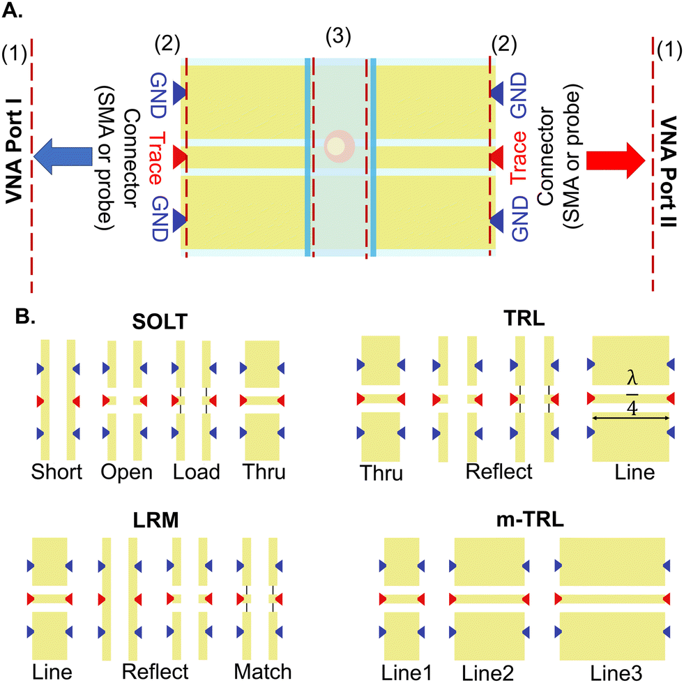 | ||
| Fig. 6 Overview of the calibration technique. A) Two steps of calibration to move reference planes (shown with dashed red lines) from VNA ports (1) to connector tips (2) followed by a de-embedding step to move them further to the sample (3). B) Calibration standards on-chip. Arrows represent the placement of on wafer probes. | ||
An alternative technique, single connection calibration, avoids the process of connecting and disconnecting the probes to multiple standards by introducing variations in impedance across the lines using multiple known samples, yielding good agreement with conventional techniques such as m-TRL while minimizing errors over a wide frequency range.152 Resources such as the European Metrology Programme for Innovation and Research (EMPIR)153 and tools such as StatistiCAL and Matlab Toolboxes such as RF Toolbox streamline the calibration process.154,155
5.2 Data analysis techniques
The methods utilised for interpreting data obtained from IDS have been reviewed previously for low-frequency measurements.20 These techniques mainly differ based on their data analysis. Data extracted from IDS can be analysed directly, focusing on size dependent properties of samples without considering the influence of the measuring techniques or sample conditions. Conversely, data analysis using models involves a de-embedding process to extract an intrinsic and frequency dependent cell property representing the polarisation of the cell and its components in an electromagnetic field. This procedure diminishes non-biological influences through numerical computations, ECMs, finite element models (FEMs), or their combination, albeit at the cost of increased post-processing overhead. Each of these techniques is suited for specific applications, explored further in subsequent sections.Comparing impedance variations introduced by different cells may not sufficiently distinguish between them, thereby prompting post-processing techniques to define size-independent parameters such as opacity. Opacity, derived from impedance ratios at high and low frequencies,157 signifies the electrical transparency of a cell. While valuable for membrane property analysis, at low frequencies (below the relaxation frequency of membrane polarization, about 1 MHz), it primarily reflects cell volume rather than providing effective discrimination.127 However, at higher frequencies, cytoplasm conductivity becomes a distinguishing factor. For instance, the ratio of impedance at 19 MHz to 0.5 MHz was found to correlate with acrosome integrity in a fertility study.158 Additionally, in GHz measurements, opacity was shown to aid in differentiating cells with similar phenotypes with remarkable sensitivity.79
Another metric, phase contrast (ϕZ), derived from the variation of impedance phase at high and low frequencies, has shown to be reflective of differences in cell interior conductivity and permittivity. This parameter has shown promise in describing cell electrophysiology and correlating with cell tumorigenicity in certain cancer types.12 Moreover, a new metric, the ‘tilt-index’, has been used to extract the exact relaxation frequency of cell membranes from measurements at single or multiple low frequencies. This index quantifies the tilt level of the impedance pulse when a micro-object passes through the electric field.33 It has been demonstrated that the tilt level of the impedance signal is affected by intracellular distribution, and increased frequency can elevate the distribution of tilt levels, highlighting the frequency at which the cell membrane becomes conductive.1 This index can shift the analysis focus from outer cell properties, such as cell size and membrane electrical properties, to inner characteristics, such as cytoplasm conductivity and organelle properties,46 without the need for broadband frequency analysis.
After establishing the sensor ECM, fluidic channel electrical characteristics can be extracted by several techniques. Calibration-free methods are based on the eigenvalue technique where identical TLs with varying lengths (line-line technique) or a single TL covered by different samples (single-line technique) are used to determine the unknown sample's γ.122 The general line-line approach accommodates material and length variations, proving more suitable for higher frequencies.159 Relative measurements can be done using a zero-length channel where a section of the TL is covered by a slab of PDMS resembling microfluidic channel walls without the sample.109 Another technique is to use fitting and optimisation methods, such as least squares125 or equivalent circuit fitting algorithms160 to fit a model to the collected data from a TL covered by the sample. The collected data can be converted into RLCG by calculating γ from recorded S-parameters (after converting them to the transmission matrix).125 The model calculates the S parameters from an initial guess on RLCG. This initial guess can be based on the sample's permittivity and the RLCG of the TLs, using developed models and calibration lines to measure the properties of the lines covered by air or channel walls.
While these techniques are based on calculations of γ, the reference device technique compares fluid-filled, polystyrene-beads (control particles) suspended in the media, and empty devices to deduce fluid properties without the intricate ECM.109 This method is better suited to higher frequencies where the contrast between the S-parameters of air and fluid-filled devices is most accurate.125 Loading the sensing zone with known fluids is another approach,161 enabling permittivity calculation using formulations such as the Havriliak–Negami relaxation.162 This technique depends on liquids with known permittivity which is influenced by factors such as temperature. An advancement in this area is based on measurements of reference liquids without presumptions about their permittivities,163 yet this also relies on relative measurements, lowering accuracy at lower frequencies.125 Using liquids compensates for electrode polarisation by using a reference material with similar conductivity for parameter calculation and subsequent subtraction from sample measurements.121
The final step in this process is to relate the measured electrical properties to the sample permittivity. Changes in sample permittivity can be attributed to alterations in either 1) capacitance and conductance or 2) effective permittivity within the sensing area. Techniques such as conformal mapping,142 FEM simulations (using software such as Comsol, HFSS, and Q3D),164 or direct measurement methods such as the series-resistor technique165 can establish the relationship between changes in sample relative permittivity and these factors. By calculating the sensing zone's γ or impedance, the sample's permittivity can be extracted. In resonators, this relationship influences the resonant frequency.
To analyse the electrical properties of cells within a sample, various modelling techniques are employed. Creating an ECM using lumped elements is a common method, considering components such as cell membranes, cytoplasm, and extracellular media. These models are depicted in Fig. 7. Models such as the Fricke–Morse circuit assess cell size and polarization, while Cole models examine morphological alterations in cell monolayers concerning α and β dispersions.18 Other models include additional elements to model the cell membrane and cytoplasm more accurately. The fringing field or edge effect, resulting from electric field non-uniformity in the channel, can be corrected by defining a geometrical factor determined by Schwartz–Christoffel mapping.166 Numerical methods summarised in Fig. 2, such as single-shell and double-shell models, provide alternatives for cell analysis, enabling investigation into nucleus size effects.8
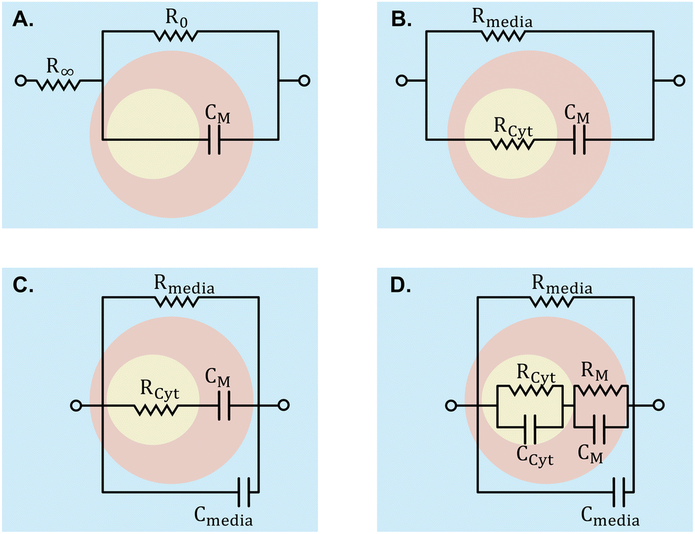 | ||
| Fig. 7 ECMs employed to interpret signals into cell properties. A) Cole model, wherein Rinf and R0 denote high and low-frequency resistance, respectively. B) Fricke model. C) and D) are extensions of the Fricke model integrating supplementary elements for increased precision. In these models, while R and C signify resistance and capacitance, the M subscript designates membrane properties, Cyt represents cytoplasm properties, and ‘media’ denotes properties of the surrounding medium. | ||
FEM simulation of the sensing zone aids in translating membrane capacitance and cytoplasm resistance to parameters specific to a cell type, thereby enhancing cell differentiation accuracy,66 although it requires larger computational resources. Comparative studies of these two methods are available.166 For adhesive cells, a statistical technique-based method has been proposed to account for the biological diversity of various cells.167 Finally, neural networks have been proposed for converting raw impedance signals to cell properties,44 but adequate training is crucial. Developing supervised or unsupervised learning approaches specifically designed for cell impedance spectroscopy has been shown to effectively detect and categorise unknown cells.44
Following data acquisition, either in the form of impedance or dielectric properties of the sample, it is necessary to reduce unwanted noises either using filters or by using techniques (covered in the next section) which improve the overall SNR. This step ensures that a clear signal is provided for algorithm training. Consequently, signal features such as time constants, the relationship between amplitude and phase, opacity, tilt index, etc. can be used as algorithm inputs. Additionally, normalization or standardization can ensure data comparability and also correct variations due to environmental or instrumental factors. While this process is usually handled manually, it has been demonstrated that the recurrent neural network can also handle raw signal quantification65 and classifying them based on signal metrics.168
Accordingly, models may either make use of supervised or unsupervised learning. In supervised learning, labels such as cell type,168 size and trajectory,65 deformability,98 state,169 or specific physiological condition170 are available and the extracted features can be correlated through trained models such as decision trees,70 random forests, support vector machines,171 or neural networks.172 To reduce the impacts of specific conditions in the training data resulting in overfitting the use of multiple convolutional neural networks44 and using a parallel setup to measure the training and target data simultaneously for data normalization170 have been examined.
On the other hand, algorithms such as k-means173 or Gaussian mixture models174 can group cells based on the similarities of their spectrum, without knowing the number of subpopulations. This yields phenotypes without predefined labels and is useful to identify cells in a heterogenous population.28 Further, Honrado et al.169 combined this technique with supervised training, by feeding the clustered data to a supervised learning method to quantify each subpopulation. Finally, deep learning models, such as convolutional neural networks (CNNs) or recurrent neural networks (RNNs), are especially useful for handling complex and non-linear relationships between spectral features and biological properties. These models have been used to trace cells at multiple channels simultaneously175 and classify coincident cells.44
The inhomogeneous electric field in the sensing zone in most setups, especially those based on coplanar and parallel electrodes, makes it necessary to account for the dependence of the recorded signal on the cell's vertical position as a significant source of noise. Fabrication techniques such as particle focusing units can help by aligning the cell on the mid-line. However, post-processing techniques can also be used to quantify and, therefore, compensate for cell position, mostly by assuming that the cell is a spherical particle, at the expense of complex post-processing steps.
Defining new parameters based on signal shape has shown to be effective in considering the effect of cell height. Examples include (1) altering electrode geometry – e.g., star-shaped electrodes179 or non-parallel electrodes,180,181 (2) analysing peak-to-peak time of current signals (oblique and transverse) and their ratio,182 (3) calculating amplitude relative difference and relative prominence using a combination of coplanar and liquid electrodes101 or by increasing the number of non-signal electrodes,182 or (4) modifying wiring configurations of parallel electrodes, such as applying voltage to diagonally opposite electrodes to extract cell electrical position.183 Similarly, digital filters such as the extended Kalman filter179 have shown to correct the signal based on particle position. Finally, the Bayesian approach184 and neural networks44 have shown to be able to decompose the effect of signals of multiple particles passing through the sensing zone into individual particle effects.
6 Conclusion and future outlook
Impedance and dielectric spectroscopy shows promise for cell identification and characterisation across fields such as diagnosis, medicine, biotechnology, food, and liquid analysis. This review offers a guide for implementing IDS for cell analysis and characterisation. Key steps involve selecting relevant frequency ranges, setting up the appropriate measurement configuration, employing calibration, and processing signals to extract information. This review accordingly offers a comprehensive reference of current technological advancements.Despite progress, several areas require further attention. Low-frequency analysis remains prevalent for applications such as cytometry, membrane analysis, and cell response to stimulation. However, electrode polarisation effects at these frequencies present challenges for sensitive measurement. Recent advancements using neural networks show promise in identifying cell viability or infection status. While high frequencies can be used to interrogate specific cell features, GHz resonators have limited bandwidths, restricting their ability to simultaneously detect large-scale features. Enhancing the resonator Q factor for characterising cells in media with similar properties is also essential. Conversely, broadband analysis holds theoretical promise for comprehensive insights into cell properties, but faces challenges in sensitivity, impedance matching, and throughput. Advancements in cell trapping and analysis speed could alleviate these limitations.
The future of on-chip broadband IDS promises versatility across a range of applications. Optimising electrode configurations, cell handling techniques, and integrating machine learning for real-time data analysis can further improve this technique. Machine learning algorithms enable prediction of cell condition as well as classification of cells in real-time. This technique enables simultaneous analysis of various parameters such as membrane resistance, cell electrical radius, etc., from a single dataset, accelerating research in drug screening and diagnostics with a high sensitivity. Exploring molecular–cellular interactions at microwave and millimetre-wave frequencies could also offer insights into their effects on cell behaviour.119 Further research may focus on signal sensitivity to cell properties and enhancing sensor sensitivity across high and low frequencies, potentially through tailored electrode configurations. Transition of these setups to point-of-care applications requires miniaturized wave form generators, reducing the need for expensive equipment and simplifying calibration processes for non-specialists. Recent advancements in VNA-on-chip, lock-in-amplifier-on-chip, and waveform generator-on-chip hold promise for research translation to clinical applications.
Data availability
This review does not include any primary research results, software, or code. No new data were generated or analysed as part of this work.Conflicts of interest
The authors have no conflicts of interest to declare. All co-authors have seen and agreed with the contents of the manuscript and there is no financial interest to report. We certify that the submission is original work and is not under review at any other publication.Acknowledgements
The authors would like to thank the Biotechnology and Biological Sciences Research Council (Grant ref DTP3 2020-2025 entry - BB/T008725/1) for their financial support.Notes and references
- T. Tang, X. Liu, Y. Yuan, T. Zhang, R. Kiya, Y. Yang, K. Suzuki, Y. Tanaka, M. Li and Y. Hosokawa, et al. , Microsyst. Nanoeng., 2022, 8, 68 Search PubMed.
- J. Kafka, O. Pänke, B. Abendroth and F. Lisdat, Electrochim. Acta, 2008, 53, 7467–7474 Search PubMed.
- C. Hildebrandt, H. Büth, S. Cho and H. Thielecke, et al. , J. Biotechnol., 2010, 148, 83–90 Search PubMed.
- S. E. De León, A. Pupovac and S. L. McArthur, Biotechnol. Bioeng., 2020, 117, 1230–1240 Search PubMed.
- X. Bao, I. Ocket, J. Bao, J. Doijen, J. Zheng, D. Kil, Z. Liu, B. Puers, D. Schreurs and B. Nauwelaers, IEEE Trans. Microwave Theory Tech., 2018, 66, 5750–5759 Search PubMed.
- E. U. Akabuogu, L. Zhang, R. Krasovec, I. S. Roberts and T. A. Waigh, Nano Lett., 2024, 24, 2234–2241 Search PubMed.
- Y. Feng, L. Huang, P. Zhao, F. Liang and W. Wang, Anal. Chem., 2019, 91, 15204–15212 Search PubMed.
- X. Du, C. Ladegard, X. Ma, X. Cheng and J. C. Hwang, IEEE MTT-S International Microwave Biomedical Conference, 2020, pp. 1–4 Search PubMed.
- M. Mertens, M. Chavoshi, O. Peytral-Rieu, K. Grenier and D. Schreurs, IEEE Microw. Mag., 2023, 24, 49–62 Search PubMed.
- L. Huang, F. Liang, Y. Feng, P. Zhao and W. Wang, Microsyst. Nanoeng., 2020, 6, 57 Search PubMed.
- C. D. M. Campos, K. T. Uning, P. Barmuta, T. Markovic, R. Yadav, G. Mangraviti, I. Ocket, W. Van Roy, L. Lagae and C. Liu, Biomed. Microdevices, 2023, 25, 39 Search PubMed.
- J. McGrath, C. Honrado, J. Moore, S. Adair, W. Varhue, A. Salahi, V. Farmehini, B. Goudreau, S. Nagdas and E. Blais, et al. , Anal. Chim. Acta, 2020, 1101, 90–98 Search PubMed.
- A. Mansoorifar, A. Koklu, S. Ma, G. V. Raj and A. Beskok, Anal. Chem., 2018, 90, 4320–4327 Search PubMed.
- A. Zhbanov and S. Yang, Anal. Methods, 2017, 9, 3302–3313 Search PubMed.
- S. M. Moqadam, P. K. Grewal, Z. Haeri, P. A. Ingledew, K. Kohli and F. Golnaraghi, J. Electr. Bioimpedance, 2018, 9, 17 Search PubMed.
- C. V. Bertelsen, G. E. Skands, M. González Díaz, M. Dimaki and W. E. Svendsen, ACS Omega, 2023, 8, 7714–7721 Search PubMed.
- C. V. Bertelsen, J. C. Franco, G. E. Skands, M. Dimaki and W. E. Svendsen, Sensors, 2020, 20, 6339 Search PubMed.
- S. Abasi, J. R. Aggas, G. G. Garayar-Leyva, B. K. Walther and A. Guiseppi-Elie, ACS Meas. Sci. Au, 2022, 2, 495–516 Search PubMed.
- I. Showkat, F. A. Khanday and M. R. Beigh, Med. Biol. Eng. Comput., 2023, 61, 927–950 Search PubMed.
- C. Honrado, P. Bisegna, N. S. Swami and F. Caselli, Lab Chip, 2021, 21, 22–54 Search PubMed.
- Y. Xu, X. Xie, Y. Duan, L. Wang, Z. Cheng and J. Cheng, Biosens. Bioelectron., 2016, 77, 824–836 Search PubMed.
- Y.-S. Chen, C.-H. Huang, P.-C. Pai, J. Seo and K. F. Lei, Biosensors, 2023, 13, 83 Search PubMed.
- H. T. Nguyen, H. A. Nguyen, D. H. Tran, H. Cao, C. D. Trinh, T. T. Bui and Q. L. Do, et al. , Analyst, 2023, 148(9), 1912–1929 Search PubMed.
- S. Zhu, X. Zhang, Z. Zhou, Y. Han, N. Xiang and Z. Ni, Talanta, 2021, 233, 122571 Search PubMed.
- H. Daguerre, M. Solsona, J. Cottet, M. Gauthier, P. Renaud and A. Bolopion, Lab Chip, 2020, 20, 3665–3689 Search PubMed.
- M. S. Hanay, in Handbook of Single-Cell Technologies, Springer, 2021, pp. 973–996 Search PubMed.
- T. Julian, T. Tang, Y. Hosokawa and Y. Yalikun, Biomicrofluidics, 2023, 17(5), 051506 Search PubMed.
- T. Tang, T. Julian, D. Ma, Y. Yang, M. Li, Y. Hosokawa and Y. Yalikun, Anal. Chim. Acta, 2023, 1269, 341424 Search PubMed.
- C. Ferguson, Y. Zhang, C. Palego and X. Cheng, Sensors, 2023, 23, 5990 Search PubMed.
- V. Raicu and Y. Feldman, Dielectric relaxation in biological systems: Physical principles, methods, and applications, Academic, 2015 Search PubMed.
- K. Asami, J. Non-Cryst. Solids, 2002, 305, 268–277 Search PubMed.
- F. Gökçe, P. S. Ravaynia, M. M. Modena and A. Hierlemann, Biomicrofluidics, 2021, 15, 061302 Search PubMed.
- T. Tang, X. Liu, R. Kiya, Y. Shen, Y. Yuan, T. Zhang, K. Suzuki, Y. Tanaka, M. Li and Y. Hosokawa, et al. , Biosens. Bioelectron., 2021, 193, 113521 Search PubMed.
- A. De Ninno, R. Reale, A. Giovinazzo, F. R. Bertani, L. Businaro, P. Bisegna, C. Matteucci and F. Caselli, Biosens. Bioelectron., 2020, 150, 111887 Search PubMed.
- D. Spencer, V. Hollis and H. Morgan, Biomicrofluidics, 2014, 8, 064124 Search PubMed.
- C. Petchakup, H. M. Tay, W. H. Yeap, R. Dalan, S. C. Wong, K. H. H. Li and H. W. Hou, Biosens. Bioelectron., 2018, 118, 195–203 Search PubMed.
- C. Petchakup, H. M. Tay, K. H. H. Li and H. W. Hou, Lab Chip, 2019, 19, 1736–1746 Search PubMed.
- C. Petchakup, P. E. Hutchinson, H. M. Tay, S. Y. Leong, K. H. H. Li and H. W. Hou, Sens. Actuators, B, 2021, 339, 129864 Search PubMed.
- J. Zhu, S. Pan, H. Chai, P. Zhao, Y. Feng, Z. Cheng, S. Zhang and W. Wang, Small, 2024, 2310700 Search PubMed.
- M. Shaker, L. Colella, F. Caselli, P. Bisegna and P. Renaud, Lab Chip, 2014, 14, 2548–2555 Search PubMed.
- A. Salahi, C. Honrado, A. Rane, F. Caselli and N. S. Swami, Anal. Chem., 2022, 94, 2865–2872 Search PubMed.
- A. Rane, J. Jarmoshti, A.-B. Siddique, S. Adair, K. Torres-Castro, C. Honrado, T. W. Bauer and N. S. Swami, Lab Chip, 2024, 24, 561–571 Search PubMed.
- T. Chen, D. Dubuc, M. Poupot, J.-J. Fournie and K. Grenier, IEEE Trans. Microwave Theory Tech., 2012, 60, 4171–4177 Search PubMed.
- F. Caselli, R. Reale, A. De Ninno, D. Spencer, H. Morgan and P. Bisegna, Lab Chip, 2022, 22, 1714–1722 Search PubMed.
- G. Schade-Kampmann, A. Huwiler, M. Hebeisen, T. Hessler and M. Di Berardino, Cell Proliferation, 2008, 41, 830–840 Search PubMed.
- X. Ma, X. Du, L. Li, H. Li, X. Cheng and J. C. Hwang, IEEE J. Electromagn. RF Microw. Med. Biol., 2019, 4, 37–44 Search PubMed.
- H. Li, C. Multari, C. Palego, X. Ma, X. Du, Y. Ning, J. Buceta, J. C. Hwang and X. Cheng, Sens. Actuators, B, 2018, 255, 1614–1622 Search PubMed.
- Y. Zhou, S. Basu, E. Laue and A. A. Seshia, Biosens. Bioelectron., 2016, 81, 249–258 Search PubMed.
- P. Ghassemi, K. S. Harris, X. Ren, B. M. Foster, C. D. Langefeld, B. A. Kerr and M. Agah, Sens. Actuators, B, 2020, 321, 128522 Search PubMed.
- Y. Zhao, D. Chen, Y. Luo, H. Li, B. Deng, S.-B. Huang, T.-K. Chiu, M.-H. Wu, R. Long and H. Hu, et al. , Lab Chip, 2013, 13, 2272–2277 Search PubMed.
- R. Reale, A. De Ninno, T. Nepi, P. Bisegna and F. Caselli, IEEE Trans. Biomed. Eng., 2022, 70(2), 565–572 Search PubMed.
- K. Wang, Y. Liu, D. Chen, J. Wang and J. Chen, IEEE Trans. Electron Devices, 2022, 69, 2015–2022 Search PubMed.
- X. Ren, P. Ghassemi, J. S. Strobl and M. Agah, Biomicrofluidics, 2019, 13(4), 044103 Search PubMed.
- M. Jiang, X. Wang, X. Zhao, Y. Teng, J. Chen, J. Wang and W. Yue, Cytometry, Part A, 2021, 99, 1114–1122 Search PubMed.
- M. Wang, J. Zhang, H. Tan, D. Chen, Y. Lei, Y. Li, J. Wang and J. Chen, Cytometry, Part A, 2022, 101, 639–647 Search PubMed.
- X. Zou, D. C. Spencer, J. Chen and H. Morgan, RSC Adv., 2024, 14, 34270–34278 Search PubMed.
- A. Tamra, A. Zedek, M.-P. Rols, D. Dubuc and K. Grenier, IEEE Trans. Biomed. Eng., 2022, 69, 3407–3414 Search PubMed.
- A. Tamra, D. Dubuc, M.-P. Rols and K. Grenier, IEEE Trans. Microwave Theory Tech., 2017, 65, 3512–3518 Search PubMed.
- Y. Ye, X. Luan, L. Zhang, W. Zhao, J. Cheng, M. Li, Y. Zhao and C. Huang, Micromachines, 2020, 11, 856 Search PubMed.
- D. C. Spencer, T. F. Paton, K. T. Mulroney, T. J. Inglis, J. M. Sutton and H. Morgan, Nat. Commun., 2020, 11, 5328 Search PubMed.
- J. H. Moore, A. Salahi, C. Honrado, C. Warburton, S. Tate, C. A. Warren and N. S. Swami, ACS Infect. Dis., 2023, 9, 1878–1888 Search PubMed.
- C. Honrado, L. Ciuffreda, D. Spencer, L. Ranford-Cartwright and H. Morgan, J. R. Soc., Interface, 2018, 15, 20180416 Search PubMed.
- G. Poiroux, D. Dubuc, M. Hosseini, F. Artis, A. Tamra, M. Tosolini, F. Pont, C. Bosc, E. Saland and F. Lopez, et al. , Int. J. Biotechnol. Bioeng., 2020, 6(5), 1–14 Search PubMed.
- C. A. Ferguson, J. C. Hwang, Y. Zhang and X. Cheng, Sensors, 2023, 23, 1001 Search PubMed.
- C. Honrado, J. S. McGrath, R. Reale, P. Bisegna, N. S. Swami and F. Caselli, Anal. Bioanal. Chem., 2020, 412, 3835–3845 Search PubMed.
- Y. Zhao, K. Wang, D. Chen, B. Fan, Y. Xu, Y. Ye, J. Wang, J. Chen and C. Huang, Biosens. Bioelectron., 2018, 111, 138–143 Search PubMed.
- J. Jarmoshti, A.-B. Siddique, A. Rane, S. Mirhosseini, S. J. Adair, T. W. Bauer, F. Caselli and N. S. Swami, Small, 2024, 2407212 Search PubMed.
- M. Wang, H. Tan, Y. Li, X. Chen, D. Chen, J. Wang and J. Chen, Cytometry, Part A, 2023, 103, 439–446 Search PubMed.
- J. A. Osterberg, N. Dahal, R. Divan, C. S. Miller, D. Moline, T. P. Caldwell, X. Yu, S. W. Harcum and P. Wang, IEEE Trans. Microwave Theory Tech., 2021, 69, 1875–1886 Search PubMed.
- N. Dahal, C. Peak, C. Ehrett, J. Osterberg, M. Cao, R. Divan and P. Wang, Sensors, 2024, 24, 2870 Search PubMed.
- N. Haandbæk, S. C. Bürgel, F. Rudolf, F. Heer and A. Hierlemann, ACS Sens., 2016, 1, 1020–1027 Search PubMed.
- Y. Park, H. W. Kim, J. Yun, S. Seo, C.-J. Park, J. Z. Lee and J.-H. Lee, BioMed Res. Int., 2016, 2016(1), 8748023 Search PubMed.
- U. F. Pliquett and K. H. Schoenbach, IEEE Trans. Dielectr. Electr. Insul., 2009, 16, 1273–1279 Search PubMed.
- V. Viswam, R. Bounik, A. Shadmani, J. Dragas, C. Urwyler, J. A. Boos, M. E. J. Obien, J. Mueller, Y. Chen and A. Hierlemann, IEEE Trans. Biomed. Circuits Syst., 2018, 12, 1356–1368 Search PubMed.
- A. Rumiantsev and R. Doerner, IEEE Microw. Mag., 2013, 14, 46–58 Search PubMed.
- D. Müller, J. Schäfer, D. Geenen, H. Massler, A. Tessmann, A. Leuther, T. Zwick and I. Kallfass, 2017 47th European Microwave Conference, 2017, pp. 900–903 Search PubMed.
- Y. Fu, Q. Yuan and J. Guo, Microfluid. Nanofluid., 2017, 21, 1–4 Search PubMed.
- F. Perdigones Sánchez, Micromachines, 2021, 12(2), 175 Search PubMed.
- J.-C. Chien, A. Ameri, E.-C. Yeh, A. N. Killilea, M. Anwar and A. M. Niknejad, Lab Chip, 2018, 18, 2065–2076 Search PubMed.
- Z. Zhang, X. Huang, K. Liu, T. Lan, Z. Wang and Z. Zhu, Biosensors, 2021, 11, 470 Search PubMed.
- J.-C. Chien, M. Anwar, E.-C. Yeh, L. P. Lee and A. M. Niknejad, IEEE MTT-S International Microwave Symposium, 2014, pp. 1–4 Search PubMed.
- J.-C. Chien and A. M. Niknejad, IEEE J. Solid-State Circuits, 2015, 51, 457–472 Search PubMed.
- C. Watts, S. M. Hanham, J. P. Armstrong, M. M. Ahmad, M. M. Stevens and N. Klein, IEEE J. Electromagn. RF Microw. Med. Biol., 2019, 4, 97–108 Search PubMed.
- S. Mohammadi, R. Narang, M. Mohammadi Ashani, H. Sadabadi, A. Sanati-Nezhad and M. H. Zarifi, Microw. Opt. Technol. Lett., 2019, 61, 2534–2539 Search PubMed.
- D. Dubuc, O. Mazouffre, C. Llorens, T. Taris, M. Poupot, J.-J. Fournié, J.-B. Begueret and K. Grenier, Analog Integr. Circuits Signal Process., 2013, 77, 135–142 Search PubMed.
- S. Gawad, L. Schild and P. Renaud, Lab Chip, 2001, 1, 76–82 Search PubMed.
- F. Asphahani and M. Zhang, Analyst, 2007, 132, 835–841 Search PubMed.
- C. Petchakup, H. Yang, L. Gong, L. He, H. M. Tay, R. Dalan, A. J. Chung, K. H. H. Li and H. W. Hou, Small, 2022, 18, 2104822 Search PubMed.
- A. De Ninno, V. Errico, F. R. Bertani, L. Businaro, P. Bisegna and F. Caselli, Lab Chip, 2017, 17, 1158–1166 Search PubMed.
- D. Spencer and H. Morgan, ACS Sens., 2020, 5, 423–430 Search PubMed.
- T. Sun, D. Holmes, S. Gawad, N. G. Green and H. Morgan, Lab Chip, 2007, 7, 1034–1040 Search PubMed.
- N. Haandbæk, S. C. Bürgel, F. Heer and A. Hierlemann, et al. , Lab Chip, 2014, 14, 3313–3324 Search PubMed.
- M. A. Mansor, M. Takeuchi, M. Nakajima, Y. Hasegawa and M. R. Ahmad, Appl. Sci., 2017, 7, 170 Search PubMed.
- E. Rollo, E. Tenaglia, R. Genolet, E. Bianchi, A. Harari, G. Coukos and C. Guiducci, Biosens. Bioelectron., 2017, 94, 193–199 Search PubMed.
- X. Xing and L. Yobas, IEEE 29th International Conference on Micro Electro Mechanical Systems, 2016, pp. 749–752 Search PubMed.
- X. Yuan, T. Li, F. Yu, C. Han and X. Xing, 2022 IEEE 35th International Conference on Micro Electro Mechanical Systems Conference (MEMS), 2022, pp. 880–883 Search PubMed.
- L. Huang, P. Zhao and W. Wang, Lab Chip, 2018, 18, 2359–2368 Search PubMed.
- D. Yang, Y. Zhou, Y. Zhou, J. Han and Y. Ai, Biosens. Bioelectron., 2019, 133, 16–23 Search PubMed.
- G. Mernier, E. Duqi and P. Renaud, Lab Chip, 2012, 12, 4344–4349 Search PubMed.
- T.-K. Chiu, Y. Zhao, D. Chen, C.-H. Hsieh, K. Wang, W.-P. Chou, C.-J. Liao, H.-Y. Wang, B. Fan and J. Wang, et al. , Sens. Actuators, B, 2017, 246, 29–37 Search PubMed.
- R. Reale, A. De Ninno, L. Businaro, P. Bisegna and F. Caselli, Lab Chip, 2019, 19, 1818–1827 Search PubMed.
- A. Salim, S.-H. Kim, J. Y. Park and S. Lim, J. Sens., 2018, 2018, 1–13 Search PubMed.
- N. Meyne, G. Fuge, A.-P. Zeng and A. F. Jacob, IEEE J. Electromagn. RF Microw. Med. Biol., 2017, 1, 98–104 Search PubMed.
- C.-F. Liu, M.-H. Wang and L.-S. Jang, Sens. Actuators, B, 2018, 263, 129–136 Search PubMed.
- T. Reinecke, J.-G. Walter, T. Kobelt, A. Ahrens, T. Scheper and S. Zimmermann, J. Sens. Sens. Syst., 2018, 7, 101–111 Search PubMed.
- R. N. Simons, Coplanar waveguide circuits, components, and systems, John Wiley & Sons, 2004 Search PubMed.
- K. Grenier, D. Dubuc, T. Chen, F. Artis, T. Chretiennot, M. Poupot and J.-J. Fournie, IEEE Trans. Microwave Theory Tech., 2013, 61, 2023–2030 Search PubMed.
- T. Chen, F. Artis, D. Dubuc, J. Fournie, M. Poupot and K. Grenier, IEEE MTT-S International Microwave Symposium Digest, 2013, pp. 1–4 Search PubMed.
- N. Meyne, S. Latus and A. F. Jacob, GeMiC 2014; German Microwave Conference, 2014, pp. 1–4 Search PubMed.
- S. Stuchly and C. Bassey, Meas. Sci. Technol., 1998, 9, 1324 Search PubMed.
- X. Bao, I. Ocket, J. Zheng, J. Bao, M. Zhang, D. Kil, V. Franssens, B. Puers, D. M.-P. Schreurs and B. K. Nauwelaers, IEEE/MTT-S International Microwave Symposium, 2018, pp. 903–906 Search PubMed.
- H. Chai, Y. Feng, J. Zhu, X. Meng, F. Liang, J. Bai and W. Wang, ACS Sens., 2023, 8, 2681–2690 Search PubMed.
- S. Yan and D. Yuan, Talanta, 2021, 221, 121401 Search PubMed.
- D. Spencer and H. Morgan, Lab Chip, 2011, 11, 1234–1239 Search PubMed.
- A. Amanati Shahri, A. H. Omidvar, G. Pamplona Rehder and A. L. C. Serrano, Sensors, 2022, 22, 3265 Search PubMed.
- S. Middya, G. S. K. Schierle, G. G. Malliaras and V. F. Curto, in Chemical Solution Synthesis for Materials Design and Thin Film Device Applications, Elsevier, 2021, pp. 277–307 Search PubMed.
- W. Chen, D. Dubuc and K. Grenier, IEEE Topical Conference on Biomedical Wireless Technologies, Networks, and Sensing Systems, 2016, pp. 81–83 Search PubMed.
- A. Bouafsoun, A. Othmane, N. Jaffrézic-Renault, A. Kerkeni, O. Thoumire, A. Prigent and L. Ponsonnet, Mater. Sci. Eng., C, 2008, 28, 653–661 Search PubMed.
- Y. Lu and Y. Shi, Bioelectrochemistry, 2023, 154, 108554 Search PubMed.
- Y. Feldman, I. Ermolina and Y. Hayashi, IEEE Trans. Dielectr. Electr. Insul., 2003, 10, 728–753 Search PubMed.
- H. Schwan, Ann. N. Y. Acad. Sci., 1968, 148, 191–209 Search PubMed.
- K. Grenier, D. Dubuc, P.-E. Poleni, M. Kumemura, H. Toshiyoshi, T. Fujii and H. Fujita, IEEE Trans. Microwave Theory Tech., 2009, 57, 3246–3253 Search PubMed.
- A. Ayoib, U. Hashim, M. M. Arshad and V. Thivina, IEEE EMBS Conference on Biomedical Engineering and Sciences, 2016, pp. 226–229 Search PubMed.
- S. Pinon, D. L. Diedhiou, A. Boukabache, V. Conédéra, D. Bourrier, A. M. Gué, G. Prigent, E. Rius, C. Quendo and B. Potelonet al., IEEE/MTT-S International Microwave Symposium Digest, 2012, pp. 1–3 Search PubMed.
- S. Liu, N. D. Orloff, C. A. Little, W. Zhao, J. C. Booth, D. F. Williams, I. Ocket, D. M.-P. Schreurs and B. Nauwelaers, IEEE Trans. Microwave Theory Tech., 2017, 65, 5063–5073 Search PubMed.
- A. H. Allah, G. A. Eyebe and F. Domingue, IEEE Sens. J., 2022, 22, 10541–10550 Search PubMed.
- K. Cheung, S. Gawad and P. Renaud, Cytometry, Part A, 2005, 65, 124–132 Search PubMed.
- J. Q. Cui, Y. Tian, Z. Wu, L. Zhang, W. C. Cho, S. Yao and Y. Lin, Nano Lett., 2024, 24(45), 14522–14530 Search PubMed.
- C. Xiao and J. H. Luong, Biotechnol. Prog., 2003, 19, 1000–1005 Search PubMed.
- Z. Zhang, X. Yuan, H. Guo and P. Shang, Biosensors, 2023, 13, 322 Search PubMed.
- Y. Qiu, R. Liao and X. Zhang, Anal. Chem., 2008, 80, 990–996 Search PubMed.
- T. A. Nguyen, T.-I. Yin, D. Reyes and G. A. Urban, Anal. Chem., 2013, 85, 11068–11076 Search PubMed.
- Y. Pan, N. Hu, X. Wei, L. Gong, B. Zhang, H. Wan and P. Wang, Biosens. Bioelectron., 2019, 130, 344–351 Search PubMed.
- J. Hong, K. Kandasamy, M. Marimuthu, C. S. Choi and S. Kim, Analyst, 2011, 136, 237–245 Search PubMed.
- A. Elghajiji, X. Wang, S. D. Weston, G. Zeck, B. Hengerer, D. Tosh and P. R. Rocha, Adv. Biol., 2021, 5, 2100330 Search PubMed.
- L. D'Alvia, S. Carraro, B. Peruzzi, E. Urciuoli, L. Palla, Z. Del Prete and E. Rizzuto, Sensors, 2022, 22, 4383 Search PubMed.
- G. Adedokun, M. Alipanah and Z. H. Fan, Lab Chip, 2024, 24, 3626–3650 Search PubMed.
- K. Torres-Castro, J. Jarmoshti, L. Xiao, A. Rane, A. Salahi, L. Jin, X. Li, F. Caselli, C. Honrado and N. S. Swami, Adv. Mater. Technol., 2023, 8, 2201463 Search PubMed.
- C. Ni, M. Yang, S. Yang, Z. Zhu, Y. Chen, L. Jiang and N. Xiang, Lab Chip, 2024, 24, 4333–4343 Search PubMed.
- Y. Feng, J. Zhu, H. Chai, W. He, L. Huang and W. Wang, Small, 2023, 19, 2303416 Search PubMed.
- J. Zhu, Y. Feng, H. Chai, F. Liang, Z. Cheng and W. Wang, Lab Chip, 2023, 23, 2531–2539 Search PubMed.
- Y. Yang, Y. He, H. Zhang, K. Huang, G. Yu and P. Wang, IEEE Topical Conference on Biomedical Wireless Technologies, Networks, and Sensing Systems, 2013, pp. 28–30 Search PubMed.
- J. C. Booth, J. Mateu, M. Janezic, J. Baker-Jarvis and J. A. Beall, IEEE MTT-S International Microwave Symposium Digest, 2006, pp. 1750–1753 Search PubMed.
- S. V. Rudenko, Blood Cells, Mol., Dis., 2009, 42, 252–261 Search PubMed.
- Z. Lin, S.-Y. Lin, P. Xie, C.-Y. Lin, G. M. Rather, J. R. Bertino and M. Javanmard, Sci. Rep., 2020, 10, 3015 Search PubMed.
- S.-I. Han and K.-H. Han, Anal. Chem., 2015, 87, 10585–10592 Search PubMed.
- Q. Zi, W. Ding, C. Sun, S. Li, D. Gao, L. He, J. Liu, L. Xu and B. Qiu, Biosens. Bioelectron., 2020, 148, 111820 Search PubMed.
- S. Padmanabhan, P. Kirby, J. Daniel and L. Dunleavy, 61st ARFTG Conference Digest, 2003, pp. 5–10 Search PubMed.
- V. Krozer, R. Doerner, F.-J. Schmückle, N. Weimann, W. Heinrich, A. Rumiantsev, M. Lisker and B. Tillack, IEEE Bipolar/BiCMOS Circuits and Technology Meeting, 2014, pp. 163–170 Search PubMed.
- X. Shang, J. Ding, N. Ridler, C. Buck and M. Geen, ARMMS RF & Microwave Society Conference, Wyboston, UK, 2019 Search PubMed.
- Q. Li and K. L. Melde, IEEE Electrical Performance of Electronic Packaging, 2007, pp. 315–318 Search PubMed.
- X. Ma, N. D. Orloff, C. A. Little, C. J. Long, I. E. Hanemann, S. Liu, J. Mateu, J. C. Booth and J. C. Hwang, IEEE Trans. Microwave Theory Tech., 2017, 66, 1099–1107 Search PubMed.
- M. Spirito, U. Arz, G. N. Phung, F. J. Schmückle, W. Heinrich and R. Lozar, PTB-OAR, 2018 Search PubMed.
- P. Barmuta, A. Lewandowski, S. Liu, W. Wiatr and D. Schreurs, 20th International Conference on Microwaves, Radar and Wireless Communications, 2014, pp. 1–4 Search PubMed.
- D. F. Williams, J. C. Wang and U. Arz, IEEE Trans. Microwave Theory Tech., 2003, 51, 2391–2401 Search PubMed.
- J. McGrath, C. Honrado, D. Spencer, B. Horton, H. Bridle and H. Morgan, Sci. Rep., 2017, 7, 2601 Search PubMed.
- R. Hoffman, T. Johnson and W. Britt, Cytom.,: J. Int. Soc. Anal. Cytol., 1981, 1, 377–384 Search PubMed.
- S. A. Kruit, D. S. de Bruijn, M. L. Broekhuijse, W. Olthuis and L. I. Segerink, Biosensors, 2022, 12, 679 Search PubMed.
- X. Bao, S. Liu, I. Ocket, J. Bao, D. Schreurs, S. Zhang, C. Cheng, K. Feng and B. Nauwelaers, IEEE Microw. Wirel. Compon. Lett., 2018, 28, 356–358 Search PubMed.
- L. Wang, S. Hu, K. Liu, B. Chen, H. Wu, J. Jia and J. Yao, Rev. Sci. Instrum., 2020, 91(12), 124104 Search PubMed.
- Z. Wang, M. Du, H. Yuan, L. Fang and X. Bao, 3rd International Conference on Electronics, Communications and Information Technology, 2022, pp. 83–87 Search PubMed.
- N. Wagner, M. Schwing and A. Scheuermann, IEEE Trans. Geosci. Electron., 2013, 52, 880–893 Search PubMed.
- S. Liu, I. Ocket, P. Barmuta, T. Markovic, A. Lewandowski, D. Schreurs and B. Nauwelaers, 84th ARFTG Microwave Measurement Conference, 2014, pp. 1–5 Search PubMed.
- J. C. Booth, N. D. Orloff, J. Mateu, M. Janezic, M. Rinehart and J. A. Beall, IEEE Trans. Instrum. Meas., 2010, 59, 3279–3288 Search PubMed.
- N. D. Orloff, J. Mateu, A. Lewandowski, E. Rocas, J. King, D. Gu, X. Lu, C. Collado, I. Takeuchi and J. C. Booth, IEEE Trans. Microwave Theory Tech., 2010, 59, 188–195 Search PubMed.
- S. Gawad, K. Cheung, U. Seger, A. Bertsch and P. Renaud, Lab Chip, 2004, 4, 241–251 Search PubMed.
- A. Akhazhanov and C. O. Chui, ACS Sens., 2019, 4, 2471–2480 Search PubMed.
- Y. Feng, Z. Cheng, H. Chai, W. He, L. Huang and W. Wang, Lab Chip, 2022, 22, 240–249 Search PubMed.
- C. Honrado, A. Salahi, S. J. Adair, J. H. Moore, T. W. Bauer and N. S. Swami, Lab Chip, 2022, 22, 3708–3720 Search PubMed.
- T. Tang, X. Liu, Y. Yuan, R. Kiya, T. Zhang, Y. Yang, S. Suetsugu, Y. Yamazaki, N. Ota and K. Yamamoto, et al. , Sens. Actuators, B, 2023, 374, 132698 Search PubMed.
- Z. Lin, J. Sui and M. Javanmard, Biomed. Microdevices, 2023, 25, 13 Search PubMed.
- C. Norton and U. Hassan, ACS Sens., 2022, 7, 1936–1945 Search PubMed.
- J. Schütt, D. I. Sandoval Bojorquez, E. Avitabile, E. S. Oliveros Mata, G. Milyukov, J. Colditz, L. G. Delogu, M. Rauner, A. Feldmann and S. Koristka, et al. , Nano Lett., 2020, 20, 6572–6581 Search PubMed.
- X. Liu, T. Tang, P.-W. Yi, Y. Yuan, C. Lei, M. Li, Y. Tanaka, Y. Hosokawa and Y. Yalikun, Sensors, 2022, 22, 7743 Search PubMed.
- N. Wang, R. Liu, N. Asmare, C.-H. Chu and A. F. Sarioglu, Lab Chip, 2019, 19, 3292–3304 Search PubMed.
- C. Song and P. Wang, Appl. Phys. Lett., 2009, 94, 023901 Search PubMed.
- M. Zhang, I. Ocket, P. Barmuta, J. Bao, X. Bao, H. Yang and B. Nauwelaers, 49th European Microwave Conference, 2019, pp. 650–653 Search PubMed.
- A. Kozhevnikov, Meas. Sci. Technol., 2010, 21, 043001 Search PubMed.
- B. Brazey, J. Cottet, A. Bolopion, H. Van Lintel, P. Renaud and M. Gauthier, Lab Chip, 2018, 18, 818–831 Search PubMed.
- D. Yang and Y. Ai, Lab Chip, 2019, 19, 3609–3617 Search PubMed.
- Q. Fang, Y. Feng, J. Zhu, L. Huang and W. Wang, Anal. Chem., 2023, 95, 6374–6382 Search PubMed.
- D. Spencer, F. Caselli, P. Bisegna and H. Morgan, Lab Chip, 2016, 16, 2467–2473 Search PubMed.
- F. Caselli, R. Reale, N. A. Nodargi and P. Bisegna, Micromachines, 2017, 8, 283 Search PubMed.
- F. Caselli, A. De Ninno, R. Reale, L. Businaro and P. Bisegna, IEEE Trans. Biomed. Eng., 2020, 68, 340–349 Search PubMed.
| This journal is © The Royal Society of Chemistry 2025 |