 Open Access Article
High-performance multi-functional solar panel coatings: recent advances, challenges, strategies and industrial aspects
Anil Kumar
Padhan
 *,
Vaishakhi
Singh
*,
Saptarshi
Ray
and
Ravi Kumar
Voolapalli
*,
Vaishakhi
Singh
*,
Saptarshi
Ray
and
Ravi Kumar
Voolapalli

Corporate Research & Development Centre, Bharat Petroleum, India. E-mail: padhan.anilkumar@gmail.com; vaishakhi@bharatpetroleum.in
First published on 18th December 2024
Abstract
Solar energy conversion is one of the most sustainable and cleanest methods of generating electricity to address the world's expanding energy needs. Solar cell panels, utilized in this conversion process, have exhibited significant advancements in efficiency over the years, primarily attributed to material design. Despite these improvements, the accumulation of dust on the solar panel surfaces compromises a significant portion of the power conversion efficiency of solar cell modules. Additional factors that reduce the efficiency of solar panels are fog and damage or cracks induced by adverse weather conditions. Therefore, there has been a recent surge in the development of multi-functional surface coatings for solar panels, aiming to impart properties like self-cleaning, anti-reflection, anti-fogging, anti-icing, self-stratifying, and self-healing. This review provides an overview of the current state of solar panel coatings with various functionalities such as self-cleaning, anti-reflection, anti-fogging, and self-healing. At the outset of the review, the fundamental concept of antireflective and self-cleaning properties is covered, which is followed by a discussion of various materials used in solar panel coatings. This review provided an in-depth mechanistic analysis of different micro/nanostructures or roughness in wettability and how surface functionalization with different functional groups changes the wettability. Also, the various factors affecting self-cleaning performance, such as the pinning effect, are presented. Furthermore, new developments in advanced coatings with hybrid functionalities, such as self-healing performance and self-stratifying coatings, are presented. This review also analyzes the several commercial grades of materials used in solar panel coatings. Additionally, this review highlights emerging trends in multi-functional coating materials and their corresponding advantages for enhancing solar panel performance.
Introduction
The utilization of solar energy has gained substantial traction owing to the recent emphasis on green energy and the pursuit of net-zero objectives. Solar energy is widely acknowledged as an optimal form of renewable energy due to its attributes of being clean, safe, and inexhaustible.1,2 Solar energy is converted to electricity through solar cell panels, typically constructed with crystalline silicon that consists of n-type semiconductors forming the first or upper layer and a p-type semiconductor layer known as the base layer as the second layer. The juxtaposition of these layers creates a p–n junction, and when exposed to sunlight, the semiconductor materials absorb light photons, initiating the photovoltaic phenomenon.3 This results in the liberation of electrons, generating an external DC current that is subsequently stored in a battery. Fig. 1 provides a schematic diagram illustrating the construction and operation of solar panels.4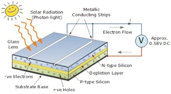 | ||
| Fig. 1 A schematic diagram showing the construction and working of solar panels. Reproduced with permission4 (taken from the website) Copyright 2024. | ||
However, solar photovoltaic (PV) modules deployed for power generation are usually susceptible to many environmental factors, including solar radiation levels, wind speed and direction, ambient temperature, humidity and atmospheric dust.5,6 The solar panel surface requires a thin coating to avoid the loss of incident light energy due to reflection. The accumulation of dust, grime, pollen and other particles on solar panel surfaces leads to a decline in efficiency. Therefore, maintaining dust-free surfaces through routine cleaning or employing a self-cleaning surface coating is imperative to achieve optimum performance.7
Dust accumulation is a common issue in solar panel systems, which reduces the power conversion efficiency of solar cell modules by 10–20% annually.8,9 The effect of dust on the efficiency loss of solar panels in various countries is shown in Fig. 2. To maintain efficiency, solar panels should be cleaned routinely, which is labour-intensive for large solar panel arrays.10 Cleaning dusty panels with detergents can be laborious, time-consuming, and costly, and comes with the possibility of corrosion of the solar panel frame.9,11 One of the approaches for addressing the problem of dust deposition is to make the surface extremely hydrophobic or superhydrophobic so that the dust particles repel off the surface. The word ‘superhydrophobic’ has now become well-known and refers to extreme hydrophobicity and the tendency of a surface to repel water droplets. Several efforts have been made to mimic the superhydrophobic structures originating in nature (for example, lotus leaves), so that artificial superhydrophobic surfaces could be prepared that exhibit self-cleaning properties.12–14 In the literature, various types of materials and methods are reported to achieve superhydrophobicity, but for solar cell applications, it is additionally required that the coatings have high light transmission. Analogous to superhydrophobic coatings, superhydrophilic coatings are also reported to impart self-cleaning properties to the solar panel.1,15
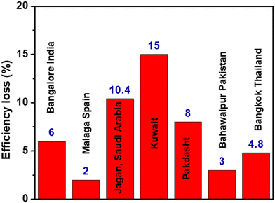 | ||
| Fig. 2 Effect of dust on solar panel efficiency.19 | ||
In order to achieve high-performance solar cells, it is imperative to incorporate an anti-reflecting surface.15 The reflection of light on solar panels’ surfaces decreases the light absorption capacity of solar cells, thereby reducing their overall performance. Provided that the reflection of bare silicon solar cells can exceed 30%,1,7,9 the application of anti-reflective coatings becomes essential to enhance the amount of absorbed light. Silicon nitride or titanium oxide is commonly used for thin anti-reflective coatings.1,16 Anti-reflective coatings on solar panels are quite similar to coatings used on other devices, such as camera lenses.17 Presently, anti-reflective coatings are not limited to solar cells but can also be applied to the glass surface (superstate) of solar panels. Anti-reflective coatings on the solar panels’ glass enhance light transmittance, consequently increasing the overall efficiency of the photovoltaic module.10,15 Moreover, anti-reflective coatings are necessary to ensure the safety of drivers. Solar panels located near airports without anti-reflective coatings pose the risk of potentially blinding pilots.15,18
Fog is another parameter that disturbs the efficiency of the panel cells. Anti-fogging coatings used for this purpose are often nanolayer coatings, which prevent fogging on the surface on which they are coated by inhibiting the condensation of water on the surface.20,21 At the same time, if the surface is superhydrophobic, it will be advantageous as the condensed water will roll off and the solar panel surface will remain clean.
Furthermore, solar panel coatings with self-healing properties will also be beneficial. The self-healing properties are governed by the automatic repair of damage or cracks ascribed to structural failure or aging and due to thermal, electrical, mechanical, and harsh weather conditions.22–24 This will help to enhance the life span and long-term durability and reduce the local maintenance cost of the solar panel coatings.25–27 The self-healing solar panel coating is a promising area of research. Various approaches are reported in the literature, which are discussed in this review.
Achieving mechanical robustness and durability in a coating while preserving its transparency and superhydrophobicity poses a formidable challenge within the framework of a facile and cost-effective material technology. To achieve maximum efficiency, the primary requirement for solar panel coatings is very high transparency. In addition to high transparency, solar panel coatings should exhibit versatile multi-functional properties such as anti-fogging, anti-reflecting, and self-cleaning performance, as described in Fig. 3. Furthermore, they should demonstrate durability, sustained efficiency, mechanical stability, scratch resistance, adhesion properties, corrosion resistance, weather resistance, cost-effectiveness, and thermal stability. In this context, this review emphasizes the design of next-generation high-performance solar panel coatings, aiming to achieve a synergistic combination of properties that enhance both the performance and lifespan of solar panels.
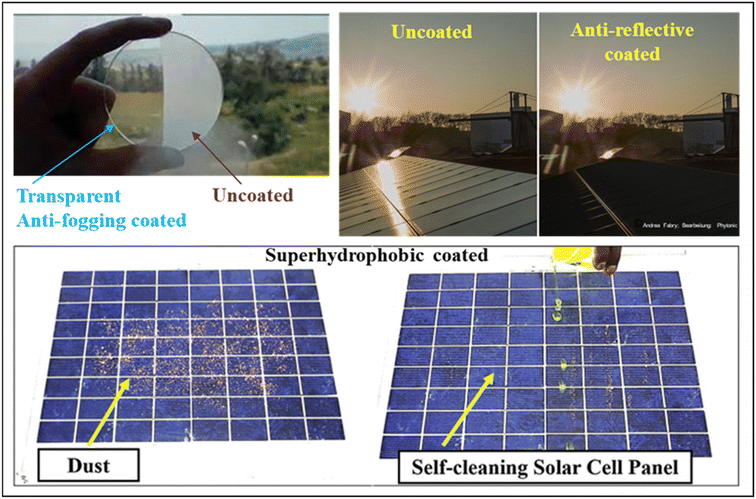 | ||
| Fig. 3 Pictorial representation of a solar panel coating showing multi-functional properties. Reproduced with permission10,28,29 from Elsevier, Copyright 2019. | ||
Anti-reflective coatings
Theoretical aspects of antireflection based on nanostructure arrays
An anti-reflection (AR) coating is a thin film coating applied to an optical surface to reduce the reflectance of that surface. In traditional layered antireflection (AR) coatings widely employed in optical and optoelectronic devices, the fundamental principle involves a single-layer dielectric thin film with a low refractive index (n) deposited on a substrate of higher refractive index (ns), where ns > n.30 This configuration adheres to the film interference law (Fig. 4), generating two interfaces within the thin film. These interfaces give rise to two reflected waves, wherein destructive interference occurs when these waves are out of phase. Minimal reflection loss is achieved through optimization of the thin film's thickness and refractive index, which are wavelength-, angle-, and polarization-dependent.31 Consequently, single-layer AR coatings effectively mitigate reflection at specific incident light wavelengths, angles, and polarization.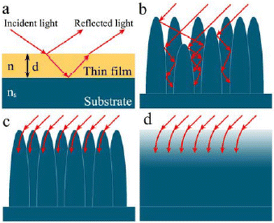 | ||
| Fig. 4 (a) Propagation of incident light through a single layer film on substrates (ns > n). (b) Multiple internal reflections of incident light in a microstructure array. (c) Interaction of incident light with the sub-wavelength-size nanoarray. (d) Schematic illustration of the refractive index changes corresponding to (c). Reproduced with permission30 RSC 2015. | ||
AR coatings based on micro- and nanostructure arrays, inspired by “moth's eye” structures, offer an alternative approach to reducing reflectance.17 The interaction between these arrayed structures and incident light varies depending on the characteristic scale of the structures.
If the size of the individual unit is much larger than the wavelength, referred to as macrostructure units, the incident light is primarily reflected and scattered after partial absorption. However, if the depth and spacing between individual structural units match the wavelength of light, light rays are trapped in the gaps, leading to multiple internal reflections (Fig. 4b).30 Thus, the incident radiation is absorbed, reducing the reflection in the visible range to a very low level.
In contrast, when the AR structures have dimensions smaller than the wavelength, i.e., in the sub-wavelength or nanoscale range, a different mechanism comes into play. Light is insensitive to the AR structures and tends to bend progressively, behaving as though the AR surface possesses a gradient refractive index (Fig. 4c and d).30 Even when the angle of incidence changes, the coating maintains a relatively smooth refractive index gradient in the direction of the incident light, thereby suppressing reflection across a broad range of wavelengths.
Additionally, natural light exhibits varying degrees of polarization, including s-polarization and p-polarization, where the electric field is perpendicular and parallel to the plane of incidence, respectively. For sub-wavelength-scale or nanoscale arrays with a smoothly graded refractive index from air to substrate, the reflection of light, regardless of its polarization, can be minimized. This is because the transmission of light with different polarizations is insensitive to media with minimal refractive index disparity.17,30 Therefore, AR coatings based on nanoscale arrays with a gradient refractive index can achieve broadband, omnidirectional, and polarization-insensitive AR performance, which is superior to traditional layered AR coatings.
In the case of solar cells, AR coating facilitates a reduction in reflection loss, an increase in absorption, and improves the power conversion efficiency. Commonly, various materials such as SiO2, TiO2, MgF2, Si3N4, and ZrO2 are used to achieve anti-reflection properties in coating materials.1,15
Jalali et al. have reported a sol–gel solution of ZnO nanoparticles, layer deposited on a silicon substrate for application as an anti-reflective layer for solar cells.32 This ZnO-based coating improved the efficiency of the cell from 5.29% to 9.19%. Silicon nitride (SiNx) is also known for AR coating purposes due to its high refractive index, which varies between 1.9 and 2.3, by varying the deposition parameters, along with its cost-effectiveness.33,34 Maiga et al. optimized the performance of solar cell panels with double-layer SiNx/SiNx AR coating by variations in the angle of incidence.35
Self-cleaning coatings
Solar panels are prone to dirt accumulation, particularly in areas with dust storms, which adversely affects their power output. The relationship between the dust deposition density on a coated surface and the average reduction in transmittance is plotted in Fig. 5. This shows that the reduction in transmittance is directly caused by the accumulation of dust on the coated glass surfaces. The decrease in transmittance is directly correlated with the efficiency of solar panels.6,36–38 Self-cleaning coatings provide an effective solution by reducing the need for frequent manual cleaning. These coatings achieve self-cleaning through surface designs that are either superhydrophobic or superhydrophilic.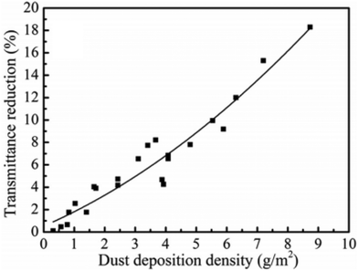 | ||
| Fig. 5 Effect of transmittance w.r.t. dust deposition density.6,38 Reproduced with permission from ref. 41, ScienceDirect, 2024. | ||
Self-cleaning superhydrophobic coatings
Superhydrophobic surfaces are characterized by a water contact angle (WCA) of more than 150°. The development of superhydrophobic surfaces is mostly inspired by the lotus leaf effect, where water rolls off as spherical droplets due to a rough hierarchical micro/nanostructure of the leaf, as depicted in Fig. 6.39,40 The rolling water drops collect dust from the rough superhydrophobic surface, resulting in a self-cleaning phenomenon. In addition to high WCA, a superhydrophobic surface exhibits low contact angle hysteresis (<10°), low sliding angle (<5°) and high stability of the Cassie model state (shown in Fig. 4).8,40,41 | ||
| Fig. 6 Illustration of the behaviour of water droplets based on the (a) Lotus effect, (b) Wenzel model, (c) CB (Cassie–Baxter) model, and (d) superhydrophilic behavior.11,15 | ||
The lotus leaf is the first biological surface that inspired a superhydrophobic phenomenon. The superhydrophobicity and self-cleaning properties of lotus leaves are contributed by both rough micro and nanosurface structures. Surface structures involve a hierarchical array of micro-papillae, nano-wax clusters, and nano-wax tubules as roughness factors on the lotus leaf surfaces.12 The combination of dual scale roughness in lotus leaf structures entails a rough structure of ∼10 μm and a fine structure of ∼100 nm that leads to extreme surface hydrophobicity with a WCA ≤161° along with a CA hysteresis of 2°. According to the Cassie–Baxter (CB) state (Fig. 6), water suspension above these hierarchical structures of the lotus leaf is in a non-equilibrium thermodynamic state and rolls spontaneously, resulting in low hysteresis.42 Surface wettability on flat surfaces was determined by measuring the contact angle (CA), θ, of water droplets by applying Young's equation:
cos![[thin space (1/6-em)]](https://www.rsc.org/images/entities/char_2009.gif) θ = γSV − γSL/γLV θ = γSV − γSL/γLV | (1) |
cos![[thin space (1/6-em)]](https://www.rsc.org/images/entities/char_2009.gif) θw = r θw = r![[thin space (1/6-em)]](https://www.rsc.org/images/entities/char_2009.gif) cos cos![[thin space (1/6-em)]](https://www.rsc.org/images/entities/char_2009.gif) θ θ | (2) |
This water suspension causes a non-equilibrium state, but later the droplet starts sliding immediately. The movement of the droplet was termed contact angle hysteresis (Δθ), and the value of Δθ was measured from the differences between the advancing angle, θa, and the receding angle, θr. Superhydrophobic surfaces could achieve low Δθ values due to large roughness factors and chemical heterogeneity. Different phases from chemical heterogeneity contribute to a large apparent contact angle as described by the CB equation:41
cos![[thin space (1/6-em)]](https://www.rsc.org/images/entities/char_2009.gif) θc = f1cos θc = f1cos![[thin space (1/6-em)]](https://www.rsc.org/images/entities/char_2009.gif) θ1 + f2cos θ1 + f2cos![[thin space (1/6-em)]](https://www.rsc.org/images/entities/char_2009.gif) θ2 θ2 | (3) |
![[thin space (1/6-em)]](https://www.rsc.org/images/entities/char_2009.gif) θc = f(1 + cos
θc = f(1 + cos![[thin space (1/6-em)]](https://www.rsc.org/images/entities/char_2009.gif) θ) − 1.
θ) − 1.
The mechanisms of anti-soiling are defined by the concepts of surface morphology and hydrophobicity. Droplets could readily roll on a superhydrophobic surface to carry the dust and dirt away, thereby demonstrating anti-soiling performance. Water droplets play a vital role in the cleaning process of dust particles. However, if there is not enough rainwater in some places, such as deserts, the anti-soiling ability of superhydrophobic surfaces is the other case.38,44 In Fig. 7, transparent nano-coatings with hydrophobic surfaces exhibit roughness and low energy, leading to the repulsion or detachment of dust particles, whereas smooth surfaces and high surface energy such as bare glass allow the dust particles to remain adhered to the surface.
 | ||
| Fig. 7 Schematic representation of the self-cleaning mechanism of the dust particles on the hydrophobic surfaces. Reproduced with permission38 from Elsevier. | ||
For solar panel coatings, achieving high transparency is also required, along with surfaces featuring superhydrophobic roughness and low wettability. These transparent superhydrophobic surfaces can be achieved by an appropriate selection of materials combined with surface modelling to create hierarchical micro- and nanostructures required for superhydrophobicity.1,41 Self-cleaning can also be achieved by making the surfaces superhydrophilic, where water drops spread over the surface and form a film of water. During this process of spreading, the contaminants on the surface are washed away.
The coatings can be prepared by various methods such as sol–gel, dip-coating, spin-coating, thermal evaporation, chemical vapor deposition, RF or DC magnetron sputtering, electron beam, spray pyrolysis, and electro-spinning.19 In addition to these methods, serigraphy and lithography methods are also used. Nano-porous superhydrophobic coatings can be obtained by spin coatings, sputter coating, hydrothermal synthesis, layer-by-layer deposition etc., while microstructures can be fabricated by polymerization, lithographic and electrochemical methods.19
Self-cleaning superhydrophobic and anti-reflective coatings for solar panels
Self-cleaning coatings for application in solar panels should exhibit both superhydrophobicity and high transmittance properties. Typically, achieving superhydrophobic film coatings involves introducing high surface roughness, which conflicts with maintaining high transmittance in the film coatings. Consequently, an optimal balance between surface roughness and high transmittance is crucial for optimum performance. Various approaches and materials have been explored to achieve transparent self-cleaning superhydrophobic coatings specifically tailored for solar panels. Numerous materials have been proposed for the fabrication of superhydrophobic coatings including fluorocarbons, silicones, and organic polymeric materials such as polystyrene, polymethyl methacrylate, polyurethane, polycarbonate and poly(vinyl chloride). The superhydrophobic surfaces can also be achieved by using inorganic materials including ZnO and TiO2. This section delves into the discussion of transparent superhydrophobic polymer coatings designed for applications in solar cells.Ko et al. demonstrated the mechanistic investigations of the relationship between hydrophobicity and transmittance.45 The developed superhydrophobic silica coating layers exhibit contact angles above 150, light transmittance above 90%, and strong weather resistance via three strategies: (i) hexadecyltrimethoxysilane-modified SiO2 (H-SiO2) particle agglomeration in colloidal coating solutions, and the formation of (ii) two-dimensional (2D) mud-crack patterns and (iii) three-dimensional (3D) micro-bumps. First, particle agglomeration was optimized in a mixed solution of water and ethanol with a relative permittivity of ε = 48.0. Second, high transmittance and fully-covered hydrophobic properties were achieved from the silica coating layers with 2D mud-crack patterns mixed with solvents of ethanol (ε = 24.3) and water (ε = 78.4) with different water volume fractions (fw = 0.08, 0.25, 0.44, 0.65, and 0.88). The relative permittivity of the mixed solvents was calculated using eqn:
| εm = f1ε1 + f2ε2 |
The reason might be that the choice of mixed solvent evaporated with rapid interface descending rates at higher temperatures, enhancing the capturing force to integrate agglomerated H-SiO2 nanoparticles. These small patterns could provide a large number of rough boundaries per unit area to create strong hydrophobicity in the H-SiO2 coating layers. Hydrophobicity was improved with a CAmax from 116.4° to 131.9° by decreasing the temperature from 70 °C to 25 °C. As shown in Fig. 8, to achieve superhydrophobicity in the HSiO2 coating layers for self-cleaning, three-dimensional (3D) micro-bumps were adopted as the top layer over the mud-crack patterns by two-step brush painting of 1 wt% H-SiO2 colloidal particle solutions with different fw values (0.08, 0.44, and 0.88). Painting the H-SiO2 bottom layers using a soft brush resulted in 2D mud-crack patterns; however, the CAmax of 131.9° was insufficient for a self-cleaning superhydrophobic surface. A hard brush was then used to paint the H-SiO2 top layers. The resultant 3D micro-bumps exhibited irregular shapes and different sizes that enhance H-SiO2 layering on the surface, as shown in Fig. 9. The SEM images with the roughness profiles in Fig. 9 reveal heterogeneous bumps with a height of 2 μm–11 μm when fw = 0.44. In contrast, H-SiO2 coating layers with fw = 0.08 and 0.88 had smooth surfaces, with the average roughness values of Ra = 0.08 and 0.23 lm compared to Ra = 0.68 lm for fw = 0.44. The roughness profiles indicated that insufficient and excess particle agglomeration will produce a smoother coating without bumps at fw = 0.08 and 0.88 (Table 1).
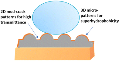 | ||
| Fig. 8 Schematic illustration for 2D and 3D micro-patterns for high transmittance and superhydrophobic coatings.45 | ||
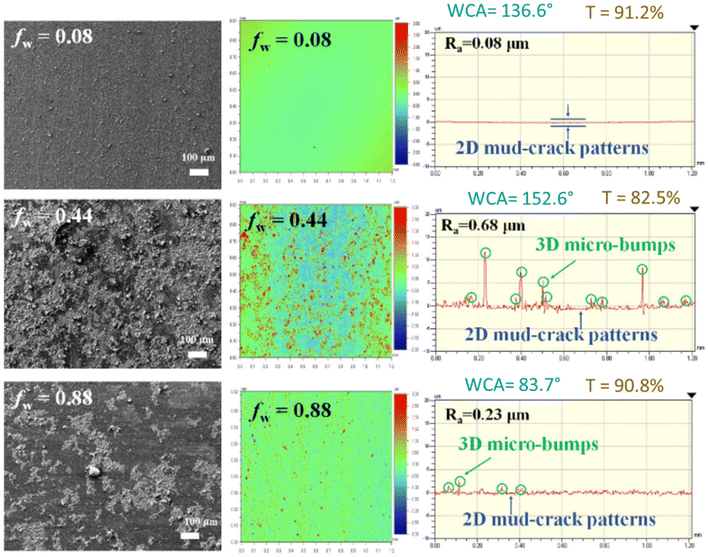 | ||
| Fig. 9 Two-step brush-painted superhydrophobic H-SiO2 layers, showing FE-SEM images for surface morphology, surface profiles with average roughness, water contact angles, and transmittance (%).45 | ||
| Materials | Transparency | WCA | Mechanical robustness | Ref./year |
|---|---|---|---|---|
| PDMS, DMS, Si nanoparticles | 92.4% | 168° | A WCA of 110° after 5 tape peeling cycles | 42/2020 |
| PU/FAP/SiO2 | 88% | 159° | A WCA of 110° after the sandpaper abrasion test (300 cm, 25 cycles) at a load of 200 g (an area of 3 × 3 cm2) | 39/2021 |
| VTEO/SiO2/MTSR | 80% | 154° | A WCA of 135° after the ultrasonic resistance test (60 min) | 40/2020 |
| Fluoro silane/siloxane/epoxy-amine | 93.6% | 160° | 36/2013 | |
| ZnO/SiO2/epoxy resin | 94% | 172° | A WCA of 152° after the sandpaper abrasion test (100 cm, at a pressure of 10.5 kPa) | 45/2019 |
| TEOS/MTES/EP | 90.5% | 167° | A WCA of 140° after the sandpaper abrasion test (1460 cm, at a pressure of 2.5 kPa) | 41/2018 |
| PUA/PFPE/Al2O3 | 93.6% | 156° | 50/2019 |
The best superhydrophobicity on PET substrates was achieved at fw = 0.44, with a high CAmax = 152.6° and co-existing 2D mud-crack patterns and 3D micro-bumps, as depicted in Fig. 9. As shown in Fig. 9, the HSiO2 coating layers exhibited transmittance values of 91.2%, 82.5%, and 90.8% respectively at fw = 0.08, 0.44, and 0.88 compared to 92.4% for the uncoated PET substrate. The PET-excepted transmittance of 90.2% at fw = 0.44 is acceptable for self-cleaning solar cell panel coating. The thickness range of the H-SiO2 coating layers was found to be 1 μm–11 μm, which is the total height of 2D mud cracks and heterogeneous 3D micro-bumps.
Silicon-based superhydrophobic coatings
Siloxane- or silicate-based coatings are well developed for superhydrophobic performance due to their easy functionalization, good reactivity, crosslinking ability, accessibility, and cost-effectiveness. They provide outstanding optical and mechanical properties, ease of controlling surface morphology, and readily available hydroxyl (OH) functional groups for further chemical modification.46 Moreover, siloxane-based coatings promote interfacial adhesions, along with scratch, scrub, abrasion, and corrosion resistance.Achieving superhydrophobic surfaces requires not only reducing surface energy but also introducing appropriate surface roughness or morphology. Wang et al. have developed a superhydrophobic silica film by the dip-coating method using tetraethoxysilane (TEOS) as a precursor and trimethylethoxy silane (TMES) as a modifier. In their process, the condensation reactions take place between Si–OH and HO–Si–(CH3)3 through the hydroxyl groups, allowing the –Si–(CH3)3 bond to form on the surface of nano-SiO2 particles via Si–O–Si bonds. Once all –OH groups on the surface of nano-SiO2 particles are completely replaced with –Si–(CH3)3 groups, the nano-SiO2 particles become fully encapsulated by these groups. This encapsulation prevents further condensation with new Si–OH groups, thereby halting the growth of the nano-SiO2 particles. By varying the particle sizes in the SiO2 sol, the researchers created films with polydisperse concave–convex structures, combining chemical modification with sol mixing to achieve the desired roughness. These silica films exhibited a high transmittance of 94.8%, a water contact angle (WCA) of 158°, and a root-mean-square (RMS) roughness ranging from 1.86 to 5.41 nm.47
Ji et al. have developed a hybrid coating based on fluorous and siloxane along with amine and epoxy functionalities, which shows a high transmittance of 93.6% and a WCA of 160° through sol–gel/spin-coating technology. A transparent super-hydrophobic coating was obtained by curing based on the combined effect of Si–O linkages, epoxy, and amino groups. The combination of nano and microstructure morphologies plays a key role in superhydrophobicity.48
Achieving transparency in superhydrophobic surfaces is particularly challenging because the roughness required for superhydrophobicity typically reduces transparency. Superhydrophobic surfaces rely on surface roughness to maintain a high water contact angle, but this roughness can scatter light and diminish optical clarity. One common approach to overcoming this challenge is to fabricate a porous film with controlled roughness on a substrate to achieve a balance between superhydrophobicity and high transmittance. A material with a low surface energy that contains fluorinated/siloxane or –CH3 groups is deposited on top of a porous film to impart superhydrophobicity. Wang et al. used a layer-by-layer (LBL) deposition method involving poly(allylamine hydrochloride) and poly(acrylic acid) to create a transparent, superhydrophobic surface.49 Since the low-energy molecule layer is only a few nanometres thick, it minimally affects transmittance. They prepared a superhydrophobic sol–gel by hydrolyzing tetraethoxysilane (TEOS) and reacting it with hexamethyldisilazane (HMDS), introducing both hydrophobic –CH3 groups and the necessary roughness. A highly transparent coating results in a surface with a water contact angle (WCA) of 164°, a contact angle hysteresis (CAH) of 1.8°, and a transmittance of 96%. Despite the inherent difficulty in achieving transparency on rough surfaces, this method demonstrates a successful balance between optical clarity and superhydrophobicity.
Prado et al. developed a multi-functional anti-reflecting coating with a transmittance of 95.9% based on silica nanoparticles prepared by the sol–gel method using tetraethyl orthosilicate (TEOS) and Pluronic F127.50 The anti-reflective coated glass was developed using mesoporous TiO2/SiO2 layers. The unique morphological arrangement of nanostructured inner SiO2 and outer TiO2 layers (thickness 16 and 30 nm, respectively), along with an increased surface area, resulted in enhanced self-cleaning performance along with high photocatalytic activity.51 Particularly, photocatalytic outer TiO2 surfaces absorb sunlight/indoor light to decompose dirt and other impurities present on the surface, achieving 25–30% degree of degradation.15
In another study, Zhou et al. reported a durable superhydrophobic coating formed by double crosslinking through thermal condensation and UV curing.52 A nano-SiO2 layer with a uniform hierarchical rough structure was created on the surface with a compact gap between the bulges. His structure significantly reduced the contact area between water droplets and the surface, creating an “air cushion” consistent with the Cassie–Baxter model. The modified nano-structure coatings exhibited a transmittance of 80%, a WCA of 154°, and a rolling angle below 5°, with the mass fraction of the vinyl-SiO2 nanoparticles at 1.2 wt%.52 The hydrophobic methyl vinyl silicone resin is used as the matrix material where the oxygen inhibition layer is an active site.
Li et al. developed a transparent superhydrophobic coating with a transmittance of 90.5% and a WCA of 167° based on a silica/epoxy resin bilayer coating system.53 Superhydrophobicity was attributed to the low surface energy –CH3 groups grafted onto the surface of SiO2. Siddiqui et al. demonstrated a transparent superhydrophobic surface fabricated via one-step thermal oxidation using silicone grease (Dow Corning high vacuum grease), i.e., a mixture of PDMS, DMS monomers, and Si nanoparticles. The greased surface was heated in a furnace at 400 °C for 60 minutes, resulting in a sponge-like porous structure of amorphous silica nanoparticles with a diameter of around 20 ± 2.2 nm, leading to a WCA of 168° without compromising high transmittance of 92.4%.54
Recently, soft imprint lithography has gained significant attention for fabricating micro- or nano-patterns onto UV-curable poly-dimethylsiloxane (PDMS) polymers. PDMS has various advantages such as low free surface energy, flexibility, transparency, and hardness, owing to its simplicity, cost-effectiveness, and tenability. NOA63 (Norland Optical Adhesive 63 is a clear, colorless, liquid photopolymer), which cures when exposed to ultraviolet light polymers, is widely used as an ARC owing to its similar RI of 1.56 to the ultraviolet light polymers with almost no absorption in the wavelength windows of 350 and 1800 nm. The PDMS/NOA63 conical nanograting pattern coatings displayed a hydrophobic surface with a WCA of 112° and a transmittance of 93.2%.
Fluorinated superhydrophobic coatings
Fluorinated or fluorous-based components provide both hydrophobicity and oleophobicity. Fluoropolymers have found wide applications in composite materials, films, coatings and paints.55 Fluoropolymers have been extensively used in many high-technology applications, such as aeronautics, aerospace, solar panels, satellite/radar dishes, and electronics, due to their high resistance to harsh weather conditions and exceptional inertness to a wide range of chemical environments due to their outstandingly strong C–F bonds, low polarizability, and weak intermolecular van der Waals interactions.25,56,57 The presence of fluorine groups in a coating material led to both self-cleaning and the development of AR properties due to its low surface energy and relatively low RI.58 Yang et al. developed fluorosilane-modified silica nanoparticles (F-SiO2 NPs) and achieved superhydrophobic transparent coating by the assembly of the nanoparticles via one-step spin-coating as illustrated in Fig. 10.59 The synthesis of these fluorosilane functionalized silica NPs involved reacting the hydrophilic silica NPs with (heptadecafluoro-1,1,2,2,-tetrahydrodecyl)dimethylchlorosilane (HDFTHD), as shown in Fig. 10. The F-SiO2 NPs formed stable dispersion only in fluorinated solvents. Hence, Novec 7300 and decafluoropentane were used for spin-casting and dip-coating, respectively. At an F-SiO2 NP concentration of ≥0.8 wt%, the coated surface exhibited a transition from the Wenzel state to the Cassie–Baxter nonwetting state, achieving superhydrophobicity with an advancing water contact angle (WCA) greater than 150°, while maintaining 95% transmittance. The nanoparticle concentration increased, and the assembly transitioned from random, non-close-packed (0.1 wt% and 0.4 wt%) to nearly close-packed (≥0.8 wt%), fully covering the substrate (Fig. 10c). Additionally, the 0.8 wt% NP film had a few second-layer NPs covering the first layer, while the 1.2 wt% NP film showed a more pronounced double-layered structure. Atomic force microscopy (AFM) results revealed that surface roughness (rms) decreased with increasing NP coverage, from 51.20 nm at 0.1 wt% to 49.70 nm at 0.4 wt%, 25.80 nm at 0.8 wt%, and 13.90 nm at 1.2 wt%. They further demonstrated this coating on polymeric substrates, where oxygen plasma and vapor deposition of a hydrophobic passivation layer (e.g., fluorosilane) are not desirable. Lei et al. developed a superhydrophobic coating system based on fillers and polymer matrices by mixing colloidal silica with a cross-linkable fluoropolymer at ambient temperature followed by spraying methods.60 A fluorinated ethylene-(hydroxyl-alkyl)vinyl ether (FEVE) copolymer was designed as a polymer matrix due to its good hydrophobicity, mechanical properties, weatherability, and solubility. Functionalized colloidal silica was used as a filler. Superhydrophobicity (a water contact angle of ∼155° and a rolling angle of ∼1°) and desired integrity were observed in the coatings with fluorinated particles (with a dimension of either 340 or 1450 nm) at an optimal particle volume fraction of 60%. A combination of fluoro-functionalized particles with sizes of 340 nm and 1450 nm, mixed at 60% volume, created a micro-patterned surface roughness, contributing to the superhydrophobicity of the surface. Hybrid superhydrophobic coatings based on polyurethane/fluorinated acrylic co-polymer/silicon dioxide (PU/FAP/SiO2) were fabricated on glass substrates through a single-step coating process by the Jiang group. This coating exhibits a transmittance of 88%, a WCA of 159° and a rolling angle of 3°.51 Gong et al. prepared a durable self-cleaning surface that exhibits excellent superhydrophobicity/oleophobicity (WCA 172°) and high transmittance of 94% by treating the nanoparticles with 1H,1H,2H,2H-perfluorodecyltriethoxysilane (FAS-17).61 Epoxy resin is used as an adhesive material to improve the wear resistance of the surfaces. The desired superhydrophobicity is achieved by high surface roughness generated by ZnO and SiO2 nanoparticles, in combination with low surface energy fluorinated siloxane (FAS-17). The surface exhibits a maximum roughness of 0.825 μm, which is attributed to the agglomeration and distribution of ZnO and SiO2 nanoparticles on the surface. The roughness was observed to increase initially as the mass of SiO2 increased and subsequently reduced. A maximum roughness was achieved at a mass ratio of 3![[thin space (1/6-em)]](https://www.rsc.org/images/entities/char_2009.gif) :
:![[thin space (1/6-em)]](https://www.rsc.org/images/entities/char_2009.gif) 3 for ZnO/SiO2.
3 for ZnO/SiO2.
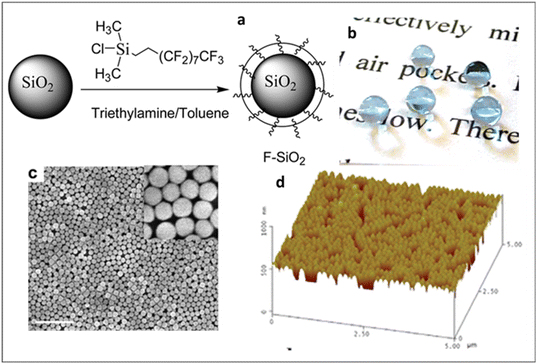 | ||
| Fig. 10 (a) Schematic illustration of the synthesis of fluorosilane-coated silica nanoparticles, (b) optical photographs of water droplet-coated polyester fabric, and (c) surface morphology from SEM and (d) AFM images. Reproduced with permission from ref. 59, ACS, Copyright 2012. | ||
Organic polymer-based superhydrophobic coatings
Most of these super-hydrophobic surfaces were prepared by using precursor materials based on fluorous and/or silicon.62,63 Super-hydrophobic surfaces from a commonly hydrophobic material without the addition of low surface-energy ingredients are commercially important. Apart from these, organic-based polymeric materials are also developed for superhydrophobic surfaces. Han et al. have developed super-hydrophobic surfaces based on semicrystalline low-density polyethylene (LDPE).64 The porous surface, with hierarchical micro- and nanostructures having floral designs, exhibited a water contact angle of 173°. Li Xinhong et al. developed a super-hydrophobic (WCA 172°) poly(vinyl chloride) surface and films that maintained their super-hydrophobicity upon coming into contact with acid, alkali, or salt solutions. The superhydrophobicity of the material is a result of its unique surface microstructure, which resembles that of a lotus leaf. This microstructure is achieved by a series of processes including diffusion, tension break during solution casting, micro- and nano-phase separation, and subsequent nano-phase separation and solidification.65 Choi and Huh prepared a biomimetic anti-reflective, self-cleaning coating by combining UV-assisted molding with subsequent hydrophobization of nanoparticles through a single-step replication process for light harvesting applications in organic solar cells.66 Polyurethane acrylate (PUA) functionalized prepolymer with a perfluoropolyether (PFPE) backbone was used as a UV-curable precursor anchored on Al2O3 nanoparticles. The fabricated solar cell shows superhydrophobicity with a WCA of >156° due to multi-scale hierarchical surface morphology and low surface energy of fluorine. The transmittance was found to be 92% over a visible region using ITO as a substrate for solar cell devices due to the high reflective power of ITO.Wong et al. developed a low-cost synthesis of large-scale ultradurable superhydrophobic coatings by hasty template-free micro–nano texturing of interpenetrated polymer networks (IPNs) using spray coatings.67 A highly transparent texture of soft-yielding marshmallow-like pillars with ultralow surface energy was attained by successive spraying of a novel polyurethane-acrylic colloidal suspension and a superhydrophobic nanoparticle solution. The colloidal suspension was prepared in two segments, a PMMA component in acetone and a PU component in xylene. Upon mixing both solutions, each component cross-linked simultaneously, which results in a colloidal suspension of PU-PMMA. The transparent self-healing and self-cleaning surfaces exhibit a WCA of 163° with superior abrasion, chemical, and UV resistance.
Metal oxide-based superhydrophobic coatings
Metal oxide-based nanostructures are also known for superhydrophobic and high transmittance coating applications. Li et al. have developed a superhydrophobic ZnO/Zn surface with nanowires and nanobelts structures with a WCA of 157°.68 The superhydrophobic interconnected ZnO nanobelts and nanowires structure was prepared by Ar plasma activated Zn vapor deposition and then followed by a low-pressure-air (5 Pa) thermal oxidation at 350 °C. Patil et al. have described a zinc oxide (ZnO) based superhydrophobic thin film with a transparency of 85% and a WCA of 154°. The thin film was prepared by the spray pyrolysis technique (SPT) onto the glass substrates at 450° from an aqueous zinc acetate precursor solution.69 Xiong et al. have developed a ZnO-based micro-/nano-hierarchical structure fabricated by etching of thin films and growth of nanorods, with transparency above 90% and a WCA of 160°.70 Li et al. have described superhydrophobic (WCA 151°) ZnO micro–nanostructured films using chemical vapor deposition.71 Hiralal et al. demonstrated the ZnO nanowire-based ARCs for organic PV solar cells and found that the coating imparts additional benefits to the solar cell such as a lower rate of degradation and also decreased absorption of UV radiation.72 A combination of ZnO nanowire and air-filled porous surface structure (Cassie-Baxter effect) resulted in a superhydrophobic surface with WCA 152° and transmittance above 90%. ZnO is a photocatalytic semiconductor that catalyzes redox reactions in the presence of water and oxygen, thereby facilitating the breakdown of organic molecules on its coating surface.72 Typical materials such as siloxane, fluorinated, metal oxide, and organic polymer-based hybrids utilized for superhydrophobic coatings are illustrated in Fig. 11.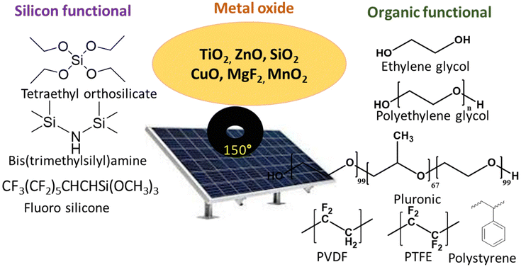 | ||
| Fig. 11 Monomers or polymers are used in solar panel coatings through sol–gel chemistry.10,11,15 | ||
Superhydrophilic self-cleaning coatings for solar panels
Self-cleaning performance can also be achieved by making the surfaces extremely hydrophilic, also known as superhydrophilic (a WCA of as low as ∼5°).15 Superhydrophilic surfaces work by spreading water into a thin film that washes away contaminants. The lower the WCA, the higher will be the spreading areas of water droplets on surfaces, which in turn carry dirt in the flow-through. The coatings of this type of behaviour are more appropriate for solar panel applications since they are smoother, unlike rougher superhydrophobic surfaces. The smoother coatings shine more than the rougher ones, and hence, do not pay much to the reflection loss and ultimately increase light transmittance and energy conversion efficiency. In other words, superhydrophilic coatings are proven to be beneficial for solar panels in two ways: firstly, self-cleaning performance and secondly, protecting PV modules from reflection loss.15 Therefore, numerous studies have reported fabrication strategies of superhydrophilic coatings for solar panel applications.Surface roughness and porosity play a vital role in the generation of superhydrophilic coatings. Some surface microstructures and nanoscale porous structures can show superhydrophilicity. TiO2 nanoparticles are generally used to obtain superhydrophilic coatings.73 Designing superhydrophilic surfaces is challenging and the fabrication methods are typically substrate-specific. Rico et al. have developed superhydrophilic TiO2 thin films (300–500 nm thick) by physical vapor deposition in an electron evaporation system.74 This process controlled the porosity of the film, resulting in crystalline microstructures. A superhydrophilic surface was achieved by the fabrication method of hydrothermal treatment of anatase TiO2 nanosheet films by Hosono et al.75 Similarly, Liu et al. achieved a superhydrophilic surface using hydrothermal treatment of slide glass at 180 °C for 24 h.76 These surfaces comprised a predominant three-dimensionally interconnected porous structure together with minor network structures and displayed a WCA close to 0°. An ultrathin, colorless, and transparent superhydrophilic surface was developed by Li et al. using the coordination complexes of natural phytic acid and Fe(III) ions.77 These superhydrophilicities of the surfaces are partly ascribed to the high density of phosphonic acid groups. Bai et al. fabricated mesoporous triple-layered SiO2/Bi2O3/TiO2 thin films on glass substrates using a sol–gel/spin-coating method.78 Their self-cleaning performance was evaluated by tracking the photocatalytic removal of stearic acid. Particularly, photocatalytic hydrophilic surfaces use sunlight/indoor light to decompose dirt and other impurities found on the surface. The self-cleaning process is mainly dependent on the reaction of photocatalytic surfaces or materials with ultraviolet light to split the organic dirt.79–81
These mesoporous superhydrophilic and photocatalytically active thin films could be used as anti-fogging films even in the dark or on rainy days which can be a self-cleaning material when exposed to weak UV light irradiation. It is also stable towards 5 wt% H2SO4 at room temperature for 24 h, retaining superhydrophilicity and photoactivity performance. Thongsuwan et al. developed a high transmittance ≥90% superhydrophilic (WCA ≤ 40°) coating prepared by the sparking process for solar panels based on titanium nanoparticles.82 During sparking, electrons and ions formed from neutral air molecules drift toward the anode and cathode, respectively. The bombardment of high-energy electrons and ions melts the metal tips. Hence, the nanodroplets are nucleated, which move toward the substrate and oxidize in atmospheric air. A schematic of the nucleation and growth of the nanostructures is given in Fig. 12a.82 The outdoor solar panel was set at Chiang Mai University (18.801468, 98.956036) facing south with a tilt angle of 19° for performance testing. The behaviour of rainwater droplets on the coated and uncoated surfaces showed that rainwater spread across the coated panels, whereas the droplets were formed on the uncoated surfaces as illustrated in Fig. 12b.82 The average improved power conversion efficiency was 6.62% for the thin film coating on solar panels by the sparking process.
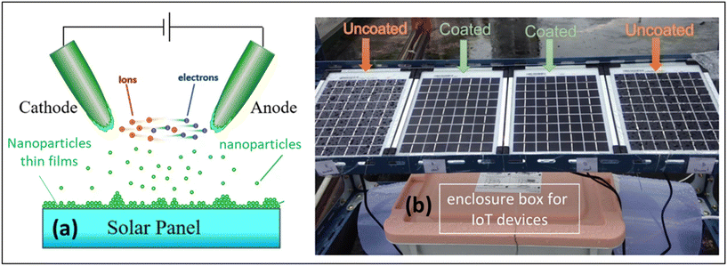 | ||
| Fig. 12 (a) Schematic diagram of the coating mechanism of nanoparticle films prepared by the sparking process and (b) image of the uncoated and coated solar panels after rain. Reproduced with permission;82 Copyright 2022, Nature. | ||
The photocatalytic hydrophilic surfaces tend to decompose dust and other impurities present on the surface under sunlight or indoor light. TiO2-based photocatalysts have been especially found to possess high physical and chemical stability, low toxicity and outstanding photoactivity.79 The cleaning process mainly relies on the reaction of TiO2 with ultraviolet light to split organic dirt.81 Various materials along with TiO2 like SiO2, TEOS or a combination of these are used to achieve superhydrophilic properties.
Factors affecting superhydrophobic surface self-cleaning performance
Pinning effects
The self-cleaning performance of superhydrophobic surfaces is largely influenced by the ease with which water droplets can move across the surface. The surface roughness of superhydrophobic coatings, as described by the Wenzel and Cassie–Baxter models, can cause either sticky or slippery behaviour, depending on the surface's wettability (presented in Fig. 13a). In contrast to the slippery surface, the water droplets on a sticky surface may remain stationary even when the surface is turned upside down. This phenomenon, known as the pinning effect, plays a crucial role in the effectiveness of self-cleaning solar panel coatings.83,84 The movement of water droplets from lower to higher wettability surfaces vs. time is depicted in Fig. 13b. Solid fraction and the triple-phase contact line (TCL) are the common concepts for the determination of the pinning effect.83,84 The pinning effect of the advancing droplet is characterized by a new constraint, which is termed the local triple-phase contact line (LTCL).85 In this theory, once the droplet volume is increased to a certain value, the advancing boundary of the water droplet will de-pin from one row of pillars and quickly slip.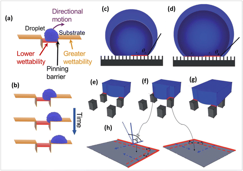 | ||
| Fig. 13 (a) Schematic illustration of the pinning phenomenon, (b) movement of water droplets from lower to higher wettability with time (c), pinning mode transits to a (d) depinning mode during the volume growing water droplet on a patterned superhydrophobic surface in the Cassie state. The evolution of the local triple-phase contact line (LTCL) with increasing droplet volume on a micropillar superhydrophobic surface, from (e) the initial contacting stage increasing droplet volume on a micropillar superhydrophobic surface, (f) the pinning stage to (g) the depinning stage, and (h) the sketch of the evolutionary process of local contact angles.83,85 | ||
This pinning–depinning process was repeatedly observed on every sample, as sketched in Fig. 13. The existence of the droplet pinning phenomenon indicated that there existed a pinning force on the liquid/solid interface, which explains the existence of many metastable droplets with different apparent contact angles on the same superhydrophobic sample. During the entire process, as the apparent contact angle increases, the driving force by surface tension opposing the pinning force per unit length of the apparent droplet boundary also increases. Once the apparent contact angle reaches the largest value (the advancing contact angle), the driving force overcomes the pinning force causing the droplet to move.
Wu et al. observed that patterned hydrophobic surfaces, which have a lower solid fraction, can exhibit stronger pinning effects than flat hydrophobic surfaces.85 This suggests that the pinning effect cannot be predicted solely by the liquid/solid contact area fraction.
There are two interfaces present in Cassie droplets: the liquid/solid interface and the liquid/air interface at the base. Fluid has a high degree of mobility on the interface between liquid and air. Thus, it may be inferred that the pinning force arises from the interface between the liquid and the solid. Fig. 13 illustrates the process of pinning and depinning. Once the volume of the droplet reaches a specific threshold, the leading edge of the water droplet will detach from one row of pillars and rapidly move across the “air gap” between the pillars to the next row. During the initial contact phase, the LTCL is confined to only one side of the pillar because of the hydrophobic properties of the surface, as shown in red in Fig. 13. As the volume of the droplet increases, the LTCL segments, which are not continuous, are unable to immediately move across the surfaces of the pillars due to the pinning force created by the edges of the pillars. This pinning force is primarily caused by the intrinsic hysteresis of the hydrophobic surface. Simultaneously, the boundary at the liquid/air interface moves unhindered towards the gap between pillars and acquires a fresh liquid/air interface below. At this stage, the length of LTCL is increased through elongation along the outer edge of the pillars, resulting in a greater pinning force on each surface of the pillars. The local pinning force continues to develop until the distance between the two neighbouring pillars is filled by the liquid/air contact, as shown in Fig. 13. The presence of this local pinning effect causes the local contact angle at the LTCL to increase, resulting in an increase in the local driving force due to surface tension with the increase in droplet volume. When the LTCL length reaches its maximum value and the contact angle advances to the local inherent advancing contact angle value, the maximum local driving force will induce the depinning motion on each surface of the pillar. This causes the droplet border to expand outward and then slide over the “air gap” before coming into contact with the next row of pillars, as seen in Fig. 13. In summary, the natural hysteresis on a hydrophobic surface prevents the LTCL segments from aggressively expanding during the initial stage of volume increase. Once the local contact angle on the hydrophobic surface reaches the inherent advancing contact angle value and the LTCL length is extended to a specific value, the driving force on each pillar will surpass the pinning force, resulting in the depinning motion. In order to achieve this objective, precise control over the movement of droplets can be accomplished by the implementation of a well-designed substrate.
Anti-fogging and anti-icing coatings
Fogging poses a significant challenge for solar panel installations, particularly in cold regions or during winter. Many solutions have been proposed to mitigate fogging, such as electrothermal devices that prevent fogging and frosting on the glass surface. However, these devices require external electricity. Coatings offer a more practical and effective approach for combating fogging, especially in environments where fog forms due to cold temperatures and hot vapor.41Shibraen et al. have developed quarternized cellulose (QC)/carboxymethyl cellulose (CMC) thin films on glass substrates through a layer-by-layer assembly process.86 The coated glass remained fog-free after exposure to a high humidity environment (37 °C, RH 85%) for 4 h followed by cooling at −20 °C. Shang and Zhou have prepared a porous silica-based superhydrophobic coating on glass substrates, which can effectively prevent water condensation when exposed to a boiling bath for 5 min.87 The tiny fog droplets on the coated glass disappeared completely within 10 seconds, while droplets on bare glass remained for over 2 minutes. Sun et al. also reported excellent anti-fogging performance in a similar study, where their coating showed superior results in an artificial fogging chamber after just 2 minutes.88 A bioinspired nano-ZnO, known as a fly-eye inspired superhydrophobic coating, showed that fog rolled off the coated surface at a tilt angle of 10°, whereas fog droplets remained strongly adhered to bare glass even at the same angle.88 Cleaning can damage solar cell surfaces, highlighting the need for anti-snow and anti-ice materials as a solution.89,90 Below freezing temperatures, two mechanisms help mitigate icing: the partial or complete rebound of droplets upon impact and the shedding of sessile droplets by external forces. In the first mechanism, droplets detach from superhydrophobic surfaces prior to freezing. However, on hydrophilic surfaces, droplets spread and remain, eventually freezing. In the second mechanism, shedding droplets from hydrophilic surfaces requires more external force, allowing enough time for freezing to occur. In contrast, superhydrophobic surfaces require less force to shed droplets, preventing or delaying ice formation by allowing water to be removed before it can freeze. On a hydrophilic surface, a droplet may stay attached or move slowly under external forces, increasing the likelihood of freezing.41
Interest in low ice-adhesion coatings has been renewed and Zuo et al. developed an anti-frost coating using nano-ZnO.91 The results show that the glass coated with superhydrophobic coating remained frost-free for 40 min compared to bare glass, which froze after 24 minutes at −5 °C. The coated surface remained frost-free for 153 minutes at −5 °C and 140 minutes at −10 °C. Guo et al. reported that nanosilica and nano-CaCO3, with a water contact angle (WCA) of approximately 166.4°, prevented ice formation for 60 minutes during glaze icing.92 Only 20% of the coated glass was covered with ice, while bare glass was fully covered with a thick layer of ice. The small sliding angle of 0.9° allowed water droplets to slide off the coated surfaces quickly, reducing ice formation.
Multi-functional solar panel coatings
Multi-functional surface coatings for solar panel applications, also known as “smart” coatings, are always preferred. These can be transparent, anti-reflective, superhydrophobic, self-cleaning, anti-fogging, self-healing, etc. Faustini et al. developed a multi-functional sol–gel nanostructured coating for solar panels having properties such as hydrophobic, self-cleaning, antireflective and anti-fogging. This multi-functional coating was attained by sol–gel liquid deposition of two successive oxide layers. The first coating consists of a hybrid methyl-functionalized nanoporous SiO2. The second layer is an ultrathin crystalline TiO2 nanoperforated layer that was deposited on top of the previous antireflective layer.20 Though various coatings are embedded with self-healing, it is crucial to maintain high transparency, desired wettability and good environmental stability for designing solar panel coatings.Liu et al. have described the fabrication of a transparent self-healing superhydrophobic coating by introducing perfluorooctyl acid (PFA) in porous silica nanotubular coating.93 The PFA-filled nanotubular coating is transparent with a transmittance of 87% and a WCA of 160–170° and is able to repeatedly heal the plasma-damaged superhydrophobicity at 70 °C. Li et al. have developed transparent superhydrophobic coatings, exhibiting spontaneous room temperature self-healing via spray coating an ethanol solution of polydimethylsiloxane (PDMS)-based supramolecular polymer cross-linked via N-coordinated boroxines (N-boroxine-PDMS) and SiO2 nanoparticles as depicted in Fig. 14.94 The polymeric coatings possess good transparency with a transmittance at 550 nm of 90% and excellent superhydrophobicity with a contact angle of 161° and a sliding angle of 1°. Tan et al. reported an eco-friendly two-step technique: dipping a glass substrate into the polydimethylsiloxane/SiO2 suspension followed by calcination.95 The prepared coating displayed superhydrophobicity with a WCA of 164° and a sliding angle of less than 1.0° with a transmittance of ∼91.4%. Xue et al. developed a robust, self-healing superhydrophobic poly(ethylene terephthalate) (PET) fabric with a WCA of 156°, which was fabricated by a convenient solution-dipping process using a readily accessible material system comprising polydimethylsiloxane and octadecyl amine (ODA). The surface roughness was achieved by self-roughening of the ODA coating on PET fibres without any lithography steps or adding any nanomaterials. The following coating was durable enough to withstand 120 cycles of laundry and 5000 cycles of abrasion without significant changes in the superhydrophobicity.96
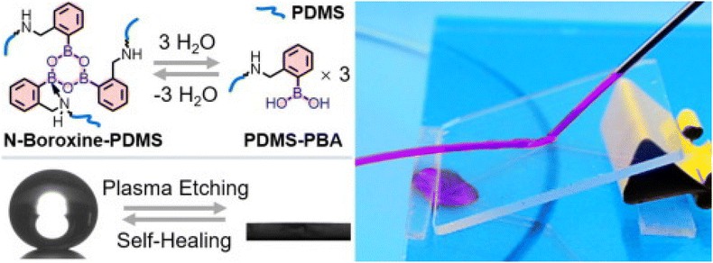 | ||
| Fig. 14 Schematic of the formation of N-boroxine-PDMS from PDMS-PBA and images of an N-boroxine-PDMS transparent film. Reproduced with permission;94 Copyright 2021, Elsevier. | ||
Transparent hydrophobic self-stratifying coatings
The current trend in coating technology is centered around self-stratifying coatings, distinguished by their ability to be applied in a single coat, in contrast to conventional coatings that typically involve multiple layers.98,99 These self-stratifying coatings exhibit multifunctional properties within a single coating system. Transparent self-stratifying coatings with hydrophobic characteristics and superior mechanical properties are of particular interest for the application of solar panel coatings. In a study conducted by the Sharma and Mandal group, a novel approach towards self-stratifying coatings was presented, utilizing copolymers based on fluorous/thiol/siloxane.97 The combination of a silyl copolymer (PMEA-co-PCMA-co-PTEPA) and a fluorous copolymer (PMEA-co-PCMA-co-PHFA) resulted in a coating that spontaneously stratified into three layers, exhibiting a gradient behaviour (Fig. 15a). This resultant coating demonstrated a high transmittance of up to 90%, hydrophobic behaviour with a WCA of 106° and excellent hardness (28 MPa).97 Notably, the coated polymer exhibited self-healing capabilities, with >80% efficiency under UV light. The self-stratifying properties were confirmed from SEM images of a cross-section of the cured film and corresponding energy-dispersive X-ray (EDX) dot mapping of three positions (Fig. 15c and d).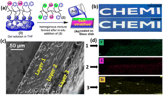 | ||
| Fig. 15 (a) Graphical representation of the formation of self-stratified polymers based on fluorous/thiol/siloxane, (b) comparison of uncoated and coated polymers on glass, (c) SEM images of a cross-section of the cured film, and (d) corresponding EDX dot mapping of three positions. Reproduced with permission;97 Copyright 2023, ACS. | ||
Furthermore, the extension of self-stratified coatings using a tannic acid, polyvinyl alcohol (PVA) and organosilane network was also explored by the same research group.100 The resulting self-stratifying coatings exhibited self-healing ability along with a WCA of 108°, excellent hardness (1 GPa), adhesion strength (12 MPa), and anti-icing performance. The self-healable coating with a transparent and hydrophobic nature holds promise for the development of next-generation solar panel coating.
Commercially available solar panel coatings
The conversion capacity of solar panels is drastically reduced by dust, grime, pollen, and other particles accumulated on the surface of solar panels with the passage of time. To resolve this issue, various commercial grade solar panel coatings have been developed which possess high-quality hydrophobic, self-cleaning, long-lasting, high-performance nanocoatings for all forms of solar photovoltaic panels. Hydrasol® is an example of such commercially available invisible superhydrophobic nanocoating for solar panels, offering self-cleaning, excellent water repellence, dirt and debris repellence and even good scratch and abrasion resistance.101 Hydrasol® also allows room temperature curing. Sinovoltaics offers a DIY® nanocoating for the solar panels which show good hydrophobicity, as illustrated in Fig. 16.102 This nanocoating provides self-cleaning activity along with resistance to salty air. Sun Density Industries has developed a sputtered nano-optical coating for the glass surface of solar panels that boosts energy harvesting by 20%, attained by capturing more blue light than standard cells. Diamon-Fusion® protective coating for solar panels provides an ultra-thin, invisible barrier that helps keep solar panels cleaner and longer along with improving photovoltaic performance and increasing energy output of solar panels.103 A rise in temperature is also a major issue for solar panels. In this context, India's TriNANO Technologies has developed a nanocoating for solar modules that lowers the temperature by up to 3 °C compared to non-coated panels.104 This nanocoating also increases the power output by up to 4% owing to its additional light trapping, anti-reflection and self-cleaning properties.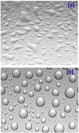 | ||
| Fig. 16 Surface properties (a) without nanocoating and (b) with nanocoating. Reproduced with permission;102 taken from the website. | ||
Conclusion and outlook
The relevance of high-performance multi-functional coatings for solar panels lies in their ability to address key challenges that affect the efficiency and longevity of photovoltaic systems. Solar panels are constantly exposed to environmental factors such as dust, moisture, UV radiation, and temperature fluctuations, all of which can degrade performance over time. Multi-functional coatings, endowed with properties like self-cleaning, anti-reflection, anti-fogging, self-healing, and self-stratifying, are essential for mitigating these impacts and enhancing overall energy conversion efficiency.In this comprehensive review, we have explored the rapid advancements and critical challenges in the development of high-performance multi-functional coatings for solar panels. The self-cleaning coating is of particular interest for solar panels as it can help in drastic improvement in solar cell efficiency, and hence many such formulations have already been commercialized. The wide range of materials that are explored in the literature for improving the self-cleaning of solar panels includes polymers, silica nanoparticles, metal oxides, fluorous-based molecules, etc.
Despite the remarkable progress, challenges such as scalability, long-term environmental stability, and integrating self-healing properties into commercially viable products still require further research. Balancing coating transparency with functionality is crucial for maintaining high light transmittance while enhancing protective properties. The commercialization of advanced coatings is still in its early stages, necessitating further research to optimize material compositions, improve scalability, and reduce production costs. Future research should focus on developing more robust and environmentally friendly coatings, exploring novel materials such as nanocomposites, and enhancing the self-healing capabilities of these coatings.
Author contributions
AKP: conceptualization, methodology, formal analysis, writing – review & editing, and validation. VS: conceptualization, visualization, writing – review & editing, and supervision, SR: conceptualization, visualization, writing – review & editing, and supervision, RKV: conceptualization, visualization, writing – review & editing, and supervision.Abbreviations
| ARC | Anti-reflective coatings |
| WCA | Water contact angle |
| PDMS | Polydimethylsiloxane |
| PV | Photovoltaic |
| TiO2 | Titanium oxide |
| ZnO | Zinc oxide |
| SiO2 | Silicon dioxide |
| SnO2 | Tin oxide |
| Al2O3 | Aluminium oxide |
| Bi2O3 | Bismuth oxide |
| TEOS | Tetraethyl orthosilicate |
| TMOS | Tetraethyl orthosilicate |
| VTES | Vinyl triethoxy silane |
| DMF | Dimethylformamide |
| HMDS | Hexamethyldisilazane |
| PFA | Perfluorooctyl acid |
| ODA | Octadecylamine |
| PET | Poly(ethylene terephthalate) |
| PTFE | Polytetrafluoroethylene |
| PVDF | Polyvinylidene fluoride |
| ZnS | Zinc sulfide |
| PVC | Polyvinyl chloride |
| PU | Polyurethane |
| PEDOT:PSS | Poly(3,4-ethylenedioxythiophene) polystyrene sulfonate |
| PUA | Polyurethane acrylate |
| TEA | 3-(Triethoxysilyl)propyl acrylate |
| CMA | Cinnamyl methacrylate |
| MEA | 2-Mercaptoethylacrylate |
| HEA | Heptafluorobutylacrylate |
| PFPE | Perfluoropolyether |
| LBL | Layer-by-layer |
| PAH | Poly(allylamine hydrochloride) |
| PAA | Poly(acrylic acid) |
| Pluronic F127 | A triblock copolymer consisting of a central hydrophobic block of polypropylene glycol with two hydrophilic blocks of polyethylene glycol |
| NOA63 | Norland Optical Adhesive 63 |
Data availability
The authors declare that the data supporting the findings of this report are available within the paper. Should any raw data files be needed in another format, they are available from the corresponding author upon reasonable request.Conflicts of interest
The authors declare that they have no known competing financial interests or personal relationships that could have appeared to influence this review paper.Acknowledgements
The authors wish to acknowledge the management of the BPCL R&D Centre for providing the necessary facilities to carry out the work and granting permission to publish this review paper.References
- A. S. Sarkın, N. Ekren and S. Saglam, Sol. Energy, 2020, 199, 63–73 CrossRef
.
- A. Jaswal and M. K. Sinha, Adv. Manuf. Ind. Eng., 2021, 835–844 Search PubMed
.
- K. Y. Patil, V. P. Sonawane and Y. G. Patil, Int. J. Innovative Res. Sci. Eng., 2016, 2, 607 Search PubMed
.
- . Solar Cell Material Top Rated Theoretical Efficiencies as of 2015, University Wafer, USA, https://www.universitywafer.com/Wafers_Services/Solar_Wafers/solar_wafers.html (accessed 22.09.2024).
- M. R. Maghami, H. Hizam, C. Gomes, M. A. Radzi, M. I. Rezadad and S. Hajighorbani, Renewable Sustainable Energy Rev., 2016, 59, 1307–1316 CrossRef
.
- A. A. Hegazy, Renewable Energy, 2001, 22, 525–540 CrossRef CAS
.
-
S. Sahoo, S. Pradhan and S. Das, in Superhydrophobic Polymer Coatings, Elsevier, 2019, pp. 281–297 Search PubMed
.
- Z. Liang, Z. Zhou, L. Zhao, B. Dong and S. Wang, New J. Chem., 2020, 44, 14481–14489 RSC
.
- A. Mishra, V. Rathi and G. Era, Int. J. Eng. Res. Elect. Electron. Eng., 2017, 3, 2395–2717 Search PubMed
.
- S. S. Latthe, R. S. Sutar, V. S. Kodag, A. K. Bhosale, A. M. Kumar, K. Kumar Sadasivuni, R. Xing and S. Liu, Prog. Org. Coat., 2019, 128, 52–58 CrossRef CAS
.
- D. Adak, R. Bhattacharyya and H. C. Barshilia, Renewable Sustainable Energy Rev., 2022, 159, 112145 CrossRef
.
- H. J. Ensikat, P. Ditsche-Kuru, C. Neinhuis and W. Barthlott, Beilstein J. Nanotechnol., 2011, 2, 152–161 CrossRef CAS PubMed
.
- Y. T. Cheng and D. E. Rodak, Appl. Phys. Lett., 2005, 86, 144101 CrossRef
.
- M. A. Samaha, H. V. Tafreshi and M. Gad-el-Hak, C. R. Mec., 2012, 340, 18–34 CrossRef
.
- M. S. Mozumder, A.-H. I. Mourad, H. Pervez and R. Surkatti, Sol. Energy Mater. Sol. Cells, 2019, 189, 75–102 CrossRef CAS
.
- S. Jalaly, M. Vahdani, M. Shahabadi and G. M. M. Sadeghi, Sol. Energy Mater. Sol. Cells, 2019, 189, 175–180 CrossRef CAS
.
- H. K. Raut, V. A. Ganesh, A. S. Nair and S. Ramakrishna, Energy Environ. Sci., 2011, 4, 3779–3804 RSC
.
-
S. B. Ulaeto, J. K. Pancrecious, T. P. D. Rajan and B. C. Pai, in Noble Metal-Metal Oxide Hybrid Nanoparticles, ed. S. Mohapatra, T. A. Nguyen and P. Nguyen-Tri, Woodhead Publishing, 2019, pp. 341–372, DOI:10.1016/B978-0-12-814134-2.00017-6
.
-
A. Mishra, N. Bhatt and A. Bajpai, in Nanomaterials-Based Coatings, Elsevier, 2019, pp. 397–424 Search PubMed
.
- M. Faustini, L. Nicole, C. Boissiere, P. Innocenzi, C. Sanchez and D. Grosso, Chem. Mater., 2010, 22, 4406–4413 CrossRef CAS
.
- X. Lu, Z. Wang, X. Yang, X. Xu, L. Zhang, N. Zhao and J. Xu, Surf. Coat. Technol., 2011, 206, 1490–1494 CrossRef CAS
.
-
A. K. Padhan and D. Mandal, in Self-Healing Polymer-Based Systems, ed. S. Thomas and A. Surendran, Elsevier, 2020, pp. 17–73, DOI:10.1016/B978-0-12-818450-9.00002-7
.
- R. P. Wool, Soft Matter, 2008, 4, 400–418 RSC
.
- S. Wang and M. W. Urban, Nat. Rev. Mater., 2020, 5, 562–583 CrossRef CAS
.
- A. K. Padhan and D. Mandal, Polym. Chem., 2018, 9, 3248–3261 RSC
.
- D. Bekas, K. Tsirka, D. Baltzis and A. S. Paipetis, Composites, Part B, 2016, 87, 92–119 CrossRef CAS
.
- Y. Yang and M. W. Urban, Chem. Soc. Rev., 2013, 42, 7446–7467 RSC
.
- https://www.optimoda.es/lente-oftalmica/shamirpresenta-un-nuevo-tratamiento-anti-vaho/ , (accessed on 22.09.2024).
- https://www.kit.edu/kit/english/pi_2021_029_anti-reflective-films-what-high-tech-can-learn-from-plants.php (accessed on 22.09.2024).
- J. Cai and L. Qi, Mater. Horiz., 2015, 2, 37–53 RSC
.
- S. Chattopadhyay, Y.-F. Huang, Y.-J. Jen, A. Ganguly, K. Chen and L. Chen, Mater. Sci. Eng., R, 2010, 69, 1–35 CrossRef
.
- A. Jalali, M. R. Vaezi, N. Naderi, F. Taj Abadi and A. Eftekhari, Chem. Pap., 2020, 74, 253–260 CrossRef CAS
.
- Y. Lee, D. Gong, N. Balaji, Y.-J. Lee and J. Yi, Nanoscal Res. Lett., 2012, 7, 50 CrossRef PubMed
.
- D. Gong, Y. J. Lee, M. Ju, J. Ko, D. Yang, Y. Lee, G. Choi, S. Kim, J. Yoo and B. Choi, Jpn. J. Appl. Phys., 2011, 50, 08KE01 CrossRef
.
- M. Beye, M. Faye, A. Ndiaye, F. Ndiaye and A. S. Maiga, Res. J. Appl. Sci., Eng. Technol., 2013, 6, 412–416 CrossRef CAS
.
-
D. I. Paul, The Effects of Dust and Heat on Photovoltaic Modules: Impacts Sol, 2022, pp. 3–46 Search PubMed
.
- H. Almukhtar, T. T. Lie, W. A. Al-Shohani, T. Anderson and Z. Al-Tameemi, Energies, 2023, 16, 3401 CrossRef CAS
.
- Y. Y. Quan and L.-Z. Zhang, Sol. Energy Mater. Sol. Cells, 2017, 160, 382–389 CrossRef CAS
.
- V. Zorba, E. Stratakis, M. Barberoglou, E. Spanakis, P. Tzanetakis, S. H. Anastasiadis and C. Fotakis, Adv. Mater., 2008, 20, 4049–4054 CrossRef CAS
.
- J. Wang, H. Chen, T. Sui, A. Li and D. Chen, Plant Sci., 2009, 176, 687–695 CrossRef CAS
.
- A. Syafiq, A. Pandey, N. Adzman and N. Abd Rahim, Sol. Energy, 2018, 162, 597–619 CrossRef
.
- L. Feng, S. Li, Y. Li, H. Li, L. Zhang, J. Zhai, Y. Song, B. Liu, L. Jiang and D. Zhu, Adv. Mater., 2002, 14, 1857–1860 CrossRef CAS
.
- J. T. Hirvi and T. A. Pakkanen, Langmuir, 2007, 23, 7724–7729 CrossRef CAS PubMed
.
- A. Syafiq, V. Balakrishnan, M. S. Ali, S. J. Dhoble, N. A. Rahim, A. Omar and A. H. A. Bakar, Curr. Opin. Chem. Eng., 2022, 36, 100801 CrossRef
.
- K. Ko, D. Yoon, S. C. Yang and H. S. Lee, J. Ind. Eng. Chem., 2022, 106, 460–468 CrossRef CAS
.
- Y. Rahmawan, L. Xu and S. Yang, J. Mater. Chem. A, 2013, 1, 2955–2969 RSC
.
- Y. Wang, J. Liu and L. Nie, ChemistrySelect, 2020, 5, 10220–10227 CrossRef CAS
.
- Z. Ji, Y. Liu and F. Du, Prog. Org. Coat., 2021, 157, 106294 CrossRef CAS
.
- S.-D. Wang and Y.-Y. Shu, J. Coat. Technol. Res., 2013, 10, 527–535 CrossRef CAS
.
- R. Prado, G. Beobide, A. Marcaide, J. Goikoetxea and A. Aranzabe, Sol. Energy Mater. Sol. Cells, 2010, 94, 1081–1088 CrossRef CAS
.
- C. Ke, Z. Li, C. Zhang, X. Wu, Z. Zhu and Y. Jiang, Coatings, 2021, 11, 174 CrossRef CAS
.
- J. Zhao, S. Chen, W. Su, L. Zhu, X. Cheng, J. Wu, S. Zhao and C. Zhou, Thin Solid Films, 2021, 717, 138467 CrossRef CAS
.
- M. Zhong, Y. Zhang, X. Li and X. Wu, Surf. Coat. Technol., 2018, 347, 191–198 CrossRef CAS
.
- A. R. Siddiqui, W. Li, F. Wang, J. Ou and A. Amirfazli, Appl. Surf. Sci., 2021, 542, 148534 CrossRef CAS
.
- B. Ameduri, Chem. – Eur. J., 2018, 24, 18830–18841 CrossRef CAS PubMed
.
- B. Ameduri, Macromol. Chem. Phys., 2020, 221, 1900573 CrossRef CAS
.
- S. N. Chavan, A. K. Padhan and D. Mandal, Polym. Chem., 2018, 9, 2258–2270 RSC
.
- T. X. Lin, K. J. Chen, P. Y. Chen and J. S. Jan, ACS Appl. Nano Mater., 2018, 1, 741–750 CrossRef CAS
.
- L. Xu, R. G. Karunakaran, J. Guo and S. Yang, ACS Appl. Mater. Interfaces, 2012, 4, 1118–1125 CrossRef CAS PubMed
.
- H. Lei, J. Xiao, L. Zheng, M. Xiong, Y. Zhu, J. Qian, Q. Zhuang and Z. Han, Polymer, 2016, 86, 22–31 CrossRef CAS
.
- J. Peng, X. Zhao, W. Wang and X. Gong, Langmuir, 2019, 35, 8404–8412 CAS
.
- K. Tadanaga, J. Morinaga, A. Matsuda and T. Minami, Chem. Mater., 2000, 12, 590–592 CrossRef CAS
.
- A. Nakajima, K. Hashimoto, T. Watanabe, K. Takai, G. Yamauchi and A. Fujishima, Langmuir, 2000, 16, 7044–7047 CrossRef CAS
.
- X. Lu, C. Zhang and Y. Han, Macromol. Rapid Commun., 2004, 25, 1606–1610 CrossRef CAS
.
- X. Li, G. Chen, Y. Ma, L. Feng, H. Zhao, L. Jiang and F. Wang, Polymer, 2006, 47, 506–509 CrossRef CAS
.
- S. J. Choi and S. Y. Huh, Macromol. Rapid Commun., 2010, 31, 539–544 CrossRef CAS PubMed
.
- W. S. Y. Wong, Z. H. Stachurski, D. R. Nisbet and A. Tricoli, ACS Appl. Mater. Interfaces, 2016, 8, 13615–13623 CrossRef CAS PubMed
.
- G. Li, B. Wang, Y. Liu, T. Tan, X. Song and H. Yan, Appl. Surf. Sci., 2008, 255, 3112–3116 CrossRef CAS
.
- N. L. Tarwal and P. S. Patil, Appl. Surf. Sci., 2010, 256, 7451–7456 CrossRef CAS
.
- J. Xiong, S. N. Das, B. Shin, J. P. Kar, J. H. Choi and J.-M. Myoung, J. Colloid Interface Sci., 2010, 350, 344–347 CrossRef CAS PubMed
.
- Y. Li, M. Zheng, L. Ma, M. Zhong and W. Shen, Inorg. Chem., 2008, 47, 3140–3143 CrossRef CAS PubMed
.
- P. Hiralal, C. Chien, N. N. Lal, W. Abeygunasekara, A. Kumar, H. Butt, H. Zhou, H. E. Unalan, J. J. Baumberg and G. A. J. Amaratunga, Nanoscale, 2014, 6, 14555–14562 RSC
.
- W. Zhao and H. Lu, Coatings, 2021, 11, 1059 CrossRef CAS
.
- V. Rico, P. Romero, J. L. Hueso, J. P. Espinós and A. R. Gonzalez-Elipe, Catal. Today, 2009, 143, 347–354 CrossRef CAS
.
- E. Hosono, H. Matsuda, I. Honma, M. Ichihara and H. Zhou, Langmuir, 2007, 23, 7447–7450 CrossRef CAS PubMed
.
- X. Liu and J. He, Langmuir, 2009, 25, 11822–11826 CrossRef CAS PubMed
.
- L. Li, G. Zhang and Z. Su, Angew. Chem., Int. Ed., 2016, 55, 9093–9096 CrossRef CAS PubMed
.
- Z. Bai, Y. Hu, S. Yan, W. Shan and C. Wei, RSC Adv., 2017, 7, 1966–1974 RSC
.
- C. Fan, C. Chen, J. Wang, X. Fu, Z. Ren, G. Qian and Z. Wang, J. Mater. Chem. A, 2014, 2, 16242–16249 RSC
.
- D. A. Keane, K. G. McGuigan, P. F. Ibanez, M. I. Polo-Lopez, J. A. Byrne, P. S. M. Dunlop, K. O'Shea, D. D. Dionysiou and S. C. Pillai, Catal. Sci. Technol., 2014, 4, 1211–1226 RSC
.
- E. González, A. Bonnefond, M. Barrado, A. M. Casado Barrasa, J. M. Asua and J. R. Leiza, Chem. Eng. J., 2015, 281, 209–217 CrossRef
.
- W. Thongsuwan, W. Sroila, T. Kumpika, E. Kantarak and P. Singjai, Sci. Rep., 2022, 12, 1675 CrossRef CAS PubMed
.
- P. E. Theodorakis, A. Amirfazli, B. Hu and Z. Che, Langmuir, 2021, 37, 4248–4255 CrossRef CAS PubMed
.
- W. P. Huang, X. Chen, M. Hu, D. F. Hu, J. Wang, H. Y. Li, K. F. Ren and J. Ji, Chem. Mater., 2019, 31, 834–841 CrossRef CAS
.
- J. Wu, J. Xia, W. Lei and B.-p. Wang, RSC Adv., 2014, 4, 35649–35652 RSC
.
- M. H. M. A. Shibraen, H. Yagoub, X. Zhang, J. Xu and S. Yang, Appl. Surf. Sci., 2016, 370, 1–5 CrossRef CAS
.
- Q. Shang and Y. Zhou, Ceram. Int., 2016, 42, 8706–8712 CrossRef CAS
.
- Z. Sun, T. Liao, K. Liu, L. Jiang, J. H. Kim and S. X. Dou, Small, 2014, 10, 3001–3006 CrossRef CAS PubMed
.
- B. P. Jelle, T. Gao, S. A. Mofid, T. Kolas, P. M. Stenstad and S. Ng, Procedia Eng., 2016, 145, 699–706 CrossRef
.
- P. Kim, T.-S. Wong, J. Alvarenga, M. J. Kreder, W. E. Adorno-Martinez and J. Aizenberg, ACS Nano, 2012, 6, 6569–6577 CrossRef CAS PubMed
.
- Z. Zuo, R. Liao, X. Zhao, X. Song, Z. Qiao, C. Guo, A. Zhuang and Y. Yuan, Appl. Therm. Eng., 2017, 110, 39–48 CrossRef CAS
.
- C. Guo, R. Liao, Y. Yuan, Z. Zuo and A. Zhuang, J. Nanomater., 2015, 2015, 404071 CrossRef
.
- Y. P. Liu, H. F. Liu, Y. G. Feng, Z. L. Liu, H. Y. Hu, B. Yu, F. Zhou and Q. J. Xue, RSC Adv., 2016, 6, 21362–21366 RSC
.
- X. Li, B. Li, Y. Li and J. Sun, Chem. Eng. J., 2021, 404, 126504 CrossRef CAS
.
- Y. Liu, X. Tan, X. Li, T. Xiao, L. Jiang, S. Nie, J. Song and X. Chen, Langmuir, 2022, 38, 12881–12893 CrossRef CAS PubMed
.
- C. H. Xue, X. Bai and S. T. Jia, Sci. Rep., 2016, 6, 27262 CrossRef PubMed
.
- D. Sharma and D. Mandal, ACS Appl. Polym. Mater., 2023, 5, 7051–7059 CrossRef CAS
.
- D. J. Walbridge, Prog. Org. Coat., 1996, 28, 155–159 CrossRef CAS
.
- A. Beaugendre, S. Degoutin, S. Bellayer, C. Pierlot, S. Duquesne, M. Casetta and M. Jimenez, Prog. Org. Coat., 2017, 110, 210–241 CrossRef CAS
.
- D. Sharma and D. Mandal, J. Mater. Chem. A, 2023, 11, 25683–25691 RSC
.
- https://www.antlab.in/hydrasol-solar-nano-coating.php . (Accessed 22.09.2024).
- https://sinovoltaics.com/technology/solar-panel-nano-coatings-use-or-not/ . (Accessed 22.09.2024).
- https://dfisolutions.com/surfaces-we-protect/solar-panels/ . (Accessed 22.09.2024).
- https://www.pv-magazine-india.com/2023/06/28/new-nanocoating-to-improve-solar-module-output/ . (Accessed 22.09.2024).
| This journal is © The Royal Society of Chemistry 2025 |
