
 Open Access Article
 This Open Access Article is licensed under a
 Creative Commons Attribution 3.0 Unported Licence
Magnetoelastic coupling in the stretched diamond lattice of TbTaO4†
Xiaotian
Zhang
 a,
Nicola D.
Kelly
ab,
Denis
Sheptyakov
c,
Cheng
Liu
a,
Shiyu
Deng
ad,
Siddharth S.
Saxena
*aef and
Siân E.
Dutton
*a
a,
Nicola D.
Kelly
ab,
Denis
Sheptyakov
c,
Cheng
Liu
a,
Shiyu
Deng
ad,
Siddharth S.
Saxena
*aef and
Siân E.
Dutton
*a
aCavendish Laboratory, University of Cambridge, JJ Thomson Avenue, Cambridge, CB3 0HE, UK. E-mail: sss21@cam.ac.uk; sed33@cam.ac.uk
bDepartment of Chemistry, University of Oxford, Mansfield Rd, Oxford, OX1 3TA, UK
cLaboratory for Neutron Scattering and Imaging, Paul Scherrer Institut (PSI), Forschungsstrasse 111, 5232 Villigen PSI, Switzerland
dInstitut Laue-Langevin (ILL), 71 Avenue des Martyrs, 38000 Grenoble, France
eBritish Management University, 35 Mirza Bobur Street, Tashkent, Uzbekistan
fKazakh-British Technical University, 59 Tole Bi Street, 050000 Almaty, Kazakhstan
First published on 10th March 2025
Abstract
The magnetic structure of diamond-like lattice has been studied extensively in terms of the magnetic frustration. Here we report the distortion of stretched diamond lattice of Tb3+ (4f8) in M–TbTaO4 on application of a magnetic field. We have investigated the structural and magnetic properties of M phase terbium tantalate M–TbTaO4 as a function of temperature and magnetic field using magnetometry and powder neutron diffraction. Sharp λ-shape transitions in d(χT)/dT, dM/dH and specific heat data confirm the previously reported three-dimensional (3D) antiferromagnetic ordering at TN ∼ 2.25 K. On application of a magnetic field the Néel temperature is found to decrease and variable field neutron diffraction experiments below TN at 1.6 K show an increase in both the bond and angle distortion of the stretched diamond lattice with magnetic field, indicating a potential magneto-elastic coupling effect. By combining our magnetometry, heat capacity and neutron diffraction results we generate a magnetic phase diagram for M–TbTaO4 as a function of temperature and field.
Introduction
Previous studies of magnetism in diamond-like lattices have been mainly focused on ceramic materials, including magnetic A-site spinels, NiRh2O4,1 CuRh2O42 and MAl2O43 (M = Co, Fe, Mn) as well as scheelite KRuO44 and lanthanide NaCeO25 materials. The undistorted diamond lattice, a repeating pattern of centred tetrahedra, is a bipartite lattice capable of exhibiting colinear antiferromagnetic interactions between the nearest-neighbour spins (J1) and the quantum ground state has magnetic long range Néel order (“up-down”).6 However, most reported materials tend to show strong magnetic frustration, since the nearest neighbour interaction J1 is relatively weak compared to the next-nearest neighbour interaction J2.6 This gives rise to a variety of magnetic phenomena, ranging from long-range ordered states to disordered spin liquid and spin glass states7,8 and topologic paramagnetism.9,10 The competition between J1 and J2 can also result in multiple low energy magnetic regimes and a complicated phase diagram.11When the diamond lattice is distorted by symmetry lowering a related stretched diamond lattice is generated. In 2021, Bordelon et al. used a “stretched” (distorted) diamond lattice framework to explain the J1–J2 interaction in the tetragonal spinel LiYbO2. The magnetic order of the Yb3+ ions becomes commensurate on application of a magnetic field.12 However, the reported spin spiral magnetic structure in zero field is still subject to debate.13–15 In 2022, Kelly et al. reported the magnetic lanthanide ions (Ln3+) in monoclinic fergusonite-type LnTaO4 also form a stretched diamond lattice and introduced the concepts of bond and angular distortion to quantify the distortions in the stretched diamond lattice.16
Rare-earth tantalates LnTaO4 [Ln = Y, La–Lu] have attracted increasing attention due to their wide applications, such as phosphors,17 thermal barriers,18 scintillators19 and dielectric ceramics.20 They adopt a number of different structural polymorphs depending on the synthetic conditions.20–25 The magnetic Ln3+ ions form a stretched diamond network in both the low temperature M (I2/a, monoclinic, fergusonite) and high temperature T (I41/a, tetragonal, scheelite) phases.16 Prior work on M–LnTaO4 powders mainly focused on the luminescent and thermal properties18,19,26,27 rather than magnetism. More magnetic studies have been done on the isostructural niobates, LnNbO4,28,29 potentially due to their lower synthesis temperature. In 1996, Tsunekawa et al. reported the magnetic susceptibilities of NdTaO4, HoTaO4 and ErTaO4 single crystals with negative Curie–Weiss temperatures and no magnetic transitions between 4.2 and 300 K.30 Recently, Kelly et al. reported the bulk magnetisation of polycrystalline M–LnTaO4 (Ln = Nd, Sm–Er, Y) samples. In agreement with previous work all were found to have negative Curie–Weiss temperatures and no compounds order above 2 K, except M–TbTaO4 with an antiferromagnetic transition at 2.25 K. Powder neutron diffraction (PND) was used to determine its magnetic structure, revealing that it forms a commensurate AFM structure with ![[k with combining right harpoon above (vector)]](https://www.rsc.org/images/entities/i_char_006b_20d1.gif) = 0.16
= 0.16
Here, we expand on the prior work of Kelly et al. and focus on the nuclear and magnetic structure of M–TbTaO4 at variable temperature and magnetic field using powder neutron diffraction. At 1.6 K, below TN, a slight increase in angle distortion and band distortion is observed from 0 to 6 T. We interpret this as antiferromagnetic ordering triggering a magneto-elastic coupling in M–TbTaO4. Our variable temperature and field magnetic susceptibility, and specific heat measurements allow us to track changes in the magnetism. From these measurements, the Néel temperature of M–TbTaO4 is found to be suppressed by the magnetic field and a transition to a canted antiferromagnetic state is observed on application of a magnetic field.
Experimental
Polycrystalline M–TbTaO4 was synthesised according to a solid-state ceramic reaction as has been reported elsewhere.31 Ta2O5 (Alfa Aesar, 99.993%) and Tb4O7 (Alfa Aesar, 99.9%) powders were firstly heated at 800 °C overnight to remove moisture. Then 1![[thin space (1/6-em)]](https://www.rsc.org/images/entities/char_2009.gif) :1 molar amounts of the reagents were thoroughly mixed in an agate pestle and mortar, pressed into a 7-mm pellet and placed in an alumina crucible. The pellets were heated for 72 h at 1500 °C in air with intermediate regrinding every 24 h.
:1 molar amounts of the reagents were thoroughly mixed in an agate pestle and mortar, pressed into a 7-mm pellet and placed in an alumina crucible. The pellets were heated for 72 h at 1500 °C in air with intermediate regrinding every 24 h.
Powder X-ray diffraction (PXRD) was carried out at room temperature on a Bruker D8 diffractometer (Cu Kα, λ = 1.541 Å) in the range 10 ≤ 2θ(°) ≤ 70 with a step size of 0.02°, 0.6 s per step. Rietveld refinements32 were carried out using TOPAS33 with a Chebyshev polynomial background and Thompson–Cox–Hastings pseudo-Voigt peak shape.34 VESTA35 was used for crystal structure visualization and production of figures.
Powder neutron diffraction (PND) was carried out on an 8 g sample of M–TbTaO4, prepared by combining two batches confirmed to be phase pure by PXRD. The sample was pressed into disc-shape with a diameter of 7.1 mm and enclosed within the cadmium container. Cadmium platelets were also placed between discs, ensuring they remained immobilized. PND was conducted on the high-resolution powder diffractometer for thermal neutrons (HRPT), Paul Scherrer Institut (PSI), Villigen, Switzerland,36 using an Orange cryostat (1.5 ≤ T (K) ≤ 300). Neutrons with λ = 2.4487(2) Å were obtained by using the (400) reflection on the focusing Ge monochromator at a take-off angle of 120 deg. The determination of the magnetic structure was carried out using TOPAS.33 The background was modelled with a Chebyshev polynomial, and the peak shape was modelled with a modified Thompson–Cox–Hastings pseudo-Voigt34 function with axial divergence asymmetry.
The dc magnetisation was measured on warming on a Quantum Design MPMS®3 in the temperature range 1.8 ≤ T (K) ≤ 300 under different magnetic fields ranging from 500 Oe to 70000 Oe, after cooling from 300 K in zero field (ZFC). The isothermal magnetisation was measured on the same system in the field range μ0H = 0–7 T at different temperatures.
Heat capacity of M–TbTaO4 was measured on a Quantum Design PPMS® DynaCool in the range 1.8 ≤ T (K) ≤ 30 under different magnetic fields ranging from 0 Oe to 70000 Oe. The sample was mixed with an equal mass of Ag powder to improve thermal conductivity and pressed into a 5 mm pellet before mounting on the sample stage with Apiezon N grease. Fitting of the relaxation curves was done using the two-tau model. The contribution of Ag to the total heat capacity was subtracted using scaled values from the literature.37 The TbTaO4 lattice contribution was estimated and subtracted using a Debye model with θD = 370 K,38 as is shown in Fig. S1 (ESI†).
Results
Structure
The structure of M–TbTaO4 has been previously reported to be monoclinic fergusonite, space group 15, I2/a (unconventional unit cell) or C2/c (standard unit cell).16,22 The Ta5+ ions are connected by four shorter and two longer Ta–O bonds, forming an octahedron with second order Jahn–Teller distortion. The two edges are shared by neighbouring Ta–O octahedra, and other edges are shared with Tb–O dodecahedra as shown in Fig. 1a and b. The Tb3+ ions in the fergusonite crystal form a stretched diamond lattice or distorted honeycomb-like structure (Fig. 1c) which is predicted to host the exotic magnetic ground state.16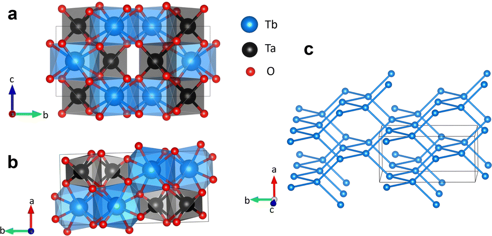 | ||
| Fig. 1 (a) and (b) Monoclinic crystal structure of M–TbTaO4 (space group I2/a). (c) The distorted diamond lattice of Tb site. The unit cell is shown in thin grey lines. | ||
Rietveld refinement of the room-temperature PXRD of M–TbTaO4, Fig. 2, indicated the formation of single monoclinic M phase in our sample after 72 hours of sintering at 1500 °C. The unit cell parameters and the Tb3+ and Ta5+ atomic positions were refined, while the atomic positions of the O2− ions were fixed based on the neutron diffraction data from previous experiment at ILL16,39 (Table S1, ESI†). The refined unit cell parameters and atomic positions, with no Tb3+/Ta5+ site disorder observed, are consistent with previous literature.18,22
 | ||
| Fig. 2 Room-temperature PXRD pattern for M–TbTaO4: red dots, experimental data; black line, calculated intensities; green line, difference pattern; blue tick marks, Bragg reflection positions. | ||
Magnetic susceptibility
The ZFC magnetic susceptibility, χ ≈ M/H, as a function of temperature is shown in Fig. 3a under selected magnetic fields. At 0.01 T, a sharp cusp feature was observed at ∼2.9 K, which agrees with the susceptibility data reported by Kelly et al.16 The cusp temperature decreases from 2.91(8) to 2.08(8) K upon increasing the field from 0.01 to 0.80 T. Above 0.80 T, the AFM ordering is gradually evolving to a FM-like ordering where χ saturates at low temperature. At high temperatures, the magnetic susceptibility is independent of field and fits the modified Curie–Weiss law: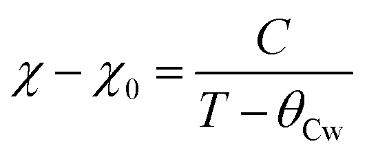
 | ||
| Fig. 3 (a) The ZFC magnetic susceptibility (Inset: At low temperatures) and (b) d(χT)/dT (χ ≈ M/H) for M–TbTaO4 as a function of temperature in selected fields. | ||
Fitting to the Curie–Weiss law was carried out using the data collected at 1 T for T > 50 K. The effective magnetic moment was calculated from the experimental data using  and compared with the theoretical moment
  . The effective moment inferred from the fit is 10.23 (1)μB per Tb is of the same order of the theoretical value 9.72μB per Tb, and the Weiss temperature is −9.67 (7) K consistent with that reported by Kelly et al.16
The derivative of the product χT with respect to temperature, d(χT)/dT as a function of temperature at selected fields are shown in Fig. 3b. At 0.01 T, a sharp lambda-type feature is observed at 2.25(1) K, which corresponds to the Néel temperature (TN1), this indicates the onset of three-dimensional AFM ordering. Additionally, another shoulder like feature is visible at ∼2.02(2) K, which we denote as TN2. This second transition suggests a more complex magnetic structure, such as multiple AFM sublattices or competing interactions. TN1 decreases from 2.25 (1) to 2.05(9) K upon increasing field from 0.01 to 0.30 T and TN2 decreases from ∼2.02(2) to 1.92(6) K as field increases from 0.01 to 0.80 T. This suggests that the AFM ordering is suppressed on application of a magnetic field.
Isothermal magnetisation
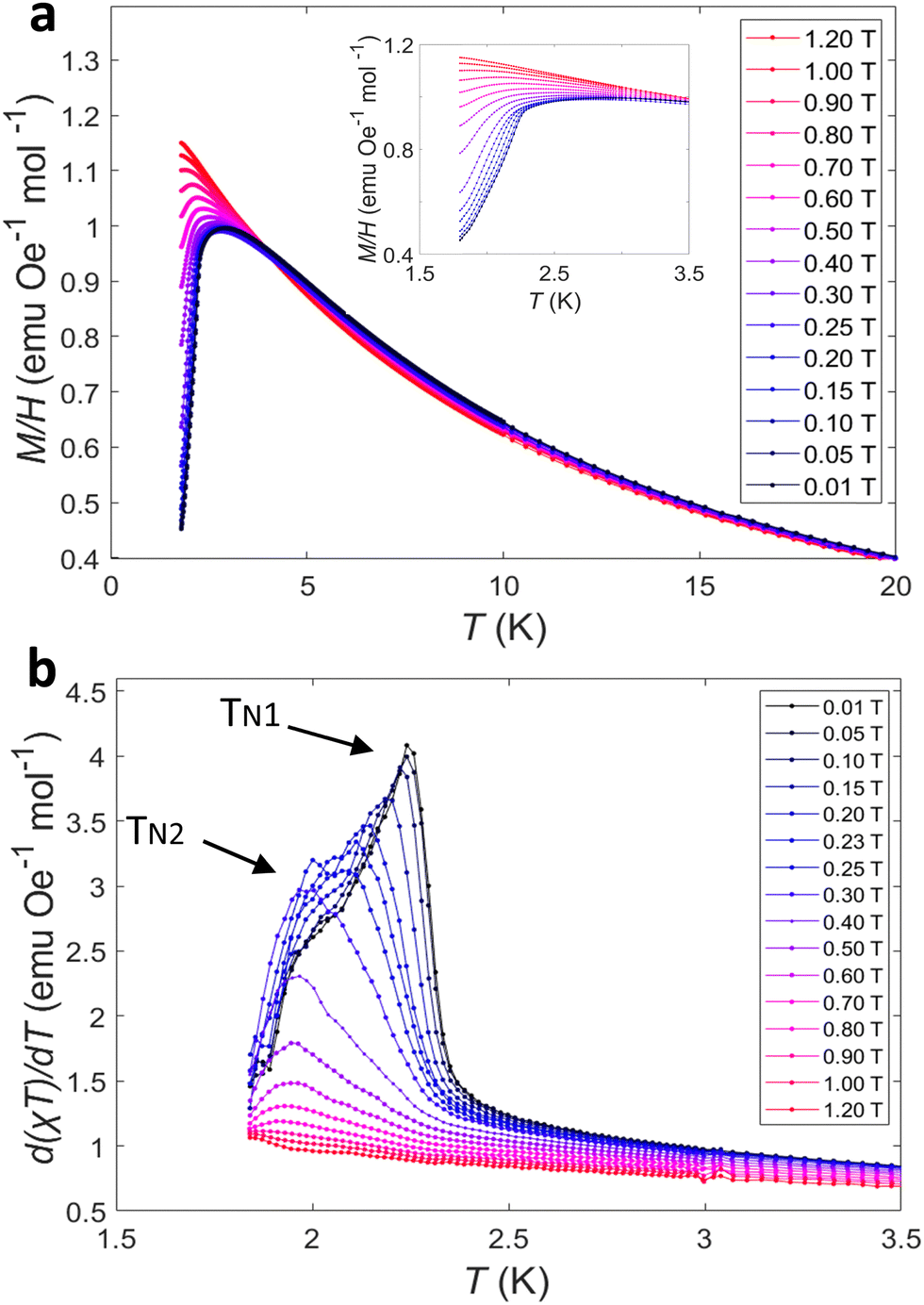
Isothermal magnetisation measurements at selected temperatures are shown in Fig. 4a. Below the higher Néel temperature (TN1), the isothermal magnetisation exhibits a characteristic ‘S’ shape curvature (Fig. 4a inset), indicative of complex interactions and spin re-orientation within the antiferromagnetic structure. As the field increases, the magnetisation reaches saturation by approximately 1.5 T. The resulting saturation magnetisation (Msat ≈ 6μB f.u.−1) is lower than the 9μB f.u.−1 expected for a Heisenberg-like Tb3+ system, reflecting spin anisotropy and powder-averaging effects. In Tb3+ compounds with Ising (easy-axis) or XY (easy-plane) behaviour, the magnetisation often saturates at gJ·J/2 or 2gJ·J/3, respectively, rather than gJ·J = 9μB f.u.−1 magnetisation expected for fully saturated Tb3+. For temperatures slightly above TN1, but below 20 K, the magnetisation curve loses the ‘S’ shape. This suggests thermal energy begins to destabilize the low field antiferromagnetic structure, make it easier for the magnetic moment to align with the field. At high temperatures (above 20 K), the magnetisation response becomes more linear with no distinct features at low fields. This linear response is a typical paramagnetic phase, where magnetic moments align more readily with external field. | ||
| Fig. 4 (a) Isothermal magnetization of M–TbTaO4 at selected temperatures from 0–7 T (Inset: From 0–1.2 T) and (b) the corresponding derivative, dM/dH as a function of field. | ||
The differential magnetisation, dM/dH, as a function of applied magnetic field is plotted in Fig. 4b at various temperatures. At temperatures below TN1, two distinct features could be observed. For data collected at 1.8 K (Fig. 4b inset), a sharp peak appeared at 0.32(2) T, which represents a field-induced spin re-orientation. This peak is likely to be a spin-flop transition in the antiferromagnetic phase. A broader peak appears at 0.76(2) T, which is also observed up to around 4 K. This broader peak suggests a gradual change, likely corresponding to a canted antiferromagnetic phase. As the temperature increases, the sharp low field peak at 0.32(2) T is gradually suppressed to 0.09(2) T at 2.25 K and not observed at higher temperatures. This indicates the thermal energy destabilizes the spin flop transition. The broader peak observed at 0.76(2) T remains visible up to 3 K and shows negligible dependence of magnetic field. This suggests it is more robust canted antiferromagnetic phase against thermal fluctuations than low-field sharp peak.
Specific heat
The magnetic specific heat of M–TbTaO4 at selected fields is shown in Fig. 5a. At the Néel temperature, a sharp peak was observed, this corresponds to the 3D AFM ordering in d(χT)/dT plot. On application of a magnetic field, the peak decreases in temperature and becomes broader. Differing from the magnetic susceptibility and isothermal magnetisation measurements, TN2 was not seen in the heat capacity data, possibly due to the change in magnetic entropy being too small to detect or insufficient temperature steps resulting in the merge of TN1 and TN2. The magnetic entropy (ΔS) change associated with the transition was obtained by integrating the Cmag/T curve from 1.8 to 20.0 K (Fig. 5b). ΔS was found to approach 4.0 J mol−1 K−1 at 0 T and decreased to ∼2.4 J mol−1 K−1 at 2 T. The Ising spins with effective spin of ½ are expected to have the maximum entropy change of R![[thin space (1/6-em)]](https://www.rsc.org/images/entities/i_char_2009.gif) ln2 = 5.76 J mol−1 K−1 at zero field. The remaining entropy change is assumed to occur below 1.8 K.
ln2 = 5.76 J mol−1 K−1 at zero field. The remaining entropy change is assumed to occur below 1.8 K.
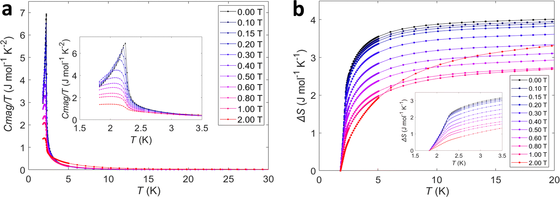 | ||
| Fig. 5 (a) Magnetic heat capacity of M–TbTaO4 as a function of temperature at selected fields and (b) magnetic entropy obtained by integration of Cmag/T. Inset: Data obtained at low temperatures. | ||
Magnetic structure
High resolution PND data for M–TbTaO4 was obtained using the HRPT/SINQ beamline at the PSI. The representative Rietveld refinement of neutron data at zero field is shown in Fig. 6a and b and in-field data are presented in Fig. S2 and S3 (ESI†). The results are consistent with the previous literature for TbTaO4.16,40 At 20 K, the application of a magnetic field results in the emergence of magnetic Bragg peaks at ∼2 T, Fig. 6c and d. The increase in intensity as the field is applied, suggesting a polarization of the Tb3+ moments in the paramagnetic phase to align with the applied field. On cooling below the Néel temperature, magnetic Bragg peaks are also observed at 0 T, Fig. 6b, however some of these are suppressed in the presence of an external magnetic field, Fig. 6d. To evaluate these changes more quantitatively, the magnetic peaks were indexed to a commensurate magnetic cell with k = 0 in the magnetic space groups P21′/c (no. 14.77) and P21′/c′(no. 14.79). The P21′/c magnetic space group is a maximal non-isomorphic subgroup of the I2/a crystallographic symmetry and arises due to the four crystallographically equivalent Tb atoms in the crystal structure being described by 2 crystallographically distinct Tb ions in the magnetically ordered structures. At 1.6 K in zero field the magnetic structure can be described by the P21′/c (14.77) magnetic space group as reported previously with the Tb spins align perpendicular to the bc plane in A-type antiferromagnetic order, as is shown in Fig. 7a. The magnetic moments align collinearly along a-axis and form ferromagnetic layers in ac plane (Fig. 7b). The ferromagnetic layers are coupled antiferromagnetically along b-axis. At zero field, the refined ordered magnetic moment is 7.8(3)μB per Tb3+. This is below the theoretical value of 9.72μB but consistent with 7.5(4)μB which has previously reported by Kelly et al.16 At higher fields of 6 T, the magnetic structure is fully described by the P21′/c′ (14.79) magnetic space groups, with the spins aligned ferromagnetically in the a direction, Fig. 7b. At intermediate fields from 0.5 to 3 T, the neutron data can be well fitted with a mixture of two magnetic space groups P21′/c and P21′/c′, corresponding to two magnetic phases: an antiferromagnetic phase and a ferromagnetic phase, respectively. Note that this approach does not represent a true phase separation but rather is the usual way to describe the spin-canting using TOPAS software. During the refinement, the phase fractions were constrained to remain identical and fixed, while the magnetic moments associated with two magnetic phases were refined independently. For the P21′/c (14.77) magnetic space group, symmetry restricts the spin to the a-axis. The net magnetic moment of the antiferromagnetic phase decreases from 5.4(2) to 0.5(1)μB as magnetic field increases from 0.5 T to 3.0 T, Fig. S6 (ESI†) In contrast, in the P21′/c′(no. 14.79) magnetic space group, spin components are allowed along all crystallographic directions. The canted ferromagnetic phase, which emerges at 0.5 T, has a net ferromagnetic component along a- and c-axes, with an antiferromagnetic component along b-axis. Both b- and c-axis components are progressively suppressed with increasing magnetic field, resulting in a dominant ferromagnetic component along a-axis at 3 T. The net moment of the canted ferromagnetic phase rises from 0.6(2) to 7.1(3)μB along a-axis as the magnetic field ranges from 0.5 to 3.0 T. | ||
| Fig. 6 (a) and (b) Refined PND data of M–TbTaO4 collected at 20.0 K and 1.6 K respectively with 0 T; (c) and (d) the corresponding heat map showing the evolution of magnetic phase with increasing magnetic field from 0 to 6 T. Red dots, experimental data; black line, calculated intensities; green line, difference pattern; tick marks, nuclear (blue), magnetic (pink) Bragg reflection positions. | ||
 | ||
| Fig. 7 (a) Magnetic structure of M–TbTaO4 from Rietveld refinement at 1.6 K, H = 0 T; (b) diagram showing the phase transition from an antiferromagnetic phase to a ferromagnetic phase in applied magnetic field; (c) the two magnetic structures of M–TbTaO4 and their evolutions with magnetic fields at 0.50 T, 0.75 T, 1.00 T and 3.00 T. Upper figure shows the antiferromagnetic structure (14.77 magnetic space group), and the lower shows the canted ferromagnetic structure (14.79 magnetic space group). Tb3+ ions are shown in blue, tantalum shown in black, and oxygen shown in red. The unit cell is shown in thin grey lines. Magnetic vectors are shown in orange (‘spin down’) and blue (‘spin up’) arrows. | ||
These findings imply the formation of a canted antiferromagnetic state from 0.5 to 3.0 T. In this state, the antiferromagnetic alignment of the Tb3+ moments begin to cant under the influence of the external magnetic field. At 0 T, the spins are aligned antiferromagnetically along the a-axis and are perpendicular to the bc plane. When a magnetic field of 0.5 T is applied, the emergence of net magnetic components along the b- and c- axes suggests that the spins start to cant towards the bc plane. As the magnetic field increases to 3 T, the b and c components are progressively suppressed, indicating that the spins are reorienting back to align predominantly along the a-axis. Eventually, at 6 T, the system transitions to ferromagnetic along the a-axis.
In addition to changes in the magnetic structure, we also observed changes in the nuclear structure of M–TbTaO4 with magnetic field. In the field range 0–6 T, no significant changes in lattice parameters were observed at 20.0 K. However, at 1.6 K, there is a subtle increase in a, b, c between 0.75 T and 6 T of ∼0.015%, as is shown in Fig. S6 (ESI†). There are also subtle changes in the refined atomic positions and bond angles on application of a field, notably the decrease of the y coordinates for Tb and O–Tb–O angles with magnetic field at 1.6 K (Fig. S7–S9, ESI†).
Discussion and phase diagram
The magnetic behaviour of M–TbTaO4 has been previously discussed with reference to the stretched diamond lattice of Tb3+ ions described by the nearest-neighbouring interactions J1 and next-nearest neighbouring interactions J2. It has been reported that the nearest-neighbouring super-exchange in M–TbTaO4 predominantly occurs through Tb–O–Tb pathways.16 These pathways can be divided into two interactions: a J1a vector in the ab plane and a J1b vector in the bc plane. These interactions depend on the interatomic nearest Tb–Tb distance d1 and d2 respectively (Fig. 8a). At 20 K, there is only small fluctuation in both d1 and d2 in magnetic field. At 1.6 K, d1 exhibits a slight increase with magnetic fields, while d2 shows an opposite tendency (Fig. 8d). | ||
| Fig. 8 (a) A single tetrahedral structure of diamond lattice, d1 and d2 are the distance between the nearest-neighbouring atoms and ϕ is the angle between bonds; (b) bond distortion db and angle distortion index da calculated from d1 and d2 and ϕ. (c) The undistorted diamond lattice and stretched diamond lattice of Tb3+ ions in M–TbTaO4; (d) and (e) d1, d2, da and db of Tb3+ as a function of magnetic field collected at 20.0 K and 1.6 K from Rietveld refinement of PND collected at λ = 2.45 Å. | ||
The extent of the stretching or distortion in the diamond-like lattice can be compared using the bond length and the angles between the bonds. In undistorted diamond lattice, all the bond lengths and bond angles are the same (Fig. 8c), and the angles are all equal to 109.5°, while in the monoclinic symmetry there are three different bond lengths and four different angles. Here, we compare the relative deviation from the ideal diamond lattice by using the bond length distortion index da and bond angle distortion db16 as is shown in Fig. 8b, where ϕmax and ϕmin are the largest and smallest angles respectively between Tb–Tb–Tb bonds, respectively. These indices allow us to systematically quantify the structural distortions as the system is subjected to external parameters such as temperature and magnetic field.
Interestingly, the angle and bond distortions exhibit a clear dependency on the applied magnetic field, indicative of an underlying magneto-elastic coupling. At 20 K, only a slight increase in da and db was observed as the magnetic field increased, but a more pronounced increase in both distortion parameters is observed as the temperature decreased, as is shown in Fig. 8e. At 1.6 K, (T < TN), the bond distortion index db increased by approximately 0.6%, and the angle distortion index da increased by approximately 1.1% as the magnetic field was varied from 0 to 6 T.
This behaviour can be directly attributed to magneto-elastic coupling, where the interaction between the magnetic moments of the Tb3+ ions and the lattice vibrations induce elastic strain in the crystal structure. In this system, the magnetic field alters the interactions and the orientation of magnetic moments, which, in turn, leads to lattice distortions as the crystal attempts to minimize its free energy. Consequently, both bond lengths and bond angles change, reflecting the strong coupling between magnetic order and lattice dynamics. This effect becomes particularly significant at low temperatures below TN where quantum effects and collective spin ordering dominate the system's behaviour due to the presence of 4f8 Tb3+ which are known to exhibit quantum behaviour.41
The transition temperatures against magnetic fields obtained from d(χT)/dT, dM/dH and Cmag/T have been summarized in the magnetic phase diagram shown in Fig. 9. From 2.25 to 2.11 K (the corresponding field ranges from 0 to 0.225 T), TN1 from d(χT)/dT, dM/dH and Cmag overlap with each other, the magnetic specific heat diverges below 2.11 K. The divergency below Néel temperature separates the phase diagram into three regimes, which we classify as AFM, canted AFM and FM phases from our PND study. AFM phase refers to the phase that the Tb spins align perpendicular to bc plane, whilst in the canted AFM phase, the Tb spins are gradually canted due to the increasing field but remain the AFM ordering, finally entering the FM phase at higher fields. Further study of the hard and easy axis will require anisotropic magnetisation measurements on single crystals.
 | ||
| Fig. 9 Proposed magnetic phase diagram for M–TbTaO4 as a function of magnetic field and temperature. Transition values derived from the magnetic specific heat, magnetic susceptibility (TN1 and TN2) and isothermal magnetization are shown as black squares, orange circles, red diamonds, and blue crosses respectively. | ||
Conclusions
We have systematically investigated the magnetic properties of polycrystalline M–TbTaO4 as a function of temperature and applied magnetic field. Three-dimensional antiferromagnetic ordering is observed at TN1 and consistent with the previous literatures. We discover, for the first time, a second Néel temperature TN2 in d(χT)/dT. We find that both Néel temperatures (TN1 and TN2) in M–TbTaO4 could be suppressed on application of a magnetic field up to 0.8 T. Overall, this suggests a detailed three-regime phase diagram in M–TbTaO4 below its transition temperature.We have also studied the evolution of magnetic structure by powder neutron diffraction measurements below and above TN, under varying magnetic fields. Below the AFM transition temperature of 2.25 K, we observed the appearance of magnetic peaks which were suppressed by magnetic field. We find that the magnetic moments of Tb3+ ions, which are initially aligned parallel to the a-axis in Néel AFM order, cant towards the bc plane on application of the external magnetic field and eventually form a FM order parallel to the a-axis again
The Tb3+ sites in M–TbTaO4 have been reported to from an elongated and stretched diamond lattice. Notably, we have observed a slight increase in both angle and bond distortion of this stretched diamond lattice from 0 to 6 T at 1.6 K. This indicates that the antiferromagnetic ordering in M–TbTaO4 could potentially be linked to a magneto-elastic coupling effect.
Future work including dielectric measurements would be highly required to unveil the potential coupling effect between magnetic order and nuclear order. The magnetic measurement on single crystal would also be essential to quantify the possible magnetic anisotropy along different axes in M–TbTaO4.
Author contributions
X. Zhang: conceptualization, data curation, formal analysis, investigation, validation, visualization, writing original draft, writing – review & editing. N. Kelly: conceptualization, data curation, formal analysis, investigation, writing – review & editing. D. Sheptyakov: data curation, investigation, resources. C. Liu: data curation, investigation, resources, writing – review & editing. S. Deng: data curation, investigation. S. Saxena: conceptualization, formal analysis, investigation, supervision, project administration, funding acquisition, resources, writing review & editing. S. Dutton: conceptualization, formal analysis, investigation, supervision, project administration, funding acquisition, resources, writing review & editing.Data availability
The datasets that support the findings of this study, including those from magnetic measurement, heat capacity measurement, Powder X-ray and Neutron diffraction, are available at https://doi.org/10.17863/CAM.113572.Conflicts of interest
There are no conflicts to declare.Acknowledgements
For this commemorative issue, SSS would like to acknowledge Prof TTM Plastra for introducing him to the world of strongly correlated oxides and solid-state chemistry. This work was financially supported by the funding from the Department of Business, Energy, and Industrial Strategy (BEIS) (Grants No. G115693.). This work is partly based on experiments performed at the Swiss spallation neutron source SINQ, Paul Scherrer Institut, Villigen, Switzerland. The authors gratefully acknowledge the technical support provided at Paul Scherrer Institut.References
- B. Zager, J. Chamorro, L. Ge, F. Bahrami, V. Bisogni, J. Pelliciari, J. Li, G. Fabbris, T. McQueen and M. Mourigal, Phys. Rev. B, 2022, 106, 045134 CrossRef CAS.
- L. Ge, J. Flynn, J. A. M. Paddison, M. B. Stone, S. Calder, M. A. Subramanian, A. P. Ramirez and M. Mourigal, Phys. Rev. B, 2017, 96, 064413 CrossRef.
- N. Tristan, J. Hemberger, A. Krimmel, H. A. K. von Nidda, V. Tsurkan and A. Loidl, Phys. Rev. B: Condens. Matter Mater. Phys., 2005, 72, 174404 CrossRef.
- C. A. Marjerrison, C. Mauws, A. Z. Sharma, C. R. Wiebe, S. Derakhshan, C. Boyer, B. D. Gaulin and J. E. Greedan, Inorg. Chem., 2016, 55, 12897–12903 CrossRef CAS PubMed.
- M. M. Bordelon, J. D. Bocarsly, L. Posthuma, A. Banerjee, Q. Zhang and S. D. Wilson, Phys. Rev. B, 2021, 103, 024430 CrossRef CAS.
- J. Oitmaa, J. Phys.: Condens. Matter, 2018, 30, 155801 CrossRef CAS PubMed.
- D. Bergman, J. Alicea, E. Gull, S. Trebst and L. Balents, Nat. Phys., 2007, 3, 487–491 Search PubMed.
- S. Gao, O. Zaharko, V. Tsurkan, Y. X. Su, J. S. White, G. S. Tucker, B. Roessli, F. Bourdarot, R. Sibille, D. Chernyshov, T. Fennell, A. Loidl and C. Rüegg, Nat. Phys., 2017, 13, 157–161 Search PubMed.
- C. Wang, A. Nahum and T. Senthil, Phys. Rev. B: Condens. Matter Mater. Phys., 2015, 91, 195131 CrossRef.
- G. Chen, Phys. Rev. B, 2017, 96, 020412 CrossRef.
- J. Sirker, V. Y. Krivnov, D. Dmitriev, A. Herzog, O. Janson, S. Nishimoto, S.-L. Drechsler and J. Richter, Phys. Rev. B: Condens. Matter Mater. Phys., 2011, 84, 144403 CrossRef.
- M. M. Bordelon, C. X. Liu, L. Posthuma, E. Kenney, M. J. Graf, N. P. Butch, A. Banerjee, S. Calder, L. Balents and S. D. Wilson, Phys. Rev. B, 2021, 103, 014420 CrossRef CAS PubMed.
- X.-P. Yao, J. Q. Liu, C.-J. Huang, X. Wang and G. Chen, Front. Phys., 2021, 16, 53303 CrossRef.
- J. Graham, N. Qureshi, C. Ritter, P. Manuel, A. Wildes and L. Clark, Phys. Rev. Lett., 2023, 130, 166703 CrossRef CAS PubMed.
- E. M. Kenney, M. M. Bordelon, C. Wang, H. Luetkens, S. D. Wilson and M. J. Graf, Phys. Rev. B, 2022, 106, 144401 CrossRef CAS.
- N. D. Kelly, L. Yuan, R. L. Pearson, E. Suard, I. Puente Orench and S. E. Dutton, Phys. Rev. Mater., 2022, 6, 044410 CrossRef CAS.
- E. J. Popovici, M. Nazarov, L. Muresan, D. Y. Noh, L. B. Tudoran, E. Bica and E. Indrea, J. Alloys Compd., 2010, 497, 201–209 CrossRef CAS.
- J. Wang, X. Chong, R. Zhou and J. Feng, Scr. Mater., 2017, 126, 24–28 CrossRef CAS.
- O. Voloshyna, S. V. Neicheva, N. G. Starzhinskiy, I. M. Zenya, S. S. Gridin, V. N. Baumer and O. T. Sidletskiy, Mater. Sci. Eng., B, 2013, 178, 1491–1496 CrossRef CAS.
- D. W. Kim, D. K. Kwon, S. H. Yoon and K. S. Hong, J. Am. Ceram. Soc., 2006, 89, 3861–3864 CrossRef CAS.
- A. Komkov, Kristallografiya, 1959, 4, 836–841 CAS.
- C. Keller, Z. Anorg. Allg. Chem., 1962, 318, 89–106 CrossRef CAS.
- H. Rooksby and E. White, Acta Crystallogr., 1963, 16, 888–890 CrossRef CAS.
- S. A. Mather and P. K. Davies, J. Am. Ceram. Soc., 1995, 78, 2737–2745 CrossRef CAS.
- M. Ryumin, E. Sazonov, V. Guskov, P. Gagarin, A. Khoroshilov, A. Guskov, K. Gavrichev, L. K. Baldaev, I. Mazilin and L. Golushina, Inorg. Mater., 2017, 53, 728–733 Search PubMed.
- L. Chen, M. Y. Hu, P. Wu and J. Feng, J. Am. Ceram. Soc., 2019, 102, 4809–4821 CrossRef CAS.
- L. Chen, M. Hu, J. Guo, X. Chong and J. Feng, J. Mater. Sci. Technol., 2020, 52, 20–28 CrossRef CAS.
- F. Wang and R. Gravel, Phys. Status Solidi B, 1965, 12, 609–612 Search PubMed.
- J. Cashion, A. Cooke, M. Leask, T. Thorp and M. Wells, J. Mater. Sci., 1968, 3, 402–407 CrossRef CAS.
- S. Tsunekawa, H. Yamauchi, K. Sasaki, Y. Yamaguchi and T. Fukuda, J. Alloys Compd., 1996, 245, 89–93 CrossRef CAS.
- K. P. Siqueira, A. P. Carmo, M. J. Bell and A. Dias, J. Lumin., 2013, 138, 133–137 CrossRef CAS.
- H. M. Rietveld, J. Appl. Crystallogr., 1969, 2, 65–71 Search PubMed.
- A. A. Coelho, J. Appl. Crystallogr., 2018, 51, 210–218 CrossRef CAS.
- The Rietveld Method, ed. R. A. Young (Oxford, 1993, online edn, Oxford Academic, 2023) Search PubMed.
- K. Momma and F. Izumi, J. Appl. Crystallogr., 2011, 44, 1272–1276 CrossRef CAS.
- P. Fischer, G. Frey, M. Koch, M. Könnecke, V. Pomjakushin, J. Schefer, R. Thut, N. Schlumpf, R. Bürge and U. Greuter, Phys. B, 2000, 276, 146–147 Search PubMed.
- D. R. Smith and F. Fickett, J. Res. Natl. Inst. Stand. Technol., 1995, 100, 119 CrossRef CAS PubMed.
- E. Gopal, Specific heats at low temperatures, Springer Science & Business Media, 2012 Search PubMed.
- N. D. Kelly, C. V. Colin, S. E. Dutton, V. Nassif, I. Puente Orench and E. Suard, Institut Laue-Langevin, 2021 DOI:10.5291/ILL-DATA.5-31-2854.
- M. Saura-Múzquiz, B. G. Mullens, H. E. Maynard-Casely and B. J. Kennedy, Dalton Trans., 2021, 50, 11485–11497 Search PubMed.
- H. R. Molavian, M. J. Gingras and B. Canals, Phys. Rev. Lett., 2007, 98, 157204 Search PubMed.
Footnote |
| † Electronic supplementary information (ESI) available. See DOI: https://doi.org/10.1039/d4ma01156b |
| This journal is © The Royal Society of Chemistry 2025 |