 Open Access Article
Wide-temperature solid polymer electrolytes: Li+ coordination structure, ionic transport and interphases
Qingqing
Zhou
a,
Minfeng
Chen
a,
Junjie
Lu
a,
Bifu
Sheng
a,
Jizhang
Chen
*a,
Qiaobao
Zhang
 *b and
Xiang
Han
 *a
*a
aCollege of Materials Science and Engineering, Co-Innovation Center of Efficient Processing and Utilization of Forest Resources, Nanjing Forestry University, Nanjing 210037, Jiangsu, China. E-mail: chenjizang@njfu.edu.cn; hanxiang@njfu.eud.cn
bState Key Laboratory of Physical Chemistry of Solid Surfaces, College of Materials, Xiamen University, Xiamen, Fujian 361005, China. E-mail: zhangqiaobao@xmu.edu.cn
First published on 11th February 2025
Abstract
Solid-state batteries have gradually become a hotspot for the development of lithium-ion batteries due to their intrinsic safety and potential high energy density, among which, solid polymer electrolytes (SPEs) have attracted much attention due to the advantages of low cost, good flexibility and scalability for commercial application. However, the low ionic conductivity at room temperature, low mechanical strength and unstable interfaces of SPEs hinder further practical applications. In this paper, the modulation of the Li coordination structure and different ion transport channels in the wide-temperature range are reviewed. In addition, the effects of the Li coordination structure on the electrolyte/electrode interfaces/interphases and electrochemical performance are also presented. Furthermore, future research directions including coordination structure, ion transport, manufacturing techniques and full cell performance are summarized and an outlook is given, which will provide general principles to design safe and high-performance solid-state lithium batteries.
Wider impactSolid-state batteries have been regarded as one of the most promising candidates for replacing the conventional lithium-ion batteries due to their intrinsic safety and high energy density. One enabling technology is solid-state electrolytes (SSEs), among which, solid polymer electrolytes (SPEs) show great promise because of their flexibility, low cost and compatibility with roll-to-roll techniques. However, due to the lack of fundamental insights and understanding of the solvation structure between Li salt, polymer chains, and residual solvents, the current SPEs are challenged by the low ambient ionic conductivity and poor interface stability, which restricts their practical application in a wide temperature range. Therefore, it is urgent to present a review on the Li+ coordination structure, ionic transport mechanism and resultant interphases, which is crucial to enable high rate and long-term cycling for solid-state batteries. The advancement will further boost the design and research of high energy density solid-state batteries. |
1. Introduction
In recent years, lithium-ion batteries (LIBs) have been widely applied in electric vehicles, large-scale energy storage and power grids due to their advantages of high operating voltage, high energy density, the ability to charge and discharge rapidly, long cycle life and a wide operating temperature range. Conventional lithium-ion batteries normally use liquid electrolytes with good ionic conductivity (10−3–10−2 S cm−1 at a concentration of 1 M at room temperature), good wettability with electrodes and diaphragms, and low internal resistance of the battery as well as electrode/electrolyte interface resistance.1,2 Generally, the liquid electrolytes comprise of carbonate-based liquid electrolytes such as ethylene carbonate (EC), dimethyl carbonate (DMC) and diethyl carbonate (DEC), and lithium salts are generally LiPF6,3 which have better oxidation resistance but are less compatible with lithium metal anodes. Ether liquid electrolytes using ether solvents such as ethylene glycol dimethyl ether (DME) are more compatible with the lithium metal anode, but the oxidative decomposition voltage is low (<4 V).4 Some studies have proposed new additives with higher oxidation voltage, such as fluorinated ethylene carbonate (FEC)5 and β-fluorosulfone.6 All these electrolytes are liquid electrolytes in organic systems, which are less safe because organic solvents are flammable (the ignition point is generally within the range of 24–45 °C, with a small portion above 45–65 °C) and batteries with liquid electrolytes suffer from leakage problems.State-of-the-art lithium-ion batteries have approached their energy density limits and are challenged by the growing demands of today's energy storage and power applications. In particular, the future energy storage market for electric vehicles requires batteries with specific energy greater than 500 W h kg−1 (to support a range of 1000 km) and at a lower cost.7 The need for a battery to be more cost-effective has been identified as a major challenge. Interest in all-solid-state lithium-ion batteries (ASSLIBs) using solid-state electrolytes (SSEs) is growing due to their much-improved safety and performance compared to conventional lithium-ion batteries using flammable organic liquid electrolytes. The development of LIBs has experienced a renaissance from lithium metal batteries (LMBs) based on lithium metal anodes to lithium batteries using embedded lithium composite electrodes. LMBs, with lithium metal as the anode material, have higher energy density and specific capacity, and theoretically can provide longer range and higher performance. However, LMBs are prone to dendrite growth, short circuits, and safety issues during charging and discharging, leading to limitations in their commercial application, and there is an urgent need to develop solid-state LMBs with higher safety.
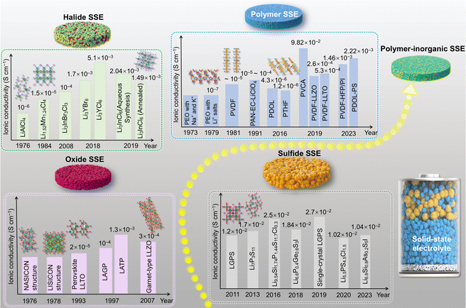
Currently the common SSEs mainly include sulfide electrolytes, oxide electrolytes, halide electrolytes and polymer electrolytes. This review classifies SSEs according to their types, gives an overview of the development of SSEs, and also compares the performance of various SSEs, as shown in Fig. 1 and 2.
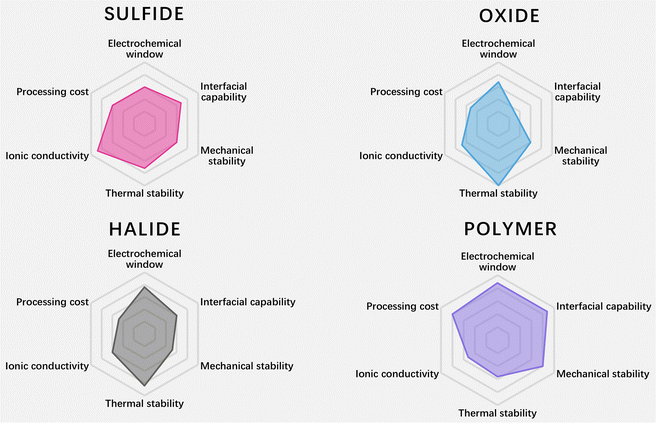 | ||
| Fig. 2 Radar plots of the performance properties of sulfide SSEs, oxide SSEs, halide SSEs and polymer SSEs (data are from ref. 8–10). | ||
In the 1970s, the discovery of a new type of inorganic lithium superionic conductor (LISICON)11 and sodium superionic conductor (NASICON)12 opened new windows for SSEs. The LISICON and NASICON as typical structures inspired many derivations and new design of oxide SSEs, such as Li1+xAlxGe2−x(PO4)3 (LAGP)13 and Li1+xAlxTi2−x(PO4)3 (LATP).14 Other structures such as perovskites Li0.34La0.51TiO2.94 (LLTO)15 and garnet-based SSEs Li7La3Zr2O12 (LLZO)16 were reported for their ionic conduction ability in 1993 and 2007, respectively. Oxide electrolytes have a wider electrochemical stability window and higher oxidative stability than sulfides. However, the room-temperature ionic conductivity of oxide electrolytes is generally lower than that of sulfides, and their larger crystal boundary resistance also limits their ionic conductivity.17,18
Sulfide SSEs are derived from oxide SSEs. In 2008, scholars at the University of Siegen in Germany discovered the sulfur germanium silver type electrolyte Li6PS5X (X = Cl, Br, I).19 In 2011, scholars from Tokyo Institute of Technology synthesized Li10GeP2S12 (LGPS),20 and its conductivity reached 1.2 × 10⁻² S cm−1. The Li7P3S1121 electrolyte reported in 2013 has an ionic conductivity of 1.7 × 10⁻² S cm−1. In 2016, Japan researchers discovered the LGPS-type SSE Li9.54Si1.74P1.44S11.7Cl0.3,22 and its bulk ion conductivity reached 2.5 × 10⁻² S cm−1. Generally speaking, the high ionic conductivity of sulfide SSEs comes from S2−, which has a larger ionic radius and polarizability than O2−.23 On the other hand, the electronegativity of S is small, and the interaction force between the neighboring skeleton ions is small, which is conducive to improving the concentration of free lithium ions.24,25 LGPS is the first solid electrolyte where the ionic conductivity at room temperature exceeds the electrolyte level, due to the three-dimensional skeleton structure of LGPS, which provides a fast transport channel for lithium ions. Moreover, the calculation results show that the activation energy of lithium ion diffusion between face-sharing tetrahedra is the lowest, LGPS and β-Li3PS4 structures have body-centered cubic lattice structure, and face-sharing tetrahedra occupy the whole cell, so materials with body-centered cubic lattice structure tend to have higher ionic conductivity.26 Besides, sulfide SSEs are relatively soft, and most can achieve close contact only through simple cold pressing, thus showing high cold-pressed ion conductivity, which is unmatched by oxide electrolytes.27
Halide SSEs have attracted attention because of their potentially high ionic conductivity, good deformability, and wide electrochemical window, but still suffer from drawbacks such as poor interfacial compatibility.28 In 1976, Weppner et al.29 developed a typical LiAlCl4 halide solid electrolyte for battery systems, displaying an ionic conductivity of ∼10−6 S cm−1. Then, various Li2MCl4 and Li2MBr4 compounds30 (where M is a transition metal) were developed to enhance ionic conductivity. In 2008, Koji Yamada et al.31 synthesized Li3InBr3Cl3 with an ionic conductivity of 10−4 S cm−1. In 2018, Asano et al.32 discovered Li3YCl6 and Li3YBr6 halide solid electrolytes, which exhibited a room temperature ionic conductivity of 5.1 × 10⁻⁴ S cm−1 and 1.7 × 10⁻³ S cm−1, respectively. Subsequently, Sun's research group33 achieved the synthesis of halide SSEs with high ionic conductivity (2.04 × 10⁻³ S cm−1) in aqueous solutions for the first time, and halide electrolytes once again attracted extensive attention from researchers.
Polymer SSEs are made up of a polymer matrix and alkali metal salts dissolved in that polymer matrix. Solid polymer electrolytes (SPEs) offer several advantages over liquid electrolytes, including excellent processability, no leakage, high energy density, shape flexibility, and reduced reactivity to the active electrode surface.34 In 1973, Fenton et al.35 were the first to discover that adding alkali metal salts to poly(ethylene oxide) (PEO) contributes to its ionic conductivity. Later, Berthier et al.36 suggested using lithium salt-containing PEO-based polymer electrolytes in solid-state lithium batteries. After that, other polymer electrolytes for Li+ conduction were developed, including poly(vinylidene fluoride) (PVDF),37 poly(acrylonitrile) (PAN),38 poly(dioxolane) (PDOL),39 poly(tetrahydrofuran) (PTHF),40 poly(vinyl chloride) (PVC),41etc. However, the above pure polymer solid electrolytes have low ionic conductivity at room temperature, which limits their application in solid-state batteries.
In recent years, solid polymer electrolytes (SPEs) have been combined with inorganic substances to enhance their performance. The glass transition temperature of polymer electrolytes can be effectively reduced by doping an inert filler in the polymer electrolyte, and the mechanical properties of the electrolyte can be effectively improved by adding an inorganic filler. In the past decade, researchers have turned more attention to active fillers, such as LATP, Li6.75La3Zr1.75Ta0.25O12(LLZTO) and so on. The active filler is the filler involved in the conductive process, because it can provide conductive lithium ions; lithium ions can be transferred not only in the polymer phase, but also in the active filler phase, so that the conductivity of the polymer electrolyte will be effectively improved.
This paper reviews the modulation of coordination structures, ion transport mechanisms and interfacial film-forming behavior in polymer–inorganic electrolytes in solid-state batteries under a wide temperature domain. Firstly, the ion transport mechanism in solid-state batteries is outlined, and the coordination structures and ion transport channels of polymer electrolytes are introduced, as well as the effects of lithium salt concentration, solvent type and inorganic nanofillers on lithium-ion transport. Then, the effects of coordination structures on electrolyte interfaces and electrochemical properties are discussed, as well as some advanced characterization tools. Finally, a comprehensive summary and outlook of future research directions are given.
2. Mechanisms of multiphase and multiscale ion transport in solid-state batteries
The migration of ions in solid-state batteries is a multiscale process consisting of mechanisms at different length scales, from the atomic scale to the device scale, as shown in Fig. 3a.8 At the atomic scale, mobile cations (e.g. Li+, Na+ or Mg2+) diffuse in the solid along favorable migration paths and can be regarded as ionic leaps between the basal stable sites and intermediate sub-stable sites of the backbone consisting of anions (e.g. O2−, S2−, or polyanionic parts). These centers and their energies are mainly determined by their local ionic coordination, i.e. the bonding environment, which is often tetrahedral or octahedral in crystalline compounds. Thus, the migration path of ions through a material is a function of the availability and interconnectivity of the different positions defined by the anionic arrangement. Compositional or structural inhomogeneities exhibited at the nano- to micrometer scale tend to dominate macroscopic ionic conductivity, either beneficially42–44 or harmfully.45,46 Prime examples of microstructural features are grain boundaries, i.e., contact surfaces between differently oriented microcrystals in polycrystalline samples, which can be quite different from bulk crystals in terms of structure and composition. Grain boundaries have been shown to increase the resistance to ion migration in most cases, which makes them undesirable in macroscopic samples. At the macroscopic scale, the ionic conductivity of solid materials is usually measured on macroscopic samples (usually particles) by impedance spectroscopy. Impedance spectroscopy is sensitive to all of the above structural features at all length scales and allows the measurement of the total conductivity of macroscopic ions. The critical impedance value ZDevice is obtained at the device level, which includes the contribution of materials other than the solid electrolyte, in particular the conductivity of interfacial phases that may be formed. Most solid electrolytes are unstable and decompose on contact with the electrode material. The interfaces formed are usually resistant to ion transport and are one of the main barriers to ion conduction.47,48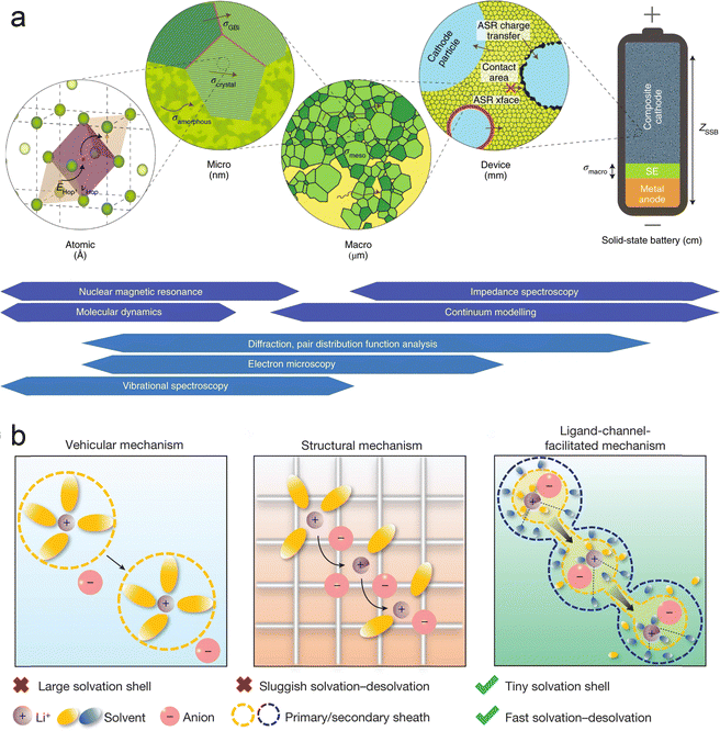 | ||
| Fig. 3 Multiphase and multiscale ion transport mechanism: (a) multiscale and corresponding characterization techniques. Reproduced with permission from ref. 8. Copyright 2019, Spring Nature. The arrows denote the transport of mobile cations in the SSE framework (in green). The major descriptors relating to ion transport are highlighted at each length scale: energy (EHop) and frequency of hops (νHop) at the atomic scale; the conductivity (σi) and area-specific resistance (ASRi) of defining features at larger scales; culminating in total device impedance, ZSSB. The techniques utilised to directly probe ion transport (that is, quantitatively determine the above descriptors; in dark blue) and complementary methods. The techniques utilized to directly probe ion transport (that is, quantitatively determine the above descriptors; in dark blue) and complementary methods used to aid interpretation (in light blue) are placed at their associated length scales. (b) Mechanisms of ion transport in battery electrolytes. Reproduced with permission from ref. 49. Copyright 2024, Spring Nature. | ||
It is generally accepted that lithium ions are transported in liquid electrolytes by two main modes, vehicular transport and structural transport (Fig. 3b).49 In vehicular transport, ions carry a layer of solvent molecules with them as they move, and larger solvent molecules can impede transport. In structural transport, ions form complexes with one or more solvent molecules and can therefore jump between molecules. Lu et al. found that very small solvent molecules can form two layers of sheaths around the lithium ion.49 The tiny inner sheath contains solvent molecules and counterions of lithium ions, and the outer sheath contains only solvent molecules; these solvent molecules pull the lithium ions out of the inner sheath, thus forming channels through which lithium ions can be transported, improving the mobility of the ions.
2.1. Comparison of ionic conductivity of polymer–inorganic solid electrolytes
SPEs exhibit remarkable processability and flexibility.50,51 Although they may not wet the electrodes as effectively as liquid electrolytes (LEs), their flexibility allows for favorable contact with the electrodes. Certain polymers can be in situ polymerized, leading to even better electrode/electrolyte interfacial properties. However, their soft nature also makes them unsatisfactory for suppressing lithium dendrites.50 Also, their ionic conductivity (ranging from 10−8 to 10−6 S cm−1 at RT) is far below the practical application requirements.52 Even though SPEs have a wider electrochemical stability window than LEs, they still face challenges in matching the high-voltage cathodes. Furthermore, some polymers, like PAN and PVDF, are unstable with the lithium metal anodes due to their specific functional groups.53 In order to enhance the comprehensive properties of polymer-based SSEs, they are usually combined with inorganic materials to prepare polymer–inorganic SSEs. Polymer–inorganic SSEs inherit the flexibility and scale-up processability of the polymer component and, hence, could be compatible with the large-scale and roll-to-roll fabrication processes used for conventional Li-ion batteries. In addition, polymer–inorganic SSEs might achieve enhanced ionic conductivity and stability, resulting from the inorganic component and synergistic interactions between the polymer and the inorganic phase, as discussed below.54In addition, research on polymer–inorganic composite solid electrolytes has been more and more extensive in recent years. Table 1 summarizes the ion conductivity, ion transfer number and electrochemical window of some reported polymer–inorganic solid electrolytes.
| Type | Polymer matrix | Inorganic filler | T/°C | σ/(S cm−1) | t + | ESW/V | Ref. |
|---|---|---|---|---|---|---|---|
| Inert fillers | PEO/LiTFSI | Al2O3 | 60 | 1.83 × 10⁻³ | — | 4.9 | 55 |
| PEO/LiClO4 | SiO2 | 60 | 1.2 × 10⁻³ | — | 5.5 | 56 | |
| PEO/LiClO4 | TiO2 | 40 | ∼10−4 | 0.47 | 5 | 57 | |
| PAN/LiClO4 | ZrO2 | 25 | 1.16 × 10⁻³ | — | — | 58 | |
| PAN/LiTFSI | SiO2 | 30 | 8.5 × 10⁻⁵ | 0.47 | 4.8 | 59 | |
| PAN/LiClO4 | α-Al2O3 | RT | 5.7 × 10⁻⁴ | 0.33 | — | 60 | |
| Active fillers | PAN/LiClO4 | LLZTO | 25 | 1.18 × 10⁻³ | — | — | 58 |
| PAN/LiClO4 | LLTO | 30 | 6.05 × 10⁻⁵ | 0.42 | — | 61 | |
| PEO/LiTFSI | Ga-LLZO | 30 | 7.2 × 10⁻⁵ | 0.39 | 4.6 | 62 | |
| PEO/LiTFSI | LLZTO | 30 | 3.16 × 10⁻⁶ | — | 4.6 | 63 | |
| PEO/LiTFSI | LAGP | 30 | 5 × 10⁻⁵ | — | 5.12 | 64 | |
| PEO-PVDF/LiTFSI | LLZO | 30 | 4.2 × 10⁻⁵ | — | — | 65 | |
| PVDF/LiFSI | BaTiO3–LLTO | 25 | 8.2 × 10⁻⁴ | 0.57 | — | 66 | |
| PVDF/LiFSI | MoSe2 | 25 | 6.4 × 10⁻⁴ | — | 4.7 | 67 | |
| PVDF–HFP/LiTFSI | LLZTO | 60 | 8.2 × 10⁻⁴ | 0.26 | 4.7 | 68 | |
| In situ polymerization | PDOL/LiTFSI | YSZ | 20 | 2.75 × 10⁻⁴ | 0.65 | 4.9 | 69 |
| PDOL/LiTFSI | PS | 30 | 2.2 × 10⁻³ | 0.88 | 5.2 | 70 | |
| P(DOL-TXE)/LiTFSI-LiDFOB | SN | RT | 4.06 × 10⁻⁴ | 0.881 | 5.1 | 71 | |
| PTHF/LiClO4 | BF3 | 60 | 2.3 × 10⁻⁴ | — | 4.5 | 72 |
2.2. Ion coordination and transport mechanisms at the molecular level
In SPEs, the interaction between ions and polymer chains is very important. Ions can form coordination complexes with polar groups in the polymer chain, and this coordination not only changes the conformation of the polymer, but also provides a channel for the movement of ions, whose coordination state determines their behavior and migration ability in the polymer matrix. He et al.73 found that the DMF-coated nanowires together with the PVDF polymer matrix create multiple and synergistic ceramic–polymer–liquid Li-ion transport channels to greatly enhance the ion transport efficiency (Fig. 4a). Wen et al.74 designed a molecular brush nanoparticle anchored to the surface of LLZTO (MB-LLZTO) to prepare a composite solid electrolyte; as shown in Fig. 4b, the binding of MB-LLZTO to PEO alters the diffusion path of lithium ions, and the fast ionic conductivity of the LLZTO surface improves the ionic conductivity by an order of magnitude. Yang et al.75 designed a low enthalpy and high entropy electrolyte, as shown in Fig. 4c, and found that CsPbI3 perovskite quantum dots largely destroyed the polymer chain, inhibited the crystallization of the polymer, adjusted the molecular orientation of the polymer, and enhanced its degree of disorder. This electrolyte inherently produces significant free ions and has high mobility, allowing it to effectively drive lithium-ion storage.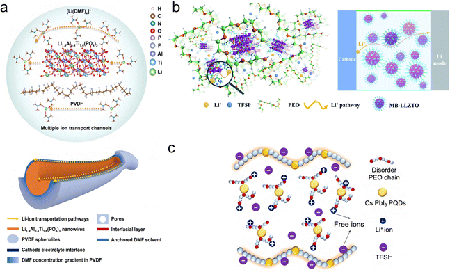 | ||
| Fig. 4 (a) Li-ion transport mechanism and multiple Li-ion transport channels in the PVLN-15 electrolyte. Reproduced with permission from ref. 73. Copyright 2021, Wiley. (b) Diagram of the Li+ diffusion pathway in the MB-LLZTO CPE. Reproduced with permission from ref. 74. Copyright 2019, Royal Society of Chemistry. (c) Schematic illustration of the low-enthalpy and high-entropy (LEHE) electrolyte with a disordered PEO chain and even more free ions through CsPbI3 quantum strengthening PEO–LiTFSI complexes. Reproduced with permission from ref. 75. Copyright 2024, Elsevier. | ||
2.3. Traditional ion transport mechanism of polymer–inorganic SSEs
The transport mechanisms of lithium ions in polymer-based electrolytes have been the subject of extensive research, and Fig. 5a outlines several key findings that have elucidated traditional ion transport in SPEs at the microscopic level over the past 40 years.76 As early as 1970, Armand et al. predicted that the movement of chain segments of the polymer backbone was related to the transport of ionic substances, especially for Li+, as shown in Fig. 5b.77 In 1980, Berthier et al.36 demonstrated using solid state NMR techniques that ionic transport in PEO-based SPE systems (usually “salts in polymers”) occurs mainly in the amorphous regions.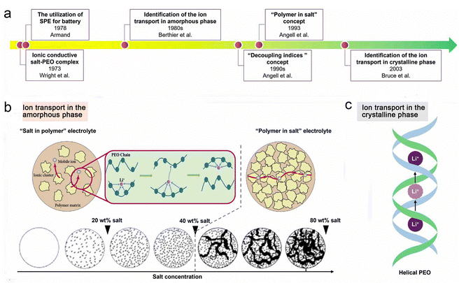 | ||
| Fig. 5 Transport behaviors of ionic species in SPEs. Reproduced with permission from ref. 76. Copyright 2022, IOP Publishing. (a) Evolution progress of the lithium-ion transport mechanism in SPEs. (b) Mechanism of ion transport in the amorphous phase of SPEs. (c) Mechanism of ion transport in the crystalline phase of SPEs. | ||
From another perspective, Stoeva et al. proposed that the crystalline phase of PEO-based SPEs has ionic conductivity with a well-defined microstructure (Fig. 5c).78 For the crystalline phase LiAsF6/PEO electrolyte, the relatively fast diffusion of Li+ is achieved by ionic substance hopping without involving the movement of the PEO chain segments (the diffusion paths are indicated by pink circles in Fig. 5c), and the PEO substrate remains “fixed” during the ionic conduction process. In contrast, the ionic conductivity of the crystalline LiAsF6/PEO electrolyte is almost an order of magnitude higher than that of the amorphous LiAsF6/PEO electrolyte. However, these crystalline-phase SPEs may achieve high ionic conductivity through low molecular weight PEO (<5000 g mol−1), but such polymers provide little self-supporting membranes, which hampers their practical application in lithium batteries.78–80
Since the 1990s, Angell et al.81 have systematically investigated the ion transport behavior of PEO-based electrolyte systems and revealed that Li+ transport is highly coupled to the motion of the polymer chain segments. In 1993, Angell et al. proposed the concept of “polymer-in-salt” electrolytes, in which large amounts (>50 wt%) of lithium salts with low melting points and high dissociation properties are used to form “decoupled” systems of SPEs.82 In this case, the transport of Li+ does not depend on the segmental motion of the polymer chains.
Smooth PEO is a semi-crystalline helical polymer with a degree of crystallinity (>60%) due to its regular and highly ordered structure.83,84 As mentioned above, ion transport in SPEs is largely dependent on chain segment movement and local relaxation of the polymer, with Li+ transport occurring mainly in the amorphous regions of the SPEs.85–88 As a result, the ionic conductivity of PEO-based SPEs is typically lower than 10−5 S cm−1 at RT,88 which limits their large-scale application in solid-state LMBs.
2.4. New mechanism of ion transport of polymer–inorganic SSEs
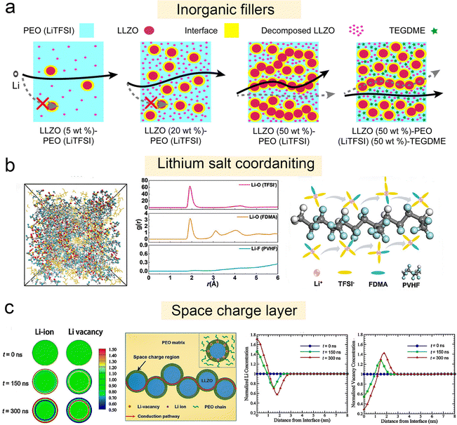 | ||
| Fig. 6 Solvation structure and new ion transport mechanism of polymer–inorganic SSEs. (a) Schematic of Li-ion pathways within LLZO (5 wt%)–PEO (LiTFSI), LLZO (20 wt%)–PEO (LiTFSI), LLZO (50 wt%)–PEO (LiTFSI), and LLZO (50 wt%)–PEO (LiTFSI) (50 wt%)–TEGDME composite electrolytes. Reproduced with permission from ref. 91. Copyright 2022, IOP Publishing. (b) Snapshots of the MD simulation boxes of PVHF–FDMA–SPE; radial distribution function (RDF) plots of Li–O (TFSI−), Li–O (FDMA), and Li–F (PVHF); schematic diagram of the Li-FDMA-3TFSI-solvation structure's transportation mechanism in PVHF–FDMA–SPE. Reproduced with permission from ref. 93. Copyright 2024, Wiley-VCH Gmbh. (c) Formation of the space charge region at the Ga-LLZO/PEO interface. Reproduced with permission from ref. 62. Copyright 2019, American Chemical Society. Evolution of the normalized Li+ (cLi+) and vacancy concentration (cV) from 0 to 300 ns; distributions of the lithium ion concentrations, and distributions of the vacancy concentrations from the surface to the center of the Ga-LLZO nanoparticle along the radial direction at t = 0, 150, and 300 ns; schematic illustration of the fast ionic conduction pathway along the space charge regions. | ||
2.5. Challenges in lithium-ion transport and interface stability
The electrolyte, which physically interacts with all other components, stands out as the most distinctive component in a lithium-ion battery. In LIBs, the SPE plays the important role of an electronically insulating separator because of its high flexibility, ease of processing, good interfacial contact, good thermal stability and high mechanical strength.However, in the process of practical application, SPEs still face some key challenges:
(1) Low ionic conductivity at room temperature. The conduction of lithium ions in the SPE is highly coupled with the chain segment motion of the polymer, which typically has high crystallinity at RT. Thus, the ionic conductivity of the SPE is low, which seriously limits its practical application.
(2) Lithium ion transport determined by multi-factors. Different concentrations of lithium salt will affect the conductivity of the electrolyte and the cycle performance of the battery. Inorganic fillers can improve the mechanical properties and conductivity of the battery, and play a certain auxiliary role in the transport of lithium ions. Additives can improve the stability of the electrolyte and the chemical activity of the electrode material, which affects the transport efficiency of lithium ions and the performance of the battery. All these factors have significant effects on lithium-ion transport.
(3) Unstable electrode/electrolyte interphases. The electrochemical window is narrow, making side reactions likely to occur at the electrode interface under high voltage.
Based on the problems mentioned above, many researchers have proposed some improvement strategies. In this review, advances addressing the issues and design strategies of polymer–inorganic SSEs are summarized.
3. Regulation strategies for improving the ionic conductivity of polymer–inorganic SSEs
3.1. High concentration and locally high concentration SPEs
In recent years, polymer-in-salt (PIS) solid state electrolytes with lithium salt content exceeding 50 wt% have received renewed attention (Fig. 7a). High concentrations of lithium salts can maximally inhibit the crystallization of the polymer matrix at low temperatures, resulting in continuous amorphous regions that facilitate fast Li+ transport. In addition, fast ion diffusion pathways can be formed by cation/anion cluster aggregation. As a result, PIS solid electrolytes exhibit high ionic conductivity at ambient temperatures (up to 0.36 mS cm−1 at 25 °C).109 Wang's group designed a class of locally high-concentration solid polymer electrolytes based on polymer blends, which are termed Li–polymer in F diluter (LPIFD) (Fig. 7c).110 The single-phase LPIFD delivers an ionic conductivity of 3.0 × 10⁻⁴ S cm−1, and enables the Li anode to reach a high coulombic efficiency of 99.1% and a critical current density of 3.7 mA cm−2.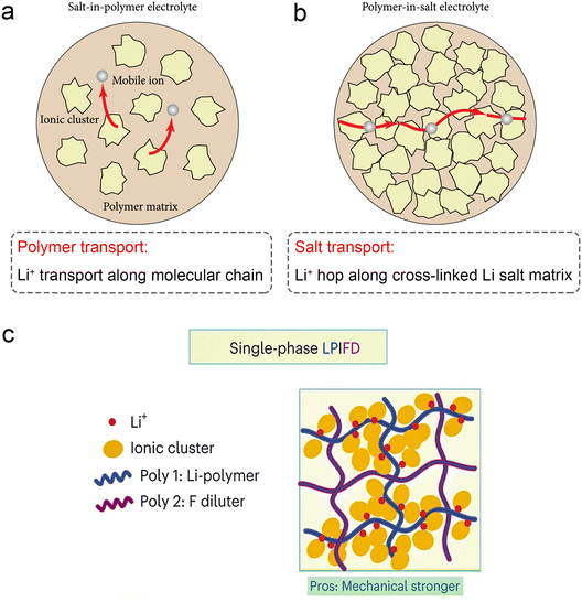 | ||
| Fig. 7 Schematic illustration of lithium-ion transport (a) in a salt-in-polymer electrolyte and (b) in a polymer-in-salt electrolyte. Reproduced with permission from ref. 59. Copyright 2021, Science Partner Journal. (c) The single-phase LPIFD SPEs. Reproduced with permission from ref. 110. Copyright 2024, Spring Nature. | ||
3.2. Addition of inorganic nanofillers
The structure and ion transport mechanism of organic–inorganic composite electrolytes depend on the nature and content of the inorganic materials in them. When the inorganic filler content is low, the structure and Li+ transport mechanism of the composite electrolyte are the same as that of the all-solid polymer electrolyte.111 Traditional inorganic fillers are mainly inert fillers, including SiO2, Al2O3, TiO2, MgO, ZrO2, etc., which do not have ion transport capacity themselves, but promote the formation of penetration channels between the polymer chain and the filler by reducing the crystallinity of the polymer matrix, thus effectively improving the electrochemical performance of the composite polymer electrolyte (CPE). Cui et al.56 presented a method for in situ production of inorganic fillers in SPEs (Fig. 8a). Due to this in situ polymerization, SiO2 forms a continuous dispersed phase in the polymer. As a result, more contact area is provided for Lewis acid-based interactions. In addition, monodisperse SiO2 effectively inhibits PEO crystallization and promotes the movement of the polymer chain segments, and as a result, the SiO2–PEO CPE exhibits an excellent ionic conductivity of 4.4 × 10⁻⁵ S cm−1 at 30 °C (Fig. 8c). Hu et al. compared the effects of different sizes of ZrO2 (diameters of 220, 365, and 470 nm, respectively) on the formation of ion-permeable networks in PAN–LiClO4, and the results showed that the ionic conductivity of ZrO2–PAN CPEs increased with the decrease of ZrO2 size.58 In contrast, ZrO2 (220 nm) can form a more effective ion transport interface. Therefore, the ZrO2 (220 nm)–PAN CPE has the best ionic conductivity of 1.16 × 10⁻³ S cm−1. Wu et al. constructed a crosslinked dual network structure of Al2O3 fillers and polymers by the in situ sol–gel method (aluminum sec-butoxide as the aluminum source) (Fig. 8b).55 Al2O3 nanoparticles were uniformly dispersed without agglomerates and interconnected with the PEO chains to form a dual network skeleton in 3D space. The prepared CPEs not only exhibited excellent ionic conductivity but also showed higher Young's modulus (116.49 MPa) at RT compared to pure PEO electrolytes (60.78 MPa for pure PEO electrolytes).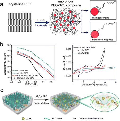 | ||
| Fig. 8 The addition of traditional inorganic fillers to reduce the crystallinity. (a) Schematic figures showing the procedure of in situ hydrolysis and interaction mechanisms among PEO chains and SiO2. (b) Arrhenius plots of ionic conductivity and electrochemical stability windows of the ceramic-free SPE, PEO-fumed SiO2 CPE, ex situ CPE, and in situ CPE. Reproduced with permission from ref. 56. Copyright 2016, American Chemical Society. (c) The mechanism diagram of reducing polymer crystallinity. Reproduced with permission from ref. 55. Copyright 2021, Elsevier. | ||
3.3. Involvement of residual solvents in Li coordination
Recent reports have begun to focus on the use of residual solvents to improve their contact with the electrodes. It is well known that fundamental issues, such as the bonding state and content of residual solvents, are still controversial. However, these factors are particularly important in terms of lithium-ion transport, interfacial stability, and battery performance. Many studies have reported the excellent electrochemical performance of polymer-based solid-state batteries, but the real working principle remains highly controversial. The focus is on whether the organic solvents (NMP, DMF, etc.) remain in the polymer's native structure. Typically, solvated complexes [solvent–Li+] can interact with the polymer chains to achieve high ionic conductivity and enhanced oxidation resistance of the electrolyte. However, the application reliability of such electrolytes faces the challenge of precisely controlling the effects of residual solvents to achieve stable operation. Increasingly, research focuses on limiting residual solvents to improve the electrochemical stability of polymer electrolytes. This includes adapting the preparation process, introducing inorganic fillers, and designing compatible quasi-ionic liquid/polymer electrolytes.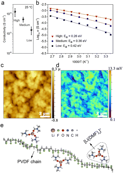 | ||
Fig. 9 Effects of residual DMF on ionic conduction in PVDF–LiFSI electrolytes: (a) ionic conductivity (25 °C) and (b) Arrhenius plots of the high-, medium- and low-DMF electrolytes and low-DMF electrolytes. (c) The height map of a PVDF–LiFSI electrolyte film. (d) The corresponding IR intensity map of C![[double bond, length as m-dash]](https://www.rsc.org/images/entities/char_e001.gif) O vibration of DMF at 1670 cm−1. (e) A simple schematic diagram of the structure of [Li(DMF)x]+ (x ≤ 3.29) in the PVDF–LiFSI electrolyte. Reproduced with permission from ref. 115. Copyright 2020, Wiley-VCH Gmbh. O vibration of DMF at 1670 cm−1. (e) A simple schematic diagram of the structure of [Li(DMF)x]+ (x ≤ 3.29) in the PVDF–LiFSI electrolyte. Reproduced with permission from ref. 115. Copyright 2020, Wiley-VCH Gmbh. | ||
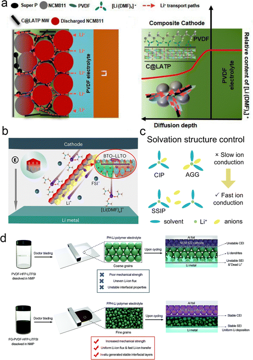 | ||
| Fig. 10 Inorganic fillers anchor solvents to promote lithium salt coordination. (a) Physical property of the C@LATP NW filler and PCL-NCM cathode. Schematic of multiple Li+ transport channels and diffusion of [Li (DMF)]x+ in the composite cathode with C@LATP NW. Reproduced with permission from ref. 116. Copyright 2024, Royal Society of Chemistry. (b) Illustration of the Li salt dissociation and Li+ transport by the coupled BTO–LLTO in the PVBL electrolyte. Reproduced with permission from ref. 66. Copyright 2023, Spring Nature. (c) Solvation structure control. Reproduced with permission from ref. 67. Copyright 2023, Spring Nature. (d) Schematic illustration of the influence of fluorinated graphene on the properties of polymer electrolytes: synthesis process of the common PVDF–HFP–LiTFSI (PH-Li) polymer electrolyte and the influence of its inherent shortcomings on full-cell cycling. Synthesis process of the fluorinated graphene reinforced PVDF–HFP–LiTFSI (FPH-Li) polymer electrolyte and the mechanism of its advantages for improving the cycling stability of the full cell. Reproduced with permission from ref. 117. Copyright 2020, Wiley-VCH Gmbh. | ||
4. Electrode–electrolyte interfaces
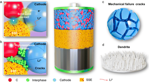
In recent years, the emergence of solid electrolytes has fundamentally solved the safety hazards of traditional liquid lithium-ion batteries, and is expected to achieve high energy density. However, due to the lack of fluidity of solid electrolytes, in a series of problems such as a small solid–solid contact area and increased impedance occur, and these interface problems have become the bottleneck restricting the development of solid-state batteries. As shown in Fig. 11, the solid electrolyte interface mainly faces the following problems: interface electron/ion transport is poor, interface side reactions generate a high impedance phase, stress-induced particle cracks occurs and dendritic growth.Compared with traditional liquid electrolytes, solid electrolytes do not have fluidity, so it is difficult to penetrate into the interface of the entire electrode and diaphragm, making ion/electron transmission slow at the interface, affecting the charge and discharge rate.118 At the same time, the undesirable electron transport at the electrode/electrolyte interface can also induce chemical side reactions to form a passivation mesophase leading to high interface resistance,119 which is a key factor affecting the electrochemical performance of solid-state batteries. Besides, during the electrochemical cycling of the battery, the volume changes of the electrodes that occur during repeated charging and discharging cause a loss of interface contact and also increase the interface impedance. And in ASSBs, the physical and mechanical stability of the solid electrolyte and electrodes isn't great, which can lead to structural stress at the electrode/electrolyte interface. As the electrochemical cycles continue, this structural stress keeps building up, and even stress-induced particle cracks, ultimately affecting the battery's electrochemical performance. In addition, under working conditions, the charge and discharge rates as well as the operating voltage are key factors affecting the electrochemical stability of the interface. High charge and discharge rates can induce the formation of lithium dendrites on the lithium anode during the deposition and dissolution process,120 which can lead to battery short circuits and reduce the electrochemical performance of the battery.
In summary, the solid–solid interface problem is the main reason for the poor electrochemical performance of solid-state batteries. At present, the research on the interface of solid-state batteries has also achieved remarkable results, and this review summarizes the relevant results of the interface between the cathode and anode.
4.1. Electrolyte–cathode interface
The fluorinated electrolyte-induced F-rich CEI has been shown to improve the cycling stability of various cathode materials including LLOs, NCM811, etc. However, the high cost of fluorinated electrolytes will hinder the promotion of this strategy to some extent. Based on the basic idea of the LiF-rich CEI strategy, fluoride-rich interfacial modulation is another feasible and effective method to achieve CEI modulation in LLOs. Wu et al.111 designed a PVDF-based composite electrolyte by adding MoSe2 sheets. The in situ reactions between MoSe2 and Li metal generate a Li-conducting Li2Se component in the SEI, which could suppress the DMF decomposition, improve the coulombic efficiency and enhance the interfacial ion transport kinetics (Fig. 12a). Wang et al.110 designed a LPIFD electrolyte by combining two miscible polymers: Li–polymer (polymer-in-salt) and F diluter (inert fluorinated polymer) (Fig. 12b). The Li–polymer (polymer-in-salt) ensures continuous Li-ion conduction channels and contributes to the SEI, while the F diluter (inert fluorinated polymer) provides mechanical strength. Studies reveal that the single-phase LPIFD, which is based on a miscible polymer blend, lacks phase boundaries and forms an organic-less and LiF-rich SEI, effectively suppressing lithium dendrites. Lu et al. designed an artificially enhanced CEI, with the main idea being to reduce the irreversible oxygen release and improve the stability of the material surface by constructing a high-pressure stable spinel combined with the introduction of a strong M–F bond.122 More importantly, the F-rich structure on the material surface is beneficial for inducing the uniform deposition of LiF, which is conducive to the improvement of the lithium-ion transport properties. In addition, the strong polarity of F substitution facilitates the formation of a stable CEI layer. Compared with the conventional fluorine doping modification, the gradient doping method they developed avoids the conductivity drop and capacity loss caused by deep doping.
4.2. Electrolyte–anode interface
Heiskanen et al. proposed a mechanism for the evolution of a SEI.123 Initially, the SEI was mainly composed of lithium ethylene decarbonate (LEDC) and LiF. However, LEDC is unstable and decomposes to produce a complex mixture of products. Since some of these components are soluble in electrolytes or gases, the remaining insoluble SEI becomes more porous. In addition, the remaining insoluble components are mainly inorganic: LiF, Li2CO3 and Li2O. The remaining insoluble components become inner, more inorganic SEI. At the same time, as the SEI becomes more porous, the electrolyte can reach the surface of the graphite electrodes, leading to further reduction of the electrolyte, generating additional LEDC and LiF. The new electrolyte reduction reaction results in the generation of external SEIs. In terms of composition and structure, most SEI films have a “mosaic” structure, consisting of disordered inorganic salts (such as lithium carbonate (Li2CO3), LiF) and organic substances (such as LEDC). It has also been shown that the electrochemical performance of batteries can be improved under certain conditions by modulating the interface to form a SEI film with a multilayer structure. The inner layer of this kind of electrode/electrolyte interface membrane is mainly composed of inorganic materials such as LiF, Li2CO3 and Li2O, and it has a dense and compact structure with good thermodynamic stability, but it is easy to cause a significant increase in the interfacial impedance.124 The outer layer is mainly composed of organic materials such as lithium alkoxide (ROLi) and LEDC, which have a loose and porous structure and relatively poor thermodynamic stability. Therefore, the nature of the electrode/electrolyte interfacial film greatly affects the electrochemical performance of LIBs. The structure of the electrolyte not only determines the ion transport mechanism and the basic electrochemical properties of the electrolyte (conductivity, Li+ transfer number), but can also affect the compatibility of the electrolyte with the electrode. | ||
| Fig. 13 Schematic illustrations showing the SEI swelling behavior and solvent co-intercalation mechanism of the Gr anode for pristine (a) and LiDFP-modified systems at −20 °C. (b) Reproduced with permission from ref. 132. Copyright 2023, Wiley-VCH Gmbh. | ||
To solve these problems, Wang's team proposed a new electrolyte based on a polymer blend – LPIFD.110 They performed XPS analysis of the SEI on the surface of the recycled Li anode for three LPIFDs, as shown in Fig. 16a–c. LPIFD promoted the formation of an inorganic SEI due to the presence of high concentration of LiFSI salt. Compared to the SEI observed in PEO–LPIFD with a significantly reduced carbon ratio (Fig. 14a) and the organic-rich SEI in PMMA–LPIFD (Fig. 14b), the atomic ratio of different elements of SEI in PTFEP–LPIFD remained almost constant from the surface to the inner layer (Fig. 14c). In the PTFEP–LPIFD system, the LiF-rich and uniform SEI structure is the result of the homogeneous distribution of PTFEP in PVDF–HFP. There is a significant repulsion between LiF and Li metal, resulting in a weak binding force and a high interfacial energy. This characteristic allows the SEI to bear less stress during the process of Li plating and stripping, thus maintaining good mechanical strength. In addition, sufficient LiF also promoted the lateral deposition of Li metal and inhibited the formation of Li dendrites. Therefore, the uniform and LiF-rich inorganic SEI in PTFEP–LPIFD plays a key role in preventing the formation of Li dendrites. In general, the inorganic-abundant interphases with a large electrochemical window and high Young's modulus can inhibit electrolyte decomposition and dendrite formation. Wang et al.135 evaluated the interfacial composition of recycled batteries by XPS analysis. Significant LiF signals, LiBxOyFz and LixBFy were observed on the PLLDB-anode (Fig. 14d). Combined with the results of the C1s spectroscopy, it can be inferred that a robust LiF-containing SEI layer is formed, which subsequently inhibits the decomposition of the electrolyte. In addition, SEM images of the cycled PLLDB-anode demonstrate the stability of the SEI with a smooth and uniform morphology (Fig. 14e). Guo's team136 also analyzed the SEI components formed in the electrolyte by XPS, as shown in Fig. 14f. In the case of the polymer electrolyte, it shows lower Li2CO3 intensity, and an additional signal of CF3 can be detected. The existence of CFx is further supported by the F 1s spectra, where two other peaks at ∼685 and ∼686.8![[thin space (1/6-em)]](https://www.rsc.org/images/entities/char_2009.gif) eV, corresponding to LiF and B–F, respectively, suggest the preferred reactions of FDMA and DFOB− with Li. According to the above results, the relative composition of lithium compounds at different depths is shown in Fig. 14g. In polymer systems, LixBOyFz and LiF substances dominate SEI chemistry. With the increase of sputtering depth, the content of LixBOyFz decreases, while the content of LiF increases. Thus, the SEI in the polymer system can be basically attributed to LixBOyFz in the outer layer and LiF in the inner layer.
eV, corresponding to LiF and B–F, respectively, suggest the preferred reactions of FDMA and DFOB− with Li. According to the above results, the relative composition of lithium compounds at different depths is shown in Fig. 14g. In polymer systems, LixBOyFz and LiF substances dominate SEI chemistry. With the increase of sputtering depth, the content of LixBOyFz decreases, while the content of LiF increases. Thus, the SEI in the polymer system can be basically attributed to LixBOyFz in the outer layer and LiF in the inner layer.
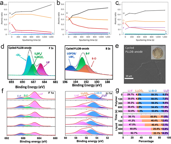 | ||
| Fig. 14 SEI composition of the polymer electrolyte with a lithium anode. (a)–(c) Quantified atomic composition ratios of the SEI at different sputtering times (0, 120, 300, 600 and 1200 s from top to bottom) for PEO-LPIFD (a), PMMA-LPIFD (b) and PTFEP-LPIFD (c). Reproduced with permission from ref. 110. Copyright 2024, Spring Nature. (d) XPS spectra of F 1s and B 1s of the PLLDB-anode. (e) SEM images of the surface morphologies of the cycled Li metal anode dissembled from PLLDB. Reproduced with permission from ref. 135. Copyright 2023, American Chemical Society. LMAs cycled in Li||Li coin cells with the designed polymer electrolyte: (f) XPS depth profiles of F 1s and Li 1s and (g) relative compositions of Li-containing species. Reproduced with permission from ref. 136. Copyright 2023, Spring Nature. | ||
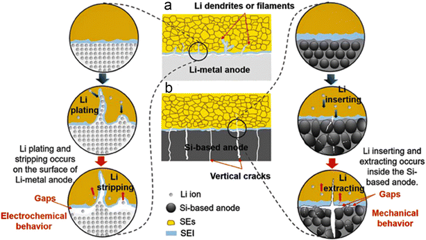 | ||
| Fig. 15 Mechanisms of the interfacial gaps formed by (a) Li-metal anodes and (b) Si-based anodes with the SEs. Reproduced with permission from ref. 139. Copyright 2023, Wiley-VCH Gmbh. | ||
As shown in Fig. 16a, Masuda et al. performed an in situ XPS experiment to characterize the SEI formation at the interface between the Si electrode and the LLZTO electrolyte during the first cycle with Li metal as the counter electrode.140 The Li 1s peak in the XPS spectra shows several lithiation products consisting of Li2O, Li2CO3, Li4SiO4 and LixSi, and the same lithiation products are also demonstrated in the Si 2p and O 1s spectra. Notably, the presence of Li2O and Li2CO3 suggests that trace oxygen species and carbon dioxide may be derived from the reaction products of the XPS chamber or LLZTO with the lithium silicide surface. In general, the small number of interfacial products and the high coulombic efficiency of the half-cell indicate that the side reactions at the interface between the Si anode and the LLZTO electrolyte are suppressed. Our team proposed a Si@SiO2@LPO@C composite negative electrode and applied it to a liquid electrolyte and a PEO/LATP ASSE, respectively.141 The TEM images in Fig. 16b show the cycling silicon composite particles and the SEI layer of the disassembled ASSB after 200 cycles. Notably, conformal particles and uniform SEI layers were observed from the ASSB, and the LiTFSI in the ASSE contributed to the formation of LiF nanocrystal-rich SEI layers with mechanical robustness and high ionic conductivity. For PEO–LiTFSI solid electrolytes, LiTFSI is preferentially reduced over PEO, and thus the decomposition of LiTFSI to produce LiF is thermodynamically favorable.
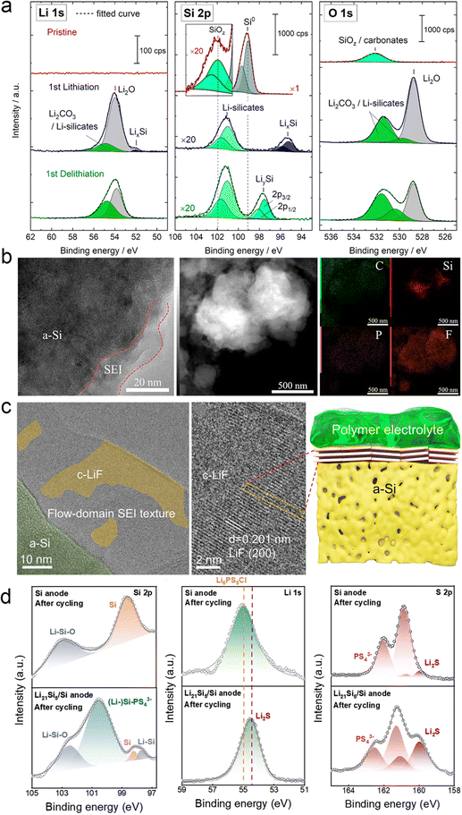 | ||
| Fig. 16 SEI components deposited on the Si anode surface. (a) Li 1 s, Si 2p, and O 1 s spectra of the Si electrode at different states: pristine state, after the first lithiation, and after the first delithiation process. Reproduced with permission from ref. 140. Copyright 2020, American Chemical Society. (b) TEM images, HADDF-STEM images, and the corresponding elemental distributions of the Si@SiO2@LPO@C composite anode after 200 cycles from the ASSB. Reproduced with permission from ref. 141. Copyright 2022, Elsevier. (c) Cyro-TEM and high-resolution TEM image of the surface SEI on the PS–Ag–C electrode after 500 cycles. The schematic diagram of the SEI formed on the surface of cycled PS–Ag–C in a solid-state cell. Reproduced with permission from ref. 142. Copyright 2023, Royal Society of Chemistry. (d) XPS tests of Si-ASSBs and Si/Li21Si5-ASSBs after 50 cycles. Reproduced with permission from ref. 143. Copyright 2024, Royal Society of Chemistry. | ||
Besides, our team proposed the design of highly dense Ag nanoparticles decorated with porous microsized Si (PS–Ag-), which is coated by thin-layer carbon (PS–Ag–C) working as a high-performance anode for boosting SSB performance.142 As shown in Fig. 16c, a large amount of LiF on the electrode surface was observed in the SEI region by cryo-TEM. It was observed that the crystal plane of LiF particles showed a well-oriented flow-domain like pattern, which are parallel to the surface of PS. Then, Zhang’ team developed a Si/Li21Si5 composite anode with the rational architecture and optimized ratio of Li21Si5 and pure Si.143,144 They disassembled the cells after the cycle and analyzed the role of the Li21Si5 alloy in the anode. Fig. 16d shows the results of its XPS and cross-section SEM characterization. After adding the Li21Si5 alloy, (Li-) Si–PS43− (100.5 eV) and Li–Si (97.6 eV) were found on the surface of the anode, indicating that the Li21Si5 alloy can continue to provide efficient ion/electron conductive channels and stable lithium supply, making the electrochemical reaction of SSBs more complete. This is further supported by the addition of Li2S in the Li 1s and S 2p orbitals. As an electronic insulator, Li2S can prevent further decomposition of Li6PS5Cl in time to build a stable SEI. Therefore, an efficient transmission channel is successfully constructed inside the anode.
4.3. Advanced characterization techniques on lithium-ion transportation and interphases
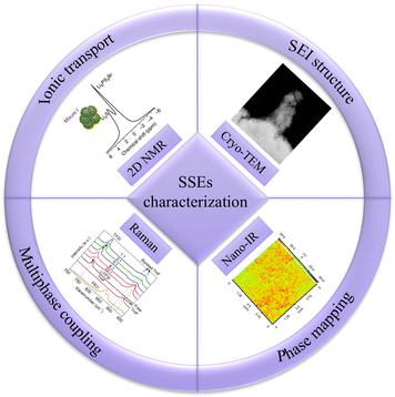
In SSEs, information about the transport of lithium ions and the interface can be obtained through a variety of characterization techniques; Fig. 17 illustrates some of these characterization techniques, including two-dimensional nuclear magnetic resonance spectroscopy (2D NMR), cryogenic transmission electron microscopy (cryo-TEM), Raman spectrum and nano infrared spectrum (Nano-IR).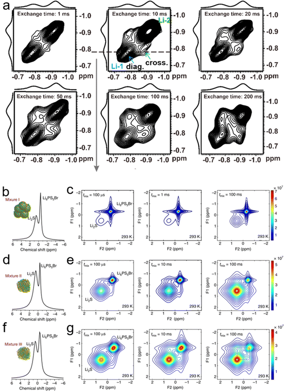 | ||
| Fig. 18 (a) The 2D 7Li–7Li exchange spectrum of IM240-PEO/Li+. This spectrum was acquired using an exchange time of 1 to 200 ms at 305 K. Reproduced with permission from ref. 145. Copyright 2020, MDPI. NMR measures the spontaneous lithium-ion transport between the Li6PS5Br solid electrolyte and the Li2 S cathode. (b), (d) and (f) One-dimensional (1D) 7Li magic angle spinning (MAS) spectra corresponding to the Li6PS5Br–Li2S cathode mixtures: (b) mixture I, where Li2S is micron-sized, (d) mixture II, where Li2S is nanosized and (f) mixture III, where nanosized Li2S is thoroughly mixed with Li6PS5Br. (c), (e) and (g) Two-dimensional (2D) 7Li–7Li exchange spectra (2D-EXSY) recorded at a 7Li resonance frequency of 155.506 MHz and a spinning speed of 20 kHz at RT for short (100 μs) to long mixing times tmix (100 ms) for (c) mixture I, (e) mixture II, and (g) mixture III. Reproduced with permission from ref. 48. Copyright 2017, Spring Nature. | ||
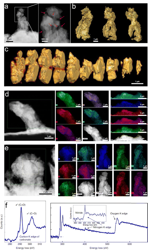 | ||
| Fig. 19 3D morphology and chemistry of the Li-containing dendrites plated using the baseline succinonitrile-incorporated solid polymer electrolyte (SN-SPE). (a) Cryogenic annular dark-field scanning transmission electron microscopy (ADF-STEM) image and (b) 3D reconstruction of a representative filament obtained by cryogenic tomography based on ADF-STEM images. (c) 3D Cross-section analyses of the filament in (a). (d) and (e) Energy-dispersive X-ray spectroscopy (EDS) maps of several filaments from different regions. The results show that O, C, N, S, and F are distributed throughout the whole filament in all regions. (f) Electron energy-loss spectroscopy (EELS) of the filament. C, N, and O species are identified in the spectra. Reproduced with permission from ref. 147. Copyright 2022, Spring Nature. | ||
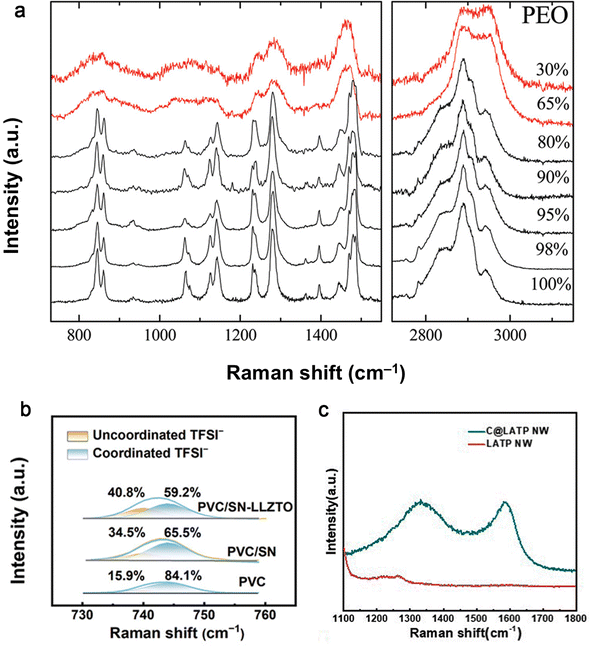 | ||
| Fig. 20 Raman spectra of (a) PEO and of PEO/Na+-MMT nanocomposites with different polymer concentrations at ambient temperature. Reproduced with permission from ref. 148. Copyright 2011, American Chemical Society. (b) PVC, PVC/SN and PVC/SN-LLZTO SEs in the range of 730–760 cm−1. Reproduced with permission from ref. 149. Copyright 2024, Wiley-VCH Gmbh. (c) The C@LATP NW and LATP NW. Reproduced with permission from ref. 116. Copyright 2024, Royal Society of Chemistry. | ||
![[double bond, length as m-dash]](https://www.rsc.org/images/entities/char_e001.gif) O groups of DMF in PVMS-15 and PVDF electrolytes.66 On the surface of the PVMS-15 electrolyte, the intensity of the absorption peaks remained low and consistent (Fig. 21c), which favored the formation of a dense SEI and inhibited the decomposition of DMF. In contrast, the DMF solvent aggregates around the PVDF spherical crystals (Fig. 21d), which always causes inhomogeneous lithium deposition and rapid lithium dendrite growth. Thus, the adsorption between MSs and PVDF not only produced a dense electrolyte, but also led to a uniform solvent distribution. The distribution of DMF in 3 wt% C@LATP NW in the PCL-NCM cathode was further examined by nano-IR (Fig. 21e and f).116 The strength of the C
O groups of DMF in PVMS-15 and PVDF electrolytes.66 On the surface of the PVMS-15 electrolyte, the intensity of the absorption peaks remained low and consistent (Fig. 21c), which favored the formation of a dense SEI and inhibited the decomposition of DMF. In contrast, the DMF solvent aggregates around the PVDF spherical crystals (Fig. 21d), which always causes inhomogeneous lithium deposition and rapid lithium dendrite growth. Thus, the adsorption between MSs and PVDF not only produced a dense electrolyte, but also led to a uniform solvent distribution. The distribution of DMF in 3 wt% C@LATP NW in the PCL-NCM cathode was further examined by nano-IR (Fig. 21e and f).116 The strength of the C![[double bond, length as m-dash]](https://www.rsc.org/images/entities/char_e001.gif) O group was much stronger on C@LATP NW, suggesting that most of the DMFs were anchored to the surface of the high specific surface area C@LATP NW because of their higher adsorption energy.
O group was much stronger on C@LATP NW, suggesting that most of the DMFs were anchored to the surface of the high specific surface area C@LATP NW because of their higher adsorption energy.
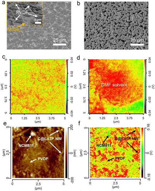 | ||
Fig. 21 (a) Surface SEM image of the PVMS-15 electrolyte. The inset is the surface of the PVMS-15 electrolyte obtained from FIB-SEM. (b) Surface SEM image of the PVDF electrolyte. Nano-IR overlap of the C![[double bond, length as m-dash]](https://www.rsc.org/images/entities/char_e001.gif) O vibration of DMF solvent in the PVMS-15 (c) and PVDF (d) electrolytes. The red color area means the existence of DMF solvent while the green color area means the absence of DMF solvent. Reproduced with permission from ref. 67. Copyright 2023, Spring Nature. (e) AFM image of the PCL-NCM cathode. (f) Nano-IR overlap of the C O vibration of DMF solvent in the PVMS-15 (c) and PVDF (d) electrolytes. The red color area means the existence of DMF solvent while the green color area means the absence of DMF solvent. Reproduced with permission from ref. 67. Copyright 2023, Spring Nature. (e) AFM image of the PCL-NCM cathode. (f) Nano-IR overlap of the C![[double bond, length as m-dash]](https://www.rsc.org/images/entities/char_e001.gif) O vibration of DMF solvent at 1663.27 cm−1. Reproduced with permission from ref. 116. Copyright 2024, Royal Society of Chemistry. O vibration of DMF solvent at 1663.27 cm−1. Reproduced with permission from ref. 116. Copyright 2024, Royal Society of Chemistry. | ||
5. Electrochemical performances
The solid state battery assembled by a polymer–inorganic solid electrolyte not only has high ionic conductivity and a wide electrochemical window, but also good electrochemical performance, including high voltage cathode, high mass load, a wide temperature range and low external pressure. Table 2 summarizes the relevant electrochemical properties of some polymer–inorganic SSBs. Through modification and structural design, the electrochemical performance of the electrolyte can be improved to enhance the energy density and cycle life of solid-state batteries.| Electrochemical performance | Polymer matrix | Li||Li symmetrical cell cycle life | Cathode | Cathode voltage/V | Full cell cycle life and capacity retention | Loading of cathode/(mg cm−2) | Ref. |
|---|---|---|---|---|---|---|---|
| High voltage cathode | PEO-LLZTO | — | LiCoO2 | 4.5 | 0.2C 60 °C 200 cycles retaining 110.4 mA h g−1 | 1.5–2 | 151 |
| PEO-LLZNO | — | LFP | 5.2 | 0.5C 60C 150 cycles 97% retention | 2 | 152 | |
| PEO-LLZTO | 60 °C 0.2 mA cm−2 400 h | LFP | 5.5 | 0.1C 60 °C 100 cycles 83% retention | 4.7 | 153 | |
| PEO-LLZTO | 55 °C 0.5 mA cm−2 >680 h | LFP | 5 | 0.2C 55 °C 100 cycles 98.6% retention | 2–3 | 154 | |
| PEO@ZIF-8 | — | NCM811 | 4.9 | 0.2C 60 °C 149.8 mA h g−1 2.8–4.3 V 100 cycles 83.2% retention | — | 155 | |
| PEGDME | 0.2 mA cm−2 2500 h | NMC532 | 4.3 | 0.2C 100 cycles 97% retention | 3–4 | 156 | |
| High loading capacity | PVC/SN-LLZTO | — | NCM811 | 4.96 | 0.1C RT 100 cycles 72.4% retention | 8.3 | 149 |
| PEO-PAN | — | NCM811 | 4.9 | 0.35 mA cm−2 50 °C 100 cycles 78% retention | 23 | 157 | |
| PEO-LLZTO | 0.2 mA cm−2 >960 h | LFP | 4 | 0.1 mA cm−2 155.7 mA h g−1 | 11 | 158 | |
| PEGDA | 25 °C 0.5 mA cm−2 2000 h | LFP | — | 0.1C 25 °C 55 cycles 96.4% retention | 16.43 | 159 | |
| BPCT-PE | 0.5 mA cm−2 500 h | NCM811 | 4.3 | 0.2C 600 cycles 70% retention | 7.5 | 160 | |
| Wide temperature range | PPC/LLZTO | 25 °C 0.05 mA 1000 h | LFP | >4 | 0–160 °C 20 °C 1C 800 cycles 95% retention | — | 161 |
| PEO/SiO2-aerogel | 0.05 mA cm−2 450 cycles | LFP | — | 15–65 °C 15 °C 0.4C 105 mA h g−1 55 °C 0.1 mA cm−2 25 cycles | 7.4–13.6 | 162 | |
| PEG | — | LFP | — | 80 °C 3.8–4.2 V | — | 163 | |
| PCL-PPC-PCL | 70 °C 0.1 mA cm−2 760 h | LFP | 5 | 70 °C 0.1C 200 cycles 90% retention | 1.5 | 164 | |
| PEO/SN | 0.1 mA cm−2 450 h | LFP | 4.2 | 0 °C 0.1C 180 cycles 97.3% retention | 1 | 165 | |
| Low external pressure | Poly-AM | 0.1 mA cm−2 1800 h | LFP | 4.3 | 546 and 52 kPa, 1C 400 cycles 97.1% retention | 6 | 166 |
| PEO/PVDF | 0.1 mA cm−2 >1000 h | LFP | — | RT 0.1C no external pressure 200 cycles 98.5% retention | 3 | 167 |
5.1. High voltage performance
To date, high voltage Li-Metal batteries have been severely limited due to electrolyte instability towards Li-metal negative electrodes and high voltage positive electrodes. The instability of PEO-based SPEs at high voltages has received little research attention. The instability of PEOs at high voltages makes coupling to high voltage cathodes such as LiCoO2 challenging. Sun et al.151 chose atomic layer deposition (ALD) for the coating of active material particles and the entire electrode coating. In this study, ALD-derived lithium tantalate protective coatings were shown to stabilize the interface between PEO-based SPEs and LiCoO2 electrodes at high voltages (4.5 V vs. Li/Li+) (Fig. 22a). The effect of the coating on LiCoO2 particles, the whole electrode and the conducting carbon particles was compared. The results showed that the coating on LiCoO2 particles could not improve the performance of ASSLBs, while the coatings on the electrode sheet (LiCoO2 particles and coatings on carbon particles) showed significant enhancement of cycling performance, same as the coatings on the conductive carbon particles. Shen et al.155 prepared an ion-conducting asymmetric PEO-based electrolyte consisting of a zeolite imidazolium ester skeleton (ZIF-8)@ionic liquid protective coating on the surface of the NCM811 positive electrode and a PEO-based electrolyte with ZIF-8 nanofillers on the lithium metal anode to construct high-performance solid-state lithium metal batteries. The prepared asymmetric composite electrolytes exhibited a high ionic conductivity of 9.02 × 10⁻⁴ S cm−1 at 60 °C and a wide electrochemical stability window of more than 4.9 V (Fig. 22b). As shown in Fig. 22c and d, the prepared cell exhibited the highest discharge capacity of 150 mA h g−1 at 60 °C, 0.2C. It was found that the ZIF-8@ ionic liquid protective coating effectively prevented the oxidative decomposition of the PEO-based electrolyte and the dissolution of transition metals from the anode at high voltage. Meanwhile, the growth and penetration of lithium dendrites were also inhibited, which shows great potential for advancing the commercialization of high-voltage lithium-metal batteries.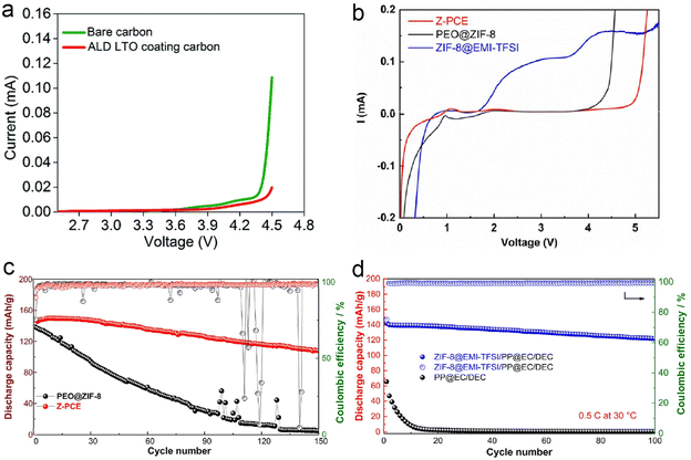 | ||
| Fig. 22 (a) Comparison of the linear sweep voltammogram of the Li/SPE/PEO-carbon composite cell and Li/SPE/PEO-LTO@carbon composite cell (scan rate = 0.3 mV s−1, from OCV to 4.5 V vs. Li/Li+). Reproduced with permission from ref. 151. Copyright 2020, Royal Society of Chemistry. (b) LSV of Z-PCE, ZIF-8@EMI-TFSI, and PEO@ZIF-8 at 60 °C. (c) Cycle performance of PEO@ZIF-8 and Z-PCE half cells at 0.2C under 60 °C. (d) Cycle performance of PEO@ZIF-8 and Z-PCE half cells at 0.5C under 30 °C. Reproduced with permission from ref. 155. Copyright 2022, Elsevier. | ||
5.2. High loading capacity
Although the ASSLIBs are regarded as one of the most promising options in the future electrochemical energy storage devices, their development is still limited by their low positive load and poor rate performance. Hu et al. developed a novel in situ polymerized integrated ultrathin PVC/SN-LLZTO SSE, which not only acts as a rigid scaffold to prevent direct contact between the cathode and the anode but also as an active inorganic filler to enhance the mechanical properties of in situ polymerized SSE film.149 In order to demonstrate the effects of the integrated ultrathin PVC/SN-LLZTO SSE under practical working conditions, they fabricated the Li||NCM811 full cells with an increased NCM811 loading of 8.3 mg cm−2. The cell with the PVC/SN-LLZTO SSE delivers a high initial discharge capacity of 190.7 mA h g−1 and achieves 73.4% capacity retention after 100 cycles at 0.1C (Fig. 23a). Considering the practical application potential of integrated ultrathin electrolyte/electrode structure design coupled with in situ polymerization, the pouch cells with ultrathin Li metal anodes (33 μm) and a high-loading NCM811 cathode (20.6 mg cm−2) were prepared (Fig. 23b). The pouch cell can stably cycle and exhibits a high initial discharge capacity of 93 mA h (Fig. 23c). Moreover, the pouch cells with rationally designed LiF-rich SEI can cycle for >35 cycles. Furthermore, the pouch cells were subjected to a series of flexibility and safety tests. As shown in Fig. 23d, the solid-state pouch cell operates well to light up a red light-emitting diode bulb. Even under destructive conditions such as being folded and cut, the cells still exhibit reliability and high safety. For practical evaluation, the pouch cells are assembled based on the ultrathin fire-proof framework (UFF)/PEO/PAN/LiTFSI, thin Li foil, and high-loading NCM811 cathodes (13 mg cm−2) with an area of 22 cm2, which exhibit a reversible capacity of 174 mA h g−1 (Fig. 23e). The pouch cell can easily power a light-emitting diode after charging to upper cut-off voltage. And bending the cell would not turn down the diode. Though the light shimmers after four-successive cuts to the pouch cell due to the loose electrode–electrolyte contact, the pouch cell shows safe performance under severe conditions (Fig. 23f).157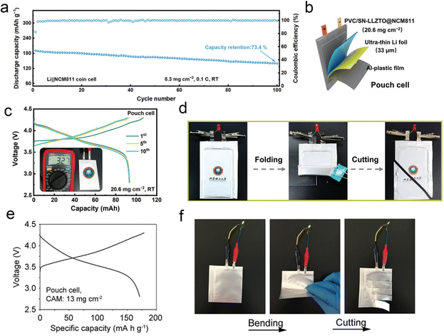 | ||
| Fig. 23 (a) Cycling stability and the corresponding coulombic efficiencies of Li||NCM811 full cells with a cathode loading of 8.3 mg cm−2 at 0.1C and RT. (b) Schematic diagram of the pouch cell composed of the integrated PVC/SN-LLZTO@NCM811 and ultrathin Li foil. (c) Charge and discharge voltage profiles of the Li||NCM811 pouch cell with a NCM811 loading of 20.6 mg cm−2 at 0.05C. (d) The optical photograph of the pouch cell lighting a diode before and after folding and cutting tests. Reproduced with permission from ref. 149. Copyright 2024, Wiley-VCH Gmbh. (e) The charge/discharge voltage profiles at the second cycle of the Li|UFF/PEO/PAN/LiTFSI|NCM811 pouch cell with a cathode active material (CAM) loading of 13 mg cm−2 at 0.45 mA cm−2 and (f) the optical photograph of the pouch cell powering a light-emitting diode under normal, bending, and cutting state. Reproduced with permission from ref. 157. Copyright 2021, Wiley-VCH Gmbh. | ||
5.3. Wide temperature range
For wide temperature applications, polymer-based batteries are bound to face more complex performance requirements, including not only the performance of the electrolyte itself, but also the stability of the electrode–electrolyte interface. Low-temperature environments significantly reduce the ionic conductivity of polymers, as the Li+ transport rate decreases exponentially with temperature, leading to larger energy barriers for electrochemical reactions and severe cell polarization. Low temperatures ultimately lead to a decrease in the ionic conductivity of the polymer and a decrease in the capacity of the polymer battery, even to the point of not being able to charge and discharge properly. Polymers exhibit high ionic conductivity at high temperatures. However, the attendant difficulty is that the polymer tends to soften severely, shrink, and even decompose. Such events typically lead to battery failure or catastrophic events. Therefore, the application of polymers at elevated temperatures has focused on improving their high temperature stability and non-flammability. At elevated temperatures, the mechanical properties of polymer electrolytes deteriorate, reducing the ability to inhibit lithium dendrites and affecting performance and safety.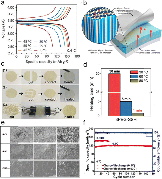 | ||
| Fig. 24 (a) Voltage profiles of the LiFePO4–Li cells at various temperatures from 15 to 65 °C. Reproduced with permission from ref. 162. Copyright 2018, Wiley-VCH Gmbh. (b) Schematic of a multiscale aligned mesoporous garnet LLZO membrane incorporated with a polymer electrolyte in a lithium symmetric cell. Reproduced with permission from ref. 168. Copyright 2019, American Chemical Society. (c) Photographs of disk-shaped 3PEG-SSH cut into different forms. (d) Self-healing time of 3PEG-SSH. Reproduced with permission from ref. 163. Copyright 2020, American Chemical Society. (e) The SEM images of Li anodes using different electrolytes after 500 h Li//Li cycles. Reproduced with permission from ref. 164. Copyright 2020, Elsevier. (f) Galvanostatic cycling performances of Li|Homo-SPE|LiFePO4 cells at 0 °C. Reproduced with permission from ref. 165. Copyright 2020, Wiley-VCH Gmbh. | ||
5.4. Low external pressure
While solid-state electrolytes have received a lot of attention due to their high energy density and high safety, the external pressure during the operation of solid-state batteries has also received the attention of researchers. At present, the operation of solid-state batteries requires tens or even hundreds of megapascals of pressure to ensure the contact between the solid-state electrode and the electrolyte interface, which greatly increases the cost of solid-state batteries and hinders the practical application of solid-state batteries. To solve the problem, Pan et al.166 designed an elastic electrolyte based on a mixture of a dual monomer copolymer and a deep eutectic solvent, applying it to solid-state batteries to achieve stable operation without any external pressure, relying only on the internal pressure of the battery. In order to measure the internal pressure, they developed a thin-film pressure-sensitive sensor (Fig. 25a), which measured the internal pressures of the button battery and the soft pack battery of 546 kPa and 52 kPa, respectively (Fig. 25b). These pressures are significantly lower than the conventional external pressure applied to solid-state batteries. The LiFePO4||Li battery has a reversible specific capacity of 147.4 mA h g−1, and can be stable for 400 cycles (Fig. 25c). The LiFePO4||μm-Si full battery can cycle for 150 cycles (Fig. 25d), and the soft-pack battery can still work under the shearing and bending conditions (Fig. 25e). Besides, under the guidance of “micro-viscosity control”, Wang's team167 made full use of the strong adsorption between polymer chains and ions to effectively regulate the condensed state structure of polymer electrolytes, successfully constructing a high-entropy polymer tape electrolyte (HETE) (Fig. 25f). By using the excellent surface adhesion characteristics of HETE, the in situ interface bonding between the electrolyte film and the electrode was realized. After simple pressing and packaging, a flexible solid-state tape battery that can work without external pressure can be obtained. The electrochemical performance of the Li|HETE|LFP tape battery was also evaluated and Fig. 25g shows the stable cycling performance at 0.1C at 50 °C over 20 cycles. The solid-state tape battery has excellent interface stability and flexibility, maintaining interface stability without additional pressure, and can withstand extreme deformation such as distortion and compression.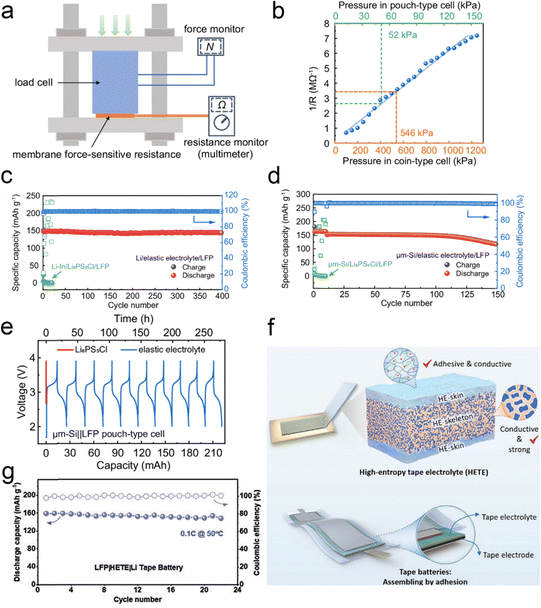 | ||
| Fig. 25 (a) Schematic of calibration of the membrane force-sensitive resistance (MFSR). (b) The fitted standard response curve (blue) of resistance to pressure of the MFSR. The built-in pressure of the coin-type and pouch-type cell is indicated with the orange and green dashed line, respectively. Electrochemical performance of SSBs using elastic electrolytes at zero applied pressure and relying only on the battery's built-in stress. Long cycle stability of the (c) LFP||μm-Si full battery and (d) LFP||Li battery. (e) LFP||μm-Si soft pack battery's charge and discharge curve. Reproduced with permission from ref. 166. Copyright 2024, Spring Nature. (f) The schematic of high-entropy tape electrolyte (HETE) and compression-free solid-state tape batteries. (g) Cycle performance of the LFP||Li tape batteries with HETE electrolytes at 50 °C. Reproduced with permission from ref. 167. Copyright 2023, Wiley-VCH Gmbh. | ||
6. Summary and outlook
Solid-state electrolytes have gradually become a hot spot for the development of the electric vehicle industry in recent years due to their high safety. Among these, polymer electrolytes have received wide attention for their simple preparation, flexibility, and better contact with electrodes. Therefore, this review introduces the ion transport mechanism of solid electrolytes, summarizes the advanced strategies for improving the ionic conductivity of polymer–inorganic solid electrolytes, and discusses the construction of the electrode/electrolyte interface, systematically analyzing the electrochemical properties of polymer electrolytes. In general, polymer–inorganic solid electrolytes have become the current development hotspot of all-solid polymer-based lithium batteries; however, they still face many difficulties, such as low ionic conductivity, a narrow electrochemical window, interface instability, and so on, which seriously limit their commercial development. In future research, realizing the high-performance application of polymer-based solid-state batteries is still a big challenge. Fig. 26 summarizes the approaches to achieving high performance in solid-state batteries from the following aspects and provides the elements of battery performance evaluation.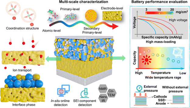 | ||
| Fig. 26 The diagram of methods for achieving high performance of SSBs and factors for evaluating battery performance. | ||
(1) Li+ coordination structure
The solvation structure is derived from the competitive coordination of solvents and anions with Li+ and is determined by many factors. The polarity of the components is one of the factors that affect their coordination with Li+. Selecting suitable ligands, controlling the solvent environment, adjusting temperature and pressure, using auxiliary ligands and employing biomimetic design can improve the coordination structure, stability and function of lithium ions.(2) Ion transport
Investigating the mechanisms by which the coordination structure affects ion transport and optimizing solvent–polymer–ion interactions in polymer electrolytes are essential. The design of SPEs that “decouples” the Li+ movement and the segmented movement of the polymer not only can maintain the mechanical strength of the SPEs but also can promote ion transmission.(3) Interface engineering
Regulating the interaction between the electrolyte and the electrode through interface engineering, optimizing the interface film-forming behavior, and improving the cycling stability and safety of batteries are crucial. Future development will have to focus on the design of polymer electrolytes with excellent interface stability to achieve the commercial application of high-performance lithium-ion batteries. The interface film-forming properties of electrolytes are improved by surface modification, interface modulation and interface design. These methods can help reduce the interface impedance between the electrolyte and the electrode, thereby improving the cycle life and safety of the battery.(4) Multi-scale characterization
In solid electrolytes, ion migration is a multi-scale process, involving multiple scales from atoms to electrodes. The detection of ion transport at different scales requires a combination of various characterization techniques to achieve effective observation. In situ online characterization techniques are very important for real-time monitoring of the reaction process in the working state of the battery, which is helpful for researchers to analyze the reaction mechanism. In addition, a series of advanced characterization methods, such as NMR, nano-IR, and cryo-TEM, are also crucial for studying the surface interface and chemical processes of solid-state batteries.In general, the current development of polymer–inorganic SSEs is a booming field for sustainable energy-related materials and devices, and SSBs have a wide range of application prospects in new energy vehicles. Future research on SSEs can evaluate the electrochemical performance of SSBs by using parameters related to high voltage cathode, high mass loading, wide temperature range, and low external pressure, thereby providing good safety, higher energy density, and longer cycle life.
Author contributions
Qingqing Zhou: writing – original draft, investigation, formal analysis. Minfeng Chen: software. Junjie Lu: conceptualization. Bifu Sheng: investigation. Jizhang Chen: supervision. Qiaobao Zhang: supervision. Xiang Han: writing – review & editing, supervision, project administration, funding acquisition.Data availability
Data availability is not applicable to this article as no new data were created or analyzed in this study.Conflicts of interest
The authors declare that they have no conflicts of interest.Acknowledgements
This work was financially supported by the National Natural Science Foundation of China (22209075, 92472104, 52122211) and the Shenzhen Technical Plan Project (No. JCYJ20220818101003008).References
- M. Wakihara, Mater. Sci. Eng., R, 2001, 33, 109–134 CrossRef.
- S. B. Ge, K. X. Wei, W. X. Peng, R. Z. Huang, E. Akinlabi, H. Y. Xia, M. W. Shahzad, X. H. Zhang, B. B. Xu and J. C. Jiang, Chem. Soc. Rev., 2024, 23, 11259–11302 RSC.
- K. Xu, Chem. Rev., 2004, 104, 4303–4418 CrossRef CAS PubMed.
- J. X. Liu, S. Ihuaenyi, R. Kuphal, J. Salinas, L. Xie, L. Yang, U. Janakiraman, M. E. Fortier and C. C. Fang, J. Electrochem. Soc., 2023, 170, 010535 CrossRef CAS.
- D. X. Ouyang, K. Wang, Y. M. Pang and Z. R. Wang, ACS Appl. Energy Mater., 2023, 6, 2063–2071 CrossRef CAS.
- C. C. Su, M. N. He, J. Y. Shi, R. Amine, Z. Yu, L. Cheng, J. C. Guo and K. Amine, Energy Environ. Sci., 2021, 14, 3029–3034 Search PubMed.
- J. Liu, Z. N. Bao, Y. Cui, E. J. Dufek, J. B. Goodenough, P. Khalifah, Q. Y. Li, B. Y. Liaw, P. Liu, A. Manthiram, Y. S. Meng, V. R. Subramanian, M. F. Toney, V. V. Viswanathan, M. S. Whittingham, J. Xiao, W. Xu, J. H. Yang, X. Q. Yang and J. G. Zhang, Nat. Energy, 2019, 4, 180–186 Search PubMed.
- T. Famprikis, P. Canepa, J. A. Dawson, M. S. Islam and C. Masquelier, Nat. Mater., 2019, 18, 1278–1291 CrossRef CAS PubMed.
- Q. Zhao, S. Stalin, C. Z. Zhao and L. A. Archer, Nat. Rev. Mater., 2020, 5, 229–252 CrossRef CAS.
- A. Manthiram, X. W. Yu and S. F. Wang, Nat. Rev. Mater., 2017, 2, 16103 CrossRef CAS.
- J. B. Goodenough, H. P. Hong and J. Kafalas, Mater. Res. Bull., 1976, 11, 203–220 CrossRef CAS.
- H. Y. P. Hong, Mater. Res. Bull., 1978, 13, 117–124 CrossRef CAS.
- J. Fu, Solid State Ionics, 1997, 104, 191–194 CrossRef CAS.
- J. Fu, Solid State Ionics, 1997, 96, 195–200 Search PubMed.
- Y. Inaguma, C. Liquan, M. Itoh, T. Nakamura, T. Uchida, H. Ikuta and M. Wakihara, Solid State Commun., 1993, 86, 689–693 Search PubMed.
- R. Murugan, V. Thangadurai and W. Weppner, Angew. Chem., Int. Ed., 2007, 46, 7778–7781 CrossRef CAS PubMed.
- R. Koerver, I. Aygün, T. Leichtweiß, C. Dietrich, W. Zhang, J. O. Binder, P. Hartmann, W. G. Zeier and J. Janek, Chem. Mater., 2017, 29, 5574–5582 CrossRef CAS.
- X. G. Han, Y. H. Gong, K. Fu, X. F. He, G. T. Hitz, J. Q. Dai, A. Pearse, B. Y. Liu, H. Wang, G. Rubloff, Y. F. Mo, V. Thangadurai, E. D. Wachsman and L. B. Hu, Nat. Mater., 2017, 16, 572–579 CrossRef CAS PubMed.
- H. J. Deiseroth, S. T. Kong, H. Eckert, J. Vannahme, C. Reiner, T. Zaiß and M. Schlosser, Angew. Chem., Int. Ed., 2008, 47, 755–758 CrossRef CAS PubMed.
- N. Kamaya, K. Homma, Y. Yamakawa, M. Hirayama, R. Kanno, M. Yonemura, T. Kamiyama, Y. Kato, S. Hama, K. Kawamoto and A. Mitsui, Nat. Mater., 2011, 10, 682–686 CrossRef CAS PubMed.
- Y. Seino, T. Ota, K. Takada, A. Hayashi and M. Tatsumisago, Energy Environ. Sci., 2014, 7, 627–631 RSC.
- Y. Kato, S. Hori, T. Saito, K. Suzuki, M. Hirayama, A. Mitsui, M. Yonemura, H. Iba and R. Kanno, Nat. Energy, 2016, 1, 16030 CrossRef CAS.
- M. A. Kraft, S. P. Culver, M. Calderon, F. Bocher, T. Krauskopf, A. Senyshyn, C. Dietrich, A. Zevalkink, J. Janek and W. G. Zeier, J. Am. Chem. Soc., 2017, 139, 10909–10918 CrossRef CAS PubMed.
- J. Lee, T. Lee, K. Char, K. J. Kim and J. W. Choi, Acc. Chem. Res., 2021, 54, 3390 CrossRef CAS PubMed.
- H. Wang, H. An, H. Shan, L. Zhao and J. Wang, Acta Phys.-Chim. Sin., 2021, 37, 2007070 Search PubMed.
- L. L. Liu, F. Wu, H. Li and L. Q. Chen, J. Chin. Ceram. Soc., 2019, 47, 1367–1385 CAS.
- Y. K. Liu, T. Yu, S. H. Guo and H. S. Zhou, Acta Phys.-Chim. Sin., 2023, 39, 2301027 Search PubMed.
- B. He, F. Zhang, Y. Xin, C. Xu, X. Hu, X. Wu, Y. Yang and H. Tian, Nat. Rev. Chem., 2023, 7, 826–842 Search PubMed.
- W. Weppner and R. A. Huggins, Phys. Lett. A, 1976, 58, 245–248 CrossRef.
- R. Kanno, Y. Takeda and O. Yamamoto, Mater. Res. Bull., 1981, 16, 999–1005 CrossRef CAS.
- Y. Tomita, H. Matsushita, K. Kobayashi, Y. Maeda and K. Yamada, Solid State Ionics, 2008, 179, 867–870 CrossRef CAS.
- T. Asano, A. Sakai, S. Ouchi, M. Sakaida, A. Miyazaki and S. Hasegawa, Adv. Mater., 2018, 30, 1803075 CrossRef PubMed.
- X. Li, J. Liang, N. Chen, J. Luo, K. R. Adair, C. H. Wang, M. N. Banis, T. K. Sham, L. Zhang, S. Q. Zhao, S. G. Lu, H. Huang, R. Y. Li and X. L. Sun, Angew. Chem., 2019, 131, 16579–16584 CrossRef.
- Q. Zhang, K. Liu, K. Liu, L. Zhou, C. Ma and Y. Du, Electrochim. Acta, 2020, 351, 136342 CrossRef CAS.
- D. E. Fenton, Polymer, 1973, 14, 589 CrossRef CAS.
- C. Berthier, W. Gorecki, M. Minier, M. B. Armand, J. M. Chabagno and P. Riguad, Solid State Ionics, 1983, 11, 91–95 CrossRef CAS.
- K. Tsunemi, H. Ohno and E. Tsuchida, Electrochim. Acta, 1983, 28, 833–837 CrossRef CAS.
- M. Watanabe, M. Kanba, K. Nagaoka and I. Shinohara, J. Polym. Sci., Polym. Phys. Ed., 1983, 21, 939–948 CrossRef CAS.
- M. Alamgir, R. D. Moulton and K. M. Abraham, Electrochim. Acta, 1991, 36, 773–782 CrossRef CAS.
- X. Y. Wei and D. F. Shriver, Chem. Mater., 1998, 10, 2307–2308 CrossRef CAS.
- J. Wu, S. Liu, F. Han, X. Yao and C. Wang, Adv. Mater., 2021, 33, 2000751 CrossRef CAS PubMed.
- Z. Liu, W. Fu, E. A. Payzant, X. Yu, Z. Wu, N. J. Dudney, J. Kiggans, K. Hong and A. J. Rondinone, J. Am. Chem. Soc., 2013, 135, 975–978 CrossRef CAS PubMed.
- H. Tsukasaki, S. Mori, H. Morimoto, A. Hayashi and M. Tatsumisago, Sci. Rep., 2017, 7, 4142 CrossRef PubMed.
- S. Breuer, M. Uitz and H. M. R. Wilkening, J. Phys. Chem. Lett., 2018, 9, 2093–2097 CrossRef CAS PubMed.
- J. F. Wu and X. Guo, Phys. Chem. Chem. Phys., 2017, 19, 5880–5887 RSC.
- J. A. Dawson, P. Canepa, T. Famprikis, C. Masquelier and M. S. Islam, J. Am. Chem. Soc., 2018, 140, 362–368 CrossRef CAS PubMed.
- A. Sakuda, A. Hayashi and M. Tatsumisago, Chem. Mater., 2010, 22, 949–956 CrossRef CAS.
- C. Yu, S. Ganapathy, E. R. H. Eck, H. Wang, S. Basak, Z. Li and M. Wagemaker, Nat. Commun., 2017, 8, 1086 CrossRef PubMed.
- D. Lu, R. Li, M. M. Rahman, P. Yu, L. Lv, S. Yang, Y. Huang, C. Sun, S. Zhang, H. Zhang and J. Zhang, Nature, 2024, 627, 101–107 CrossRef CAS PubMed.
- L. Yue, J. Ma, J. Zhang, J. Zhao, S. Dong, Z. Liu, G. Cui and L. Chen, Energy Storage Mater., 2016, 5, 139–164 CrossRef.
- A. S. Shaplov, R. Marcilla and D. Mecerreyes, Electrochim. Acta, 2015, 175, 18–34 CrossRef CAS.
- K. S. Ngai, S. Ramesh, K. Ramesh and J. C. Juan, Ionics, 2016, 22, 1259–1279 CrossRef CAS.
- X. Lu, Y. Wang, X. Xu, B. Yan, T. Wu and L. Lu, Adv. Energy Mater., 2023, 13, 2301746 CrossRef CAS.
- L. Z. Fan, H. C. He and C. W. Nan, Nat. Rev. Mater., 2021, 6, 1003–1019 CrossRef CAS.
- F. Wu, Z. Wen, Z. Zhao, J. Bi, Y. Shang, Y. Liang, L. Li, N. Chen, Y. Li and R. Chen, Energy Storage Mater., 2021, 38, 447–453 CrossRef.
- D. Lin, W. Liu, Y. Liu, H. R. Lee, P. C. Hsu, K. Liu and Y. Cui, Nano Lett., 2016, 16, 459–465 CrossRef CAS PubMed.
- G. X. Wang, L. Yang, J. Z. Wang, H. K. Liu and S. X. Dou, J. Nanosci. Nanotechnol., 2005, 5, 1135–1140 CrossRef CAS PubMed.
- C. Hu, Y. Shen, M. Shen, X. Liu, H. Chen, C. Liu, T. Kang, F. Jin, L. Li, J. Li, Y. Li, N. Zhao and X. Guo, J. Am. Chem. Soc., 2020, 142, 18035–18041 CrossRef CAS PubMed.
- H. Gao, N. S. Grundish, Y. Zhao, A. Zhou and J. B. Goodenough, Energy Mater. Adv., 2021, 1932952 CAS.
- Y. W. Chen-Yang, H. C. Chen, F. J. Lin and C. C. Chen, Solid State Ionics, 2002, 150, 327–335 CrossRef CAS.
- W. Liu, S. W. Lee, D. Lin, F. Shi, S. Wang, A. D. Sendek and Y. Cui, Nat. Energy, 2017, 2, 1–7 Search PubMed.
- Z. Li, H. M. Huang, J. K. Zhu, J. F. Wu, H. Yang, L. Wei and X. Guo, ACS Appl. Mater. Interfaces, 2018, 11, 784–791 CrossRef PubMed.
- S. S. Chi, Y. Liu, N. Zhao, X. Guo, C. W. Nan and L. Z. Fan, Energy Storage Mater., 2019, 17, 309–316 CrossRef.
- C. Wang, Y. Yang, X. Liu, H. Zhong, H. Xu, Z. Xu, H. Shao and F. Ding, ACS Appl. Mater. Interfaces, 2017, 9, 13694–13702 CrossRef CAS PubMed.
- J. Li, K. Zhu, Z. Yao, G. Qian, J. Zhang, K. Yan and J. Wang, Ionics, 2020, 26, 1101–1108 CrossRef CAS.
- P. Shi, J. Ma, M. Liu, S. Guo, Y. Huang, S. Wang, L. Zhang, L. Chen, K. Yang, X. Liu, Y. Li and X. An, Nat. Nanotechnol., 2023, 1–9 Search PubMed.
- Q. Wu, M. Fang, S. Jiao, S. Li, S. Zhang and Z. Shen, Nat. Commun., 2023, 14, 6296 CrossRef CAS PubMed.
- P. Yadav, M. S. Hosen, P. K. Dammala, P. Ivanchenko, J. V. Mierlo and M. Berecibar, Solid State Ionics, 2023, 399, 116308 CrossRef CAS.
- H. Yang, B. Zhang, M. X. Jing, X. Q. Shen, L. Wang, H. Xu, X. H. Yan and X. M. He, Adv. Energy Mater., 2022, 12, 2201762 CrossRef CAS.
- K. X. Mu, D. Wang, W. L. Dong, Q. Liu, Z. N. Song, W. J. Xu, P. P. Yao, Y. A. Chen, B. Yang, C. H. Li, L. Tian, C. Z. Zhu and J. Xu, Adv. Mater., 2023, 35, 2304686 CrossRef CAS PubMed.
- Z. H. Ren, J. X. Li, M. H. Cai, R. N. Yin, J. N. Liang, Q. L. Zhang, C. X. He, X. T. Jiang and X. Z. Ren, J. Mater. Chem. A, 2023, 11, 1966–1977 RSC.
- S. Q. Huang, Z. L. Cui, L. X. Qiao, G. J. Xu, J. J. Zhang, K. Tang, X. C. Liu, Q. L. Wang, X. H. Zhou, B. T. Zhang and G. L. Cui, Electrochim. Acta, 2019, 299, 820–827 CrossRef CAS.
- K. Yang, L. K. Chen, J. B. Ma, C. Lai, Y. F. Huang, J. S. Mi, J. Biao, D. F. Zhang, P. R. Shi, H. Y. Xia, G. M. Zhong, F. Y. Kang and Y. B. He, Angew. Chem., Int. Ed., 2021, 60, 24668–24675 CrossRef CAS PubMed.
- W. W. Li, C. Z. Sun, J. Jin, Y. P. Li, C. H. Chen and Z. Y. Wen, J. Mater. Chem. A, 2019, 7, 27304–27312 RSC.
- H. T. Zhang, Y. C. Wang, J. F. Huang, W. Li, X. K. Zeng, A. L. Jia, H. Z. Peng, X. Zhang and W. Q. Yang, Energy Environ. Mater., 2024, 7, e12514 CrossRef CAS.
- B. Tong, Z. Song, H. Wu, X. Wang, W. Feng, Z. Zhou and H. Zhang, Mater. Futures, 2022, 1, 042103 CrossRef CAS.
- M. Armand, J. M. Chabagno and M. J. Duclot, Fast Ion Transp. Solids:Electrodes Electrolytes, Proc. Int. Conf., 1979, 131–136 CAS.
- Z. Stoeva, I. Martin-Litas, E. Staunton, Y. G. Andreev and P. G. Bruce, J. Am. Chem. Soc., 2003, 125, 4619–4626 CrossRef CAS PubMed.
- C. Zhang, Y. G. Andreev and P. G. Bruce, Angew. Chem., Int. Ed., 2007, 46, 2848–2850 CrossRef CAS PubMed.
- C. Zhang, S. Gamble, D. Ainsworth, A. M. Z. Slawin, Y. G. Andreev and P. G. Bruce, Nat. Mater., 2009, 8, 580–584 CrossRef CAS PubMed.
- C. A. Angell, J. Fan, C. Liu, Q. Lu, E. Sanchez and K. Xu, Solid State Ionics, 1994, 69, 343–353 CrossRef CAS.
- C. A. Angell, C. Liu and E. Sanchez, Nature, 1993, 362, 137–139 CrossRef CAS.
- Y. Takahashi and H. Tadokoro, Macromolecules, 1973, 6, 672–675 CrossRef CAS.
- P. Johansson, Polymer, 2001, 42, 4367–4373 CrossRef CAS.
- C. D. Robitaille and D. J. Fauteux, Electrochem. Soc., 1986, 133, 315 CrossRef CAS.
- D. G. H. Ballard, P. Cheshire, T. S. Mann and J. E. Przeworski, Macromolecules, 1990, 23, 1256–1264 CrossRef CAS.
- G. Orädd, L. Edman and A. Ferry, Solid State Ionics, 2002, 152, 131–136 CrossRef.
- G. Zardalidis, E. Ioannou, S. Pispas and G. Floudas, Macromolecules, 2013, 46, 2705–2714 CrossRef CAS.
- H. Jiang, Q. Zhang, Y. Zhang, L. Sui, G. Wu, K. Yuan and X. Yang, Phys. Chem. Chem. Phys., 2019, 21, 10417–10422 RSC.
- S. Han, Sci. Rep., 2019, 9, 1–10 CrossRef PubMed.
- J. Zheng and Y. Y. Hu, ACS Appl. Mater. Interfaces, 2018, 10, 4113–4120 CrossRef CAS PubMed.
- H. Lee, M. Yanilmaz, O. Toprakci, K. Fu and X. Zhang, Energy Environ. Sci., 2014, 7, 3857–3886 RSC.
- D. Zhang, Y. Liu, S. Yang, J. Zhu, H. Hong, S. Li, Q. Xiong, Z. Huang, S. Wang, J. Liu and C. Zhi, Adv. Mater., 2024, 2401549 CrossRef CAS PubMed.
- S. A. Pervez, G. Kim, B. P. Vinayan, M. A. Cambaz, M. Kuenzel, M. Hekmatfar and M. Fichtner, Small, 2020, 16, 2000279 CrossRef CAS PubMed.
- Q. Zhang, K. Liu, K. Liu, J. Li, C. Ma, L. Zhou and Y. Du, J. Colloid Interface Sci., 2020, 580, 389–398 CrossRef CAS PubMed.
- J. Zagorski, J. M. Lopez del Amo, M. J. Cordill, F. Aguesse and L. Buannic, ACS Appl. Energy Mater., 2019, 2, 1734–1746 CrossRef CAS.
- J. G. Connell, T. Fuchs, H. Hartmann, T. Krauskopf, Y. S. Zhu, J. Sann, R. Garcia-Mendez, J. Sakamoto, S. Tepavcevic and J. Janek, Chem. Mater., 2020, 32, 10207–10215 CrossRef CAS.
- T. Jiang, P. He, G. Wang, Y. Shen, C. W. Nan and L. Z. Fan, Adv. Energy Mater., 2020, 10, 1903376 CrossRef CAS.
- H. Yamada, D. Tsunoe, S. Shiraishi and G. Isomichi, J. Phys. Chem. C, 2015, 119, 5412–5419 CrossRef CAS.
- M. Agostini, Y. Aihara and T. Yamada, J. Electrochem. Soc., 2013, 244, 48–51 CAS.
- Q. Zhang, Y. Q. Kong, K. X. Gao, Y. J. Wen, Q. Zhang, H. Y. Fang, C. J. Ma and Y. P. Du, Sci. China: Technol. Sci., 2022, 65, 2246–2258 CrossRef CAS.
- B. Jiang, J. Iocozzia, L. Zhao, H. F. Zhang, Y. W. Harn, Y. H. Chen and Z. Q. Lin, Chem. Soc. Rev., 2019, 48, 1194–1228 RSC.
- Y. P. Guo, R. Y. Wang, C. Cui, R. D. Xiong, Y. Q. Wei, T. Y. Zhai and H. Q. Li, Nano Lett., 2020, 20, 7680–7687 CrossRef CAS PubMed.
- K. Takada, N. Ohta, L. Q. Zhang, X. X. Xu, B. T. Hang, T. Ohnishi, M. Osada and T. Sasaki, Solid State Ionics, 2012, 225, 594–597 CrossRef CAS.
- B. B. Wu, S. Y. Wang, W. J. Evans IV, D. Z. Deng, J. H. Yang and J. Xiao, J. Mater. Chem. A, 2016, 4, 15266–15280 RSC.
- C. Yada, C. E. Lee, D. Laughman, L. Hannah, H. Iba and B. E. Hayden, J. Electrochem. Soc., 2015, 162, A722–A726 CrossRef CAS.
- S. H. Xia, Y. Zhao, J. H. Yan, J. Y. Yu and B. Ding, ACS Nano, 2021, 15, 3161–3170 CrossRef CAS PubMed.
- H. Yamada, A. J. Bhattacharyya and J. Maier, Adv. Funct. Mater., 2006, 16, 525–530 CrossRef CAS.
- L. Pan, S. Sun, G. Yu, X. X. Liu, S. Feng, W. Zhang, M. Turgunov, Y. Wang and Z. M. Sun, Chem. Eng. J., 2022, 449, 137682 CrossRef CAS.
- W. Zhang, V. Koverga, S. Liu, J. Zhou, J. Wang, P. Bai, S. Tan, N. K. Dandu, Z. Wang, F. Chen, J. Xia, H. L. Wan, X. Y. Zhang, H. C. Yang, B. L. Lucht, A. M. Li, X. Q. Yang, E. Y. Hu, S. R. Raghavan, A. T. Ngo and C. S. Wang, Nat. Energy, 2024, 9, 386–400 CrossRef CAS.
- S. M. Wu, Lanzhou University of Technology, 2020.
- P. Yao, B. Zhu, H. Zhai, X. Liao, Y. Zhu, W. Xu, Q. Cheng, C. Jayyosi, Z. Li, J. Zhu, K. M. Myers, X. Chen and Y. Yang, Nano Lett., 2018, 18, 6113–6120 CrossRef CAS PubMed.
- M. M. Heravi, M. Ghavidel and L. Mohammadkhani, RSC. Adv., 2018, 8, 27832 RSC.
- J. Lang, Y. Long, J. Qu, X. Luo, H. Wei, K. Huang, H. Zhang, L. Qi, Q. Zhang, Z. Li and H. Wu, Energy Storage Mater., 2019, 16, 85–90 CrossRef.
- X. Zhang, J. Han, X. Niu, C. Xin, C. Xue, S. Wang, Y. Shen, L. Zhang, L. Li and C. W. Nan, Batteries Supercaps, 2020, 3, 876–883 CrossRef CAS.
- Y. Liu, X. An, K. Yang, J. Ma, J. Mi, D. Zhang, X. Cheng, Y. Li, Y. Ma, M. Liu, F. Kang and Y. B. He, Energy Environ. Sci., 2024, 17, 344–353 RSC.
- P. B. Zhai, Z. L. Yang, Y. Wei, X. X. Guo and Y. J. Gong, Adv. Energy Mater., 2022, 12, 2200967 CrossRef CAS.
- T. Liu, Y. Zhang, R. Chen, S. X. Zhao, Y. Lin, C. W. Nan and Y. Shen, Electrochem. Commun., 2017, 79, 1–4 CrossRef CAS.
- B. He, F. Zhang, Y. Xin, C. Xu, X. Hu, X. Wu, Y. Yang and H. Tian, Nat. Rev. Chem., 2023, 7, 826–842 Search PubMed.
- Y. Huang, B. Chen, J. Duan, F. Yang, T. Wang, Z. Wang, W. Yang, C. Hu, W. Luo and Y. Huang, Angew. Chem., 2020, 132, 3728–3733 CrossRef.
- K. Nie, Y. Hong, J. Qiu, Q. Li, X. Yu, H. Li and L. Chen, Front. Chem., 2018, 6, 616 CrossRef CAS PubMed.
- D. Lu, Y. F. Chen, W. W. Sun, W. Xie, S. Y. Yi, S. Q. Luo, L. L. Zuo, Y. S. Zhao, T. Y. Yang, P. T. Xiao and C. M. Zheng, Adv. Energy Mater., 2023, 13, 2301765 CrossRef.
- S. K. Heiskanen, J. Kim and B. L. Lucht, Joule, 2019, 3, 2322–2333 CrossRef CAS.
- Z. Zhang, K. Smith, R. Jervis, P. R. Shearing, T. S. Miller and D. J. L. Brett, ACS Appl. Mater. Interfaces, 2020, 12, 35132–35141 CrossRef CAS PubMed.
- J. Xu, Y. Dou, Z. Wei, J. Ma, Y. Deng, Y. Li, H. Liu and S. Dou, Adv. Sci., 2017, 4, 1700146 CrossRef PubMed.
- L. Xing, X. Zheng, M. Schroeder, J. Alvarado, A. W. Cresce, K. Xu, Q. Li and W. Li, Acc. Chem. Res., 2018, 51, 282–289 CrossRef CAS PubMed.
- Y. X. Yao, N. Yao, X. R. Zhou, Z. H. Li, X. Y. Yue, C. Yan and Q. Zhang, Adv. Mater., 2022, 34, 2206448 CrossRef CAS PubMed.
- X. Fan and C. Wang, Chem. Soc. Rev., 2021, 50, 10486–10566 RSC.
- Z. Zhang, T. Yao, E. Wang, B. Sun, K. Sun and Z. Peng, ACS Appl. Mater. Interfaces, 2022, 14, 45484–45493 CrossRef CAS PubMed.
- K. An, A. H. T. Tran, S. Kwak, J. Han and S. W. Song, Adv. Funct. Mater., 2021, 31, 2106102 CrossRef CAS.
- H. Kim, K. Lim, G. Yoon, J. H. Park, K. Ku, H. D. Lim, Y. E. Sung and K. Kang, Adv. Energy Mater., 2017, 7, 1700418 CrossRef.
- J. Y. Liang, Y. Zhang, S. Xin, S. J. Tan, X. H. Meng, W. P. Wang, J. L. Shi, Z. B. Wang, F. Wang, L. J. Wan and G. Y. Guo, Angew. Chem., Int. Ed., 2023, 62, e202300384 CrossRef CAS PubMed.
- J. M. Tarascon and M. Armand, Nature, 2001, 414, 359–367 CrossRef CAS PubMed.
- R. Wang, W. Cui, F. Chu and F. Wu, J. Energy Chem., 2020, 48, 145–159 CrossRef.
- M. Li, H. An, Y. Song, Q. Liu, J. Wang, H. Huo, S. Lou and J. Wang, J. Am. Chem. Soc., 2023, 145, 25632–25642 CrossRef CAS PubMed.
- Z. Li, R. Yu, S. Weng, Q. Zhang, X. Wang and X. Guo, Nat. Commun., 2023, 14, 482 CrossRef PubMed.
- M. N. Obrovac, L. Christensen, D. B. Le and J. R. Dahn, J. Electrochem. Soc., 2007, 154, 849 CrossRef.
- C. Wang, C. Yang and Z. Zheng, Adv. Sci., 2022, 9, 2105213 CrossRef CAS PubMed.
- M. Zhao, J. Zhang, C. M. Costa, S. Lanceros-Méndez, Q. Zhang and W. Wang, Adv. Mater., 2024, 36, 2308590 CrossRef CAS PubMed.
- R. Endo, T. Ohnishi, K. Takada and T. Masuda, J. Phys. Chem. Lett., 2020, 11, 6649–6654 CrossRef CAS PubMed.
- L. H. Gu, J. J. Han, M. F. Chen, W. J. Zhou, X. F. Wang, M. Xu, H. C. Lin, H. D. Liu, H. X. Chen, J. Z. Chen, Q. B. Zhang and X. Han, Energy Storage Mater., 2022, 52, 547–561 CrossRef.
- X. Han, L. H. Gu, Z. F. Sun, M. F. Chen, Y. G. Zhang, L. S. Luo, M. Xu, S. Y. Chen, H. D. Liu, J. Y. Wan, Y. B. He and J. Chen, Energy Environ. Sci., 2023, 16, 5395–5408 RSC.
- Z. Zhang, Z. Sun, X. Han, Y. Liu, S. Pei, Y. Li, L. Luo, P. Su, C. Lan, Z. Zhang, S. Xu and S. Guo, Energy Environ. Sci., 2024, 17, 1061–1072 RSC.
- Y. G. Lee, S. Fujiki, C. Jung, N. Suzuki, N. Yashiro, R. Omoda, D. S. Ko, T. Shiratsuchi, T. Sugimoto, S. Ryu, J. H. Ku, T. Watanabe, Y. Park, Y. Aihara, D. Im and I. T. Han, Nat. Energy, 2020, 5, 299–308 CrossRef CAS.
- B. H. Wang, T. Xia, Q. Chen and Y. F. Yao, Polymers, 2020, 12, 391 CrossRef CAS PubMed.
- X. Lei, J. Zhao, J. Wang and D. Su, Sci. China:Chem., 2024, 67, 291–311 CrossRef CAS.
- R. Lin, Y. He, C. Wang, P. Zou, E. Hu, X. Q. Yang, K. Xu and H. L. Xin, Nat. Nanotechnol., 2022, 17, 768–776 CrossRef CAS PubMed.
- K. Chrissopoulou, K. S. Andrikopoulos, S. Fotiadou, S. Bollas, C. Karageorgaki, D. Christofilos, G. A. Voyiatzis and S. H. Anastasiadis, Macromolecules, 2011, 44, 9710–9722 CrossRef CAS.
- J. K. Hu, Y. C. Gao, S. J. Yang, X. L. Wang, X. Chen, Y. L. Liao, S. Li, J. Liu, H. Yuan and J. Q. Huang, Adv. Funct. Mater., 2024, 2311633 CrossRef CAS.
- M. Heber, K. Hofmann and C. Hess, Batteries, 2022, 8, 10 CrossRef CAS.
- J. N. Liang, Y. P. Sun, Y. Zhao, Q. Sun, J. Luo, F. P. Zhao, X. T. Lin, X. Li, R. Y. Li, L. Zhang, S. G. Lu, H. Huang and X. L. Sun, J. Mater. Chem. A, 2020, 8, 2769–2776 RSC.
- K. He, C. Chen, R. Fan, C. Liu, C. Liao, Y. Xu, J. Tang and R. K. Y. Li, Compos. Sci. Technol., 2019, 175, 28–34 CrossRef CAS.
- C. Z. Zhao, X. Q. Zhang, X. B. Cheng, R. Zhang, R. Xu, P. Y. Chen, H. J. Peng, J. Q. Huang and Q. Zhang, Proc. Natl. Acad. Sci. U. S. A., 2017, 114, 11069–11074 CrossRef CAS PubMed.
- L. Chen, Y. Li, S. P. Li, L. Z. Fan, C. W. Nan and J. B. Goodenough, Nano Energy, 2018, 46, 176–184 CrossRef CAS.
- J. Shen, Z. Lei and C. Wang, Chem. Eng. J., 2022, 447, 137503 CrossRef CAS.
- X. F. Yang, M. Jiang, X. J. Gao, D. N. Bao, Q. Sun, N. Holmes, H. Duan, S. Mukherjee, K. Adair, C. T. Zhao, J. W. Liang, W. H. Li, J. J. Li, Y. Liu, H. Huang, L. Zhang, S. G. Lu, Q. W. Lu, R. Y. Li, C. V. Singh and X. L. Sun, Energy Environ. Sci., 2020, 13, 1318–1325 RSC.
- F. He, W. Tang, X. Zhang, L. Deng and J. Luo, Adv. Mater., 2021, 33, 2105329 CrossRef CAS PubMed.
- J. Liu, K. Liang, H. Duan, G. Chen and Y. Deng, ACS Appl. Mater. Interfaces, 2023, 15, 57293–57303 CAS.
- W. Han, J. Zheng, H. Huang, H. Zhou, H. Li, H. Zhang, L. Li, W. Zhou, B. An and C. Sun, J. Membrane Sci., 2024, 123374 Search PubMed.
- R. Liao, C. Li, M. Zhou, R. Liu, S. Liu and D. Wu, Chem. Sci., 2024, 15, 18327–18334 RSC.
- J. J. Zhang, X. Zang, H. J. Wen, T. T. Dong, J. C. Chai, Y. Li, B. B. Chen, J. W. Zhao, S. M. Dong, J. Ma, L. P. Yue, Z. H. Liu, X. X. Guo, G. L. Cui and L. Q. Chen, J. Mater. Chem. A, 2017, 5, 4940–4948 RSC.
- D. Lin, P. Y. Yuen, Y. Liu, W. Liu, N. Liu, R. H. Dauskardt and Y. Cui, Adv. Mater., 2018, 30, 1802661 CrossRef PubMed.
- Y. H. Jo, S. Li, C. Zuo, Y. Zhang, H. Gan, S. Li, L. Yu, D. He, X. Xie and Z. Xue, Macromolecules, 2020, 53, 1024–1032 CrossRef CAS.
- B. Zhang, Y. Liu, X. Pan, J. Liu, K. Doyle-Davis, L. Sun, J. Liu, X. Jiao, J. Jie, H. Xie and X. Sun, Nano Energy, 2020, 72, 104690 CrossRef CAS.
- S. Xu, Z. Sun, C. Sun, F. Li, K. Chen, Z. Zhang, G. Hou, H. M. Cheng and F. Li, Adv. Funct. Mater., 2020, 30, 2007172 Search PubMed.
- H. Pan, L. Wang, Y. Shi, C. Sheng, S. Yang, P. He and H. Zhou, Nat. Commun., 2024, 15, 2263 CrossRef CAS PubMed.
- X. He, Z. Zhu, G. Wen, S. Lv, S. Yang, T. Hu, Z. Cao, Y. Ji, X. Fu, W. Yang and Y. Wang, Adv. Mater., 2024, 36, 2307599 CrossRef CAS PubMed.
- J. Q. Dai, K. Fu, Y. H. Gong, J. W. Song, C. J. Chen, Y. G. Yao, G. Pastel, L. Zhang, E. Wachsman and L. B. Hu, ACS Mater. Lett., 2019, 1, 354–361 CrossRef CAS.
| This journal is © The Royal Society of Chemistry 2025 |


