
 Open Access Article
 This Open Access Article is licensed under a
 Creative Commons Attribution 3.0 Unported Licence
Micromechanical finite element modeling of crystalline lipid-based materials: monoglyceride-based oleogels and their composites†
Patrick
Grahn
 *ab,
Petri
Lassila
ab and
Fabio
Valoppi
abcde
*ab,
Petri
Lassila
ab and
Fabio
Valoppi
abcde
aDepartment of Physics, University of Helsinki, Helsinki, Finland. E-mail: patrick.jh.grahn@helsinki.fi
bPerfat Technologies Oy, Helsinki, Finland
cDepartment of Food and Nutrition, University of Helsinki, Helsinki, Finland
dHelsinki Institute of Sustainability Science, University of Helsinki, Helsinki, Finland
eHelsinki Institute of Life Science, University of Helsinki, Helsinki, Finland
First published on 17th February 2025
Abstract
The mechanical properties of crystalline lipid-based materials are dependent on the microscale structure formed during the crystallization process. In this work, we show for the first time that the mechanical properties of such materials can be mathematically calculated by performing 3D mechanistic modeling on the exact microstructure obtained by non-destructive imaging. Initially, we obtained a digital twin of a monoglyceride-based oleogel from phase-contrast X-ray tomography. The microstructure was found to be composed of an interconnected network of crystalline platelets. Then, we applied micromechanical finite element modeling on the microstructure, which revealed that the effective shear modulus scales with the local solid fraction and also depends on the precise crystalline arrangement. Lastly, we designed composite materials in a digital environment by adding particle inclusions to the digital twin. The particle material, concentration and size are varied to demonstrate their effect on the composite's mechanical properties. The designed materials reveal that particle inclusions can either decrease or greatly increase the shear modulus of lipid-based materials. Our new micromechanical approach accelerates the design of lipid-based materials by leveraging virtual environments, leading the path towards materials with tailored mechanical properties.
New conceptsThis manuscript introduces 3D micromechanical modeling to the field of lipid-based materials. The key concept is the creation of a digital twin based on precise imaging of the material's 3D microstructure. Virtual rheological experiments are then carried out on the digital twin. Although the mechanical properties of crystalline lipid-based materials have been investigated for a long time, methods have relied on indirect or destructive analysis, leading to qualitative results and empirical or semi-mechanistic equations. This manuscript presents, for the first time, a 3D reconstruction of an undamaged oleogel microstructure. It shows that the macroscopic mechanical response can be directly calculated from the microstructure and its constituents’ bulk material properties. The digital twin approach provides additional insight for lipid applications, such as food and cosmetics, where traditionally the development of new materials has relied on a trial-and-error approach. The digital twin can be augmented with additional constituents, such as particle inclusions, to investigate the mechanical properties of hypothetical composite materials for fostering the understanding of the mechanical response of lipid-based materials and also provide a new strategy for developing lipid-based composite materials. |
1 Introduction
Crystalline lipid-based materials are fundamental to modern society, being essential in food, cosmetic, textile, agricultural, pharmaceutical, electronic, and healthcare industries. The role of lipids in such industries spans from structurants, stabilizers, and bulking agents, to lubricants, and delivery and protective systems.1–5 A clear example of the importance of lipid crystalline materials is in food products, where they confer mouthfeel, texture, and flavor to, e.g., butter, chocolate, spreads, and croissants.6 Lately, new types of lipid-based materials, namely oleogels – gels of liquid oil – are being developed to become a healthier alternative to traditional solid fats.7 New types of lipid-based materials are also being developed in cosmetics for skincare products, including sunscreens where they provide protection against UV light,5 and in pharmaceuticals for vaccines and gene therapy.8,9The versatility of crystalline lipid-based materials shown in the previous examples is a consequence of their mechanical properties that originate from the structure of the lipid crystal network.10 Without an appropriate understanding of the formation, tailoring, and stability of lipid crystal networks, the application of these materials could lead to, e.g., unacceptable foods, ineffective pharmaceuticals, and unsuitable cosmetics. This can lead to wastage of natural resources and possible threats to human health. To avoid these problems, great effort has been made to control lipid crystal network formation and architecture by modifying formulation (e.g., blends of different lipids) and process (e.g., cooling rate and shear force).1,11–13 More emphasis has recently been devoted to elucidating the interplay between crystal hierarchical organization in crystalline lipid-based materials at nano-, micro-, and macroscopic levels and their resulting mechanical properties. This effort includes the observation of lipid crystalline nanoplatelets as building blocks for lipid microcrystals,14,15 experimental demonstration of nanoplatelet aggregation mechanisms along with simulations at molecular and nanoscale levels,16–26 empirical models for nanostructure description,27 multiscale structural measurements,28 mechanical analysis of these materials with direct observations of the disruption of the crystal network during rheological measurements,10,29,30 and the establishment of links between the nanostructure and its breakdown mechanisms during rheological measurements.31
Although considerable effort has been dedicated to understanding the link between the structure and arising mechanical properties, materials have been analyzed using indirect and/or destructive approaches, such as optical and electron microscopy or X-ray diffraction and scattering. This limitation leads to either qualitative results or empirical or semi-mechanistic equations. Furthermore, the focus was directed to understanding the effect of nanostructures on the rheological properties of crystalline lipid-based materials, overlooking the role of microstructures in the governance of the rheological response. Lately, Raman confocal hyperspectral imaging has been used as a non-invasive technique for lipid structures, but a 3D reconstruction was not attempted.32,33 Therefore, non-destructive capturing of the exact 3D microstructure along with a full mechanical description at the microscale for crystalline lipid-based materials is still missing. The lack of such a precise description limits the development of new lipid-based composite materials, forcing researchers to resort to a trial-and-error based approach.
In order to overcome this problem, we introduce a novel technique for the structural study of lipid crystal networks by employing non-destructive phase-contrast X-ray tomography. This technique allows us to image the exact spatial distribution of microcrystals. Following this, we use the image data to reconstruct a 3D digital twin of the crystalline lipid-based material. In contrast to a static 3D image, a digital twin is an interactive digital object that can be rotated, modified, and utilized for numerical calculations. Then, we apply the finite element method (FEM) on the 3D digital twin, allowing us to carry out a novel more comprehensive simulation method in the field of lipids. FEM is a well-known simulation technique for finding numerical solutions to partial differential equations that describe any physical phenomena.34 Application of FEM to microscale 3D reconstruction has been previously carried out for ice cream and bread crumbs, but not for lipid microstructures.35 By using a continuum mechanics formulation of FEM, we can study the propagation of stress within the lipid network to understand its rheological response. This method can be used on any type of material and 3D geometry to apply shear, simulating a virtual rheological measurement. Given the freedom to modify the 3D digital twin of the crystal network microstructure, we also studied the inclusion of particles into the lipid crystal structure. We calculate the effect of the particle diameter, volume fraction, and material properties on the rheological response of the resulting composite crystalline lipid-based material. This approach provides the first theoretical description of the effect of inclusions in oleogels, which broadens the significance of our results. The work presented here introduces a new point of view for the study of crystalline lipid-based materials. Our purpose is to accelerate the research of new types of lipid-based materials and establish the foundation for using digital twins of real lipid structures in FEM simulations.
2 Materials and methods
2.1 Materials
Myverol 18-04K saturated monoglyceride (MG) was donated by Kerry Ingredients and Flavour (Bristol, United Kingdom). The MG has a fatty acid composition of 1.4% C14![[thin space (1/6-em)]](https://www.rsc.org/images/entities/char_2009.gif) :0, 59.8% C16:0, and 38.8% C18:0. The melting point of the MG is 68.0 ± 0.5 °C. Rapeseed oil was purchased from a local grocery store.
:0, 59.8% C16:0, and 38.8% C18:0. The melting point of the MG is 68.0 ± 0.5 °C. Rapeseed oil was purchased from a local grocery store.
2.2 Sample preparation
2.3 Phase-contrast X-ray imaging of oleogels
An oleogel sample, directly crystallized in a pipette tip, was imaged using a Zeiss Xradia 630 Versa (Oberkochen, Germany) X-ray microscope operating in phase-contrast mode, with a 20× objective and a 3 W X-ray tube. Settings including an acceleration voltage of 40 kV, a source-to-rotation-axis of 18 mm, and a detector-to-rotation-axis of 32 mm were used to image the oleogel sample, which resulted in a pixel size of 502 nm. The imaging lasted 20 h and resulted in 2401 projections. Image data were gathered in a cylindrical volume with a diameter and height of 0.5 mm. The volume was located at the middle of the pipette tip. The tomography data were reconstructed using DeepRecon Pro (Zeiss) software to reduce noise and improve image contrast. Subsets of the data were extracted and meshed using Dragonfly v. 2022.2.0.1409 (Zeiss).2.4 Torsional measurement of pure monoglycerides
The mechanical properties of three samples of 100% MG were determined using an Anton Paar MCR 302e rheometer (Graz, Austria) mounted with a torsional measuring fixture (SRF-12) for dynamic mechanical analysis. Small amplitude oscillatory shear measurements were carried out, at an oscillation frequency of 1 Hz, sweeping the strain amplitude from 0.001% to 0.1%. The measurements were performed at room temperature. An Anton Paar proprietary TruStrain functionality was utilized. Data were collected with Anton Paar RheoCompass software.2.5 Finite element modeling (FEM)
COMSOL Multiphysics v. 6.2 (Stockholm, Sweden) was used to model the micromechanical response of both plain and composite monoglyceride-based oleogels, using the solid mechanics interface and built-in functionality for importing and modifying 3D meshes.An effective shear modulus Geff was calculated for each RVE from small-strain finite-element analysis of simple shear. The deformation state is obtained by applying a tangential strain on one face of the cubic RVE and keeping the opposing face fixed. For the remaining four faces of the cube, the component of the displacement vector that is normal to the tangentially strained face is constrained to zero. This constraint prevents excessive bending of the structures that are cut at the RVE boundaries. Periodic conditions cannot be applied because the structure has no periodicity. The shear modulus is evaluated at the tangentially strained boundary by dividing the shear stress with the applied strain. A cubic RVE has faces in three Cartesian directions, each of which can be tangentially strained in two orthogonal directions. This creates six different cases to calculate. We define the effective shear modulus Geff of an RVE to be the arithmetic average of these six cases.
A linear elastic material model was used for the MG by defining its shear and bulk modulus. For the shear modulus we use the value obtained from torsional measurement of pure monoglycerides. On the other hand, the bulk modulus of MG was arbitrarily chosen to be equal to ten times its shear modulus. This assumption is supported by the fact that materials can be categorized into metals, ceramics, and polymers when it comes to defining their mechanical properties.36 We assume that MG responds mechanically similarly to polymers, which are nearly incompressible and it is only rarely important to know the precise value of the bulk modulus.35,37 Liquid oil is not included in the calculations, because such liquids are unable to transmit shear forces in stationary or low-frequency loading conditions. Stress concentrations in the RVE are visualized by plotting the von Mises stress, which is a scalar equivalent stress field that is often used to predict the yield point of a material. The distribution of von Mises stress is maximum at the locations where material failure is to be expected.38
For each RVE, we evaluated the solid volume fraction ϕ and paired it to the effective shear modulus Geff calculated by FEM. The data were then fitted to a power-law equation expressed as
| Geff = γ·ϕn, | (1) |
Effective shear modulus is calculated for the particle-containing oleogels using the same procedure as for the plain oleogel. In the first study, we consider the particles to have a diameter of 20 μm and to be made of microcrystalline cellulose (Table 1). For this composite oleogel, we calculated several cases of particle volume fraction, ranging from 10% to 50%. The maximum packing fraction of spheres in three dimensions is approximately 74% (v/v). As the packing fraction approaches this limit, materials become brittle and granulated. For example, for oleogels reinforced by microcrystalline cellulose and starch particles, the material appeared brittle at 50% (v/v).42,43 Therefore, we chose to limit particle fractions to a maximum of 50%, which enabled us to use a simple cubic packing for all cases.
| Material | G (MPa) | ν |
|---|---|---|
| Liquid | 0 | 0.5 |
| Silicone (low cross-linking density) | 1 | 0.45 |
| Silicone (medium cross-linking density) | 45 | 0.45 |
| Microcrystalline cellulose | 3500 | 0.3 |
| Iron | 81400 |
0.29 |
In a second study, the effect of particle size was investigated by changing the diameter of the inclusions between 5 μm and 73 μm, while keeping the volume fraction fixed at 40%. The same plain oleogel RVE of 80 μm size was used for all calculations, except for the two cases using the smallest particle diameters of 5 μm and 10 μm, where a smaller RVE of 40 μm was used to limit the total amount of particles in the model.
In a third study, we fixed both the volume fraction and particle size to the values of 40% and 20 μm, respectively, and investigated the effect of the material choice for the particles. This was done by keeping the RVE mesh unchanged and only modifying the material properties of the particles. The selected homogeneous materials are listed in Table 1. They were selected to demonstrate a wide range of mechanical properties. These properties can also resemble the effective properties of colloidal particles, for example, hydrogel particles,47 air bubbles covered by adsorbed crystals48 or oleogel droplets encapsulated in a soluble fiber.49
3 Results and discussion
In order to calculate the micromechanical response of a material, one needs to know two elements: (i) the exact microstructure comprising the spatial distribution of the building elements, and (ii) the bulk mechanical properties of the material constituting each building element. In our case, this means that we must know the shape of the monoglyceride crystal network comprising the spatial location of each microcrystal with the position and number of each junction zone formed with neighboring crystals, as well as the bulk mechanical properties of the monoglycerides in the same polymorphic form present in the studied oleogel. Precise data on the 3D building elements of oleogels and their spatial arrangement is missing from the literature. Similarly, the bulk mechanical properties of the building elements (pure monoglyceride) are also missing. Therefore, the first step was to address this gap in the literature by applying non-destructive methods for obtaining the precise 3D microstructure of oleogels using X-ray tomography, and the bulk properties of pure monoglyceride using rheology. These results were then used to obtain the micromechanical response of oleogels using FEM analysis.3.1 Tomographic reconstruction
Oleogels are soft materials with a microstructure that is susceptible to damage when loaded (e.g., during lifting, scooping, or cutting). Therefore, to avoid any damage, we crystallized the oleogel inside a pipette tip and imaged the distribution of MG crystals with non-destructive X-ray tomography. To the best of our knowledge, the images presented here represent the most intact and representative microstructures of a crystalline oleogel.The entire scan contained data from a cylindrical volume of 0.5 mm diameter as shown in Fig. 1(A), where the bright colors represent the crystalline MG, which occupies approximately 10% of the total volume. The dark colors show the remaining 90%, which is liquid oil. In this structure, the oil is trapped by the MG like in an open-cell foam. The 3D reconstruction provides conclusive evidence that the MG microstructure in an oleogel consists of thin platelets that have a certain degree of interconnection. We were unable to find any fully disconnected parts of MG, but rather every platelet is part of the same network. A platelet-like morphology and some evidence of a network formed by these platelets have been observed previously for oleogels containing plant waxes,50,51 mineral waxes,52 fatty alcohols,53 monoglycerides,42 and cyclic peptides,54 using destructive analysis like cryogenic scanning electron microscopy and polarized light microscopy.
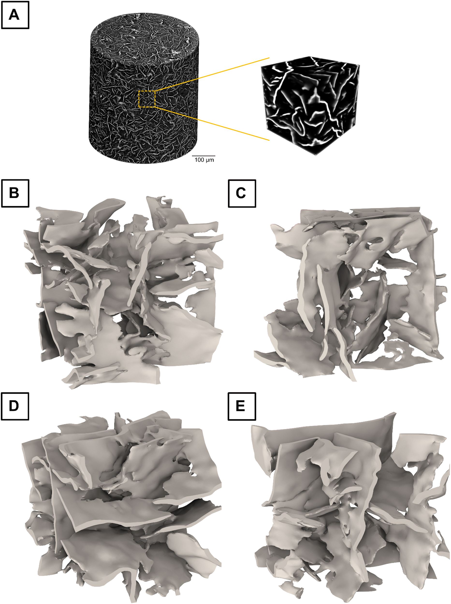 | ||
| Fig. 1 (A) Full 3D tomographic reconstruction of a monoglyceride-based oleogel obtained by phase-contrast X-ray tomography. The dark colors are regions of liquid oil, whereas the bright colors are solid monoglycerides. Microscopic representative volume elements (RVEs) are sampled from the full reconstruction. (B)–(E) Examples of RVE revealing the microscopic structure of the monoglyceride crystal network. The edge size of the RVE cube is 60 μm. | ||
The full image in Fig. 1(A) contains excessive details for efficient visualization and modeling. Therefore, individual RVEs of the MG structure were extracted, where the oil had been removed. Four examples of such RVEs are shown in Fig. 1(B)–(E). The orientations of platelets were random, such that the sample was isotropic on a macroscopic scale. The platelets appeared bent and had uneven surfaces, which made it difficult to precisely specify their length and thickness. However, by manually inspecting the RVEs, we estimated the platelet length to be on average 43 μm (standard deviation of 15 μm) and the thickness to be 1.8 μm (standard deviation of 0.4 μm). These rough estimates were not used in any calculations but are rather presented here to illustrate the scale of the microstructure. It is known that fast cooling leads to smaller structures compared to slow cooling.53 When cooling quiescently at room temperature, the cooling rate is faster for smaller samples and slower for larger samples. Therefore, our small sample in the pipette tip was expected to have smaller structures compared to similar samples produced in a beaker or Petri dish. For example, using optical microscopy techniques, a size-estimate of approximately 57 μm has been reported for similar oleogels, when using a cooling profile representing 30 mL cylindrical containers at an ambient temperature of 17.5 °C.30 The surface roughness of the platelets cannot be accurately estimated due to the limited pixel size of 502 nm and smoothing caused by the reconstruction algorithm. Surface roughness is not expected to affect mechanical properties such as shear modulus.
The solid fraction of each RVE was calculated to observe whether it correlates with the effective shear modulus. Even though the macroscopic sample was prepared to have a homogeneous solid fraction of 10% (w/w) in its entire volume, the local solid fraction of a microscopic RVE can deviate from this value. The RVEs considered in this article were found to have solid fractions ranging from 6.7% to 13.1%. This variation can be explained by the formation of microscopic domains of more densely packed crystal network portions connected by more loosely packed ones.
3.2 FEM of a plain oleogel
After successfully obtaining 16 instances of RVE from the MG-based oleogel, we proceeded with their micromechanical FEM (these oleogels are referred to as plain because they lack materials other than MG and oil). In order to obtain necessary bulk mechanical properties, we analyzed samples of pure MG in β-polymorphic form. The form was verified by X-ray diffraction (shown in Fig. S1, ESI†). This is the form that MG crystallizes into when forming MG-based oleogels.55 We then used torsional oscillatory rheology to measure the mechanical properties of pure MG. The measurements revealed a storage modulus that was independent of the strain amplitude for small strains (see Fig. S2, ESI†). The small-strain storage moduli for three MG samples were 610, 630, and 680 MPa. The average value of these measurements, 640 MPa, was chosen to be a representative value for the shear modulus of the pure MG in β-polymorphic form. More information about the effect of MG polymorphism on its mechanical properties is discussed in the ESI.† The shear modulus value of 640 MPa is used as input in all finite element modeling discussed in this work. The value for the bulk modulus was set to 6400 MPa (as discussed in Section 2.5.1).Fig. 2(A) shows the calculated effective shear modulus as a function of RVE solid fraction for the plain oleogel. The modulus ranges from 0.3 MPa to 2.6 MPa within the range of solid fractions between 6.7% and 13.1%. Although we observed a clear positive correlation between the microscopic solid fraction and shear modulus, the data points do not follow a clear curve. This is expected because the RVE only includes a limited amount of microstructure. The limited size also causes the microscopic RVE to have an anisotropic mechanical response. The macroscopic shear modulus of an entire sample that could be observed in a rheological measurement is expected to be isotropic and approximately follow the average of a large number of RVE calculations. In this case, the average of the calculated 16 moduli is 1.6 MPa, which is of the expected order of magnitude for an ideal undamaged oleogel, such as those directly crystallized in the measuring geometry of a rheometer. A storage modulus of 1.92 MPa has been measured for an oleogel (10% (w/w) of MG, myverol 18-08 NP) crystallized in a rheometer using a programmed cooling rate that mimicked ambient temperature of 30 °C.30
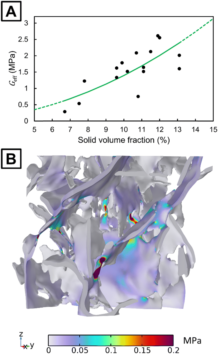 | ||
| Fig. 2 (A) Calculated effective shear moduli for representative volume elements of a plain oleogel. Each black point represents a unique microstructure. The green curve shows a power-law fit to the data points. The dashed part of the curve shows predictions outside the region of fitting. (B) Distribution of von Mises stress in an RVE under simple shear. A shear strain of 0.01% is applied in the positive y-direction on the top z boundary. The geometrical deformation is magnified by a factor of 1000 for better visualization. | ||
There are several practical obstacles to obtaining a storage modulus greater than 1 MPa using MG-based oleogels of 10% solid fraction. First, it is convenient to crystallize oleogels in a beaker and then transfer them to a rheometer for measurement. However, this process can easily damage the microstructure, resulting in a reduced shear modulus. Second, the cooling temperature profile is of critical importance and generally faster cooling results in a lower shear modulus. For example, reducing the ambient temperature from 30 °C to 5 °C was found to reduce the modulus from 1.92 MPa to 0.357 MPa,30 while using a constant cooling rate of 2 °C min−1 yielded 0.4 MPa.56 In a study involving fast cooling using a circulating water bath and transfer of the sample from the beaker to a rheometer, moduli in the range of 0.1–0.3 MPa were found. Finally, the modulus is also greatly affected by the type of monoglyceride57 and oil55 that is used.
After obtaining the shear modulus and solid volume fraction for each RVE, we fitted a power-law given by eqn (1) to the data. Results from the considered RVE models have a too high variance to justify the precise determination of the exponent n. We attempted to obtain n by calculating the fractal dimension from the 3D tomographic data. However, the calculated local dimension did not converge with reducing the box size (see Fig. S4, ESI†). This suggests that the image data are not fractal. Therefore, we consider as a hypothesis that n = 2, which is the value that can be analytically derived for open-cell foams.58 MG oleogels at 10% concentration (same as that used in this work) have been experimentally observed to behave as cellular foams,59 which supports our assumption regarding the value of the exponent n. The 3D reconstruction in Fig. 1 also shows large open volumes of fluid surrounded by a connected crystalline network, which has a resemblance to that of an open-cell foam.
A value of γ equal to 139.46 MPa is obtained by fitting using the method of least-squares. The fit is shown by the solid green line in Fig. 2(A). The data points show a correlation with the fit (R2 = 0.50), which suggests that a quadratic polynomial-law could be a coarse approximation for the effective shear modulus at a microscopic level. MG-based oleogels with concentrations of 5% (w/w) and 15% (w/w) have often been considered.13 Therefore, predictions of the fit are also shown for solid fractions outside the region of fitting by the dashed lines in Fig. 2(A).
A high variance of the shear modulus was observed between the RVEs of similar solid fractions. Looking at the stress distribution in Fig. 2(B), we observed that the stress is the highest in the interconnections between the platelets. The number and width of interconnections are different across the considered RVEs. This could explain part of the observed variance. These results suggest that particular attention should be given to the crystallization process. If the crystal growth can be optimized to maximize these interconnections, the mechanical properties could be enhanced. In addition, the number of nuclei and their positions are important to consider as they affect the platelet size distribution and number of interconnections, further contributing to the mechanical properties of oleogels.
3.3 FEM of composite oleogels containing spherical inclusions
Spherical or nearly spherical inclusions can be added to an oleogel matrix, such as solid particles,42,60 hydrogels,47 air bubbles,48 or encapsulated droplets of a secondary oleogel.49 In the literature, significant modification of the oleogel's mechanical properties due to these inclusions was observed experimentally. Yet, an accurate theoretical description of the effect of inclusions is missing due to the lack of 3D models of an oleogel's microscopic structure. Using our 3D tomographic reconstruction, we can investigate the effect of inclusions in a digital environment. Particles were added to an RVE to evaluate their effect on the mechanical response of an oleogel. Fig. 3 shows one of the created RVEs for such a particle-containing oleogel. We considered an ideal case of monodisperse spherical particles. Using FEM, we calculated the effect of three different parameters: particle concentration, particle size, and particle material. In each study, one of the parameters was varied, while keeping the remaining two fixed.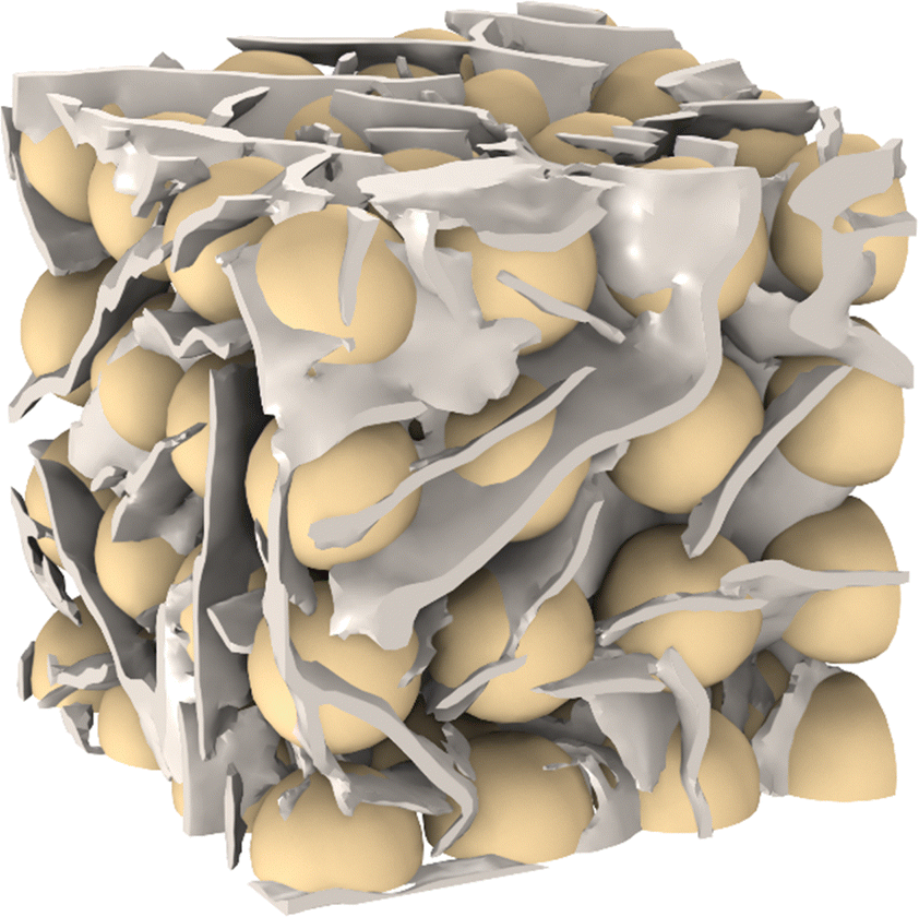 | ||
| Fig. 3 A cubic representative volume element for an oleogel that has been reinforced by particles. Monoglyceride and particles are shown in white and yellow colors, respectively. The size of the cube is 80 μm and the particle volume fraction is 40%. | ||
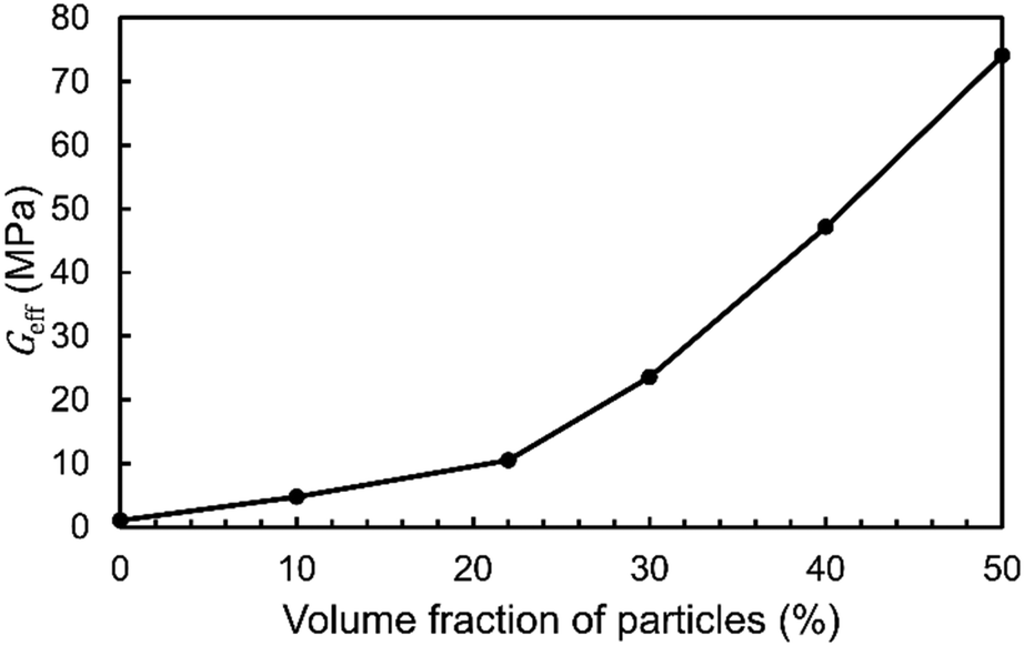
The effective shear modulus of the chosen RVE without particles was 1.07 MPa. This value is slightly lower than those calculated in the previous section. We attribute this to the increased RVE size because due to non-ideal boundary conditions, the modulus has a slight dependence on the RVE size. The MG solid content in this RVE was 11.1% prior to adding the particles. The addition of particles with a diameter of 20 μm and made of microcrystalline cellulose increases the effective shear modulus as shown in Fig. 4. The results show that for a particle concentration of 10% (v/v), the modulus increases by a factor of 4.5. For the highest calculated particle concentration of 50% (v/v), the modulus increases by a factor of 69. In a previous study, a factor of approximately 40 was reported for non-spherical fiber-shaped particles at a weight fraction of 40% (w/w) which corresponds to 24% (v/v).42 Our calculations give a factor of 13 at 24% (v/v), which is lower. This could suggest that fiber-shaped particles are more efficient at strengthening the material compared to spheres at the same volume fraction. It should be noted that the increase of the modulus depends on the chosen RVE and the positioning of the particles within the RVE. Thus, it can be expected that the mechanical reinforcement is stochastic on a microscopic scale.
 | ||
| Fig. 4 Calculated effective shear moduli for representative volume elements of particle-reinforced oleogels. Each black point shows the result of a chosen volume fraction of particles. The particle diameter is 20 μm and the material is microcrystalline cellulose. | ||
Particles modify a composite oleogel's mechanical properties both directly, through the stiffness of the particles, and indirectly, by modifying the crystal structure. In a previous study, it was observed that platelets may switch to spherulites in MG-based composite oleogels.42 However, in this study, we decided to only consider the direct effect of the particles and assume that there would be no change to the crystal microstructure if inclusions were added. The impact of the indirect modification of the crystal structure depends on the choice of structurants and particles.42 For example, it has also been reported that spherical starch particles do not substantially influence nucleation and crystallization when added to a lipid gel composed of oil and tripalmitin.43
The effect of the particle size on the effective shear modulus is shown in Fig. 5. Surprisingly, the effect is very small in a range of diameters between 15 μm and 50 μm. However, for 5–10 μm particles, the modulus is reduced. The particles reinforce the oleogel by linking together the platelets. This suggests that if the particle size is significantly smaller than the platelet dimensions, this linking may not occur as effectively. This is in agreement with experimental observations for fiber-reinforced oleogels in which nanocrystalline cellulose yielded a lower modulus compared to microcrystalline cellulose.42 In the same article, microcrystalline cellulose fibers of 55 μm length were also observed to yield a larger modulus compared to fibers of 15 μm length, but the difference was smaller compared to the difference to nanocrystalline cellulose. Although it should be noted that the material properties of those fibers were most likely not identical as they were from different manufacturers.
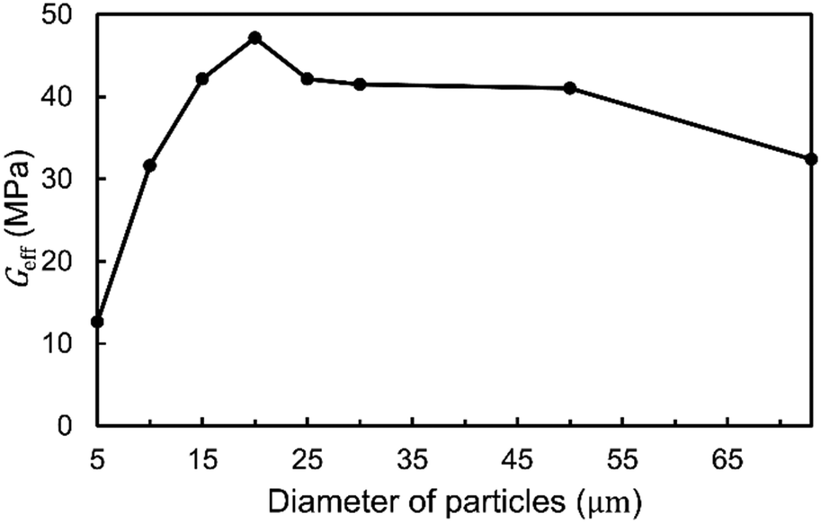 | ||
| Fig. 5 Calculated effective shear moduli for representative volume elements of particle-reinforced oleogels. Each black point shows the result of a chosen diameter of particles. The particle volume fraction is 40% and the material is microcrystalline cellulose. | ||
In Fig. 5, the results for the larger particles of 50 μm and 73 μm have a higher degree of uncertainty due to only a few particles fitting into the considered RVE. Therefore, they cannot be used to make statements regarding the asymptotic behavior of even larger particles. When using particles composed of encapsulated oleogels, it has been reported that spheres with a size of 5–20 μm have a good encapsulation efficiency that is better than that of non-spherical morphologies.49 Undesired sensory detection of particles may occur if particles are too large. In a sensory experiment, microcrystalline cellulose particles of 50 μm were detectable in certain food products at a low concentration of 1.5% (w/w).61 Therefore, we expect several applications to prefer a particle-size range of 10–50 μm, which is included in the range calculated here.
The reinforcement provided by particles depends not only on their concentration but also on their material properties. To illustrate the effect of material choice, we computed the effective shear modulus for a range of materials. In Table 2, we present the calculated moduli of the resulting composite oleogels having a 40% particle volume fraction. In general, we observed that the effect of the type of material on the overall modeled mechanical response of composite oleogels greatly depends on the particle's shear modulus. Interestingly, even the addition of a softer material such as medium cross-linking density silicone can increase the effective shear modulus. However, if the material is too weak, such as low cross-linking density silicone, the composite oleogel becomes weaker than the plain oleogel. This is due to the inability of this weak material to effectively transmit shear forces. Indeed, particles made of this weak silicone partially replace the stiffer MG platelets, which weakens the resulting oleogel. We also considered the case where the particle material is set to liquid. Particles made of fluids such as liquids or air are unable to transmit the shear forces, resulting in the modulus being greatly decreased. This effectively corresponds to removing parts of the monoglyceride crystals, which results in a broken crystal network and lower solid content. In contrast, adding rigid particles such as iron can greatly increase the oleogel's shear modulus.
| Material | G eff (MPa) |
|---|---|
| No particles | 1.07 |
| Liquid | 0.07 |
| Silicone (low cross-linking density) | 0.72 |
| Silicone (medium cross-linking density) | 9.05 |
| Microcrystalline cellulose | 47.2 |
| Iron | 54.5 |
In combination, the data in Fig. 4 and 5 and Table 2 reveal that a wide range of material properties can be achieved by simultaneously varying the particle concentration and composition. As an example, 30 μm sized microcrystalline cellulose particles at even a low concentration of 10–20% could be used to make composite gels of high elasticity. Another option could be 15 μm sized low cross-linking density silicone particles at a high volume fraction to achieve a composite oleogel with a similar shear modulus to that of the plain oleogel, but with a widely different composition. This could be helpful for delivering additional nutritional value in food products or reactive ingredients in cosmetic applications.
4 Conclusions
We have introduced a micromechanical model for crystalline lipid-based materials based on the exact 3D crystal network. This network is obtained by using non-destructive X-ray tomography and properties such as the solid content, platelet thickness and length were analyzed. Generating RVEs of the crystal network allowed us to perform micromechanical FEM. For the considered example of an MG-based oleogel, the bulk mechanical properties of pure MG were measured and used in the model. Using the model, we were able to calculate the mechanical properties of the plain oleogel as well as composite oleogels with supposed spherical inclusions.In the presented modeling examples, we made no assumptions about the mechanical properties of the macroscopic oleogel. Instead, we investigated whether these properties could be calculated, given only the properties of the bulk materials and their microscopic structure. The calculated effective shear modulus for the plain oleogel falls in the expected range of similar undamaged oleogels, which confirms the validity of the approach.
The modeling of composite oleogels reveals that by suitably choosing particle inclusions, we can either greatly increase or decrease the elasticity of the resulting material. Composite materials with tailored mechanical properties can be created by merely varying the concentration and composition of particles. The introduced micromechanical approach provides a theoretical description for understanding how the particles should be chosen based on the desired properties of the composite material. Future research should be carried out to investigate the effect of polydisperse spherical particles and non-spherical particles, such as ellipsoidal ones. Furthermore, the effect of particles on nucleation and crystal growth needs more investigation. Micromechanical modeling should also be carried out for other types of lipid-based systems, such as wax-based oleogels, hydrogels, emulsions, and aerogels.
Author contributions
Patrick Grahn: conceptualization, data curation, formal analysis, investigation, methodology – modeling, software, validation, visualization, writing – original draft, and writing – review and editing. Petri Lassila: investigation, methodology – experimental, and writing – review & editing. Fabio Valoppi: conceptualization, investigation, resources, writing – original draft, and writing – review and editing.Data availability
The data supporting this article have been included as part of the ESI.† Further relevant data are available from the corresponding author upon reasonable request.Conflicts of interest
There are no conflicts to declare.Acknowledgements
We thank Dr Anke Dutschke from Carl Zeiss Microscopy GmbH for carrying out the imaging of the oleogel sample. We thank Heikki Räikkönen from the University of Helsinki, Faculty of Pharmacy, for carrying out X-ray diffraction measurements.References
- A. G. Marangoni, J. P. M. van Duynhoven, N. C. Acevedo, R. A. Nicholson and A. R. Patel, Soft Matter, 2020, 16, 289–306 RSC.
- S. Scioli Montoto, G. Muraca and M. E. Ruiz, Front. Mol. Biosci., 2020, 7, 587997 CrossRef PubMed.
- C. Viegas, A. B. Patrício, J. M. Prata, A. Nadhman, P. K. Chintamaneni and P. Fonte, Pharmaceutics, 2023, 15, 1593 CrossRef CAS PubMed.
- C. V. Kulkarni, Nanoscale, 2012, 4, 5779–5791 RSC.
- Ch. N. Patra, K. Sahu, R. Singha, G. K. Jena, S. Jammula and N. R. Das, Biomed. Mater. Devices, 2024, 2, 834–860 CrossRef CAS.
- A. G. Marangoni, N. Acevedo, F. Maleky, E. Co, F. Peyronel, G. Mazzanti, B. Quinn and D. Pink, Soft Matter, 2012, 8, 1275–1300 RSC.
- C. Palla and F. Valoppi, ed., Advances in Oleogel Development, Characterization, and Nutritional Aspects, Springer International Publishing, Cham, 2024 Search PubMed.
- C. Hald Albertsen, J. A. Kulkarni, D. Witzigmann, M. Lind, K. Petersson and J. B. Simonsen, Adv. Drug Delivery Rev., 2022, 188, 114416 CrossRef CAS PubMed.
- X. Hou, T. Zaks, R. Langer and Y. Dong, Nat. Rev. Mater., 2021, 6, 1078–1094 CrossRef CAS PubMed.
- B. A. Macias-Rodriguez and A. A. Marangoni, Crit. Rev. Food Sci. Nutr., 2018, 58, 2398–2415 CrossRef CAS PubMed.
- K. Sato, L. Bayés-García, T. Calvet, M. À. Cuevas-Diarte and S. Ueno, Eur. J. Lipid Sci. Technol., 2013, 115, 1224–1238 CrossRef CAS.
- M. Temkov and V. Mureşan, Foods, 2021, 10, 1376 CrossRef CAS PubMed.
- C. A. Palla, M. Dominguez and M. E. Carrín, Compr. Rev. Food Sci. Food Saf., 2022, 21, 2587–2614 CrossRef CAS PubMed.
- N. C. Acevedo and A. G. Marangoni, Cryst. Growth Des., 2010, 10, 3327–3333 CrossRef CAS.
- M. Sánchez-Becerril, A. G. Marangoni, M. J. Perea-Flores, N. Cayetano-Castro, H. Martínez-Gutiérrez, J. A. Andraca-Adame and J. D. Pérez-Martínez, Food Struct., 2018, 16, 1–7 CrossRef.
- D. A. Pink, B. Quinn, F. Peyronel and A. G. Marangoni, J. Appl. Phys., 2013, 114, 234901 CrossRef.
- F. Peyronel, J. Ilavsky, G. Mazzanti, A. G. Marangoni and D. A. Pink, J. Appl. Phys., 2013, 114, 234902 CrossRef.
- F. Peyronel, B. Quinn, A. G. Marangoni and D. A. Pink, J. Phys.: Condens. Matter, 2014, 26, 464110 CrossRef PubMed.
- F. Peyronel, B. Quinn, A. G. Marangoni and D. A. Pink, Food Biophys., 2014, 9, 304–313 CrossRef.
- F. Peyronel, D. A. Pink and A. G. Marangoni, Curr. Opin. Colloid Interface Sci., 2014, 19, 459–470 CrossRef CAS.
- P. R. R. Ramel, F. Peyronel and A. G. Marangoni, Food Chem., 2016, 203, 224–230 CrossRef CAS PubMed.
- R. J. Cordina, B. Smith and T. Tuttle, J. Chem. Inf. Model., 2022, 62, 5601–5606 CrossRef CAS PubMed.
- A. Pizzirusso, A. Brasiello, A. D. Nicola, A. G. Marangoni and G. Milano, J. Phys. D: Appl. Phys., 2015, 48, 494004 CrossRef.
- J. Cooney, S. Martini, F. Peyronel and D. Pink, J. Am. Oil Chem. Soc., 2024, 101, 657–662 CrossRef CAS.
- Z. Jiang, X. Lu, S. Geng, H. Ma and B. Liu, Food Chem., 2020, 324, 126801 CrossRef CAS PubMed.
- A. Matheson, G. Dalkas, R. Mears, S. R. Euston and P. S. Clegg, Soft Matter, 2018, 14, 2044–2051 RSC.
- I. A. Penagos, F. D. Witte, T. Rimaux, W. Chèvremont, I. Pintelon, K. Dewettinck and F. V. Bockstaele, Soft Matter, 2024, 20, 5071–5085 RSC.
- K. Rondou, F. De Witte, T. Rimaux, W. Dewinter, K. Dewettinck, J. Verwaeren and F. Van Bockstaele, J. Am. Oil Chem. Soc., 2022, 99, 1019–1031 CrossRef CAS.
- B. A. Macias-Rodriguez, F. Peyronel and A. G. Marangoni, J. Food Eng., 2017, 212, 87–96 CrossRef CAS.
- C. Palla, J. de Vicente, M. E. Carrín and M. J. Gálvez Ruiz, Food Res. Int., 2019, 125, 108613 CrossRef CAS PubMed.
- I. A. Penagos, F. De Witte, T. Rimaux, K. Dewettinck and F. Van Bockstaele, Crystals, 2024, 14, 566 CrossRef CAS.
- G. van Dalen, E. J. J. van Velzen, P. C. M. Heussen, M. Sovago, K. F. van Malssen and J. P. M. van Duynhoven, J. Raman Spectrosc., 2017, 48, 1075–1084 CrossRef CAS.
- K. J. A. Martens, G. van Dalen, P. C. M. Heussen, M. A. Voda, T. Nikolaeva and J. P. M. van Duynhoven, J. Am. Oil Chem. Soc., 2018, 95, 259–265 CrossRef CAS.
- D. W. Pepper and J. C. Heinrich, The Finite Element Method: Basic Concepts and Applications with MATLAB, MAPLE, and COMSOL, CRC Press, Boca Raton, 3rd edn, 2017 Search PubMed.
- J. Gonzalez-Gutierrez and M. G. Scanlon, in Structure-Function Analysis of Edible Fats, ed. A. G. Marangoni, AOCS Press, 2nd edn, 2018, pp. 119–168 Search PubMed.
- J. Roesler, H. Harders and M. Baeker, Mechanical Behaviour of Engineering Materials: Metals, Ceramics, Polymers, and Composites, Springer, 2007 Search PubMed.
- J. Bergström, Mechanics of solid polymers: theory and computational modeling, Elsevier, 2015 Search PubMed.
- S. Krödel, L. Li, A. Constantinescu and C. Daraio, Mater. Des., 2017, 130, 433–441 CrossRef.
- S. S. Narine and A. G. Marangoni, Phys. Rev. E: Stat. Phys., Plasmas, Fluids, Relat. Interdiscip. Top., 1999, 59, 1908–1920 CrossRef CAS.
- J. D. Pérez-Martínez, M. Sánchez-Becerril, A. G. Marangoni, J. F. Toro-Vazquez, J. J. Ornelas-Paz and V. Ibarra-Junquera, Food Res. Int., 2019, 122, 471–478 CrossRef PubMed.
- F. Moisy, Boxcount (version 1.0.0.0), https://www.mathworks.com/matlabcentral/fileexchange/13063-boxcount, 2008 Search PubMed.
- M. Bhattarai, P. Penttilä, L. Barba, B. Macias-Rodriguez, S. Hietala, K. S. Mikkonen and F. Valoppi, LWT–Food Sci. Technol., 2022, 160, 113331 CrossRef CAS.
- B. A. Macias-Rodriguez and K. P. Velikov, Food Struct., 2022, 32, 100257 CrossRef CAS.
- B. Cappella, J. R. Wassenberg, L.-O. Heim, M. Klostermann, J. Venzmer and E. Bonaccurso, Polymer, 2014, 55, 1209–1216 CrossRef CAS.
- R. J. Roberts, R. C. Rowe and P. York, Int. J. Pharm., 1994, 105, 177–180 CrossRef CAS.
- J. A. Rayne and B. S. Chandrasekhar, Phys. Rev., 1961, 122, 1714–1716 CrossRef CAS.
- A. Shakeel, U. Farooq, D. Gabriele, A. G. Marangoni and F. R. Lupi, Food Hydrocolloids, 2021, 111, 106190 CrossRef CAS.
- A.-L. Fameau and A. Saint-Jalmes, Front. Sustain. Food Syst., 2020, 4, 110 CrossRef.
- S. Sabet, A. A. Kazerani García, S. Kirjoranta, T. C. Pinto, M. Siven, M. Bhattarai, L. Barba and F. Valoppi, Food Hydrocolloids, 2024, 153, 110068 CrossRef CAS.
- A. I. Blake and A. G. Marangoni, Food Struct., 2015, 3, 30–34 CrossRef.
- C. D. Doan, I. Tavernier, M. D. B. Sintang, S. Danthine, D. Van de Walle, T. Rimaux and K. Dewettinck, Food Biophys., 2017, 12, 97–108 CrossRef.
- Y. Miyazaki and A. G. Marangoni, Mater. Res. Express, 2014, 1, 025101 CrossRef CAS.
- F. Valoppi, S. Calligaris and A. G. Marangoni, Eur. J. Lipid Sci. Technol., 2017, 119, 1600252 CrossRef.
- M. A. Rogers, Q. Feng, V. Ladizhansky, D. B. Good, A. K. Smith, M. Corridini, D. A. S. Grahame, B. C. Bryksa, P. D. Jadhav, S. Sammynaiken, L.-T. Lim, B. Guild, Y. Y. Shim, P.-G. Burnett and M. J. T. Reaney, RSC Adv., 2016, 6, 40765–40776 RSC.
- F. Valoppi, S. Calligaris, L. Barba, N. Šegatin, N. Poklar Ulrih and M. C. Nicoli, Eur. J. Lipid Sci. Technol., 2017, 119, 1500549 CrossRef.
- I. M. Cotabarren, S. Cruces and C. A. Palla, Food Res. Int., 2019, 126, 108676 CrossRef CAS PubMed.
- Y. Zhang, J. Xu, C. Tang and Y. Li, Foods, 2023, 12, 345 CrossRef CAS PubMed.
- L. J. Gibson and M. F. Ashby, Cellular solids: structure and properties, Cambridge, 2nd edn, 1997 Search PubMed.
- P. Lassila, F. Valoppi, O. Tommiska, J. Hyvönen, A. Holmström, S. Hietala, A. Salmi and E. Haeggström, Ultrason. Sonochem., 2022, 85, 105970 CrossRef CAS PubMed.
- B. A. Macias-Rodriguez, R. Gouzy, C. Coulais and K. P. Velikov, Soft Matter, 2024, 20, 3033–3043 RSC.
- M. Santagiuliana, I. S. Marigómez, L. Broers, J. E. Hayes, B. Piqueras-Fiszman, E. Scholten and M. Stieger, Food Funct., 2019, 10, 5386–5397 RSC.
Footnote |
| † Electronic supplementary information (ESI) available. See DOI: https://doi.org/10.1039/d4mh01891e |
| This journal is © The Royal Society of Chemistry 2025 |