 Open Access Article
Graphene spatiotemporal reconfigurable intelligent surface (GSRIS) for terahertz polarization-state manipulation and holographic imaging
Tianyu Maa,
Liming Si *ab,
Chenyang Danga,
Rong Niua,
Genhao Wua,
Xiue Baoa,
Houjun Sunab and
Weiren Zhu
 *c
*c
aBeijing Key Laboratory of Millimeter Wave and Terahertz Technology, School of Integrated Circuits and Electronics, Beijing Institute of Technology, Beijing 100081, People's Republic of China. E-mail: lms@bit.edu.cn
bTangshan Research Institute of Beijing Institute of Technology, Tangshan 063007, People's Republic of China
cDepartment of Electronic Engineering, Shanghai Jiao Tong University, Shanghai 200240, People's Republic of China. E-mail: weiren.zhu@sjtu.edu.cn
First published on 7th January 2025
Abstract
The integration of 2D materials and metamaterials/metasurfaces presents an effective approach for the intelligent, real-time dynamic control of electromagnetic (EM) waves in the terahertz (THz) frequency range. Herein, we demonstrate a graphene spatiotemporal reconfigurable intelligent surface (GSRIS) for THz polarization-state manipulation, multi-beam generation and holographic imaging using EM theory and full-wave EM simulations. The chemical potential of graphene can be changed through time-varying modulation, such as field-programmable gate arrays (FPGAs), of the electric field or voltage. By dynamically controlling the spatiotemporal chemical potential of graphene, both the amplitude and phase of orthogonally polarized reflected waves can be simultaneously adjusted, enabling polarization state manipulation at different harmonics, multi-beam generation, and holographic imaging. As a proof of concept, a multifunctional GSRIS designed for 1.3 THz demonstrates polarization-state manipulation and multi-beam generation at the +1st order harmonic, as well as high-quality holographic imaging at the -1st order harmonic. The presented GSRIS provides a novel approach for designing THz circuits and systems, which can exhibit various potential applications in imaging, sensing, beam control, and 6G wireless communications.
1. Introduction
Over the past decades, terahertz (THz) technology has attracted significant attention owing to its extensive applications in many fields such as biomedicine,1 space exploration,2 material characterization,3 radio astronomy,4 sensing,5 imaging,6 and 6G wireless communications.7 Numerous intriguing phenomena have been studied within the THz frequency range, including the vibrational resonances of many molecules that fall within the THz and mid-IR frequency regions.8 However, the generation, manipulation, and detection of THz waves remain significantly constrained by the lack of effective materials and technologies compared to the microwave and optical regimes, often referred to as the “THz gap”.9 As a result, the discovery and development of novel materials optimized for the THz frequency range are essential for advancing THz technology and applications. Two-dimensional (2D) materials, such as graphene, MXene and black phosphorus, offer a powerful platform for the generation, manipulation and detection of THz waves, particularly in active and reconfigurable applications.10 Additionally, metamaterials and metasurfaces, composed of artificial subwavelength meta-atoms, provide opportunities to achieve unconventional electromagnetic (EM) properties not easily found in nature.11–16 Therefore, the integration of 2D materials and metamaterials/metasurfaces presents an effective approach for intelligent real-time dynamic control of EM waves at THz frequencies.Graphene is widely regarded as one of the most distinctive 2D materials for realizing tunable THz devices and applications.17 It is well known that graphene is composed of a 2D honeycomb lattice structure of carbon atoms, exhibiting remarkable electronic, mechanical, and thermal properties.18 The EM properties of graphene can be dynamically adjusted using electric fields, chemical doping, or mechanical folding methods. This tunability creates significant opportunities for innovations in THz filters, antennas, absorbers, modulators, as well as high-speed communications, imaging, and sensing.19,20 However, it is worth noting that the properties of graphene are very sensitive to the type of edge atoms in a honeycomb lattice.21 The type of edge atoms in graphene, whether armchair or zigzag, is determined on the basis of the orientation and structural configuration of graphene.22 Variations in graphene's orientation and structure can give rise to new electronic states as well as transitions among insulating, conductive, and even superconductive behaviors.23,24 Hence, we can argue that this phenomenon causes graphene to behave as an anisotropic and time-varying material, thereby enabling distinct space-time modulation in the THz range.
Reconfigurable intelligent surfaces (RISs) are a type of 2D metamaterial, specifically a metasurface, composed of periodic or aperiodic subwavelength meta-atoms.25 They can effectively control EM waves, including reflection and transmission in terms of amplitude, phase and polarization.26–31 In the microwave frequency range, a straightforward approach to implementing RISs is to use reconfigurable metasurfaces incorporating positive-intrinsic-negative (PIN) diodes,32 varactor diodes,33 transistors,34 mechanical folding,35 or microelectromechanical system (MEMS) devices36 within meta-atoms. In recent years, RISs have evolved from focusing solely on the spatial domain to incorporating the temporal domain, leading to the development of spatiotemporal RISs.37,38 This advancement has revealed a variety of new phenomena, including harmonic control,39 time-reversal symmetry for non-reciprocal transmission,40,41 and real-time manipulation of multiple polarization states.42 Additionally, advancements in dynamic metasurfaces have demonstrated promising results in controlling THz waves. For instance, tunable metasurfaces based on phase-change materials or graphene have been shown to enable beam steering,43 polarization conversion,44 and broadband absorption.45 Spatiotemporal RISs are considered effectively applicable in various areas of microwave technology, such as beam steering, holographic imaging, real-time radar detection, wireless communication, and unmanned aerial vehicles (UAVs).46,47 Although advanced THz systems with precise real-time control are highly desirable,48 implementing spatiotemporal RISs at THz frequencies remains a significant challenge due to material limitations and integration issues.
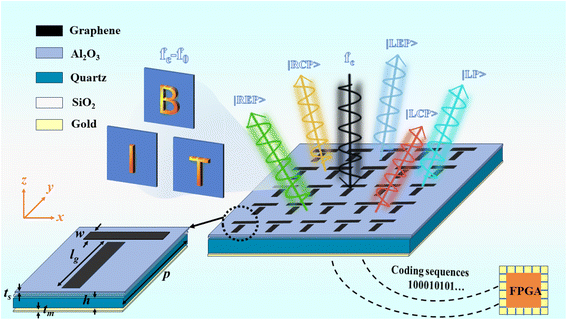
In this work, we present a configuration for implementing spatiotemporal RISs at THz frequencies through the integration of graphene and metasurfaces, which is herein called a “graphene spatiotemporal reconfigurable intelligent surface” (GSRIS). The proposed GSRIS, operating in the THz frequency range, significantly enhances its versatility and performance in real-time applications. We theoretically calculate and numerically analyze the performance of the GSRIS using EM theory and full-wave EM simulations, focusing on THz polarization state manipulation, multi-beam generation, and holographic imaging. When illuminated with light of specific frequency and polarization states, the GSRIS can be programmatically controlled to produce variable polarization and spatially multiplexed beams through harmonic frequency conversion. By altering time-varying external polarization voltage to control the chemical potential of graphene, such as through a, FPGAs, independent modulation of each unit can be achieved. As verification, the designed GSRIS successfully generates one-to-four beam channels with different polarization states at the +1st order harmonic, with each channel exhibiting different scattering modes. In addition, THz holographic imaging is realized at the -1st order harmonic, demonstrating high-resolution imaging capabilities. The proposed GSRIS enhances the potential of metasurfaces in THz applications, including imaging, sensing, beam control, and 6G wireless communications.
2. Materials and methods
Fig. 1 shows the designed GSRIS simultaneously generating multiple beams with different polarization states. The unit structure that supports independent control of each meta-atom's x and y polarizations is depicted in the figure. The proposed GSRIS unit is composed of multiple layers of different materials arranged from top to bottom. The combination of the top orthogonal graphene strips enables independent control over orthogonal EM responses, with the length and width of the graphene sheets being lg = 18 μm and w = 3.9 μm, respectively. Below this is a layer of Al2O3 and SiO2, each with a thickness of ts = 65 nm. The relative permittivity of Al2O3 is εr, Al = 9.9. There is a quartz substrate with a thickness of h = 27 μm (with εr = 3.75 and tan![[thin space (1/6-em)]](https://www.rsc.org/images/entities/char_2009.gif) δ = 0.0184). The metal ground layer terminates the metasurface to avoid energy transmission, thereby creating a reflective digital metasurface. The electrical conductivity of the metal is σ = 4.56 × 10⁷. Full-wave simulations of the co-polarized reflection coefficient of the GSRIS were conducted using commercial CST Microwave Studio 2020 software. Periodic boundary conditions were applied in the x and y directions to simulate an infinite array, while open boundary conditions were applied in the z direction.
δ = 0.0184). The metal ground layer terminates the metasurface to avoid energy transmission, thereby creating a reflective digital metasurface. The electrical conductivity of the metal is σ = 4.56 × 10⁷. Full-wave simulations of the co-polarized reflection coefficient of the GSRIS were conducted using commercial CST Microwave Studio 2020 software. Periodic boundary conditions were applied in the x and y directions to simulate an infinite array, while open boundary conditions were applied in the z direction.
Considering the M × N spatiotemporal encoded GSRIS, graphene is chosen as the tunable material. Because of its high sensitivity to external gate bias, graphene can dynamically control terahertz frequency EM waves with a fast response time. Furthermore, owing to its single-layer structure, graphene can be modeled as an infinitely thin surface with a specific surface conductivity (σs). The surface conductivity of graphene is the sum of the intra-band (σintra) and inter-band (σinter) conductivities, which is defined as follows using the Kubo formula:49
| σs = σintraω,μc,Γ,T + σinterω,μc,Γ,T | (1) |
 | (2) |
 | (3) |
 | (4) |
 is Fermi velocity. Therefore, in the terahertz region, graphene is well described by Drude-like surface conductivity, and its sheet conductivity can be controlled by chemical potential (μc). A design for an anisotropic GSRIS that supports independent control of the x- and y-polarized responses of each unit is implemented.
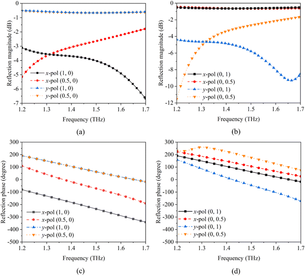
Co-polarized reflection simulations for x- and y-polarized incidence are presented in Fig. 2. Herein, the chemical potentials in the x- and y-polarization directions are denoted as (μx,μy), respectively. Independent control of reflection coefficients for x- and y-polarized waves could be achieved by adjusting the chemical potentials μx and μy applied to the graphene strips along the x- and y-axes. Fig. 2 depicts amplitude and phase representations for two different working states based on the chemical potential combinations. For example, (0, 1) represents μx = 0 eV and μy = 1 eV, and (0, 0.5) represents μx = 0 eV and μy = 0.5 eV. As shown in Fig. 2, when either μx or μy is fixed, corresponding polarization amplitude and phase remain consistent, while the chemical potential of the altered polarization can maintain a phase difference of 180° ± 20° in the range of 1.2–1.7 THz. These results demonstrate that the designed unit structure enables independent control of x and y polarizations, with no mutual interference between them. Herein, we selected 1.3 THz as the working frequency (fc). Meanwhile, in our design, by regulating the chemical potential, a phase difference of 180° can be achieved. At positions (0, 0.5) or (0.5, 0), the phase is 180°, while at positions (0, 1) h or (1, 0), the phase is 0°. Here, the code “1” corresponds to a 180° phase, and the code “0” corresponds to a 0° phase.
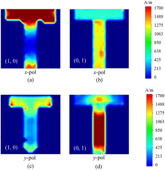
To further explore the polarization manipulation mechanism of the proposed cross structure, the surface current distribution of the unit cell in two operating states was simulated. As shown in Fig. 3, these surface current maps represent the unit at 1.3 THz for two different graphene chemical potentials. We examined two different cases of applying chemical potential to graphene, with 1 eV applied to graphene in both the x and y directions. It can be observed that when chemical potential is varied in either the x or y direction, current density in the same polarization direction on the side where the chemical potential is applied is significantly higher than in the other direction. Therefore, the designed GSRIS unit can independently control the reflection of x and y polarized light with minimal polarization crosstalk.
3. Results and discussion
3.1. Polarization-state manipulation at the +1st order harmonic
To achieve spatiotemporal modulation of multi-beam polarization control at the +1st order harmonic, a two-step process is necessary. The initial step entails the computation of the theoretical phase and amplitude patterns that will produce the desired polarization state of the targeted beam. Subsequently, in the second step, spatiotemporal coding techniques are employed to implement the calculated phase and amplitude distribution. This step utilizes specific optical components or systems that can modulate the beam's spatial and temporal properties. By doing so, phase and amplitude variations can be precisely controlled to generate the desired multi-beam polarization control. By integrating these two steps, a comprehensive approach is established to generate spatiotemporally modulated multi-beam polarization control at the +1st order harmonic.First, we assume that modulation frequency is much lower than the frequency of EM waves. Spatiotemporal encoding theory is derived using a physical optics model approximation, where mutual coupling between encoding units is temporarily neglected in the approximate model. Modulation frequency in time is much smaller than the frequency of EM waves. Assuming that the required light beam is generated by a GSRIS consisting of M × N meta-atoms and that it supports independent control of x- and y-polarized responses for each meta-atom, the far-field electric field can be represented as the collective result of all meta-atoms:
 | (5) |
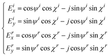
By modulating phase discontinuities and orthogonally polarized reflective fields, a single beam with a specified polarization state can be achieved. According to Snell's law, the addition of phase gradients (dΦ/dl) determines the scattering direction of the beam. To achieve the desired polarization state, the orthogonal polarized electric field E(χ,ψ) should contain x-polarized and y-polarized components:50
 | (6) |
Ex = cos![[thin space (1/6-em)]](https://www.rsc.org/images/entities/char_2009.gif) ψ ψ![[thin space (1/6-em)]](https://www.rsc.org/images/entities/char_2009.gif) sin sin![[thin space (1/6-em)]](https://www.rsc.org/images/entities/char_2009.gif) χ − j χ − j![[thin space (1/6-em)]](https://www.rsc.org/images/entities/char_2009.gif) sin sin![[thin space (1/6-em)]](https://www.rsc.org/images/entities/char_2009.gif) ψ ψ![[thin space (1/6-em)]](https://www.rsc.org/images/entities/char_2009.gif) cos cos![[thin space (1/6-em)]](https://www.rsc.org/images/entities/char_2009.gif) χ χ |
Ey = sin![[thin space (1/6-em)]](https://www.rsc.org/images/entities/char_2009.gif) ψ ψ![[thin space (1/6-em)]](https://www.rsc.org/images/entities/char_2009.gif) cos cos![[thin space (1/6-em)]](https://www.rsc.org/images/entities/char_2009.gif) χ − j χ − j![[thin space (1/6-em)]](https://www.rsc.org/images/entities/char_2009.gif) cos cos![[thin space (1/6-em)]](https://www.rsc.org/images/entities/char_2009.gif) ψ ψ![[thin space (1/6-em)]](https://www.rsc.org/images/entities/char_2009.gif) sin sin![[thin space (1/6-em)]](https://www.rsc.org/images/entities/char_2009.gif) χ χ |
The matrices Ex and Ey represent the Jones matrices of the polarization state of any point light in the Poincaré sphere, which are based on the basis vectors of linear polarization in the x and y directions, respectively. The polarization state of the light beam is controlled by Ex and Ey. Therefore, we set the incident light to be vertically incident on the GSRIS. This configuration allows us to obtain the theoretical phase and distribution of the light beam with the specified polarization state. By combining eqn (5) and (6), it is possible to achieve a single beam with the desired polarization state by adjusting the amplitude and phase responses of each meta-atom.
 | (7) |
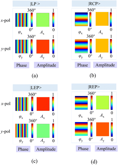
Here, we define |LP〉|LP〉|LP〉 as linearly polarized, |RCP〉 as right-handed circularly polarized, |LEP〉 as left-handed elliptically polarized, and |REP〉 as right-handed elliptically polarized. To verify the ability of the designed GSRIS to generate patterns in different polarization directions, we conducted theoretical calculation for a 10 × 10 array. Our goal, as shown in Fig. 4, was to generate four beams with distinct polarization states and deflection directions. Each of these beams has the following properties: |LP 52°〉 with (θ,ϕ) = (0°, 36°), as shown in Fig. 4(a); |LEP〉 with (χ,ψ) = (30°, 25°) and (θ,ϕ) = (180°, −36°), as shown in Fig. 4(c); |RCP〉 with (θ,ϕ) = (90°, −16°), as shown in Fig. 4(b); and |REP〉 with (χ,ψ) = (−12°, 57°) and (θ,ϕ) = (270°, 16°), as shown in Fig. 4(d). In this context, χ and ψ determine the polarization state of the beam, whereas θ and ϕ determine the deflection angle of the beam. In this case, using a linearly polarized (LP) light beam as an example, the EM properties of each meta-atom are designed with Ay/Ax = tan(52°), and the phase difference between the x and y directions is 0, i.e.,φx = φy. Additionally, 0 achieve the desired beam deflection angle of 36°, an additional phase gradient of dΦ/dx = 1.22π/λc is determined using the generalized Snell's reflection law.
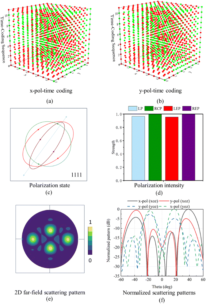
The final amplitude and phase distribution of the single beam with a 36° deflection angle and a linear polarization state of 52° are obtained. Here, we assess the polarization state by the amplitude ratio and phase difference between the x-polarized and y-polarized components. Therefore, the solution is not unique. Each pattern is accompanied by the normalized intensity of different polarization states. Selecting “1111” provides a far-field normalized scattering pattern, along with the corresponding time encoding for x-polarization and y-polarization and lists the polarization states present in that channel. For beam deflection in this pattern, phase gradients of dϕ/dx = ±1.22π/λc and dϕ/dy = ±0.63π/λc were pre-designed. To simplify the analysis of polarized beams, normalize the amplitude distribution, ensure energy conservation, and facilitate mathematical processing, we assume the spatial amplitude distribution as Ay2 + Ax2 = 1. LEP represents a beam with a polarization state of (χ = 30°, ψ = 25°) and a deflection angle of −36°. RCP represents a polarized beam with a deflection angle of −16°. REP represents a polarized beam with a polarization state of (χ = −12°, ψ = 57°) and a deflection angle of 16°.
Next, utilizing the superposition principle, the respective complex amplitudes and phase distributions will be added to create multiple radiation beams with specific polarization states. The overall amplitude and phase distribution for simultaneously generating multiple polarized beams can be calculated as follows:
| Γx = ΓxP | (8) |
| Γy = ΓyP | (9) |
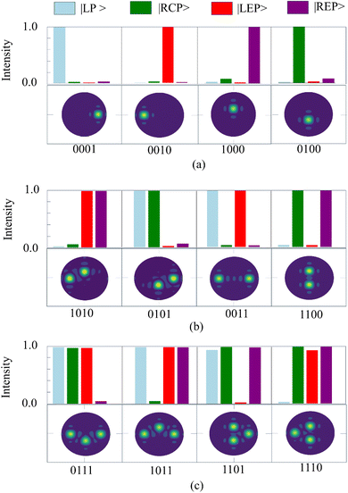
To differentiate between various beam patterns, the binary code “1” signifies the generation of a beam with a specific predefined polarization, while “0” indicates the absence of beam generation. For instance, the code “1111” corresponds to the generation of four beams, whereas “0000” signifies that no beams are generated. The sequence of binary codes, read from right to left, delineates beams characterized by specific polarization states: |LP〉, |LEP〉, |RCP〉, and |REP〉. Fig. 5 illustrates a transition from the generation of a single polarized beam to the creation of three beams, showcasing the intensities and polarization states across all beams. Fig. 5(a) shows the scattering pattern of a single beam channel “0001”, “0010”, “1000”, and “0100” as well as their corresponding polarization intensities. Fig. 5(b) shows the scattering pattern of double beam channels “1010”, “0101”, “0011”, and “1100” as well as their corresponding polarization intensities. Fig. 5(c) shows the scattering pattern of triple beam channels “0111”, “1011”, “1101”, and “1110” and their corresponding polarization intensities. We can observe that the intensity of the polarization states of the different channels matches the target, demonstrating the feasibility of the designed method.
The second step involves achieving the desired amplitude and phase distributions within the polarization channels through temporal signals, enabling free modulation of both. The time-modulated reflection coefficient of the (m,n)-th encoded unit Rmn(t) is a periodic function of time, defined as a linear combination of a series of shifted pulse functions within one period:38
 | (10) |
 | (11) |
 | (12) |
 | (13) |
![[thin space (1/6-em)]](https://www.rsc.org/images/entities/char_2009.gif) exp(jφx) and Ay
exp(jφx) and Ay![[thin space (1/6-em)]](https://www.rsc.org/images/entities/char_2009.gif) exp(jφy).
exp(jφy).
As illustrated in Fig. 6, the complex amplitude and phase distributions of the polarization states for the four beams are determined, leading to the retrieval of corresponding codes from the database. Subsequently, necessary time code sequences for application are generated. The time encoding of the amplitude phase corresponds to the x-polarization for this pattern. Fig. 6(a) and (b) illustrate the temporal encoding of amplitude and phase distributions corresponding to “1111” for x-polarization and y-polarization respectively. Fig. 6(c) and (d) display the normalized intensities of the four different polarization states and the polarization states across the four channels. It can be observed that the intensities of the four polarization states are almost identical. Fig. 6(e) and (f) present the generated 2D far-field patterns for the four spatial beams as well as normalized scattering patterns in the xoz and yoz planes. It can be observed that the four beams are reflected at ±36° and ±16° directions, fulfilling the design requirements. Moreover, the polarization state intensities of the designed beams align with the target and fulfills the requirements.
3.2. THz hologram images at the -1st order harmonic
The spatiotemporal metasurface has the capability to control amplitude and phase at different harmonic frequencies. Here, near-field holographic imaging achieved at the -1st order harmonic supports this functionality. Achieving holographic imaging at the -1st order harmonic involves a systematic approach. Initially, the crucial step is to determine and obtain the necessary amplitude and phase distribution, which are essential for accurate imaging. Subsequently, in the second step, the modulation of amplitude and phase at the -1st order harmonic is achieved through the application of spatiotemporal coding techniques. This ensures that the results align with the theoretical calculations obtained in the initial step, thereby enabling precise holographic imaging.Based on the Huygens–Fresnel imaging principle, the field Ui(x,y,0) on the GSRIS plane can be approximately solved using the given field of a two-dimensional virtual object. This results in the field U(x,y,d) on the imaging plane at Ui(x,y,d), which can be expressed as:
 | (14) |
 and k is wavenumber, U(x,y,d) = U((a − 0.5)Lx/M,(b − 0.5)Lγ/N,d). In eqn (14), the imaging surface with dimensions Lx × Ly is discretized into M × N pixels. Conversely, U(x,y,d) can also be calculated based on Ui(x,y,0):
 | (15) |
Next, the GS algorithm can obtain the required amplitude and phase on the GSRIS array by alternately solving eqn (14) and (15). Specifically, assuming that the designed GSRIS is a perfect reflective array, its reflection amplitude is always set to 0.6. An initial random phase distribution of the array is given. Using eqn (15), the field U(x,y,d) on the imaging plane is calculated. The amplitude of U(x,y,d) is then replaced with the desired amplitude on the imaging plane, and the resulting U(x,y,d) is inserted into eqn (14) to solve the field Ui(x,y,0) on the GSRIS array. The amplitude of Ui(x,y,0) is then replaced with the ideal reflection amplitude of −1.
An initial random phase distribution is assigned to the array. Using eqn (15), the field U(x,y,d) on the imaging plane is calculated. The amplitude of U(x,y,d) is then substituted with the desired amplitude on the imaging plane. This updated field U(x,y,d) is then inserted into eqn (14) to determine the field Ui(x,y,0) on the GSRIS array. Finally, the amplitude of Ui(x,y,0) is replaced with the ideal reflection amplitude of 0.6.
This process is repeated until the calculated image closely matches the desired image on the imaging plane. Here, we perform a theoretical validation for a 100 × 100 array, with the distance d between the metasurface array and the imaging plane set to 4 mm. As shown in Fig. 7(a) and (b), a time-modulated signal is selected with L = 12 to ensure that the desired phase and amplitude levels are achieved. Next, using eqn (14) and (15), the complex amplitude and phase distributions at the -1st harmonic are obtained, as illustrated in Fig. 7(c). The corresponding spatiotemporal coding is derived from this amplitude and phase distribution on the holographic GSRIS array, allowing the achievement of the desired amplitude and phase distribution by applying an appropriate spatiotemporal coding.
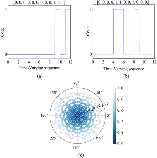 | ||
| Fig. 7 (a and b) The binary codes for the 5th and 200th sequences with L = 12. (c) Complex amplitude distribution at the -1st order harmonic. | ||
Fig. 8 presents the simulated holograms at the -1st order harmonic on an imaging plane, with a central working frequency of 1.3 THz. The phase distribution for the holographic imaging of the letters (“B”, “I”, and “T”) and their corresponding imaging results are shown in Fig. 8. To evaluate the quality of the holographic image, the signal-to-noise ratio (SNR) can be calculated as SNR = 10log10(S/N), where S and N are the sums of the electric field amplitudes in the image region and the remaining region, respectively. The SNRs of the holographic images for the letters “B”, “I”, and “T” are 7.65 dB, 7.55 dB, and 7.24 dB, respectively, indicating that the obtained holographic images have good quality. Based on the amplitude and phase distributions at the -1st order harmonic, the corresponding time-encoded sequences can be obtained from the amplitude and phase distribution database at the -1st order harmonic shown in Fig. 7(c). This result demonstrates that the proposed GSRIS can simultaneously generate multiple holographic images. Therefore, it can be concluded that the designed GSRIS can provide the amplitude and phase control required for holographic imaging, demonstrating the feasibility of the concept.
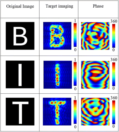 | ||
| Fig. 8 Holographic imaging performance and phase distribution of ‘B,’ ‘I,’ and ‘T’ at the -1st harmonic of the GSRIS. | ||
3.3. Practical aspects of design
Considering that the GSRIS proposed in this paper operates in the THz frequency band and different modulation techniques offer different modulation speed ranges in the THz frequency band, which can impact the system's performance and efficiency. Moreover, diodes are among the most commonly utilized technologies for applications in the gigahertz (GHz) range. However, owing to size limitations imposed by diodes on the minimum dimensions of each meta-atom, they are not suitable for applications at frequencies higher than GHz. Therefore, the electro-tuning of graphene facilitates the development of a rapid and reliable modulation scheme for implementing the proposed time-modulated encoding strategy. Furthermore, a GSRIS was successfully realized using an active radio frequency (RF) bias network, which enables independent addressing and biasing of each grid.As modulation frequency of f0 = 3GHz was selected, as it falls within the practical range. Importantly, by considering the resolution of the terahertz detector, the resulting frequency harmonics can be effectively resolved. The primary challenge lies in selecting the appropriate modulation speed for the current signal system. In this paper, FPGA is employed as the processing module to apply the required time-modulated bias signal to GSRIS units. Furthermore, a review of existing technologies indicates the availability of several high-speed FPGAs capable of generating and designing time-modulated bias signals in the several gigahertz (GHz) range. Consequently, from this perspective, the design of the GSRIS is achievable.
While the results presented in this manuscript are based on full-wave EM simulations, we acknowledge that real-world implementation often presents challenges that may not be fully captured in simulations. As such, we have discussed some of the fabrication techniques and potential difficulties that may arise in the manufacturing process of the proposed graphene spatiotemporal reconfigurable intelligent surface (GSRIS).
The proposed GSRIS is primarily based on graphene, which has become increasingly feasible for fabrication using various methods such as chemical vapor deposition (CVD), laser-assisted chemical etching, and graphene oxide reduction. These techniques enable the production of high-quality graphene sheets that can be integrated with metamaterials or metasurfaces. The integration of graphene with a metasurface structure typically involves the following steps:
High-quality graphene can be synthesized on copper foils via CVD, followed by transfer onto a suitable substrate such as silicon or quartz. The metasurface structure, designed to manipulate EM waves at terahertz frequencies, is typically fabricated using photolithography or electron-beam lithography to create precise patterns on the substrate. Graphene integration: the graphene sheets are transferred onto the patterned metasurfaces. Techniques such as transfer printing or direct growth onto the surface can be used to ensure that the graphene layers are aligned with the metasurface structure. Tuning the chemical potential: to enable dynamic control of the chemical potential in graphene, devices such as field-effect transistors (FETs) or capacitive gating structures may be incorporated to modulate the electric field or voltage applied to graphene, thus adjusting its chemical potential.
While these fabrication techniques have seen success in laboratory environments, several challenges remain in their scaling up to real-world applications, particularly in the context of terahertz-frequency devices: the performance of the GSRIS heavily relies on the quality of graphene. Variations in graphene sheet quality, such as defects or non-uniformity in thickness, can affect the efficiency of polarization control and beam generation. Achieving uniform and high-quality graphene over large areas remains a significant challenge.
The metasurface must be patterned with nanometer-scale precision to effectively manipulate terahertz waves. Lithography techniques such as electron-beam lithography offer high resolution but are expensive and time-consuming. For large-scale production, alternative approaches such as nanoimprint lithography could be explored, although their scalability remains a concern. Integration of components: combining graphene with metasurfaces in a manner that enables seamless modulation of terahertz waves may involve challenges related to material compatibility, electrical contact, and interface quality between graphene and other materials. These integration challenges could affect the long-term stability and efficiency of the device. Because of to the high frequency and power levels involved in terahertz systems, managing heat dissipation in GSRIS devices may become a significant challenge. While the integration of graphene, known for its excellent thermal conductivity, could help alleviate this issue, the overall thermal performance of the device will need to be carefully evaluated.
4. Conclusion
In summary, we simulated a new graphene spatiotemporal reconfigurable intelligent surface (GSRIS) for dynamic terahertz polarization control, multi-beam generation, and holographic imaging. The proposed GSRIS offers strong tunability by applying different chemical potentials to graphene at 1.3 THz, enabling dynamic control of terahertz frequency EM waves. It is important to note that the number of beams and polarization states is not limited to those presented in this paper; they can generally be designed to accommodate different or more complex vector beam patterns. In this study, we demonstrated that terahertz polarization states can be controlled to generate up to four beams, each possessing a distinct polarization state while maintaining exceptional suppression of scattering below −25 dB in all directions. Finally, we showed that the GSRIS demonstrates high-quality terahertz holographic imaging at the -1st harmonic. The SNRs for the holographic images of the letters “B”, “I”, and “T” were found to be 7.65 dB, 7.55 dB, and 7.24 dB, respectively.This technology holds great potential in future research, particularly in the development of adaptive terahertz systems for real-time polarization control and multi-beam generation. The ability to dynamically manipulate terahertz EM waves offers significant advances in imaging, sensing, and communication technologies. For instance, in 6G wireless communication, GSRISs can enable ultra-high-speed data transmission with tailored beamforming and secure communication channels by modulating the polarization state of terahertz waves. Furthermore, GSRIS-based systems could play a key role in intelligent sensing and imaging technologies, such as medical imaging, environmental monitoring, and security applications, by allowing for highly controlled, multi-dimensional beam patterns. Industrial applications can span from secure data encryption to adaptive beam control for radar systems and smart sensors. The reconfigurability and tunability of GSRISs make them a promising candidate for integration into next-generation communication and sensing infrastructures.
Data availability
The data that support the findings of this study are available from the corresponding author upon reasonable request.Conflicts of interest
The authors declare that they have no known competing financial interests or personal relationships that could have appeared to influence the work reported in this paper.Acknowledgements
This research was funded by the National Key R&D Program of China (grant no. 2022YFF0604801), the National Natural Science Foundation of China (grant no. 62271056, 62171186, and 62201037), the Beijing Natural Science Foundation of China-Haidian Original Innovation Joint Fund (grant no. L222042), and the 111 Project of China (grant no. B14010).References
- P. H. Siegel, Terahertz technology in biology and medicine, IEEE Trans. Microwave Theory Tech., 2004, 52(10), 2438–2447 CrossRef.
- S. Nie and I. F. Akyildiz, Channel modeling and analysis of inter-small-satellite links in terahertz band space networks, IEEE Trans. Commun. Syst., 2021, 69(12), 8585–8599 Search PubMed.
- X. Wang, Z. Zhang, Y. Xu, L. Zhang, R. Yan and X. Chen, Real-time terahertz characterization of minor defects by the YOLOX-MSA network, IEEE Trans. Instrum. Meas., 2022, 71, 1–10 Search PubMed.
- C. K. Walker, Terahertz Astronomy, CRC Press, Boca Raton, 2015 Search PubMed.
- S. Helal, H. Sarieddeen, H. Dahrouj, T. Y. Al-Naffouri and M. S. Alouini, Signal processing and machine learning techniques for terahertz sensing: an overview, IEEE Signal Process. Mag., 2022, 39(5), 42–62 Search PubMed.
- Q. Wang, L. Xie and Y. Ying, Overview of imaging methods based on terahertz time-domain spectroscopy, Appl. Spectrosc. Rev., 2022, 57(3), 249–264 CrossRef CAS.
- H. Chen, H. Sarieddeen, T. Ballal, H. Wymeersch, M.-S. Alouini and T. Y. Al-Naffouri, A tutorial on terahertz-band localization for 6G communication systems, IEEE Commun. Surv. Tutor., 2022, 24(3), 1780–1815 Search PubMed.
- Y. Wei, L. Si, L. Dong, Q. Shen, T. Ma, H. Sun and X. Bao, A mid-IR tunable graphene metasurface for ultrasensitive molecular fingerprint retrieval and refractive index sensing, J. Mater. Chem. C, 2023, 11(47), 16501–16508 RSC.
- X. Pang, O. Ozolins, S. Jia, L. Zhang, R. Schatz, A. Udalcovs, V. Borovs, H. Hu, T. Morioka, Y. Sun, J. Chen, S. Lourdudoss, L. Oxenlowe, S. Popov and X. Yu, Bridging the terahertz gap: photonics-assisted free-space communications from the submillimeter-wave to the mid-infrared, J. Lightwave Technol., 2022, 40(10), 3149–3162 Search PubMed.
- P. Gopalan and B. Sensale-Rodriguez, 2D materials for terahertz modulation, Adv. Opt. Mater., 2020, 8(3), 1900550 CrossRef CAS.
- H. Zhang, L. Si, T. Ma, L. Dong, R. Niu, X. Bao, H. Sun and J. Ding, Triple-band terahertz chiral metasurface for spin-selective absorption and reflection phase manipulation, Electronics, 2022, 11(24), 4195 CrossRef.
- W. Xing, L. Si, L. Dong, H. Zhang, T. Ma, H. Sun, X. Bao and J. Ding, Rapid design of hybrid mechanism metasurface with random coding for terahertz dual-band RCS reduction, Opt. Express, 2023, 31(17), 28444–28458 CrossRef PubMed.
- P. Tang, X. Zheng, T. Ma, G. Cheng, G. Wu, X. Bao, H. Sun, J. Ding and L. Si, Terahertz dual-band dual-polarization 3-Bit coding metasurface for multiple vortex beams generation, Electronics, 2023, 12(8), 1868 CrossRef CAS.
- L. Dong, L. Si, H. Xu, Q. Shen, X. Lv, Y. Zhuang and Q. Zhang, Rapid customized design of a conformal optical transparent metamaterial absorber based on the circuit analog optimization method, Opt. Express, 2022, 30(5), 8303–8316 CrossRef PubMed.
- L. Si, Y. Liu, H. D. Lu, H. J. Sun, X. Lv and W. Zhu, Experimental realization of high transmittance THz 90° -bend waveguide using EMXT structure, IEEE Photonics Technol. Lett., 2013, 25(5), 519–522 Search PubMed.
- G. Cheng, L. Si, P. Tang, Y. Zhuang, H. Sun and J. Ding, Topology optimization of the azimuth-rotation-independent polarization conversion metasurface for bandwidth enhancement, Opt. Express, 2022, 30, 41340–41349 CrossRef PubMed.
- A. Samaha, J. Doumani, T. Kritzell, H. Xu, A. Baydin, P. M. Ajayan, M. Tahchi and J. Kono, Graphene terahertz devices for sensing and communication, Small, 2024, 2024, 2401151 CrossRef PubMed.
- Graphene Production and Application, ed S. Ameen, M. Akhtar and H. Shin, Intech Open, London, 2020 Search PubMed.
- A. Singh, M. Andrello, N. Thawdar and J. M. Jornet, Design and operation of a graphene-based plasmonic nano-antenna array for communication in the terahertz band, IEEE J. Sel. Areas Commun., 2020, 38(9), 2104–2117 Search PubMed.
- K. Yuan and L. Ye, Design and simulation of high-efficiency broadband terahertz graphene composite waveguide modulators, IEEE J. Sel. Top. Quantum Electron., 2024, 30(4), 1–9 Search PubMed.
- Y. Plotnik, M. Rechtsman, D. Song, M. Heinrich, J. Zeuner, S. Nolte, Y. Lumer, N. Malkova, J. Xu, A. Szaeit, Z. Chen and M. Segev, Observation of unconventional edge states in ‘photonic graphene, Nat. Mater., 2014, 13, 57–62 CrossRef CAS PubMed.
- A. K. Singh, E. S. Penev and B. I. Yakobson, Armchair or zigzag? A tool for characterizing graphene edge, Comput. Phys. Commun., 2011, 182(3), 804–807 CrossRef CAS.
- P. Ares and K. S. Novoselov, Recent advances in graphene and other 2D materials, Nano Mater. Sci., 2022, 4(1), 3–9 CrossRef CAS.
- Y. Cao, V. Fatemi, S. Fang, K. Watanabe, T. Taniguchi, E. Kaxiras and P. Jarillo-Herrero, Unconventional superconductivity in magic-angle graphene superlattices, Nature, 2018, 556(7699), 43–50 CrossRef CAS.
- Y. Liu, X. Liu, X. Mu, T. Hou, J. Xu, M. D. Renzo and N. AI-Dhahir, Reconfigurable intelligent surfaces: principles and opportunities, IEEE Commun. Surv. Tutor., 2021, 23(3), 1546–1577 Search PubMed.
- N. Ashraf, T. Saeed, H. Taghvaee, S. Abadal, V. Vassiliou, C. Liaskos, A. Pitsillide and M. Lestas, Intelligent beam steering for wireless communication using programmable metasurfaces, IEEE Trans. Intell. Transp. Syst., 2023, 24(5), 4848–4861 Search PubMed.
- Y. Han, X. Li, W. Tang, S. Jin, Q. Cheng and T. J. Cui, Dual-polarized RIS-assisted mobile communications, IEEE Trans. Wirel. Commun., 2022, 21(1), 591–606 Search PubMed.
- Y. Zhuang, L. Si, H. Huang and T. Cai, Highly efficient Airy beam generator with high polarization purity by a receiving-transmitting metasurface, Opt. Express, 2024, 32(18), 31325–31333 CrossRef PubMed.
- L. Si, R. Niu, G. Cheng and W. Zhu, Experimental realization of a transmissive microwave metasurface for dual vector vortex beams generation, Opt. Express, 2024, 32(8), 14892–14903 CrossRef CAS PubMed.
- G. Cheng, L. Si, Q. Shen, R. Niu, Q. Yuan, X. Bao, H. Sun and J. Ding, Transmissive pancharatnam-berry metasurfaces with stable amplitude and precise phase modulations using dartboard discretization configuration, Opt. Express, 2023, 31(19), 30815–30831 CrossRef CAS PubMed.
- F. Faraz, Z. Zhang, Y. Huang, H. Fraz, T. U. R. Abbasi, X. Wang and W. Zhu, Bi-layer reflection-transmission dual-mode metasurface with flexible bandwidth control, Adv. Opt. Mater., 2024, 12(12), 232608 Search PubMed.
- R. Y. Wu, L. Zhang, L. Bao, L. Wu, Q. Ma, G. Bai, H. Wu and T. J. Cui, Digital metasurface with phase code and reflection-transmission amplitude code for flexible full-space electromagnetic manipulations, Adv. Opt. Mater., 2019, 7(8), 1801429 CrossRef.
- L. G. Silva, L. C. Alexandre, P. Xiao and S. A. Cerqueira, RIS development and implementation in a mm-waves 5G-NR system toward 6G, IEEE Wirel. Commun., 2024, 13(3), 736–740 Search PubMed.
- L. M. Si, T. Jiang, K. Chang, T. Chen, X. Lv, L. Ran and H. Xin, Active microwave metamaterials incorporating ideal gain devices, Materials, 2011, 4(1), 73–83 CrossRef CAS PubMed.
- X. Wu, Z. Li, Z. Zhang, X. Wang, L. Si and W. Zhu, Mechanically reconfigurable folded reflectarray antenna for variable near-field focusing, IEEE Trans. Antennas Propag., 2023, 71(12), 10038–10043 Search PubMed.
- E. Arbabi, A. Arbabi, S. Kamali, Y. Horie, M. Faraji-Dana and A. Faraon, MEMS-tunable dielectric metasurface lens, Nat. Commun., 2018, 9(1), 812 CrossRef PubMed.
- C. Pan, H. Ren, K. Wang, J. Kolb, M. Elkashlan, M. Chen, M. Renzo, Y. Hao, J. Wang, A. Swindlehurst, X. Yu and L. Hanzo, Reconfigurable intelligent surfaces for 6G systems: principles, applications, and research directions, IEEE Commun. Mag., 2021, 59(6), 14–20 Search PubMed.
- L. Zhang and T. J. Cui, Space-time-coding digital metasurfaces: principles and applications, Research, 2021, 2021, 9802673 Search PubMed.
- J. Y. Dai, J. Yang, W. Tang, M. Chen, J. Ke, Q. Cheng, S. Jin and T. J. Cui, Arbitrary manipulations of dual harmonics and their wave behaviors based on space-time-coding digital metasurface, Appl. Phys. Rev., 2020, 7(4), 041408 CAS.
- D. L. Sounas and A. Andrea, Non-reciprocal photonics based on time modulation, Nat. Photonics, 2017, 11(13), 774–783 CrossRef CAS.
- L. Zhang, X. Q. Chen, R. W. Shao, J. Y. Dai, Q. Cheng, G. Castaldi, V. Galdi and T. J. Cui, Breaking reciprocity with space-time-coding digital metasurfaces, Adv. Mater., 2019, 31(41), 1904069 CrossRef CAS PubMed.
- Q. Hu, W. Yang, J. Wang, X. Lu, J. Zhao, T. Jiang, K. Chen and Y. J. Feng, Dynamically generating diverse multi-beams with on-demand polarizations through space-time coding metasurface, Adv. Opt. Mater., 2024, 12(6), 2300093 CrossRef CAS.
- F. Yang, T. C. Tan, S. Prakash, A. Kumar, A. Ariando, R. Singh, N. Wang and P. Pitchappa, Reconfigurable wide-angle beam-steering terahertz metasurfaces based on vanadium dioxide, Adv. Opt. Mater., 2024, 12(9), 2002047 Search PubMed.
- H. Li, H. Xu, C. Zheng, J. Liu, J. Li, C. Song, J. Li, F. Yang, W. Shi, Y. Zhang, Y. Zhang and J. Yao, All-silicon diatomic terahertz metasurface with tailorable linear polarization states, Adv. Opt. Mater., 2023, 11(2), 2201960 CrossRef CAS.
- F. Ding, S. Zhong and S. I. Bozhevolnyi, Vanadium dioxide integrated metasurfaces with switchable functionalities at terahertz frequencies, Adv. Opt. Mater., 2018, 6(9), 1701204 CrossRef.
- C. Caloz and Z. L. Deck-Léger, Spacetime metamaterials—part I: general concepts, IEEE Trans. Antennas Propag., 2020, 68(3), 1569–1582 Search PubMed.
- C. Caloz and Z. L. Deck-Léger, Spacetime metamaterials—part II: theory and applications, IEEE Trans. Antennas Propag., 2020, 68(3), 1583–1598 Search PubMed.
- P. C. Tang, L. M. Si, L. Dong, G. Wu, T. Ma, X. Bao and H. Sun, Tunable broadband terahertz graphene metasurface for complex-amplitude vortex beam generator and hologram, Opt Laser. Technol., 2024, 175, 110874 CrossRef CAS.
- W. Zhu, I. D. Rukhlenko, L. M. Si and M. Premaratne, Graphene-enabled tunability of optical fishnet metamaterial, Appl. Phys. Lett., 2013, 102(12), 121911 CrossRef.
- Q. Hu, K. Chen, J. Zhao, S. Dong, T. Jiang and Y. J. Feng, On-demand dynamic polarization meta-transformer, Laser Photonics Rev., 2023, 17(1), 2200479 CrossRef.
| This journal is © The Royal Society of Chemistry 2025 |

