 Open Access Article
A sustainable approach using natural phosphates impregnated with nickel hydroxide nanoparticles: a cost-effective solution for alcohol oxidation'
Sanaa
Chemchoub
a,
Anas
El Attar
a,
Abdessamad
Belgada
a,
Saad Alami
Younssi
a,
Charafeddine
Jama
b,
Fouad
Bentiss
bc and
Mama
El Rhazi
 *a
*a
aUniversity of Hassan II of Casablanca, Faculty of Sciences and Technology, Laboratory of Materials, Membranes and Environment-BP 146, 20650 Mohammedia, Morocco. E-mail: mama.elrhazi@fstm.ac.ma
bUniv. Lille, CNRS, INRAE, Centrale Lille, UMET – Unité Matériaux et Transformations, UMR 8207, F-59000 Lille, France
cLaboratory of Catalysis and Corrosion of Materials, Faculty of Sciences, Chouaib Doukkali University, PO Box 20, M-24000 El Jadida, Morocco
First published on 6th December 2024
Abstract
This study introduces a novel and effective approach for the electrocatalytic oxidation of alcohols, showcasing the development of a highly active and cost-effective anode catalyst for methanol and ethanol. A dual-embedded Ni electrode, named (Ni@NATPhos/Ni), is based on a carbon paste electrode modified with natural phosphate impregnated with nickel ions. A layer of nickel nanoparticles was then added via electrochemical deposition, using a precise combination of wet impregnation and potentiostatic electrodeposition techniques. Characterization using XRD and TEM revealed the formation of crystalline structures such as nickel pyrophosphate (Ni2P2O7) and orthophosphate (Ni3(PO4)2), along with nickel hydroxides (Ni(OH)2), resulting in well-distributed homogenous nickel nanosized particles of approximately 30 nm. The electrocatalytic performance of Ni@NATPhos/Ni was assessed and compared with an unmodified carbon paste electrode in alkaline media. With peak current densities of 110 mA cm−2 for methanol and 83 mA cm−2 for ethanol oxidation, the synthesized catalyst demonstrated significantly improved catalytic efficiency. After 500 CV cycles, the dual-embedded electrode Ni@NATPhos/Ni demonstrated excellent stability, retaining 70.33% and 61.58% of its initial current values for ethanol and methanol, respectively, and exhibiting high tolerance to intermediate species poisoning. Electrochemical impedance spectroscopy (EIS) conducted after stability testing revealed an increase in solution resistance, indicative of the complete oxidation of intermediate species in the alkaline solution. The synthesized Ni@NATPhos/Ni electrode emerges as a promising and robust catalyst for alcohol oxidation reactions, offering significant advancements in electrocatalytic efficiency and stability.
1. Introduction
In response to escalating traditional energy and environmental challenges, researchers are exploring advanced fuel cell technology and hydrogen energy solutions.1 Fuel cells, efficient in converting chemical energy to electrical energy, are pivotal for sustainable resource use and pollution treatment. Two promising approaches, direct alcohol fuel cells (DAFCs) and electrochemical water splitting (EWS), have emerged to address the need for efficient catalysts.2 Palladium (Pd) catalysts are widely used in these applications. In recent studies, Ipadeola K. et al.3–5 emphasized the synthesis and design of palladium-based catalysts for alcohol oxidation. They highlighted the role of morphological control, emphasizing that distinct morphologies contribute to enhanced electrocatalytic CO oxidation. The strategy of combining different metals, such as Au and Pd, showed promising CO oxidation activity. Their studies provide compelling evidence that electrocatalyst performance is intricately linked to size control, composition, morphology, and hetero-atoms, emphasizing the multifaceted nature of catalyst design for superior electrochemical performance.While noble metal catalysts are effective, their scarcity and cost limitations drive the search for alternative, cost-effective catalysts to accelerate the adoption of fuel cells.6
Transition metal oxides and hydroxides have recently received interest to develop economically efficient electrocatalysts that can replace the currently used noble metals in large-scale commercialization of direct alcohol fuel cells.7–9 Nonetheless, the intermediate CO produced during alcohol oxidation continues to be a substantial impediment to their catalytic activity. Therefore, developing a new materials is required to overcome the problem of poisoning and to build more efficient noble-metal free electrocatalysts. It was previously stated that metal oxides may activate the alcohol, allowing it to oxidize the adsorbed carbonaceous intermediate species and therefore free the active site on the surface.10,11 On that basis, nickel-based catalyst materials have been used as electrocatalysts on several occasions, and their strong catalytic activity in the electrochemical oxidation of tiny organic molecules is well known.12–15 Li J. et al.16 innovatively synthesized nickel sulfide nanoparticles (NiS NPs) using an ink precursor method for enhanced electrocatalytic activity in alkaline media for methanol (MOR) and ethanol (EOR) oxidation. The NiS catalyst showed superior performance with high faradaic efficiencies. Wang et al.17 proposed a novel four-six-coordinated nickel hydroxide nanoribbon structure for non-platinum DMFC catalysts, achieving an onset potential of 0.55 V vs. RHE. Li et al.18 explored a cost-effective nickel catalyst for DEFCs, facing challenges in high onset potential.
Moreover, Moroccan natural phosphate as a starting material for catalytic applications is appealing not only because of its distinct physicochemical properties, such as high thermal, mechanical, and chemical stability but also because of its low cost and natural abundance.19,20 Indeed, being the world's leading phosphate producer holding about 75% of the global estimated reserves, Moroccan natural phosphate is a plentiful natural resource and has already been used as a support material specifically for photocatalysis and water treatment applications, and has shown excellent activity with the most effective cost.21,22 Because of their unusual physical/chemical properties and possible usage in electrocatalysis, transition metal combined phosphates have emerged as effective electrode materials and have sparked a lot of academic and technological interest specifically for energy conversion devices perticularly fuel cells.23,24 The study by Xu et al.25 provides insights into the catalytic mechanism of nickel phosphate electrocatalyst for the oxidation of 5-hydroxymethylfurfural to 2,5-furandicarboxylic acid, highlighting the high-valence nickel species/Ni3+ species as the active species. Furthermore, the work by Shao et al.26 emphasizes the role of phosphate groups in improving the oxygen evolution reaction (OER) performance, reinforcing the unique structural feature of edge-sharing CoO9 subunits, which aligns with the facilitative role of phosphate in promoting the oxidation of transition-metal atoms. Their distinctive chemical structure and reactivity for many physicochemical processes, as well as their open framework crystallographic structure, made them a favored catalyst in many catalytic reactions such as the oxidation of high energy-dense organic compounds,27,28 urea,29–31 and alcohols.32–34
The synthesis of electrode materials with rich nanostructural features, such as ultrathin layered materials with controlled size, morphology, composition and most functionalities exposed to the electrolytes, could create abundant electroactive sites and thus improves the catalytic performance.35 In prior studies, various techniques, including the use of surfactants, ligands, and solid membrane templates, were employed to produce nickel phosphate particles with diverse morphologies.36 Li et al. demonstrated a phosphating approach to create a porous Ni2P/Ni combination, exhibiting enhanced chemical bonding and conductivity for urea oxidation compared to NiO/Ni.37 Bai et al. synthesized a trimetallic nickel, copper, and palladium-loaded phosphate catalyst through a microwave-assisted method, showing improved electrocatalytic performance for Ethanol Oxidation Reaction (EOR).38 They found that Ni2P component combined with an appropriate amount of Cu improve EOR efficiency. Their findings highlight the enhanced efficiency of EOR with the Ni2P component and an appropriate amount of Cu. Similarly, Tony and coauthors affirmed that incorporating phosphorous content and nickel into nanoporous Ni–Cu–phosphorous amorphous alloy material enhances the electroactivity of catalysts for methanol oxidation in alkaline solutions.39
In response to the limitations of traditional fuel cell technologies and the need for efficient, sustainable catalysts, this study introduces a novel electrocatalyst for alcohol oxidation based on natural phosphate impregnated with nickel hydroxide nanoparticles. Unlike conventional palladium-based catalysts, which are costly and limited in supply, this catalyst utilizes Moroccan-sourced natural phosphate, an abundant, low-cost material. Synthesis involves an initial wet impregnation, followed by potentiostatic electrodeposition in a 6 mM NiCl2 electrolyte solution at −0.5 V for 45 seconds. Evaluations for ethanol and methanol oxidation in alkaline media (1.0 M NaOH with either 1.0 M ethanol or 1.0 M methanol) reveal enhanced current density peaks and excellent electrocatalytic performance. Notably, after 500 cyclic voltammetry cycles, the catalyst retains 70.33% of its initial activity for ethanol and 61.58% for methanol, with a high Jf/Jb ratio indicating superior resistance to intermediate species poisoning compared to other modified metal oxides and hydroxides. The synthesis, free of surfactants or organic solvents, is scalable and eco-friendly, and physicochemical characterization via XRD, SEM, and TEM confirms a well-defined morphology and robust surface composition. The integration of nickel pyrophosphate nanostructures further enhances electrocatalytic stability and durability, making this catalyst a promising, noble-metal-free candidate for efficient fuel cell applications and a step forward in the development of sustainable energy conversion technologies.
2. Experimental section
2.1. Materials and methods
Sigma-Aldrich provided graphite (powder <20 μm, synthetic, 100%), mineral oil (heavy) (99%), and NiCl2 (97%) sodium hydroxide (NaOH, ≥98%), potassium chloride (KCl, >99%) ethanol and methanol. Solvachim provides hydrochloric acid (HCl, 37 wt%). Natural phosphate was obtained from the Khouribga site in Morocco and processed with diluted HCl as previously described.21All other chemicals used were of analytical reagent grade and were employed as received. Bi-distilled water was utilized for the preparation of all solutions. Scanning Electron Microscopy (SEM) coupled with an energy-dispersive X-ray detector (EDX) Zeiss SUPRA 55-VP and a Panalytical Empyrean diffractometer for X-ray diffraction (XRD) analysis were employed to investigate the composition, morphology, and structural characteristics of the catalyst. X-ray diffraction patterns were recorded over an angular range of 5–90° in (2θ); with a step of 0.05° (2θ) and a counting time of 5 s per step. XRD patterns were recorded and the different diffraction peaks were compared with those available in several databases of the ICDD (International Center for Diffraction Data), using Bruker DIFFRAC.EVA software such as Crystallography Open Data (COD) and Powder Diffraction File (PDF) databases. X-ray photoelectron spectroscopy (XPS) spectra were recorded using the Thermo Scientific K-Alpha XPS system's XPS KRATOS, AXIS Ultra DLD spectrometer. The XPS experimental procedure followed previous descriptions.40 With quantification and simulation of the experimental photo-peaks conducted using CasaXPS software. Quantifications considered a non-linear Shirley background subtraction.41
2.2. Synthesis process of natural pure phosphate impregnanted nickel catalysts
Three electrodes were prepared and tested in this study, their preparation mode is detailed in this section:It is worth mentionning that the mixture in each electrode contains 5 wt% of the active material (natural pure phosphate impregnated nickel (NATPhos@Ni)) and 95% of carbon paste (CP). This percentage was fixed throughout the study after a thorough investigation on the effect of the percentage of the developped composite on the catalytic activity.
2.3. Electrochemical measurements
At room temperature, the electrochemical behavior of the synthesized electrodes (CP@NATPhos/Ni), (CP@Ni@NATPhos) and (CP@Ni@NATPhos/Ni) was evaluated by cyclic voltammetry (CVs), chronoamperometry, and electrochemical impedance spectroscopy (EIS) using a PalmSens4 controlled with the PSTrace 4.6 software. A three-electrode system with the synthesized composites as working electrodes, a platinum wire electrode as an auxiliary electrode, and a silver/silver chloride (Ag/AgCl) as a reference electrode were used to investigate the performance of the synthesized catalyst towards ethanol and methanol oxidation. All electrochemical tests were performed in a solution containing 1 M NaOH with 1 M CH3OH or 1 M C2H5OH. The Electrochemical Impedance Spectroscopy (EIS) was recorded at frequencies ranging from 100 kHz to 100 mHz. The potential range was 0.1 to 1.1 vs. Ag/AgCl for Cyclic Voltammetry (CV) measurements and were performed at a scan rate of 50 mV s−1. Before any measurement all the electrodes were polarized in a solution containing 1 M of NaOH by using cyclic voltametry.3. Results and discussion
3.1. The microstructure and composition of the samples
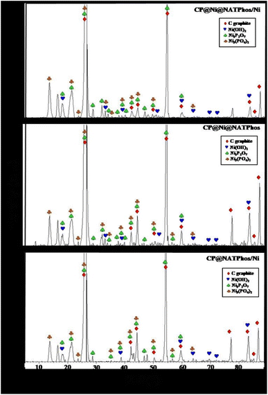
To gain insights into the surface characteristics of the synthesized catalysts and elucidate their crystalline structure, X-ray diffraction (XRD) analysis was performed on CP@NATPhos/Ni, CP@Ni@NATPhos, and CP@Ni@NATPhos/Ni catalysts, as illustrated in Fig. 1. The XRD patterns displayed in Fig. 1 reveal distinctive diffraction peaks corresponding to carbon graphite (JCPDS N0 75-2078), nickel hydroxide Ni(OH)2 (JCPDS N0 73-1520), nickel pyrophosphate Ni2P2O7 (JCPDS N0 74-1604), and nickel orthophosphate Ni3(PO4)2 (JCPDS N0 38-1473). Notably, the diffraction analysis did not detect the presence of nickel phosphide Ni2P, nickel metaphosphate Ni(PO3)2, and nickel oxide NiO in the developed electrodes. This comprehensive examination provides valuable insights into the composition and structural features of the catalysts.Pyrophosphate is a metal phosphate derivatives in which two phosphate tetrahedra (PO34−) share one oxygen atom to generate one pyrophosphate (P2O74−).41 This discovery could imply the production of nickel pyrophosphate in the catalytic matrix as a result of changes in the Ni lattice parameter and its reaction with phosphate tetrahedra originated from the apatite structure present in pure natural phosphate, where two phosphate tetrahedra (PO34−) share one oxygen atom and two Ni2+ atoms to generate one nickel pyrophosphate (Ni2P2O7).
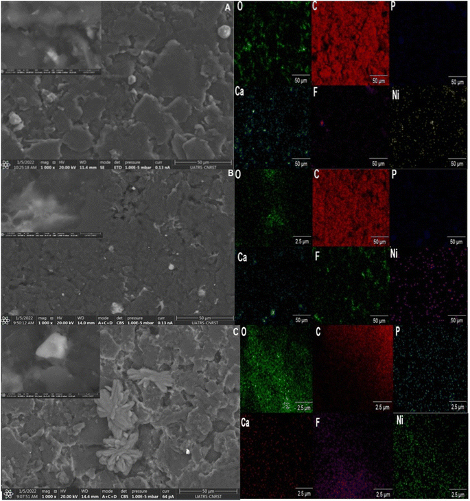
SEM and TEM observations were carried out to determine the morphology and thickness of the prepared catalysts. SEM images of CP@NATPhos/Ni, CP@Ni@NATPhos, and CP@Ni@NATPhos/Ni electrodes are shown in Fig. 2A–C, respectively. For CP@NATPhos/Ni, a well dispersed willow leaves like petals are observed.
A smooth surface of a thick film is observed at CP@Ni@NATPhos. For CP@Ni@NATPhos/Ni, we notice a willow leaves converted into petals which come closer and inter connected. It shows much compact microflower like structure compared to the structure observed at CP@NATPhos/Ni electrode. From the above observations, it seems that the compacity of petals increases as the amount of nickel in the sample augments. Therefore, it can be concluded that the size and shape of the particles are distributed uniformly which allows the crystallite growth and a significantly enlarged surface area. Indeed, Ni(OH)2 deposited from an aqueous solution has a nanoparticle morphology shape with a remarkably homogeneous distribution and size range. These Ni(OH)2 nanoparticles over the elaborated Ni2P2O7 tend to have a superior specific surface area and are anticipated to deliver more reactive sites for electrocatalytic reactions.42 The work by Ahmed et al.,43 demonstrates that the nanoflower structure has electrocatalytic activity for the oxidation of monohydric shorter carbon chain containing alcohols, further supporting the catalytic potential of nanoflower structures.
The EDX mapping of each electrode depicts the emergence of Ni, C, P, F, and O components. It should be noted that CP@Ni@NATPhos/Ni presents a superior nickel distribution.
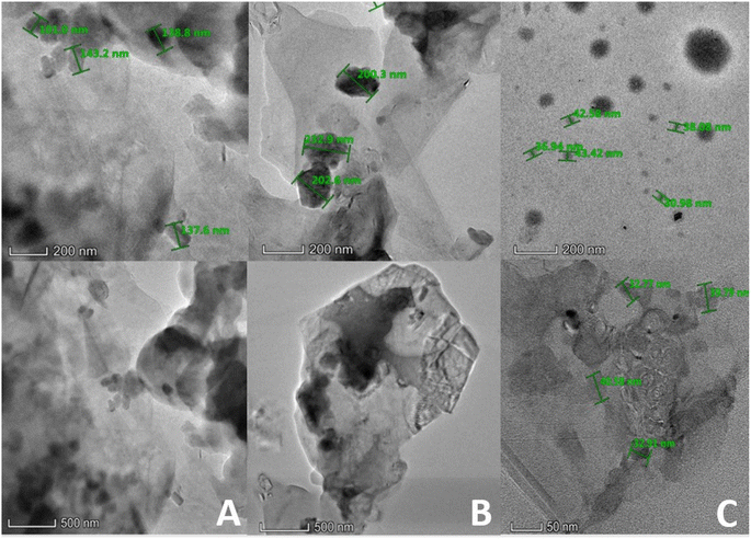
Transmittance Electron Microscopy (TEM) images of CP@NATPhos/Ni, CP@Ni@NATPhos/Ni and CP@Ni@NATPhos as composites with different loading amounts of nickel are depicted in Fig. 3A–C, respectively. The TEM images of CP@Ni@NATPhos/Ni electrode show rounded whitish darkened structures with homogeneous size and shape. CP@NATPhos/Ni and CP@Ni@NATPhos electrodes has visible and larger nanoparticles, and the diameter of the leaf-shaped structures becomes larger, which may be ascribed to the further crystal growth of nickel nanoparticles. It can be found that the average nanoparticle size decreases from 200 to 100, and 30 nm for CP@Ni@NATPhos, CP@NATPhos/Ni, and CP@Ni@NATPhos/Ni, respectively. This decrease is most likely attributed to the creation of more active sites confirming that the nickel thin film supported on the Ni2P2O7 surface is favorable for nanoparticles nucleation.
It is revealed that the Ni nanoparticles exhibit higher dispersity and smaller spherical nanoparticles with the increase in Ni supply. Comparable results were found by Li et al. synthesizing phosphate-intercalated Ni–Ni(OH)2/NiOOH electrode for electrocatalytic oxygen evolution reaction.44 The catalytic activity of nickel pyrophosphate is greatly influenced by particle size reduction.
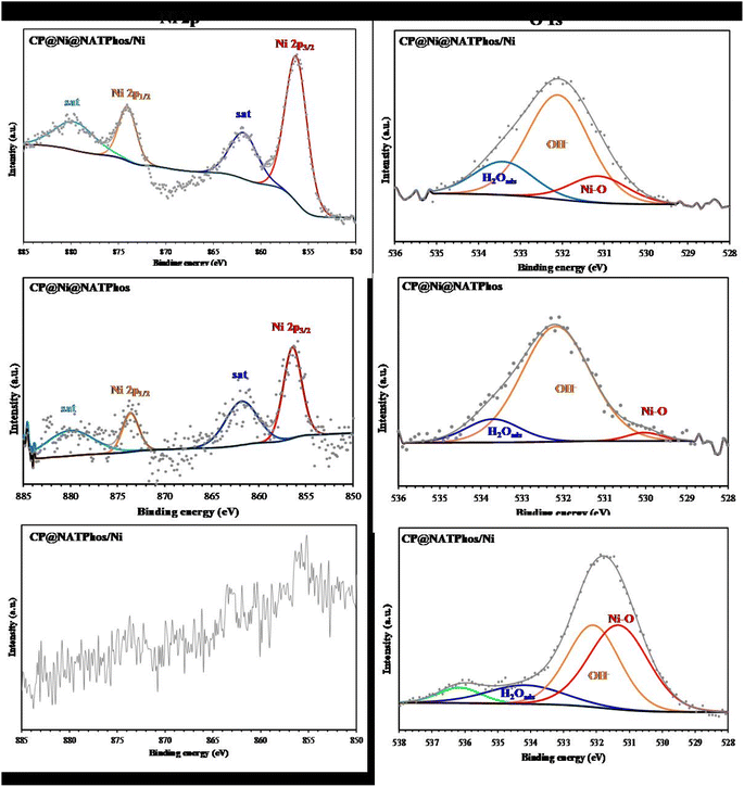
XPS analyses were performed to further explore surface chemical valence state of the synthesized catalysts and the obtained high-resolution peaks for Ni 2p and O 1s core levels, through a deconvoluted fitting procedure using the CASA XPS software, were given in Fig. 4. The obtained values of binding energy (eV) as well as the corresponding quantification (%) for each component were given in Table 1. The P element signal was not detected in the survey spectra (not giving), revealing the non-existence of phosphate phases without and with Ni at the extreme surface (70 nm). The surface analysis from the XPS measurement (Fig. 4) show that the mass percentage of Ni depends of the catalysis nature. Indeed, the Ni (%) value is 0.043 for CP@NATPhos/Ni (A), 0.06 for CP@Ni@NATPhos (B), and 0.31 for CP@Ni@NATPhos/Ni (C). The deconvoluted high-resolution Ni 2p XPS spectra shows two peaks at arround 856 and 874 eV with their respective satellites shakeup at 861 and 880 eV corresponding to the 2p3/2 and 2p1/2 levels (Table 1), respectively.45 A spin–orbital splitting of 18 eV between the peaks and the presence of satellites peaks indicates that presence of Ni2+ species at the investigated catalysts surfaces.46 However, the high-resolution Ni 2p XPS spectrum in the case of CP@Ni@NATPhos/Ni is not distinguishable (Fig. 4), indicating the presence of lower Ni content on the electrode surface. The deconvolution of the high resolution of O 1s XPS spectra for different catalysts showed the presence of peaks related to the Ni–O, OH−, C–O, and H2O groups (Table 1). Indeed, the Ni–O bond and OH− from hydroxide can be associated to the presence of Ni(OH)2 as described in the literature.47
| Catalyst | Ni 2p | O 1s | ||
|---|---|---|---|---|
| BE/eV | Assignment | BE/eV | Assignment | |
| CP@Ni@NATPhos/Ni | 856.3 (48%) | Ni 2p3/2 | 531.1 (16%) | Ni–O/OH− |
| 861.8 (20%) | Satellites shakeup of Ni 2p3/2 | 532.1 (65%) | OH−, C–O | |
| 874.0 (15%) | Ni 2p1/2 | 533.4 (19%) | H2Oads | |
| 879.6 (17%) | Satellites shakeup of Ni 2p1/2 | |||
| CP@Ni@NATPhos | 856.4 (12%) | Ni 2p3/2 | 530.1 (3%) | Ni–O |
| 861.8 (39%) | Satellites shakeup of Ni 2p3/2 | 532.2 (83%) | OH−, C–O | |
| 873.6 (16%) | Ni 2p1/2 | 533.7 (14%) | H2Oads | |
| 880.1 (33%) | Satellites shakeup of Ni 2p1/2 | |||
| CP@NATPhos/Ni | — | — | 531.3 (44%) | Ni–O/OH− |
| — | — | 532.1 (38%) | OH−, C–O | |
| — | — | 534.1 (12%) | H2Oads | |
| — | — | 536.1 (6%) | ||
This study analyzed the structure and composition of three catalysts CP@NATPhos/Ni, CP@Ni@NATPhos, and CP@Ni@NATPhos/Ni using XRD, SEM, TEM, and XPS techniques to understand their suitability for alcohol oxidation. XRD patterns confirmed the presence of nickel hydroxide (Ni(OH)2), nickel pyrophosphate (Ni2P2O7), and nickel orthophosphate (Ni3(PO4)2) in the catalysts, with SEM and TEM images showing compact and well-distributed structures, especially in the dual-embedded electrode CP@Ni@NATPhos/Ni. This catalyst exhibited a microflower-like structure with uniformly dispersed Ni nanoparticles, which increased the active surface area and minimized particle size to about 30 nm, providing more reactive sites. EDX mapping highlighted a superior nickel distribution in CP@Ni@NATPhos/Ni, while XPS data confirmed the presence of Ni2+ species and Ni(OH)2, essential for catalytic activity. Together, these structural features make CP@Ni@NATPhos/Ni a promising, efficient, and durable catalyst for sustainable alcohol oxidation.
3.2. Effect of synthesis procedure on nucleation of nickel nanoparticles
In order to confirm that the impregnation of nickel onto the natural phosphate have an impact on the nucleation process and growth mechanism of the electrodeposited nickel nanoparticles, the number of nuclei as well as the diffusion factor for both electrodes Ni@NATPhos/Ni and NATPhos/Ni are calculated using the following eqn (1) and (2) respectively.| N0 = 0.065 (8πCM/ρ)−1/2(nFC/imaxtmax)2 | (1) |
| D = imax2tmax/0.1629 (nFC)2 | (2) |
Kinetic parameters are calculated from the currents transients (Fig. 5) using Scharifker–Hills theoretical model approach48,49 as shown in Table 2.
 | ||
| Fig. 5 Electrodeposition of the nickel nanoparticles at E = −0.5 V for 45 s: (a) Ni@NATPhos/Ni and (b) NATPhos/Ni. | ||
| Electrode | −imax (mA cm−2) | t max (s) | D (cm2 s−1) | N 0 (cm−2) |
|---|---|---|---|---|
| Phos/Ni | 2.537 | 0.1 | 2.946 10−6 | 1.36 106 |
| Ni@Phos/Ni | 0.9094 | 0.1 | 3.785 10−7 | 1.06 107 |
As can be seen, from the Table 2, a significant change in N0, D, imax and tmax were observed. As explained in the literature, the increase of number of nuclei is due to the active surface of electrode which leads to high number of active nucleation site,50 or to the existence of energies distribution on the surface of electrode with a larger fraction of site becoming active. In our case, we can explain the increase in the numbers of nuclei (N0) by the change in surface conductivity of the electrode due to the incorporation of nickel pyrrophosphate.
3.3. Electrochemical behavior of the synthesized composites in alkaline media
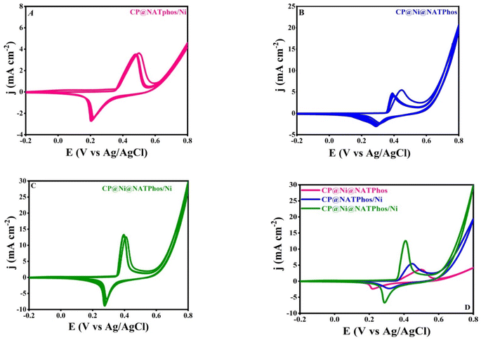
Cyclic voltammetry technique was used to assess the electrochemical characteristics of the generated electrocatalysts in an alkaline solution, all the measurement were performed between −0.2 to 0.8 V vs. Ag/AgCl for 10 cycles using different carbon paste modified electrodes (CP@NATPhos/Ni, CP@Ni@NATPhos and CP@Ni@NATPhos/Ni).Fig. 6(A–C) shows cyclic voltammograms obtained with CP@NATPhos/Ni, CP@Ni@NATPhos, and CP@Ni@NATPhos/Ni respectively done at a scan rate of 50 mV s−1 for 10 cycles in a solution containing 1 M NaOH solution. The last cycle for each electrode is compared in Fig. 6D.
For all the synthesized catalysts, a well defined anodic and cathodic peaks are observed due to the interaction of Ni+2 and Ni+3 rising from the nickel nanoparticles loaded on natural pure phosphate, the CV curves feature a pair of significant redox peaks. The peaks represent the oxidation of Ni(OH)2 to nickel oxy-hydroxide [NiOOH] in the anodic run and the reduction of the produced oxy-hydroxide to Ni(OH)2 in the cathodic half cycle respectively as follows:
| NiOOH + H2O + e− ↔ Ni(OH)2 + OH− |
The continuous activation of the electrodes in alkaline media results in more Ni2+/Ni3+ active species on the surface of the composite, which explains the increase in peak current. Similar behavior was found by Hassan and coworkers using Ni-metal oxide (Fe2O3, ZnO, Co3O4 and MnO2) nanocomposites in an electrolyte aqueous solution containing 1 M NaOH.51 Their behavior in alkaline media has been found critical in enhancing the electro–catalytic activity towards alcohol oxidation. The Ni2+/Ni3+ redox couple's creation is a well-known phenomenon for all developped nickel-based electrocatalysts.52Table 3 summarizes the current densities and the potentials of anodic and cathodic peaks of the elaborated catalyst extracted from Fig. 6D.
| Catalysts | J a (mA cm−2) | J c (mA cm−2) | E a (V) | E c (V) | ΔEp (V) |
|---|---|---|---|---|---|
| CP@NATPhos/Ni | 5.44 | −2.26 | 0.448 | 0.313 | 0.175 |
| CP@Ni@NATPhos | 3.5 | −2.33 | 0.5 | 0.216 | 0.284 |
| CP@Ni@NATPhos/Ni | 13 | −6.67 | 0.408 | 0.289 | 0.119 |
The redox peaks of all catalysts appear at potentials of +0.5, +0.448 and +0.408 V vs. Ag/AgCl in the anodic direction for CP@Ni@NATPhos, CP@NATPhos/Ni, and CP@Ni@NATPhos/Ni, respectively. Whereas, the cathodic peaks are shifted to the less negative direction. However, when compared to CP@Ni@NATPhos electrode, the current densities for the redox peaks in CP@Ni@NATPhos/Ni electrode is substantially higher. Indeed as depicted in Fig. 6D, the current density is found to be 13 mA cm−2 (curve a) higher than that of the CP@NATPhos/Ni (curve b, 5.4 mA cm−2) and CP@Ni@NATPhos (curve c, 3.5 mA cm−2) electrodes. All in all, CP@Ni@NATPhos/Ni exhibits the highest current density of redox peaks and a decrease between the anodic and cathodic peaks (ΔEp) from 0.28 to 0.12 V vs. Ag/AgCl. Indeed, to achieve a current density of 13 mA cm−2, the CP@Ni@NATPhos/Ni electrode requires an overpotential of 0.4 V vs. Ag/AgCl, which is lower than those of CP@NATPhos/Ni (0.43 V vs. Ag/AgCl) and CP@Ni@NATPhos (0.49 V vs. Ag/AgCl).
Electrochemical Impedance Spectroscopy (EIS) was carried out to further evaluate the electrochemical behavior of the synthesized catalyst in alkaline media and to asses their charge transfer. The Nyquist plots of EIS spectra for CP@NATPhos/Ni, CP@Ni@NATPhos and CP@Ni@NATPhos/Ni electrodes in 1 M NaOH solution at 0.4 V vs. Ag/AgCl applied potential in the frequency range between 100 kHz to 0.1 Hz are shown in Fig. 7A–C. In general, all curves include two components: a semicircle and a straight line, which are corresponded to the charge transfer limitation process at high frequency and the diffusion process at low frequency, respectively.
 | ||
| Fig. 7 Nyquist plots of CP@NATPhos/Ni (A), CP@Ni@NATPhos (B), CP@Ni@NATPhos/Ni (C) electrodes in 1 M NaOH solution (inset: fitting equivalent circuit). | ||
As can be seen in the Fig. 7, the semicircle shape of the Nyquist plots of the EIS spectra for CP@NATPhos/Ni and CP@Ni@NATPhos/Ni catalysts (Fig. 7A and C) was distinctive from that of the CP@Ni@NATPhos and suggested the development of nanostructured thin films on the surface of electrodes probably due the electrochemical deposition of nickel nanoparticles. The semicircle's diameter corresponding to the charge resistance transfer should be as narrow as possible for the best electrochemical activity. The EIS results are summarized in Table 4.
| Catalysts | R ct (mΩ) | C f (μF) |
|---|---|---|
| CP@Ni@NATPhos | 131.30 | 0.013 |
| CP@NATPhos/Ni | 20.92 | 659.6 |
| CP@Ni@NATPhos/Ni | 6.478 | 736.9 |
Based on the presented results, it can be noted that the charge resistance transfer (Rct) follows the trend as: CP@Ni@NATPhos exhibiting a higher value than CP@NATPhos/Ni, which, in turn, is higher than that of CP@Ni@NATPhos/Ni. This suggests that the electrodeposited thin film of nickel on the natural phosphate-impregnated nickel catalysts exhibits the lowest electrochemical charge transfer resistance. Specifically, the electrodeposited nickel nanoparticles facilitate easier electron transfer and enhanced conductivity due to their thinner thickness and finer particle size. Conversely, the CP@Ni@NATPhos/Ni electrode demonstrates the highest capacitance (Cf) at 736.9 μF. The reduction in Rct value and the increase in Cf at the electrode/electrolyte interface of CP@Ni@NATPhos/Ni indicate enhanced charge transfer and electron flow. These findings align with the cyclic voltammetry data (Fig. 6). Similar behavior has been reported by Liu et al. in their study using nickel oxides-based electrocatalyst for the reduction of imidacloprid in alkaline media.53
Recent investigations reported that the phosphate group can facilitate the oxidation of transition-metal atoms during the proton coupled electron transfer process.54 Usually, the phosphate group exists in three different species (PO43−, P2O74−, and P3O105−) according to the surrounding pH value.55 It has been suggested that the usage of pyrrophosphate (P2O74−) promotes facile Ni oxidation and high chemical stability, which overall is beneficial for electrochemical applications. This process could benefit the electrochemical performance, especially for Ni based electrodes.56 Souza et al.57 reported the synthesis of structured nickel pyrrophosphate (Ni2P2O7) combined with graphene nanoribbon by a simple precipitation method, the proposed hybrid material was found to provide remarkably improved properties including easy charge transfer, high electroactive surface area and high activity in alkaline medium. The combination of highly dispersed Ni2P2O7 in direct contact with graphene ensured some enrichment of Ni in the catalyst, contributed toward the production of an efficient material in alkaline conditions. On this basis, we suppose that the enhanced electrochemical features of CP@Ni@NATPhos/Ni electrode might be explained by the following assumption: The increased interaction between the electrodeposited nickel thin film and the natural pure phosphate impregnated nickel particles (nickel pyrrophosphate Ni2P2O7) synthesized through the wet impregnation of nickel in natural pure phosphate Ni@NATPhos allowing a higher dispersion of Ni nanoparticles creating more electrochemically active nickel species. Consequently, the addition of electrodeposited nickel thin film improves the electrical wiring of the composite via percolation through the Ni@NATPhos (Ni2P2O7) active material, resulting in improved electrical contact and thus an easier electron transfer. Nivetha et al.58 and Ulu et al.59 highlighted the potential of Ni2P2O7 thin film electrodes in advancing energy storage and conversion technologies. Their studies were mainly oriented towards exploring the viability of transition metal phosphates, specifically Ni2P2O7, as electrode materials for supercapacitors.
The objective of this study is to assess the electrochemical performance of the three modified carbon paste electrodes (CP@NATPhos/Ni, CP@Ni@NATPhos, and CP@Ni@NATPhos/Ni) through cyclic voltammetry (CV) and electrochemical impedance spectroscopy (EIS) in alkaline media (1 M NaOH). The CV analysis reveals distinct redox peaks associated with the Ni2+/Ni3+ redox couple, with CP@Ni@NATPhos/Ni exhibiting the highest current density, achieving 13 mA cm−2 at an overpotential of 0.4 V vs. Ag/AgCl significantly lower than that required for CP@NATPhos/Ni (0.43 V) and CP@Ni@NATPhos (0.49 V). This lower overpotential indicates enhanced electrocatalytic activity, further confirmed by the narrower separation between anodic and cathodic peaks (ΔEp), reduced from 0.28 to 0.12 V, underscoring improved electron transfer kinetics. In EIS analysis, conducted in the same alkaline medium at an applied potential of 0.4 V vs. Ag/AgCl over a frequency range of 100 kHz to 0.1 Hz, the Nyquist plots indicate that CP@Ni@NATPhos/Ni exhibits the lowest charge transfer resistance (Rct) of 6.478 Ω and a high capacitance (Cf) of 736.9 μF, indicating increased electroactive surface area and electron flow efficiency at the electrode/electrolyte interface. These combined properties lower Rct, higher Cf, and enhanced current density suggest that CP@Ni@NATPhos/Ni is a promising candidate for efficient alcohol oxidation reactions in alkaline fuel cell applications, advancing the development of noble-metal-free catalysts for sustainable energy conversion.
3.4. Electrocatalytic performance of the elaborated catalysts towards ethanol and methanol oxidation
The electrocatalytic activity and stability towards methanol and ethanol oxidation over the surface of the developped natural phosphate incorporated nickel nanoparticles are scrutinized in this section. In an alkaline medium, we performed similar studies with unmodified carbon paste electrodes (CPE) and natural pure phosphate impregnated nickel nanoparticles electrodes for comparison. Fig. 8 depicts the CV curves of CP@Ni@NATPhos/Ni, CP@Ni@NATPhos, CP@NATPhos/Ni, and bare carbon paste electrode (CPE) in 1 M NaOH containing 1 M methanol (A) or 1 M ethanol (B) at a scan rate of 50 mV s−1. Table 5 summarizes all the results obtained in terms of current densities and potential peaks.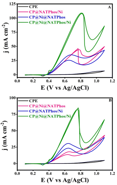 | ||
| Fig. 8 CVs of catalysts of natural phosphate incorporated nickel nanoparticles in 1 M NaOH solution containing (A) 1 M CH3OH, (B) 1 M C2H5OH. | ||
| Catalysts | E a (V) | I a (mA cm−2) | E a (V) | I a (mA cm−2) |
|---|---|---|---|---|
| Methanol | Ethanol | |||
| CPE | 0.7 | 0.6 | 0.65 | 0.17 |
| CP@Ni@NATPhos | 0.7 | 34.75 | 0.64 | 17.85 |
| CP@NATPhos/Ni | 0.77 | 44.23 | 0.63 | 30.63 |
| CP@Ni@NATPhos/Ni | 0.81 | 110.7 | 0.75 | 83.4 |
As can be seen from Fig. 8 and the Table 5, a considerable raise in current density at 0.4 V vs. Ag/AgCl in the forward scan occurs as soon as the alcohol molecule is added to the alkaline solution. CP@NATPhos/Ni and CP@Ni@NATPhos show lower electrocatalytic activity towards both methanol and ethanol, whereas bare carbon paste electrode doesn't present any catalytic activity whatsoever. It is then established that the presence of nickel species in natural pure phosphate is mandatory for methanol and ethanol oxidation. The addition of thin film of nickel on CP@Ni@NATPhos/Ni enhances tremendously the anodic peak current. The current at the CP@Ni@NATPhos/Ni electrode reaches 110 mA cm−2 for methanol and 83 mA cm−2 for ethanol. Similar observations were reported by Song et al. suggesting that the high content of nickel phosphate on the electrode surface profitably enhances methanol oxidation reaction activity of the electrocatalyst.60 In fact, even though natural pure phosphate is a nonconductive material, it has enough surface area to allow electrolytes to diffuse and cations to exchange.61 The oxidation of alcohol begins (onset potential) at the redox couple's peak potential, showing that the hydroxide redox couple is effectively involved in the process. The presence of natural pure phosphate impregnated nickel oxide in the matrix of the electrodeposited nickel causes a substantial number of Ni(II) species transformed into Ni(III), and subsequently the creation of additional oxygen and more active sites available for electrocatalytic oxidation of ethanol and methanol.
We suggest that the elaborated nickel pyrophosphate structure incorporated on graphite carbon acts as a barrier, prevents the electrodeposited Ni(OH)2 thin film agglomeration, and as a result, reduces the particle size and increase the surface area which lead to an enhancement of the catalytic performance of CP@NATPhos@Ni/Ni. The catalytic activity of nickel is greatly influenced by particle size reduction. These findings are in perfect accordance with the results obtained by TEM and SEM analyses.
3.5. Electrochemical impedance spectroscopy (EIS)
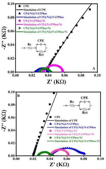
The surface charge transfer performance of the synthesized catalysts towards ethanol and methanol electrooxidation can be evaluated using electrochemical impedance spectroscopy (EIS). Nyquist plots of CP@Ni@NATPhos/Ni, CP@NATPhos/Ni, CP@Ni@NATPhos and bare carbon paste catalysts for the electrochemical oxidation of alcohol in 1 M NaOH at a potential of 0.5 V and a amplitude of 10 mV were performed, ten points per decade were collected in a frequency range of 100 kHz to 100 mHz. The results obtained are shown in Fig. 9 for methanol (A) and ethanol (B). Adjusting the Nyquist plots yielded an equivalent electrical circuit represented as a whole line. The charge transfer resistance (Rct) between electrode and electrolyte is represented by the diameter of the semicircle. The charge transfer resistance (Rct) and the capacity of the film (Cf) were determined by fitting impedance data using the Randles equivalent circuit. Table 6 summarizes the results of the simulation. The smallest Rct (14.39 Ω for methanol and 16.63 Ω for ethanol) along with the highest Cf (312.98 μF for methanol and 394.58 μF for ethanol) at CP@Ni@NATPhos/Ni electrode suggested a high electron transfer efficiency and a low charge transfer resistance for the investigated electrocatalysts resulting in increased conductivity and an increased electrocatalytic activity. The lowest Rct confirms that CP@Ni@NATPhos/Ni is the optimum electrocatalyst for improving methanol or ethanol catalytic oxidation.33,39,62| Catalysts | R ct (Ω) | C f (μF) | R ct (Ω) | C f (μF) |
|---|---|---|---|---|
| Methanol | Ethanol | |||
| CPE | 1619 | 17 | 2917 | 13.60 |
| CP@Ni@NATPhos | 24.4 | 164.7 | 48 | 147.1 |
| CP@NATPhos/Ni | 16.7 | 278.80 | 22 | 274.3 |
| CP@Ni@NATPhos/Ni | 14.4 | 313 | 16.6 | 394.6 |
For methanol, CP@Ni@NATPhos/Ni, CP@NATPhos/Ni, CP@Ni@NATPhos and unmodified carbon paste (CPE) had Rct values of 14.39 Ω, 16.73 Ω, 24.42 Ω and 1619 Ω respectively. The lowest resistance charge transfer indicates a faster methanol electro-oxidation reaction. The same goes for ethanol with the following charge resistance transfer values: 2917 Ω, 41.97 Ω, 21.95 Ω, and 16.63 Ω, for CPE, CP@Ni@NATPhos, CP@NATPhos/Ni, and CP@Ni@NATPhos/Ni, respectively.
As stated earlier, the reduction of nanoparticle aggregation may have resulted in more nanoparticles being disseminated uniformly on the nickel pyrophosphate structure, results in more accessible active sites and highest surface area, which is compatible with the good dispersibility of nanoparticles seen in TEM. As a result, the measured impedance data backs up the catalytic activity evaluated based on the CV analysis. The Rct values of CP@Ni@NATPhos/Ni in both ethanol and methanol are reduced when the nickel thin film is electrodeposited on the nickel impregnated natural phosphate. However, for the same catalyst, the Rct of is roughly similar for both methanol and ethanol, implying that the CP@Ni@NATPhos/Ni electrode has a good electro-transfer kinetics for alcohol oxidation.
3.6. Effect of alcohol concentration
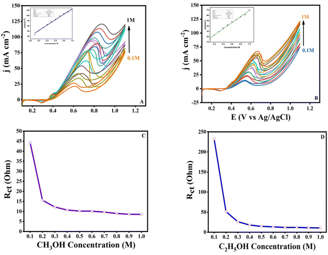
We investigated the influence of methanol and ethanol concentration on the catalytic activity of the produced electrocatalyst CP@Ni@NATPhos/Ni in 1 M NaOH solution with a range of concentrations from 0.1 M to 1 M. Fig. 10 shows the relationship between anodic peak current density of methanol and ethanol concentrations at the prepared electrocatalyst. It is obvious that the CV response graphs indicate the increase of the anodic oxidation current density with the increase of alcohol concentration and show a linear relationship with the concentration while the correlation coefficient is found to be 0.985 for methanol (Fig. 10A) and 0.992 for ethanol (Fig. 10B). Ethanol and methanol molecules reacts effectively with each and every available active site on the catalyst at higher concentrations. The increase in the oxidation current density demonstrates the excellent catalytic activity of the catalyst. At higher alcohol concentrations, the concentration of the non-oxidized residues increases which requires a higher positive potential this is highly likely due to the adsorption of intermediates on remaining active sites, which prevents further oxidation of ethanol and methanol. The created CP@Ni@NATPhos/Ni electrode has a good catalytic performance for electro-oxidation of high concentrations of ethanol and methanol as compared to other nanomaterials reported in the literature.63–65One of the most important parameters of an electrocatalyst is the charge transfer resistance (Rct). Electrochemical impedance spectroscopy was conducted in the same experimental conditions to investigate the variation of the charge resistance transfer (Rct) of the synthesized catalyst with the concentration of methanol (Fig. 10C) and ethanol (Fig. 10D). It can be noticed that within the concentrations ranging from 0.1 to 1 M, a steady decrease in the Rct was observed. A first abrupt decline from 45 Ω to 15 Ω and from 244 Ω to 50 Ω for methanol and ethanol, respectively, which gives way to a very gradual change. This observation supports the theory that alcohol concentration influences the charge transfer and reflects the improved charge transfer of the electrocatalyst, where the charge transfer resistance is the lowest.66,67
3.7. Stability and durability of the catalysts
One of the most essential parameter keys for evaluating the electrode's electrocatalytic performance is its long-term stability. The chronoamperometric analysis for the synthesized catalysts was carried out in the presence of 1.0 M methanol (Fig. 11A) and 1.0 M ethanol (Fig. 11B) obtained at 0.5 V vs. Ag/AgCl for 1000 s. All samples clearly indicate current degradation in the initial seconds before reaching a relative steady state. The adsorption of some incomplete oxidation products on the electrode surface is most likely to cause this degradation.68 Furthermore, the initial drop can be attributable to the rapid oxidation of methanol or ethanol molecules near the electrode surface. The CP@Ni@NATPhos/Ni catalyst exhibited an initial current density higher than those of CP@NATPhos/Ni and CP@Ni@NATPhos, respectively, suggesting its noteworthy electrocatalytic activity. The natural pure phosphate allows the creation of cavities in the pyrophosphate material which makes ion and alcohol molecule transport easier.69,70 This is also attributable to the electrodeposited nickel thin film promoting the oxidation of the adsorbed carbonaceous accumulation species and increasing the capacity of the hydroxyl ion to adsorb onto the catalyst surface.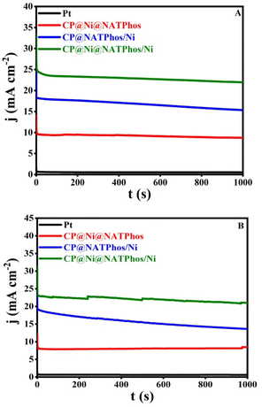 | ||
| Fig. 11 Chronoamperometry of different elaborated catalysts in 1 M NaOH + 1 M methanol (A) and 1 M ethanol (B) working potential: +0.5 V vs. Ag/AgCl. | ||
It is worth mentionning that the current density of CP@Ni@NATPhos/Ni is approximately 25-folds that of platinum electrode, demonstrating it highest stability and efficiency. The most significant barriers to the commercialization of DAFCs is the stability of anode catalysts for long-term operation. It is then vital to investigate the cycling stability of the prepared catalyst. Its ability to withstand poisoning by carbonaceous intermediates during alcohol oxidation is a mandatory requirement. To evaluate the durability of the synthesized catalyst, 500 consecutive cycles were performed over at a scan rate of 100 mV s−1 in 1 M NaOH + 1 M CH3OH (Fig. 12A) and 1 M NaOH + 1 M C2H5OH (Fig. 12B).
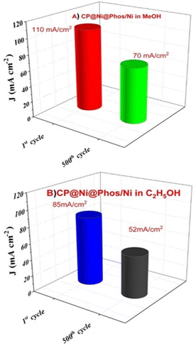 | ||
| Fig. 12 The first and 500th scans for CP@Ni@Phos/Ni in (A) 1 M NaOH + 1 M CH3OH solution, (B) CP@Ni@Phos/Ni after 500 cycles in 1 M NaOH + 1 M C2H5OH solutions. | ||
After 500 cycles, the CP@Ni@NATPhos/Ni catalyst presents a small decrease in current density, it retains 70.33% and 61.68% of its initial value for methanol and ethanol, respectively (Fig. 13). The explanation of this drop is that after several cycles, by-products from the methanol and ethanol oxidation process accumulate on the electrode surface, preventing their free passage and contact with the catalyst. It was previously discussed that the intermediate CO produced during alcohol oxidation continues to be a substantial impediment to the catalysts' performance. This intermediate molecule occupied the active sites of the catalysts that were available slowing down the reaction rate. The current density may be deteriorated throughout the reaction process with the consumption of ethanol and methanol around the electrode surface. Comparable results were found by Roodbari J. et al. using an electrocatalysts based Ni–Co/GO–TiO2 composite catalysts for electrooxidation of methanol and ethanol in alkaline media.68
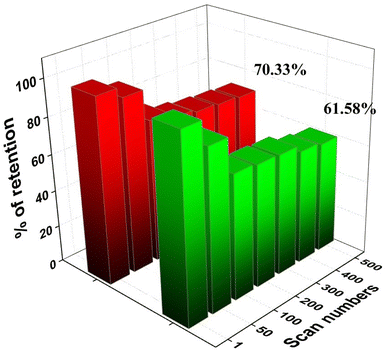 | ||
| Fig. 13 Variation of forward peak current density of CP@Ni@NATPhos/Ni catalyst versus cycle numbers in 1 M NaOH for ethanol and methanol. | ||
In our case, the low electrical resistance of nickel and pure phosphate in the elaborated crystalline phase of Ni2P2O7, along with the carbon support, results in electrical conductivity, which may aid catalytic kinetics and increase CO tolerance. More precisely, it facilitates the dispersion of the electrodeposited nickel thin film and reduces the particles aggregation. As a result, methanol and ethanol adsorption process on the Ni(OH)2 nanoparticles is extremely facilitated which improves electron transfer and reduces CO poisoning by increasing hydroxyl ion adsorption on the catalyst surface. Additionally, it facilitates the oxidation of CO to CO2via the activation of water in an adjacent site.68,71–73 In the electrocatalytic oxidation of methanol and ethanol, the proposed mechanisms shed light on the intricate processes occurring at the electrode interface. For methanol, a Ni-based electrode facilitates the oxidation process in an alkaline medium, following the reaction NiOOH + methanol → Ni(OH)2 + products.
Throughout the methanol oxidation reaction (MOR), intermediate species such as formate, formaldehyde, and carbonate are generated, with formaldehyde serving as an active intermediate species for further oxidation. The proposed mechanism for primary alcohol oxidation involves the formation of Ni(OH)2 + RCH2OH, leading to the production of RC-HOH, which, upon interaction with hydroxide ions, results in the formation of RCOOH, H2O, and electrons.
Similarly, ethanol oxidation is explored through two distinct pathways denoted as C1 and C2. In both cases, ethanol is initially adsorbed on the electrocatalyst surface to form an adsorbed intermediate (CxHyOHad). The first pathway involves the direct oxidation of the adsorbed intermediate to COad, further oxidized to the final product CO2. The ultimate products of the second pathway are acetic acid (CH3COOH) and acetaldehyde (CH3CHO), which have the ability to be further oxidised to CO2. Those mechanisms have been explained extensively in our previous papers.74–76
This section evaluates the electrocatalytic activity of nickel nanoparticles incorporated into natural phosphate for methanol and ethanol oxidation in 1 M NaOH. Compared to unmodified carbon paste electrodes, the CP@Ni@NATPhos/Ni catalyst demonstrates significantly enhanced activity, achieving high current densities of 110 mA cm−2 for methanol and 83 mA cm−2 for ethanol. Electrochemical impedance spectroscopy (EIS) reveals that CP@Ni@NATPhos/Ni exhibits the lowest charge transfer resistance (Rct), reflecting efficient electron transfer and improved conductivity. Additionally, increased alcohol concentrations correlate with higher anodic peak currents, indicating a proportional relationship between substrate concentration and catalytic activity up to a saturation threshold. Stability tests further confirm the catalyst's durability, as it retains over 60% of its initial activity after 500 cycles in both ethanol and methanol, while other catalysts degrade more rapidly under similar conditions. This enhanced performance is attributed to the presence of defects in the natural phosphate matrix and the minor incorporation of nickel, which together improve the electroactive surface area, prevent nanoparticle agglomeration, and facilitate active Ni(II) to Ni(III) transitions. These structural and compositional features generate additional reactive sites, making CP@Ni@NATPhos/Ni a promising candidate for efficient alcohol oxidation in alkaline fuel cells.
To compare our results with existing literature, Table 7 presents the catalytic performances of our electrocatalysts in comparison to other composites from various studies. The electrocatalysts demonstrate notable long-term stability and effective electrochemical activity for both MOR and EOR.
| Catalyst | Synthesis method | Morphology | Electrode substrate | Measurement conditions | Anodic peak current density | Anodic peak potential | I a/Ic | Stability | Ref. |
|---|---|---|---|---|---|---|---|---|---|
| Pd@NP/VC | Wet chemical method | Nanoparticles | GCE | 0.5 M MeOH/0.5 M EtOH | 800 mA mg−1 | 0 V/NHE | 0.82 | 76% of current retention after 500 cycles (CV) | 77 |
| 0.5 KOH, at 50 mV s−1 | 1.42 | ||||||||
| Pt@ZnO | Atomic layer deposition/hydrothermal synthesis | Nanorod/carbon nanofiber | Pt | 0.5 M H2SO4 + alcohol | 40 mA cm−2 | 0.5 V/SCE | — | 1800 s | 78 |
| NiCuCo2O4/MesoZ | Ions exchange method | Nanorod | GCE | 0.5 M MeOH + 1 M NaOH, at 50 mV s−1 | 27 mA cm−2 | 0.6 V/Ag/AgCl | — | 98% of current retention after 1000 cycle | 79 |
| Ni/ANA zeolite | Hydrothermal synthesis | Particles | CPE | 0.02 M MeOH + 0.1 M NaOH, at 20 mV s−1 | 9 mA cm−2 | 0.75 V/Ag/AgCl | — | — | 80 |
| Ni@3DHPG | Cation exchange | Macro and sub-microporous structures | GCE | 1 M KOH + 0.2 M MeOH | 120 mA cm−2 | 0.77 V/Ag/AgCl | — | Minor change after 3000 s | 81 |
| Resin-assisted strategy | |||||||||
| Ni9S8@C | One-pot synthesis | Nanoparticles | GCE | 1 M KOH + 0.5 M CH3OH | 55 mA cm−2 | 1.7 V vs. RHE | — | Minor change after 5000 s | 82 |
| Nickel phosphate | Precipitation method | Particles | GCE | 0.5 M NaOH + 3 M EtOH | 800 μA cm−2 | 0.75 V vs. AgAgCl | — | Loss of 8.97% after 1000 cycles | 62 |
| GNiPy350N | Precipitation method | Nanoarticles | GCE | 1 M KOH for OER | — | 1.55 V vs. RHE | — | 10 mA cm−2 after long-term stability test | 57 |
| Ni aerogel | Electroless plating | Nanofilm | GCE | 1 M KOH + | 28 mA cm−2 | 0.7 V vs. HgHgO | — | 87.% Of current retention after 1000 Cycles | 67 |
| PdNi | Chemical reduction | Porous foam-like nanostructures | GCE | 1 M KOH + 1 M EtOH | 99.07 mA cm−2 | −0.4 V vs. AgAgCl | 88.5% of current retention after 1000 cycles | 83 | |
| CP@Ni@NATPhos/Ni | Wet impregnation + potentiostatic electrodeposition | Nanoparticles | CPE | 1 M MeOH + 1 M NaOH at 50 mV s−1 | 83.66 mA cm−2 | 0.8 V/Ag/AgCl | 0.98 | 70.33% of current retention after 500 s (chrono-amp) | This work |
| CP@Ni@NATPhos/Ni | Wet impregnation + potentiostatic electrodeposition | Nanoparticles | CPE | 1 M EtOH + 1 M NaOH, at 50 mV s−1 | 110 mA cm−2 | 0.75 V (vs. Ag/AgCl) | 1.23 | 61.68% of current retention after 500 s (chrono-amp) | This work |
4. Conclusion
In this study, the effectiveness of using natural phosphate for the electrocatalytic oxidation of alcohols was demonstrated for the first time. A highly active and cost effective nickel hydroxide thin film loaded on natural purified phosphate impregnated nickel as an anode catalyst for methanol and ethanol was developped. A well-designed synthetic route combining a wet impregnation with a potentiostatic electrodeposition to construct CP@Ni@NATPhos/Ni was carried out. XRD and TEM characterization of the catalyst, revealed the synthesis of nickel pyrophosphate Ni2P2O7 and orthophosphate Ni3(PO4)2 crystalline structures along with nickel hydroxydes (Ni(OH)2) were visualized in a well distributed homogenous nickel nanosized particles of 30 nm.The electrocatalytic performance of the catalyst towards ethanol and methanol oxidation was evaluated and compared in alkaline media. When compared to unmodified carbon paste electrode, catalytic efficiency of CP@Ni@NATPhos/Ni for methanol and ethanol oxidation is substantially amplified precisely owing to the presence of nickel pyrophosphate which can effectively increase the surface area of the catalyst, improve methanol and ethanol oxidation efficiency. Under alkaline circumstances the current density peak is 110 mA cm−2 and 83 mA cm−2 for methanol and ethanol, respectively, indicating that synthesized catalyst has promising catalytic activity for alcohol oxidation reaction higher that previously reported nickel-based catalysts. In addition, after 500 CV cycles, the elaborated catalyst retains 70.33% of its initial value for ethanol and 61.58% for methanol with a hight Jf/Jb value demonstrating height tolerance to intermediates species poisoning when compared to other modified metal oxides and hydroxides electrodes. EIS was carried out after stability test, and revealed the increase of the solution resistance which is typically explained by the alcohol oxidation reaction's subsequent production of more CO2 in alkaline solution. This finding proves the complete oxidation of intermediate species.
Data availability
The data used to support the findings of this study are included within the article.Conflicts of interest
The authors declare that they have no conflict of interest.Acknowledgements
This research did not receive any specific grant from funding agencies in the public, commercial, or not-for-profit sectors.References
- Y. Zhang, X. Zheng, X. Guo, J. Zhang, A. Yuan, Y. Du and F. Gao, Appl. Catal., B, 2023, 336, 122891, DOI:10.1016/j.apcatb.2023.122891.
- Y. Zhang, F. Gao, H. You, Z. Li, B. Zou and Y. Du, Coord. Chem. Rev., 2022, 450, 214244, DOI:10.1016/j.ccr.2021.214244.
- A. K. Ipadeola, A. Abdelgawad, B. Salah, A. M. Abdullah and K. Eid, Langmuir, 2023, 39, 13830–13840, DOI:10.1021/acs.langmuir.3c01285.
- A. K. Ipadeola, B. Salah, A. Ghanem, D. Ahmadaliev, M. A. Sharaf, A. M. Abdullah and K. Eid, Heliyon, 2023, 9, e16890, DOI:10.1016/j.heliyon.2023.e16890.
- A. K. Ipadeola, K. Eid, A. B. Haruna, A. M. Abdullah and K. I. Ozoemena, ChemElectroChem, 2023, 10, e202300363, DOI:10.1002/celc.202300363.
- F. Gao, Y. Zhang, Z. Wu, H. You and Y. Du, Coord. Chem. Rev., 2021, 436, 213825, DOI:10.1016/j.ccr.2021.213825.
- I. Hussain, S. Sahoo, D. Mohapatra, M. Ahmad, S. Iqbal, M. S. Javed, S. Gu, N. Qin, C. Lamiel and K. Zhang, Appl. Mater. Today, 2022, 26, 101297, DOI:10.1016/j.apmt.2021.101297.
- M. Safarpour, S. Arefi-Oskoui and A. Khataee, J. Ind. Eng. Chem., 2020, 82, 31–41, DOI:10.1016/j.jiec.2019.11.002.
- L. Laasri and M. El Makhfi, Mater. Today: Proc., 2020, 31, S156–S161, DOI:10.1016/j.matpr.2020.06.546.
- H. Quoc Pham, T. Thien Huynh, S. Truong Nguyen, N. Nguyen Dang, L. Giang Bach and V. Thi Thanh Ho, Fuel, 2020, 276, 118078, DOI:10.1016/j.fuel.2020.118078.
- M. T. Tourchi Moghadam, M. Seifi, M. B. Askari and S. Azizi, J. Phys. Chem. Solids, 2022, 165, 110688, DOI:10.1016/j.jpcs.2022.110688.
- K. Beliaeva, N. Grimaldos-Osorio, E. Ruiz-López, L. Burel, P. Vernoux and A. Caravaca, Int. J. Hydrogen Energy, 2021, 46, 35752–35764, DOI:10.1016/j.ijhydene.2021.01.224.
- M. C. Afsar, Ş. Ulubay Karabiberoglu and Z. Dursun, Mater. Sci. Eng. B, 2020, 261, 114656, DOI:10.1016/j.mseb.2020.114656.
- A. M. Al-Enizi, M. A. Ghanem, A. A. El-Zatahry and S. S. Al-Deyab, Electrochim. Acta, 2014, 137, 774–780, DOI:10.1016/j.electacta.2014.05.150.
- C. V. S. Almeida, K. I. B. Eguiluz and G. R. Salazar-Banda, J. Electroanal. Chem., 2020, 878, 114683, DOI:10.1016/j.jelechem.2020.114683.
- J. Li, T. Xia, X. Wang, T. Zhang, M. Chiara Spadaro, J. Arbiol, L. Li, Y. Zuo and A. Cabot, Inorg. Chem., 2022, 61, 13433–13441, DOI:10.1021/acs.inorgchem.2c01695.
- X. Wang, S. Xi, W. S. V. Lee, P. Huang, P. Cui, L. Zhao, W. Hao, X. Zhao, Z. Wang, H. Wu, H. Wang, C. Diao, A. Borgna, Y. Du, Z. G. Yu, S. Pennycook and J. Xue, Nat. Commun., 2020, 11, 4647, DOI:10.1038/s41467-020-18459-9.
- J. Li, L. Li, X. Ma, J. Wang, J. Zhao, Y. Zhang, R. He, Y. Yang, A. Cabot and Y. Zhu, Nano Res., 2024, 17, 2328–2336, DOI:10.1007/s12274-023-6049-4.
- H. Bensalah, M. F. Bekheet, S. A. Younssi, M. Ouammou and A. Gurlo, J. Environ. Chem. Eng., 2017, 5, 2189–2199, DOI:10.1016/j.jece.2017.04.021.
- I. Barrouk, S. Alami Younssi, A. Kabbabi, M. Persin, A. Albizane and S. Tahiri, Desalin. Water Treat., 2015, 55, 53–60, DOI:10.1080/19443994.2014.915386.
- A. Belgada, B. Achiou, S. Alami Younssi, F. Z. Charik, M. Ouammou, J. A. Cody, R. Benhida and K. Khaless, J. Eur. Ceram. Soc., 2021, 41, 1613–1621, DOI:10.1016/j.jeurceramsoc.2020.09.064.
- H. Hafdi, J. Mouldar, M. Joudi, B. Hatimi, H. Nasrellah, M. A. E. Mhammedi and M. Bakasse, Opt. Quantum Electron., 2021, 53, 183, DOI:10.1007/s11082-021-02811-4.
- X. Du and X. Zhang, Int. J. Hydrogen Energy, 2019, 44, 24705–24711, DOI:10.1016/j.ijhydene.2019.07.228.
- Z. Zhou, L. Zeng, G. Xiong, L. Yang, H. Yuan, J. Yu, S. Xu, D. Wang, X. Zhang, H. Liu and W. Zhou, Chem. Eng. J., 2021, 426, 129214, DOI:10.1016/j.cej.2021.129214.
- X. Xu, X. Song, X. Liu, H. F. Wang, Y. Hu, J. Xia, J. Chen, M. Shakouri, Y. Guo and Y. Wang, ACS Sustain. Chem. Eng., 2022, 10, 5538–5547, DOI:10.1021/acssuschemeng.2c00121.
- Y. Shao, X. Xiao, Y. Zhu and T. Ma, Angew. Chem., Int. Ed., 2019, 58, 14599–14604, DOI:10.1002/anie.201909326.
- S. A. Al-Jendan, W. Alarjan, I. Elghamry, A. Touny, M. M. Saleh and M. E. Abdelsalam, Int. J. Hydrogen Energy, 2020, 45, 14320–14333, DOI:10.1016/j.ijhydene.2020.03.141.
- A. H. Touny, R. H. Tammam and M. M. Saleh, Appl. Catal., B, 2018, 224, 1017–1026, DOI:10.1016/j.apcatb.2017.11.031.
- J. Li, J. Zhang and J.-H. Yang, Int. J. Hydrogen Energy, 2022, 47, 7693–7712, DOI:10.1016/j.ijhydene.2021.12.099.
- G. Wang, K. Ye, J. Shao, Y. Zhang, K. Zhu, K. Cheng, J. Yan, G. Wang and D. Cao, Int. J. Hydrogen Energy, 2018, 43, 9316–9325, DOI:10.1016/j.ijhydene.2018.03.221.
- Y.-C. Tsai and M.-S. Wu, Appl. Surf. Sci., 2020, 529, 147175, DOI:10.1016/j.apsusc.2020.147175.
- A. A. Al-Sultan, M. M. Saleh and A. H. Touny, J. Electroanal. Chem., 2019, 844, 116–123, DOI:10.1016/j.jelechem.2019.05.027.
- J.-H. Yang, X. Song, X. Zhao, Y. Wang, Y. Yang and L. Gao, Int. J. Hydrogen Energy, 2019, 44, 16305–16314, DOI:10.1016/j.ijhydene.2019.05.016.
- M. M. Khalaf, H. M. Abd El-Lateef, A. H. Touny, M. M. Saleh and I. M. A. Mohamed, Microchem. J., 2021, 163, 105901, DOI:10.1016/j.microc.2020.105901.
- M. V. Pagliaro, M. Bellini, A. Lavacchi, H. A. Miller, C. Bartoli and F. Vizza, J. Catal., 2020, 382, 237–246, DOI:10.1016/j.jcat.2019.12.019.
- H. Wu, Y. Gao and H. Li, CrystEngComm, 2010, 12, 3607–3611, 10.1039/C002120B.
- Q. Li, X. Li, J. Gu, Y. Li, Z. Tian and H. Pang, Nano Res., 2021, 14, 1405–1412, DOI:10.1007/s12274-020-3190-1.
- Y. Bai, X. Gong, N. Ye, X. Qi, Z. Jiang and T. Fang, Int. J. Hydrogen Energy, 2022, 47, 1543–1555, DOI:10.1016/j.ijhydene.2021.10.016.
- L.-S. Yuan, Y.-X. Zheng, M.-L. Jia, S.-J. Zhang, X.-L. Wang and C. Peng, Electrochim. Acta, 2015, 154, 54–62, DOI:10.1016/j.electacta.2014.12.055.
- M. Tourabi, K. Nohair, M. Traisnel, C. Jama and F. Bentiss, Corros. Sci., 2013, 75, 123–133, DOI:10.1016/j.corsci.2013.05.023.
- D. A. Shirley, Phys. Rev. B, 1972, 5, 4709–4714, DOI:10.1103/physrevb.5.4709.
- X. Shan, P. Zhang, L. Song, Y. Hu and S. Lo, Ind. Eng. Chem. Res., 2011, 50, 7201–7209, DOI:10.1021/ie2001555.
- M. S. Ahmed, J. Electrochem. Soc., 2014, 161, F1300–F1306, DOI:10.1149/2.1041412jes.
- Y. Li, R. Tong, W. Zhang and S. Peng, J. Catal., 2022, 410, 20–30, DOI:10.1016/j.jcat.2022.03.028.
- B. Li, P. Gu, Y. Feng, G. Zhang, K. Huang, H. Xue and H. Pang, Adv. Funct. Mater., 2017, 27, 1605784, DOI:10.1002/adfm.201605784.
- J. Tong, W. Li, L. Bo, Y. Li, T. Li and Q. Zhang, Electrochim. Acta, 2019, 320, 134579, DOI:10.1016/j.electacta.2019.134579.
- D. Xiong, W. Li and L. Liu, Chem.–Asian J., 2017, 12, 543–551, DOI:10.1002/asia.201601590.
- B. R. Scharifker and J. Mostany, J. Electroanal. Chem. Interfacial Electrochem., 1984, 177, 13–23, DOI:10.1016/0022-0728(84)80207-7.
- S. Boudinar, N. Benbrahim, B. Benfedda, A. Kadri and L. Hamadou, Thin Solid Films, 2019, 684, 68–77, DOI:10.1016/j.tsf.2019.05.042.
- M. Rezaei, S. H. Tabaian and D. F. Haghshenas, Electrochim. Acta, 2013, 87, 381–387, DOI:10.1016/j.electacta.2012.09.092.
- H. B. Hassan and R. H. Tammam, Solid State Ionics, 2018, 320, 325–338, DOI:10.1016/j.ssi.2018.03.020.
- R. P. Forslund, C. T. Alexander, A. M. Abakumov, K. P. Johnston and K. J. Stevenson, ACS Catal., 2019, 9, 2664–2673, DOI:10.1021/acscatal.8b04103.
- Z. Liu, Y. Tian, X. Zhou, X. Liu and L. Huang, RSC Adv., 2020, 10, 3040–3047, 10.1039/C9RA09505E.
- J. Theerthagiri, E. S. F. Cardoso, G. V. Fortunato, G. A. Casagrande, B. Senthilkumar, J. Madhavan and G. Maia, ACS Appl. Mater. Interfaces, 2019, 11, 4969–4982, DOI:10.1021/acsami.8b18153.
- C. De Stefano, C. Foti, A. Gianguzza and D. Piazzese, Chem. Speciation Bioavailability, 1998, 10, 19–26, DOI:10.3184/095422998782775871.
- D. Kim, J. Kang, B. Yan, K. Seong and Y. Piao, ACS Sustainable Chem. Eng., 2020, 8, 2843–2853, DOI:10.1021/acssuschemeng.9b06920.
- A. S. Souza, L. S. Bezerra, E. S. F. Cardoso, G. V. Fortunato and G. Maia, J. Mater. Chem. A, 2021, 9, 11255–11267, 10.1039/D1TA00817J.
- S. Nivetha, S. Prabahar, R. T. Karunakaran, M. Narendhera Ganth, T. Boobalan and S. Dhinesh, ChemistrySelect, 2023, 8, e202300535, DOI:10.1002/slct.202300535.
- I. Ulu, B. Ulgut and Ö. Dag, J. Mater. Chem. A, 2023, 11, 22384–22395, 10.1039/D3TA05578G.
- X. Song, Q. Sun, L. Gao, W. Chen, Y. Wu, Y. Li, L. Mao and J.-H. Yang, Int. J. Hydrogen Energy, 2018, 43, 12091–12102, DOI:10.1016/j.ijhydene.2018.04.165.
- W. Suprun, M. Lutecki, R. Gläser and H. Papp, J. Mol. Catal. A: Chem., 2011, 342–343, 91–100, DOI:10.1016/j.molcata.2011.04.020.
- P. Sharma, S. Radhakrishnan, M.-S. Khil, H.-Y. Kim and B.-S. Kim, J. Electroanal. Chem., 2018, 808, 236–244, DOI:10.1016/j.jelechem.2017.12.025.
- W. Shi, H. Gao, J. Yu, M. Jia, T. Dai, Y. Zhao, J. Xu and G. Li, Electrochim. Acta, 2016, 220, 486–492, DOI:10.1016/j.electacta.2016.10.051.
- R. M. Abdel Hameed and R. M. El-Sherif, Appl. Catal., B, 2015, 162, 217–226, DOI:10.1016/j.apcatb.2014.06.057.
- S. K. Hassaninejad-Darzi and M. Gholami-Esfidvajani, Int. J. Hydrogen Energy, 2016, 41, 20085–20099, DOI:10.1016/j.ijhydene.2016.09.091.
- J. Zhan, M. Cai, C. Zhang and C. Wang, Electrochim. Acta, 2015, 154, 70–76, DOI:10.1016/j.electacta.2014.12.078.
- X.-C. Zhou, X.-Y. Yang, Z.-B. Fu, Q. Yang, X. Yang, Y.-J. Tang, C.-Y. Wang and Y. Yi, Appl. Surf. Sci., 2019, 492, 756–764, DOI:10.1016/j.apsusc.2019.06.210.
- N. Jamshidi Roodbari, A. Omrani and S. R. Hosseini, Int. J. Hydrogen Energy, 2022, 47, 6044–6058, DOI:10.1016/j.ijhydene.2021.11.224.
- Y. EL Bouabi, A. Farahi, M. Achak, M. Zeroual, K. Hnini, S. El Houssame, M. Bakasse, A. Bouzidi and M. A. El Mhammedi, J. Taiwan Inst. Chem. Eng., 2016, 66, 33–42, DOI:10.1016/j.jtice.2016.06.013.
- Z. Boukha, M. Kacimi, M. Ziyad, A. Ensuque and F. Bozon-Verduraz, J. Mol. Catal. A: Chem., 2007, 270, 205–213, DOI:10.1016/j.molcata.2007.01.048.
- J. Chang, L. Feng, C. Liu, W. Xing and X. Hu, Energy Environ. Sci., 2014, 7, 1628–1632, 10.1039/C4EE00100A.
- C. Yan, Q. Ma, F. Wang, L. Zhou, X. Lv, J. Du, B. Zheng and Y. Guo, Chem. Eng. J., 2022, 433, 133651, DOI:10.1016/j.cej.2021.133651.
- J. Tan, J.-H. Yang, X. Liu, F. Yang, X. Li and D. Ma, Electrochem. Commun., 2013, 27, 141–143, DOI:10.1016/j.elecom.2012.11.019.
- S. Chemchoub, A. El Attar, L. Oularbi, S. A. Younssi, F. Bentiss, C. Jama and M. El Rhazi, Int. J. Hydrogen Energy, 2022, 47, 39081–39096, DOI:10.1016/j.ijhydene.2022.09.069.
- E. M. Halim, M. Elbasri, H. Perrot, O. Sel, K. Lafdi and M. El Rhazi, Int. J. Hydrogen Energy, 2019, 44, 24534–24545, DOI:10.1016/j.ijhydene.2019.07.141.
- S. Chemchoub, L. Oularbi, A. El Attar, S. A. Younssi, F. Bentiss, C. Jama and M. El Rhazi, Mater. Chem. Phys., 2020, 250, 123009, DOI:10.1016/j.matchemphys.2020.123009.
- R. Kottayintavida and N. K. Gopalan, Int. J. Hydrogen Energy, 2020, 45, 11116–11126, DOI:10.1016/j.ijhydene.2020.02.050.
- D. Li, C. Gu, F. Han, Z. Zhong and W. Xing, Chin. J. Chem. Eng., 2017, 25, 1871–1876, DOI:10.1016/j.cjche.2017.08.013.
- S. Samanta, K. Bhunia, D. Pradhan, B. Satpati and R. Srivastava, ACS Sustainable Chem. Eng., 2018, 6, 2023–2036, DOI:10.1021/acssuschemeng.7b03444.
- S. N. Azizi, S. Ghasemi and N. S. Gilani, Chin. J. Catal., 2014, 35, 383–390, DOI:10.1016/S1872-2067(14)60002-4.
- N. Ullah, M. Xie, C. J. Oluigbo, Y. Xu, J. Xie, H. U. Rasheed and M. Zhang, J. Electroanal. Chem., 2019, 838, 7–15, DOI:10.1016/j.jelechem.2019.02.022.
- S. Hussain, N. Ullah, Y. Zhang, A. Shaheen, M. S. Javed, L. Lin, S. Zulfiqar, S. B. Shah, G. Liu and G. Qiao, Int. J. Hydrogen Energy, 2019, 44, 24525–24533, DOI:10.1016/j.ijhydene.2019.07.190.
- A. K. Ipadeola, A. Abdelgawad, B. Salah, A. Ghanem, M. Chitt, A. M. Abdullah and K. Eid, Int. J. Hydrogen Energy, 2023, 48, 30354–30364, DOI:10.1016/j.ijhydene.2023.04.149.
| This journal is © The Royal Society of Chemistry 2025 |

