
 Open Access Article
 This Open Access Article is licensed under a
 Creative Commons Attribution 3.0 Unported Licence
Surfactant effects on the synthesis of oxide nanoparticles using deep eutectic solvents†
Iva Manasi *ab,
Ronak Kakadiyac,
Ria S. Atribd,
Michael S. Faircloughb,
James Doutche and
Karen J. Edler*bc
*ab,
Ronak Kakadiyac,
Ria S. Atribd,
Michael S. Faircloughb,
James Doutche and
Karen J. Edler*bc
aHH Wills Physics Laboratory, School of Physics, University of Bristol, Tyndall Avenue, Bristol, BS8 1TL, UK. E-mail: phyim@bristol.ac.uk
bDepartment of Chemistry, University of Bath, Claverton Down, Bath, BA2 7AY, UK
cDepartment of Chemistry, Centre for Analysis and Synthesis (CAS) Lund University, Lund, 221 00, Sweden. E-mail: karen.edler@chem.lu.se
dEPSRC Centre for Doctoral Training in Sustainable Chemical Technologies, University of Bath, Claverton Down, Bath, BA2 7AY, UK
eISIS Neutron and Muon Source, Rutherford Appleton Laboratory, Didcot, OX11 0QX, UK
First published on 26th May 2025
Abstract
In this work we report the solvothermal synthesis of iron oxide and zinc oxide using a ternary eutectic mixture of choline chloride, urea and glycerol at three molar ratio of the components 1![[thin space (1/6-em)]](https://www.rsc.org/images/entities/char_2009.gif) :1:1, 1:1.5:0.5 and 1:0.5:1.5. The synthesised iron oxide is nanocrystalline with a crystallite size of 67.5 ± 8.9 nm, however ZnO formed larger particles. Water and surfactants can be added to these solvents to change the morphology and porosity of the iron oxide nanoparticles. Hexadecyltrimethylammonium (CTAB) surfactant is shown to form micelles in these solvents, and was used to alter the properties of the synthesised iron oxide. Iron oxide formed in the presence of surfactant remains crystalline with a crystallite size of 55.3 ± 13.6 nm, and contains mesopores that are not present in samples synthesised without surfactant. However, addition of surfactant also decreases the nitrogen accessible surface area of the iron oxide nanoparticles. In contrast, addition of water to the DES increases both the crystallite size and the surface area of the nanoparticles.
:1:1, 1:1.5:0.5 and 1:0.5:1.5. The synthesised iron oxide is nanocrystalline with a crystallite size of 67.5 ± 8.9 nm, however ZnO formed larger particles. Water and surfactants can be added to these solvents to change the morphology and porosity of the iron oxide nanoparticles. Hexadecyltrimethylammonium (CTAB) surfactant is shown to form micelles in these solvents, and was used to alter the properties of the synthesised iron oxide. Iron oxide formed in the presence of surfactant remains crystalline with a crystallite size of 55.3 ± 13.6 nm, and contains mesopores that are not present in samples synthesised without surfactant. However, addition of surfactant also decreases the nitrogen accessible surface area of the iron oxide nanoparticles. In contrast, addition of water to the DES increases both the crystallite size and the surface area of the nanoparticles.
1 Introduction
Nanostructures composed of metal oxide compounds are of great interest due to their inherent properties. These particles have a high surface area to volume ratio. This, along with their recyclability and long-term stability, has led to research into using metal oxide nanoparticles as heterogeneous catalysts or catalyst support material.1,2 Semiconducting nanoparticles, or quantum dots, have also been prepared from a variety of different oxides including zinc, tungsten, and titanium dioxide.3–5 The optical and conductive properties of these nanoparticles can be adjusted by changing their size, and this has been applied in high efficiency solar cells.6 Gas sensors exploit the high surface area of metal oxide nanostructures which encourage the adsorption of molecules to the surface, causing a change in conductivity which can be measured to detect the presence of gasses such as carbon monoxide and ozone.7Iron oxide nanoparticles are particularly useful for their magnetic properties, which deviate heavily from the bulk material and can be adjusted by changing their sizes and shapes.8 Applications of these particles include contrast agents for magnetic resonance imaging,9 ferrofluids (a suspension of ferromagnetic particles used for technical applications such as sealants and coolants10) and targeted drug delivery.11 Different applications require different magnetic properties and hence nanoparticles with specific morphologies. Zinc oxide nanoparticles have seen wide research for their antimicrobial properties.12 Surfaces treated with these particles have been shown to strongly inhibit bacterial growth but are generally non-harmful to humans and animals. Furthermore, ZnO remains stable and effective for long periods of time, even under harsh conditions.13 ZnO has also been shown to be highly effective at scattering ultraviolet light, being applied in sun-protecting creams and textiles. Creams containing nanoparticles are particularly popular with consumers as they are transparent when applied to the skin, rather than leaving a visible film.14,15 The variety of applications make it clear that metal oxide nanomaterials are highly versatile and important to a wide range of research areas. Also of note is the significance of particle size in these applications, emphasising that methods for synthesising metal oxide particles require precise control over the morphological properties of the product.
Recently, room temperature ionic liquids (RTILs) and DESs have gained significant interest as reaction media for the formation of nanomaterials.16 While RTILs and DES share some common features, such as low melting point, high vapor pressure and tunability, DES are typically more environmentally friendly, less toxic and often comprise biodegradable materials, further advancing their use in material synthesis applications.17 Two kinds of DES have been used as medium for metal oxide nanoparticle synthesis: Type III DES comprising a quaternary ammonium salt and a hydrogen bond donor, offering an inexpensive, environmentally friendly, and nontoxic solvent to prepare nanomaterials with a small environmental footprint;18–32 and Type IV DES comprising the metal salt precursor as a solvent constituent with urea, offering the potential for atom-efficient synthesis of metal oxides.33,34 Among Type III DES, choline chloride-based DES are the most popular, due to their high solubilisation of many metals.35 Within these, ChCl:urea DES (eutectic molar ratio of 1:2) has been widely explored as a synthesis medium, providing a less-energy-intensive pathway and avoiding the use of highly concentrated base solutions by solvent-driven pre-organization of the precursors, with urea in the DES providing the reducing agent for solvothermal synthesis.31
The solvent medium has been shown to affect synthesis routes as well as nanoparticle crystal phases, shape and morphology. Addition of water to DES (ChCl:urea) can reduce the rate of reduction of urea, potentially leading to longer timescales for synthesis,31 as well as changing the shape, size, and porosity of the nanoparticles.18,19,36 Small amounts of water in choline chloride-based DES can lead to growth of star-shaped gold nanoparticles,21 enhance the fluorescence quantum yield of carbon dots,37 and enhance production of nanocrystalline cellulose;38 effects attributed to the decrease in viscosity and increase in the polarity and the delocalisation of Cl− in the DES upon water addition. Another route to altering particle morphology and porosity is through synthesis with surfactants micellised in the DES.23,33,39 Recent work by our group showed that by using a combination of urea and glycerol as HBD with ChCl (ternary eutectic mixture) we can micellise cationic surfactants, which are otherwise insoluble in ChCl:urea DES,40 offering us an additional pathway to controlling morphology in nanoparticle synthesis using the ChCl-based DES. This has been investigated in the current manuscript. In this work, we report the results of the solvothermal synthesis of iron and zinc oxide nanoparticles using a ternary eutectic mixture of choline chloride, urea and glycerol where the particle morphology and porosity is modified by introducing water and surfactants into the eutectic mixture.
2 Methods and materials
2.1 Materials
Urea (CO(NH2)2; U; 99.5% chemical purity), choline chloride ([(CH3)3NCH2CH2OH]Cl; ChCl; ≥99% chemical purity), glycerol (HOCH2 CH(OH)CH2 OH; Gly; ≥99.5% chemical purity), hexadecyl trimethylammonium bromide (CH3(CH2)15N(CH3)3Br; CTAB, ≥98% chemical purity), and pyrene (C16H10; 98% chemical purity) were purchased from Merck, UK. Iron nitrate nonahydrate (Fe(NO3)3·9H2O; ≥99% chemical purity) and zinc nitrate hexahydrate (Zn(NO3)2·6H2O; 98% chemical purity) were purchased from Acros Organics. Deuterated urea-d4 (CO(ND2)2; d-U; 99% atom, 98% D) deuterated choline chloride-d9 ([(CD3)3NCH2CH2OH]Cl; d-ChCl; 99% atom, 98% D) and deuterated glycerol-d8 (DOCD2CD(OD)CD2OD; d-Gly; 99% atom, 98% D) were purchased from Cambridge Isotope Laboratories. Isotopically labeled CTAB-d42 (d-CTAB) were supplied by the STFC ISIS Deuteration Facility. Due to the hygroscopic nature of choline chloride, both h-ChCl and d-ChCl were dried under vacuum at 80 °C for at least 24 h immediately prior to use in order to minimize water content in the resultant DES. All other chemicals were used as received without further purification.2.2. Sample preparation
The ternary choline chloride:urea:glycerol (ChCl:U:Gly) DES was prepared by combining the three components in molar ratios of ChCl:U:Gly as 1:1.5:0.5, 1:1:1, or 1:0.5:1.5 (called 1:1.5:0.5 DES, 1:1:1 DES and 1:0.5:1.5 DES, respectively). These mixtures were stirred at 50 °C until a clear, homogeneous liquid was obtained, which was subsequently sealed and equilibrated at room temperature overnight. Once formed, the mixtures are stable in the liquid state at room temperature. DES with water, ChCl:U:Gly:W or hydrated DES, were prepared by mixing the components with DI water in the molar ratio of ChCl:U:Gly:W as 1:1.5:0.5:10, 1:1:1:10, or 1:0.5:1.5:10 (called 1:1.5:0.5:10 DES, 1:1:1:10 DES and 1:0.5:1.5:10 DES, respectively). The water concentration in the hydrated DES was chosen as the highest possible while still being in the water-in-DES regime rather than going to the DES-in-water regime41 to observe the maximum effect of solvent water concentration on nanoparticle synthesis.
CTAB in DES, unhydrated or hydrated, solutions were prepared by mixing the surfactant in the DES or DES with water at 5 wt% and equilibrated at 60 °C, to account for the high Krafft temperature of the surfactant, until a homogeneous mixture was obtained. The surfactant concentration, informed by our previous studies,40 was chosen to be as high as possible while still having individual micelles in the system to maximize the effect of micelles on the nanoparticle synthesis, and to avoid further increasing the viscosity. Solutions of iron or zinc nitrate were prepared by mixing Fe(NO3)3·9H2O or Zn(NO3)2·6H2O at a concentration of 0.25 mmol g−1 and 0.375 mmol g−1, respectively, into the DES or DES with CTAB solutions. DES with different isotopic contrasts were produced using protonated or deuterated urea, ChCl, glycerol or H2O/D2O for the SANS measurements and were labeled as h-DES for h-ChCl:h-Urea:h-Gly or h-ChCl:h-Urea:h-Gly:H2O and d-DES for d-ChCl:d-Urea:d-Gly or d-ChCl:d-Urea:d-Gly:D2O.
To prepare the metal oxide nanoparticles, the iron or zinc nitrate solutions in DES or DES with surfactant were placed in a sealed glass vial in a standard laboratory oven at 70 °C for 1 week. Thereafter, the nanoparticles were separated by slow injection into 200 mL of DI water forming a precipitate. This mixture was separated by centrifuging for 10 minutes at 6500 rpm. The supernatant was removed and the precipitate was redispersed in water and centrifuged again at 8000 rpm. This step was repeated with ethanol instead of water. After the final centrifugation, the supernatant was removed and the precipitate was dried overnight in an oven at 70 °C. These precipitates were ground using a mortar and pestle to break up any large clusters of material. Finally, they were calcined for 4 hours at 450 °C.
2.3. Methods
The critical micelle concentration (CMC) of CTAB in DES was estimated using pyrene fluorescence, measured on an Agilent Cary Eclipse fluorescence spectrophotometer equipped with Peltier temperature control, with a pyrene concentration of 1 μM in DES. The ratio of the first and third vibronic bands, labeled I1 and I3, respectively, is plotted and the CMC of CTAB in DES is determined by the inflection point of the graph, i.e. the intersection of the two gradients before and after the CMC.42 Powder X-ray diffraction (PXRD) patterns were collected using the STOE STADI P instrument in transmission mode with Cu-Kα radiation (λ = 1.5418 Å). The crystallite size is calculated by applying the Scherrer equation43 to the various diffraction peaks and taking their average, with the error given by the standard deviation. N2 adsorption analysis was conducted using a Autosorb-iQ-C by Quantachrome Anton Paar at 77 K, after degassing under vacuum at 90 °C for 1 hour followed by 200 °C for 5 hours. BET specific surface area (m2 g−1) was calculated using multi-point BET and the micropore volume and size were calculated using the BJH analysis method. The data analysis was performed on the adsorption branch of the isotherm.Transmission electron microscopy (TEM) and scanning electron microscopy (SEM) images were collected using a Jeol JEM-3000F at 300 kV and Jeol 6700F at 10 kV, respectively, located at the National Centre for High-Resolution Electron Microscopy in Lund, Sweden. The sample powders were ground using an agate mortar and pestle to obtain fine powder before being dispersed in ethanol. The dispersion was drop-cast for TEM on a copper grid with a holey carbon film and carbon tape for SEM, followed by ethanol evaporation. S/TEM images were collected at different magnifications to obtain an overview of the sample, and High-Resolution TEM (HRTEM) was employed to determine the crystalline phases. The analysis of the micrographs was performed using ImageJ and DigitalMicrograph.
Small-angle neutron scattering (SANS) measurements were carried out on the ZOOM instrument at the ISIS Pulsed Neutron and Muon Source, UK (experiment number RB191048444) with a usable q-range of 0.008–0.72 Å−1. The samples were loaded into 1 mm path length rectangular quartz cuvettes (Hellma GmbH) and measured at 70 °C using a computer-controlled sample changer thermostatted by circulating fluid baths on the beamline. Data reduction was performed according to the standard procedures at the instrument using the routines within the Mantid framework,45 resulting in output converted to scattering intensity (I(q), cm−1) in absolute units on an absolute scale as a function of the scattering vector (q, Å−1). Subtraction of the scattering from the pure solvents was performed afterwards using the NIST NCNR SANS Reduction macros in Igor Pro46 to account for the background contribution to each sample arising from incoherent scattering (primarily from 1H atoms). Measurements were made from samples with 5 wt% CTAB with/without added salts (0.25 mmol g−1 for Fe3 + and 0.375 mmol g−1 for Zn2+) at different isotopic contrasts in the hydrated and unhydrated DES: d-CTAB in h-DES and h-CTAB in d-DES for all DES composition (1:1:1, 1:1.5:0.5, 1:0.5:1.5, 1:1:1:10, 1:1.5:0.5:10 and 1:0.5:1.5:10). The SANS data from the two contrasts for each DES (d-CTAB in h-DES and h-CTAB in d-DES) were cofitted to standard ellipsoidal and cylindrical form factors in SasView.47 The SLD for the solvent and surfactants and the data analysis protocol used were as defined by Atri et al.40 The SLD values for the components and the DES are given in ESI† (Tables S1 and S2).
3 Results and discussion
3.1 Solvothermal synthesis of FeOx and ZnO from DES
Synthesis of oxides from DES has been reported using solvothermal methods in DES comprising ChCl:urea.18,19 However, attempts to increase oxide surface area through surfactant templating with sodium dodecylsulphate (SDS) micelles in ChCl:urea DES were unsuccessful and cationic surfactants have poor solubility in this DES, so they could not be explored for surfactant templating. We have previously demonstrated that oxides made via solvothermal synthesis including a surfactant in a metal salt-based DES can have surface area of up to 3× that of oxides synthesised without surfactant,33 and therefore, here we used a ternary eutectic system comprising ChCl, urea and glycerol to study the effects of a cationic surfactant on the synthesis of iron oxide and zinc oxide. This eutectic mixture was reported to support self-assembly of cationic CTAB surfactants40 and also contains urea, which can facilitate oxide synthesis via a solvothermal decomposition mechanism. The CMC of CTAB in the DES were estimated using pyrene fluorescence and found to be 1.6 ± 0.4 mM (0.049 ± 0.013 wt%) for 1:1:1 DES, 2.1 ± 0.6 mM (0.064 ± 0.018 wt%) for 1:1.5:0.5 DES and 1.1 ± 0.6 mM (0.033 ± 0.018 wt%) for 1:0.5:1.5 DES. The I1/I3 plots from the pyrene fluorescence are shown in the ESI† (Fig. S1).
We demonstrate here a method for the synthesis of porous iron oxides using the ternary DES comprising choline chloride, urea and glycerol in two steps: a first step whereby the homogeneous DES with metal nitrate salts is heated in an oven for up to 1 week at 70 °C, which leads to the solvothermal decomposition of some of the urea in the DES, as per the equation below, resulting in either the direct formation of oxides for iron or metal carbonates for zinc. This is followed by calcination at high temperature for 4 hours to obtain crystalline metal oxide powder. This resulted in iron oxides with high surface areas, but the resulting zinc oxides were non-porous.
| CO(NH2)2 + 2H2O → CO32− + 2NH4+ |
Solvent medium and the reducing agent present can both influence the iron compound formed and the morphology of the nanoparticles produced. Su et al.48 reported that for solvothermal synthesis of iron oxide nanoparticles using urea, pure crystalline α-Fe2O3 particles with polyhedral to rhombic morphologies of sizes from ∼1 μm to ∼50 nm were obtained for syntheses in water (depending on the concentration of urea), whereas spherical to hierarchical nanostructured particles of Fe3O4 were obtained for syntheses in ethylene glycol. The authors attributed this to differences in the urea decomposition; urea breaks down according to the equation above in presence of water, leading to the formation of Fe3+ complexes, which then result in Fe2O3. In the case of ethylene glycol, there is insufficient breakdown of urea and the formation of CH3CHO, as a reductant, which means that both Fe2+ and Fe3+ are produced, leading to the formation of Fe3O4. It is also possible to synthesize iron oxide nanoparticle using glycerol as a solvent medium. In the absence of any other reducing agent, this happens through the intermediate synthesis of iron glycerolate, which can then undergo thermal decomposition to form sub-10 nm spherical iron oxide nanoparticles. Depending on the temperature and combustion gas used, Fe2O3, Fe3O4+δ or a mixture of the two is formed.49 However, when urea is used as a reducing agent in a solvothermal synthesis comprising a glycerol and water mixture as solvent medium, then depending on the ratio of glycerol to water, α-Fe2O3 (low glycerol:water ratios; 0:60 to 15:45), Fe3O4 (intermediate glycerol:water ratios; 20:40 to 45:15) or iron glycerate (high glycerol:water ratios; 10:50 to 60:0) are formed.50 Again this was attributed to the rate of urea hydrolysis. At low glycerol concentration, only the polarity of the solvent is affected, leading to the complete hydrolysis of urea and the formation of Fe3+ complexes, which then result in Fe2O3. At intermediate glycerol concentrations, glycerol can act as a reducing agent as well, leading to formation of Fe2+ from the Fe3+, resulting in Fe3O4. However, at high glycerol concentration, hydrolysis of urea might be restricted and this leads to the formation of the coordination product, iron-glycerate (mixed Fe(II,III) glycerolate). Here we probe the materials produced when choline chloride is present in the urea–glycerol mixture, to compare to our earlier work in choline chloride:urea, since choline chloride:urea alone does not support micellisation of the cationic surfactant.
In our synthesis, first iron or zinc nitrates were added to the 6 DES (without added water 1:1.5:0.5 DES, 1:1:1 DES and 1:0.5:1.5 DES; and with added water 1:1.5:0.5:10 DES, 1:1:1:10 DES and 1:0.5:1.5:10 DES) or to the DES solutions with 5 wt% CTAB and the mixtures were left in the oven for 1 week, where they were continuously monitored. Pictures of the reaction vials over days 0–6 after dissolving the salt and are shown in Fig. 1. A noticeable difference was seen in the iron containing post-reaction mixtures as the glycerol and water contents in the DES were varied. In the case of all three compositions of the hydrated DES, the clear formation of red-brown iron oxide particles was observed, however the same was only seen in the pure DES for the high-urea system (urea:glycerol = 1.5:0.5). For the other two compositions of the unhydrated DES (urea:glycerol ratios of 1:1 and 0.5:1.5) the mixtures were yellow-green in colour, with a small amount of red-brown iron oxide particles in the case of DES with CTAB. The yellow-green mixture indicates the formation of a hydrated iron(III) or iron(II) chloride, an iron carbonate complex or iron glycerolate. This has also been reported for higher temperature syntheses in the same solvent.51 Yellow-green powder of iron glycerolate has also been reported for synthesis of iron complexes from pure glycerol,49 and glycerol with NaOH52 or urea50 depending on the rate of urea hydrolysis. The onset of nanoparticle nucleation and growth is determined by the rate of hydrolysis of the urea molecules and the diffusion of these hydrolysis products. A faster rate of thermal hydrolysis/diffusion results in spontaneous nucleation and growth of the iron oxide nanoparticles, and the viscosity and hydration level (where increased hydration also lowers viscosity) affect these two parameters. It was expected, therefore, that Fe2O3 would form readily in the hydrated mixtures and in the high-urea system, which does not differ greatly from ChCl:urea, where a similar reaction is observed.18,53 In the unhydrated DES at low urea compositional ratios (1:1:1 and 1:0.5:1.5 DES), urea was not in sufficient excess to drive the reaction mechanism through the formation of [–O–Fe–O–] oligomers and only some of the iron nitrate converted to oxide.
 | ||
| Fig. 1 Pictures of Fe(NO3)3 dissolved in unhydrated and hydrated DES kept at 70 °C. (a) Fe(NO3)3 in unhydrated DES w/o CTAB, (b) Fe(NO3)3 in unhydrated DES w/CTAB, (c) Fe(NO3)3 in hydrated DES w/o CTAB, and (d) Fe(NO3)3 in hydrated DES w/CTAB. The pictures are taken at day 0, day 2 and day 6 after dissolving the salt. The nanoparticles were separated by injecting this solution into DI water, after 7 days stored at 70 °C, after dissolving the salt. | ||
Another noticeable difference was that after ≈2 days a separation into iron-rich (dark orange) and iron-depleted (pale coloured) regions was observed for the solutions containing CTAB (iron-rich supernatant and iron-depleted precipitate for the unhydrated DES with CTAB or iron-rich precipitate and iron-depleted supernatant for the hydrated DES with CTAB) whereas this was absent for solutions without CTAB. The separation is also dependent on the urea concentration of the DES, as samples with higher urea concentration showed a greater degree of phase separation; 1:1.5:0.5 DES shows the highest phase separation followed by 1:1:1 and finally 1:0.5:1.5 (and similarly for the hydrated DES). A similar separation was also seen for the zinc nitrate containing solutions (see ESI,† Fig. S6(a)). This signifies an interaction between the CTAB and the metal salt/oxide which separates out from the rest of the solution. Depending on the density difference of this phase and the rest of the solution (the density of the separated phase was higher than that of the hydrated DES and less than that of the unhydrated DES), it separates out as the precipitate or supernatant.
The DES solutions with CTAB and iron/zinc salts were also investigated using SANS and the data for 1:1.5:0.5 DES and 1:0.5:1.5 DES is shown in Fig. 2. An important thing to note here is that these samples were kept on the SANS sample changer at 70 °C for over a day between making and measuring and the phase separation observed in these mixtures after the measurements means that we are likely measuring scattering from the pale-liquid iron/zinc depleted phases. From a visual inspection of the data, we can see that the presence of Fe3+ ions causes significant disruption to the micelle structure in these regions, to the point where no evidence of micelles is apparent in the scattering pattern. On the other hand, presence of Zn2+ ions in the solution does not result in the complete loss of micellar scattering pattern but instead we observe a decrease in the scattering intensity and a change in the scattering pattern suggesting a disruption in the micellar structure. This same observation is made irrespective of the component ratio within the DES. The SANS data from Fe3+ solutions in the DES with CTAB has too few features in the q-range to be fitted meaningfully. The SANS data from CTAB in the two DES (1:1.5:0.5 and 1:0.5:1.5) and the data from Zn2+ in the 1:1.5:0.5 DES with CTAB could be fitted to ellipsoidal model as done by Atri et al. for the SANS data from CTAB in ChCl:U:Gly DES,40 but a cylindrical model was required to fit the SANS data from Zn2+ in 1:0.5:1.5 DES with CTAB. Therefore, for proper comparison all datasets were fitted to a cylindrical model and the radius, length and volume fraction from the fits along with the corresponding values from Atri et al.40 for comparison are given in ESI,† Table S3.
 | ||
| Fig. 2 SANS data from solutions of DES with CTAB (red data set) and Fe3+ (blue data set) or Zn2+ (green data set) salts. (a) 1:1.5:0.5 DES. (b) 1:0.5:1.5 DES. The data for CTAB and CTAB with Zn2+ salt is fitted to a cylindrical form factor (black dashed line). | ||
Two main observations are made. First, the volume fraction of the scatterers is considerably lowered in the SANS data from DES + CTAB with Zn2+ compared to DES + CTAB; a factor of ten from 0.061 ± 0.002 to 0.0072 ± 0.0003 for 1:1.5:0.5 DES and a factor of two from 0.058 ± 0.002 to 0.031 ± 0.002 for 1:0.5:1.5 DES, indicating that not all of the CTAB molecules are in the measured micelles. This could either mean that the presence of salt significantly increases the solubility of surfactant in the DES, reducing the critical micellar concentration and therefore the number of CTAB molecules in the micelles or that some micelles have been phase separated from the solution. The latter is consistent with the photographic images obtained from the salt + CTAB solutions in DES from day 2 onward, with a supernatant phase rich in CTAB + zinc and a subphase (likely the one that was measured in SANS) being depleted in CTAB + zinc. The second observation is that of the change in the aspect ratio (length/radius) of the micelles. For the 1:0.5:1.5 DES the aspect ratio drastically increases from 3.3 for CTAB without Zn2+ to 24.6 for CTAB with Zn2+. This could arise due to more counterions in the system resulting in an increase in the charge-screening effect.40 For the 1:1.5:0.5 DES the aspect ratio decreases from 6.3 for CTAB without Zn2+ to 3.1 for CTAB with Zn2+. This could be due to the phase separation of the salt along with the micelles into the supernatant resulting in the measured phase being depleted in both counterion and surfactant, resulting in reduced charge-screening and low overall surfactant concentrations, both of which would reduce micelle elongation.51
As suggested above the change in the scattering pattern could be a result of the separation of the iron-/zinc- and CTAB-rich phase from an iron-/zinc- and CTAB-depleted phase. To ascertain this, SAXS was measured from the phase separated region of Zn2+ in 1:1.5:0.5 DES with CTAB and is shown in the ESI,† Fig. S6(b). The SAXS pattern has a shoulder-like feature at q = 0.1 Å−1 arising due to the interparticle interaction between micelles at high volume fractions confirming that the phase-separated region is rich in CTAB (i.e. has a higher concentration of micelles). Fitting of this data to a cylindrical model allowed comparison to the SANS data from the dilute phase and the values are given in ESI,† Table S3. The fitting confirms that the volume fraction of micelles in the phase separated region is high, ca 0.20, thirty times higher than that in the dilute phase measured with SANS and 3–4 times higher than the concentration of micelles in the solution of CTAB without Zn2+. The fitted cross-section radius is smaller than that measured by SANS due to the lack of contrast between the surfactant-headgroup and solvent for X-rays, meaning only the tail-filled micelle core contributes to the X-ray scattering. Interestingly, the aspect ratio of the micelles in this concentrated phase is larger than that in the dilute phase, but lower than that in the initial CTAB solution. This may be due to the division of the available surfactant between the two phases. The dilute phase occupies a much greater volume than the concentrated one, and zinc ion partitioning between these two phases is unknown, so further work is needed to understand how surfactant and counterion partitioning and solvent interactions drive micelle shape in these solutions.
In the heated synthesis solutions, after 7 days the clear supernatant/precipitate, where present, was carefully removed from the solution leaving the darker nanoparticle containing fraction. The nanoparticles were then separated by precipitation into water and dried overnight in an oven at 70 °C as described in the Methods Section. These precipitates were ground using a pestle and mortar to break up any large clusters of material and finally they were calcined at 450 °C. PXRD patterns were collected from the iron and zinc containing samples before calcining and after the calcination.
PXRD from the iron samples made from solvothermal synthesis in ChCl:U:Gly DES without and with added CTAB at different solvent compositions (1:1:1 DES, 1:1.5:0.5 DES, 1:0.5:1.5 DES, 1:1:1:10 DES, 1:1.5:0.5:10 DES and 1:0.5:1.5:10 DES) before and after calcination, depicting peaks corresponding to the Bragg reflections from crystallites in the different samples, are shown in Fig. 3. The top panel shows the XRD data from iron oxide synthesised without CTAB and the bottom panel shows data from iron oxide synthesised using CTAB in the solvent. No major difference is observed for samples made with and without CTAB, suggesting similar crystallite size in both cases.
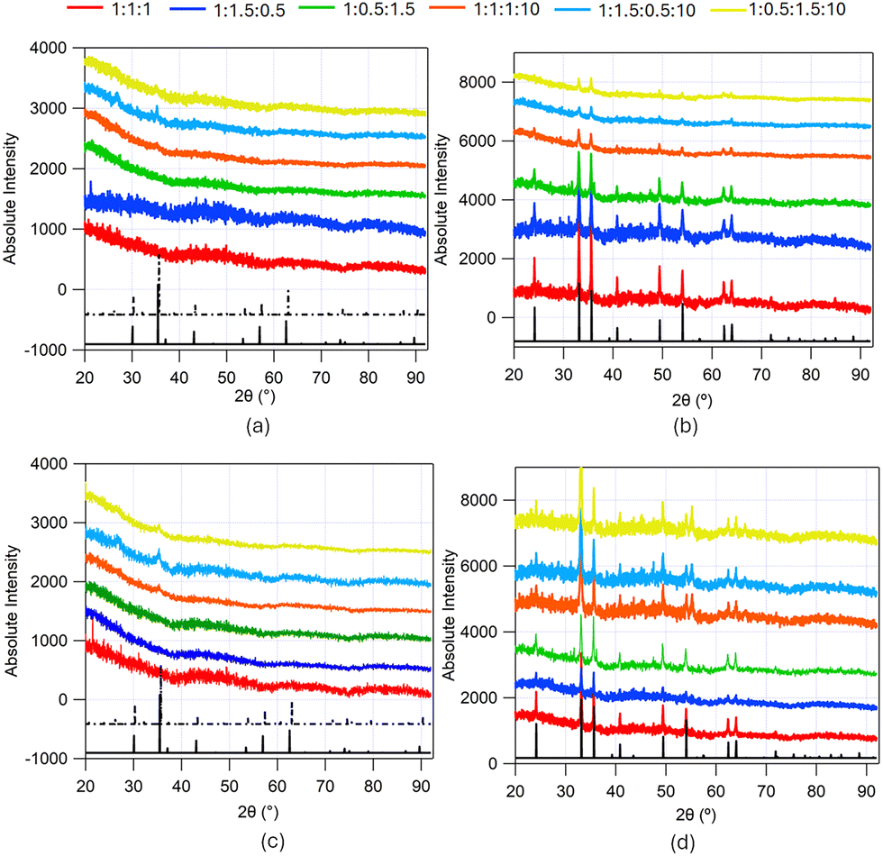 | ||
| Fig. 3 PXRD from iron-containing samples made from the solvothermal synthesis in ChCl:U:Gly DES without and with added CTAB at different solvent compositions (red trace – 1:1:1 DES, blue trace – 1:1.5:0.5 DES, green trace – 1:0.5:1.5 DES, orange trace – 1:1:1:10 DES, cyan trace – 1:1.5:0.5:10 DES and yellow trace – 1:0.5:1.5:10 DES). (a) PXRD from the samples made from DES without CTAB pre-calcination, (b) PXRD from samples made from DES without CTAB post-calcination, (c) PXRD from the samples made from DES with CTAB pre-calcination, (d) PXRD from samples made from DES with CTAB post-calcination. The black traces show the JCPDS XRD patterns of the corresponding compounds: (a) and (c) solid black trace Fe3O4 (magnetite: JCPDS 85-1436) and dashed black trace γ-Fe2O3 (maghemite; JCPDS 25-1402); (b) and (d) solid black trace α-Fe2O3 (haematite; JCPDS 85-0987). | ||
PXRD from uncalcined samples made from unhydrated DES show no peaks, which could be due to the small particle size or amorphous nature of the powder. However, PXRD from uncalcined particles made from hydrated DES show small peaks at 2θ ≈ 28° and 2θ ≈ 35° corresponding to the indistinguishable phases Fe3O4 (magnetite; JCPDS 85-1436; solid black trace in Fig. 3(a) and (c)) or γ-Fe2O3 structure (maghemite; JCPDS 25-1402; dashed black trace in Fig. 3(a) and (c)). The peaks are more prominent in the samples with higher urea content, possibly indicating either a larger number or greater crystallinity of nanoparticles produced. These are consistent with the XRD patterns observed by Hammond et al.18 for iron nanoparticles synthesized from ChCl:urea at a temperature of 150 °C without surfactant. High-resolution TEM images from uncalcined iron-containing nanoparticles synthesized from 1:1:1 and 1:1:1:10 DES, with and without CTAB shown in the ESI,† (Fig. S4) confirm the low crystallinity of the samples, complementing the PXRD data shown in Fig. 3(a) and (c). There are no significant differences between the samples in terms of crystallinity as all the samples appear amorphous or polycrystalline. In order to enhance the crystallinity of the samples and remove any organic materials in the nanoparticles, the particles were calcined at 450 °C for 4 hours.
PXRD from all iron oxide samples post-calcination demonstrate reflections corresponding with the rhombohedral α-Fe2O3 structure (haematite; JCPDS 85-0987; solid black trace in Fig. 3(b) and (d)). These are consistent with the XRD patterns observed by Hammond et al.18 for iron oxide nanoparticles synthesized from ChCl:Urea DES at a temperature of 200 °C. The diffraction peaks in the angular range covered by the experiment (2θ = 20–90°) were: {012}, {104}, {110}, {113}, {024}, {116}, {214}, and {300}. The average crystallite size was determined by applying the Scherrer equation43 by fitting a Lorentzian function to visible peaks and averaging them. These lie in the range 60–80 nm (See Table 1). No systematic effect of crystallite size due to the DES composition of ChCl, urea and glycerol is evident, but on average the samples made from hydrated DES have larger crystallite sizes. This suggests a greater degree of crystallite growth in the hydrated case, likely reflecting the faster diffusion in the less viscous, hydrated mixture. TEM images obtained from the samples confirm the crystallinity of the iron oxide particles and also show crystallite sizes of ∼10s of nm. The high-resolution TEM images from calcined iron oxide nanoparticles synthesized from 1:1:1 and 1:1:1:10 DES, with and without CTAB in ESI,† (Fig. S2) show the d-spacings corresponding to crystal planes of the rhombohedral α-Fe2O3 structure (haematite; JCPDS 85-0987).
| 1:1:1 DES |
1:1.5:0.5 DES |
1:0.5:1.5 DES |
1:1:1:10 DES |
1:1.5:0.5:10 DES |
1:0.5:1.5:10 DES |
|
|---|---|---|---|---|---|---|
| XRD crystallite size (nm) | 62.9 ± 8.4 | 67.2 ± 8.6 | 72.4 ± 9.7 | 60.1 ± 18.4 | 84.0 ± 15.7 | 70.4 ± 15.1 |
| BET surface area (m2 g−1) | 15.1 | 25.2 | 32.3 | 60.1 | 74.2 | 51.7 |
| Micropore Volume (BJH) (cm3 g−1) | 0.14 | 0.29 | 0.21 | 0.75 | 0.54 | 0.35 |
| Pore diameter (BJH) (nm) | 34.4 | 33.7 | 33.7 | 34.8 | 33.2 | 33.3 |
| +CTAB | ||||||
| XRD crystallite size (nm) | 66.9 ± 11.9 | 54.1 ± 18.8 | 44.8 ± 8.2 | 69.1 ± 19 | 64.8 ± 16.8 | 60.8 ± 14.1 |
| BET surface area (m2 g−1) | 20.5 | 7.8 | 16.5 | 31.0 | 22.4 | 19.9 |
| Micropore volume (BJH) (cm3 g−1) | 0.066 | 0.027 | 0.03 | 0.098 | 0.068 | 0.093 |
| Pore diameter (BJH) (nm) | 2.98 | 3.33 | 2.98 | 3.52 | 3.15 | 3.15 |
PXRD from the zinc containing samples made from solvothermal synthesis in ChCl:U:Gly DES with added CTAB at different solvent compositions (1:1:1 DES, 1:1.5:0.5 DES, 1:0.5:1.5 DES, 1:1:1:10 DES, 1:1.5:0.5:10 DES and 1:0.5:1.5:10 DES) before and after calcination, depicting peaks corresponding to the Bragg reflections from the different crystal lattices, are shown in Fig. 4.
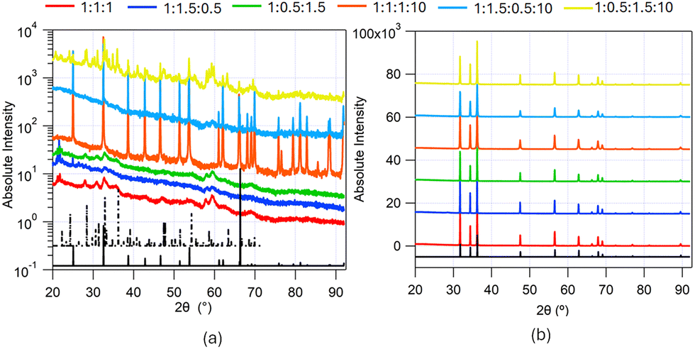 | ||
| Fig. 4 PXRD from zinc-containing samples made from the solvothermal synthesis in ChCl:U:Gly DES with added CTAB at different solvent compositions (red trace – 1:1:1 DES, blue trace – 1:1.5:0.5 DES, green trace – 1:0.5:1.5 DES, orange trace – 1:1:1:10 DES, cyan trace – 1:1.5:0.5:10 DES and yellow trace – 1:0.5:1.5:10 DES). (a) PXRD from the samples pre-calcination, and (b) PXRD from samples post-calcination. The black traces show the JCPDS XRD patterns of the corresponding compounds: (a) solid black trace zinc carbonate (ZnCO3; JCPDS 8-449) and dashed black trace zinc carbonate hydroxide (Zn5 (CO3)2(OH)6; JCPDS 19-1458); (b) solid black trace hexagonal wurtzite structure of ZnO (JCPDS 36-1451). | ||
The uncalcined particles synthesised from the Zn(NO3)2 solutions with CTAB in DES showed clear differences in XRD patterns between different DES. The patterns for the samples precipitated from the hydrated DES with higher urea ratio, i.e. 1:1:1:10 and 1:1.5:0.5:10 DES, were essentially identical and showed clear peaks corresponding to the crystalline phase of zinc carbonate (ZnCO3; JCPDS 8-449; solid black trace in Fig. 4(a)). The PXRD pattern of the hydrated DES with a low urea ratio (1:0.5:1.5:10 DES) showed a diffraction pattern from the zinc carbonate hydroxide (Zn5(CO3)2(OH)6; JCPDS 19-1458; dashed black trace in Fig. 4(a)). This would suggest that, of the hydrated DESs, only the 1:0.5:1.5:10 DES was basic enough to produce the carbonate hydroxide. While initially unexpected, as this solvent contained the lowest proportion of urea, poly-alcohols can enhance urea decomposition to form cyclic carbonates,54 which would result in a greater concentration of ammonia being produced, giving rise to more basic conditions. The higher proportion of glycerol in 1:0.5:1.5:10 DES may lead to this effect, resulting in the formation of the carbonate hydroxide. Each of the unhydrated solutions yielded precipitates which gave poorly resolved XRD patterns, with high noise around the baseline, indicating significantly smaller crystallite sizes and a less crystalline structure. On comparison of the Bragg peaks, these can also be attributed the zinc carbonate hydroxide (Zn5(CO3)2(OH)6; JCPDS 19-1458). The smaller particle size could be due to the higher viscosity of the unhydrated solutions compared to the hydrated solutions. High-resolution TEM images from uncalcined zinc-containing nanoparticles synthesized from 1:1:1 DES with CTAB, shown in the ESI,† (Fig. S5), confirm that the as-synthesized material is polycrystalline, complementing the PXRD data shown in Fig. 4(a), showing a relatively higher degree of crystallinity in comparison to the iron-based samples.
After calcining the zinc-containing samples at 450 °C for 4 hours, each sample was retrieved as a black powder. Calcining these samples at 650 °C for 4 hours yielded a white powder. The black colour seen after calcining at 450 °C was likely due to a thin layer of amorphous carbon, formed by the incomplete burning of CTAB or DES molecules on the particle surface. Calcining at a higher temperature burned away this layer leaving the pure white ZnO. Low calcination temperatures often result in carbon residues on zinc oxide materials. For instance Lu and Yeh reported carbon residues on sub-micron zinc oxide precipitated from water/heptane emulsions55, when calcined at 400 °C, attributed to incomplete burning of the organic species in the system. A white powder resulted from calcination at 700 °C, a temperature high enough to burn off all the organic components. Thermal treatment at either temperature resulted in much larger crystallite sizes, giving sharp diffraction peaks. Nitrogen sorption isotherms also showed no evidence of porosity in the calcined samples, confirming the loss of any nanoscale structuring after heating. The XRD patterns from samples calcined at 450 °C and 650 °C show the same peaks and were identified as the hexagonal wurtzite structure of ZnO (JCPDS 36-1451; solid black trace in Fig. 4(b)). The diffraction peaks in the angular range covered by the experiment (2θ = 20–90°) were: {100}, {002}, {101}, {102}, {110}, {103}, {200}, {112}, {201}, {202} and {203}. High-resolution TEM images from calcined zinc oxide nanoparticles synthesized from 1:1:1 and 1:1:1:10 DES with CTAB, shown in the ESI,† (Fig. S3), show d-spacings corresponding to crystal planes of the hexagonal wurtzite structure of ZnO (JCPDS 36-1451).
3.2. Porosity and structure of the FeOx samples
To characterize the porosity of the iron oxide samples N2 sorption isotherms were measured at 77 K from the samples after calcination at 450 °C and are shown in Fig. 5. BJH analysis was carried out on the data and the pore-size distribution is shown in Fig. S9 (ESI†). The isotherms from samples made without CTAB in the DES exhibit characteristics of non-porous/macroporous material. On the other hand, the isotherms from samples made with CTAB in the DES exhibit characteristics of a mesoporous material but with a lower total surface area. The porosity characterisation parameters (BET specific surface area, pore volume and pore diameter from BJH analysis) are given in Table 1.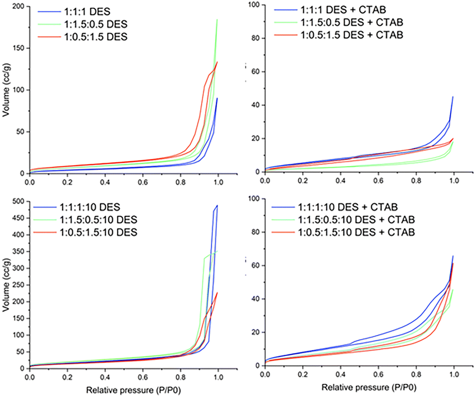 | ||
| Fig. 5 N2 adsorption/desorption isotherms at 77 K for iron oxide samples post-calcination made from the solvothermal synthesis in ChCl:U:Gly DES and ChCl:U:Gly:W DES, with and without added CTAB. | ||
TEM and SEM images were collected from the iron-containing samples made in 1:1:1 DES and 1:1:1:10 DES, without and with CTAB, to characterize the structure and morphology of the iron-containing particles. TEM was collected from samples pre- and post-calcination while SEM was collected from samples post-calcination (Fig. 6). The morphologies for the particles made without and with water are quite distinct, as the latter yields particles with a higher aspect ratio. The presence of water in the DES causes the particles to become more elongated, possibly due to the lower viscosity of the hydrated DES, allowing more reagent to diffuse to the growing particle. The presence of CTAB in the DES, on the other hand results in more compact material. The samples made in the same DES in the presence of CTAB delivered particles with high cohesivity but with gaps indicating the presence of mesopores. The effects on particle morphology are more pronounced in the samples pre-calcination as calcination causes fusing of some of the individual particles to form bigger, more crystalline particles.
 | ||
| Fig. 6 TEM (pre- and post-calcination) and SEM (post-calcination) images from iron oxide samples made from the solvothermal synthesis in 1:1:1 DES and 1:1:1:10 DES, with and without added CTAB. | ||
Iron oxides made from DES without CTAB have a BET surface area between 15 m2 g−1 for the sample with lowest porosity (samples made in 1:1:1 DES) and 74 m2 g−1 for the sample with highest porosity (samples made in 1:1.5:0.5:10 DES), with the surface area being typically larger by 2 to 4× for the samples made from hydrated DES compared to samples made from unhydrated DES. We can see from the TEM images that the particles in samples made from hydrated DES are longer (>100 nm) compared to the ones made from unhydrated DES (∼50 nm), which could lead to less tightly packed aggregates resulting in higher porosity. Increased porosity in nanoparticles synthesised in hydrated DES has been previously reported for cerium oxide nanoparticles33 and work by Hammond et al. on iron oxide nanoparticles synthesized from ChCl:urea DES showed that longer particles were formed when the DES was hydrated.18,53 However, Hammond et al. did not find such large iron oxide particles (>100 nm) in the ChCl:urea DES, suggesting that the presence of glycerol in the DES increases the size of the nanoparticles produced. This could be due to the lower viscosity of the ternary DES (∼0.6 Pa s) compared to ChCl:urea DES (1.6 Pa s),40 which allows reaction components to diffuse together more effectively during synthesis, promoting particle growth. The calculated BJH pore diameter for all the samples is ∼34 nm, which is congruent with poorly packed nanoparticulate samples (crystallite size from XRD ∼50 nm). There is no other structural porosity in these samples, and the TEM images show smooth particle surfaces.
Iron oxide made from DES with CTAB in the DES have BET specific surface area ranging from 7.8 m2 g−1 (samples made from 1:1.5:0.5 DES) to 31 m2 g−1 (samples made from 1:1:1:10 DES) with pore volume ranging from 0.027 cm3 g−1 to 0.098 cm3 g−1 and the pore diameter is ∼3 nm for all samples, with a second peak in the pore size distribution for some samples between 10–20 nm. The overall surface area is smaller than the values obtained for DES without CTAB, but the pore diameter is in the micro/mesoporous range. This appears to be due to compaction of the materials produced in the presence of the surfactant, rather than the more open network seen in the samples made in the DES alone. The TEM images show that the samples made from DES with CTAB have smaller gaps between them, and as there is no change in crystallite size (see XRD data) between samples made from DES with and without CTAB, we conclude that the presence of CTAB allows the crystallites to pack closer together. This may be due to adsorbed layers of surfactant preventing particles sticking together immediately as they aggregate, allowing them to slide over each other into a more energetically favourable, compact arrangement. The smaller pore diameter is also consistent with the micelle diameter and bilayer size of CTAB in the DES.40 This may mean that surfactant coats the particles, promoting compaction of the structures but the presence of surfactant layers or micelles also prevents complete fusion of the nanoparticles during the calcination step.
The specific surface area and the pore volume is higher for the particles made from hydrated DES compared to unhydrated DES. The micelle size for CTAB without any iron/zinc salts in hydrated DES, on the other hand, is slightly smaller than the micelle size in unhydrated DES (data from SANS experiment in ESI;† Fig. S7, Table S4 and Fig. S8). However, insufficient information is available to compare CTAB micelle sizes in hydrated and unhydrated DES upon the addition of salts due to the phase separation of the CTAB + iron-rich phase. The TEM images suggest that the presence of water in the DES changes the morphology of the particles to become more elongated, which prevents close packing even in the presence of surfactant. The specific surface area and the pore volume is highest for the DES with equimolar amounts of urea and glycerol, followed by the DES with lowest urea/glycerol ratio and is lowest for the DES with highest urea.
The BET surface area lies in the broad range reported in literature for iron oxide particles formed from solvothermal synthesis methods56–61 but is lower than that found using some templating mechanisms (∼100 m2 g−1). However, these methods either require extensive hard templating mechanisms with use of sacrificial silica hosts,61 amorphous particles60 or mixed phases.59 In this study high calcination temperatures are used (450 °C) to make crystalline single phase iron oxide, α-Fe2O3, and studies in literature report that increasing calcination temperature results in larger crystals being formed, which are more densely assembled, thereby decreasing the accessible surface area.57,62 The BET surface area is comparable to particles formed via methods which use similar calcination temperatures (∼20 m2 g−1 for polymer templated α-Fe2O3 nanoparticles with calcination temperature of 500 °C62) and to that of materials made using other methods that have similar crystallite size (∼25 m2 g−1 for crystallite sizes of ∼50 nm63). As such, the calcination temperature may be able to further modify crystallite size and surface area depending on the requirement.
4 Conclusions
Here we have demonstrated a solvothermal mechanism whereby iron and zinc oxides can be synthesised from a ternary DES comprising ChCl, urea and glycerol. Previous studies suggested that 80 °C18,54 was the lowest useful temperature at which the thermal degradation of urea in ChCl:urea DES could drive the solvothermal reaction to form iron oxide nanoparticles. However, this and our previous work on cerium nitrate:urea DES33 indicate that solvothermal synthesis of oxide nanoparticles in DES can be achieved at lower temperature, namely 70 °C. This provides controlled decomposition of urea and facilitates generation of nanoscopic particles with various morphologies. Here, in the case of iron, nanoscopic oxide particles were produced directly by this process but for zinc, carbonate species are produced, with broad peaks in the X-ray diffraction also suggesting nanoscopic particles. Calcination caused crystallite growth in both cases, and converted the zinc species into non-porous zinc oxide, while the Fe2O3 materials retained some porosity.The presence of glycerol in the DES means cationic surfactants can be micellised in the DES.40 The effects of such micelles on the inorganic particle growth was therefore investigated in this solvothermal route. Addition of water and surfactant were shown to provide two routes to tune the nanoscopic oxide particle morphology. In the case of iron oxide, it appears that the addition of surfactant in the synthesis promotes aggregation of the inorganic nanoparticles, resulting in lower surface areas, but also retention of mesopores in the structure. Water addition leads to growth of larger more elongated particles, in loose aggregates with higher surface areas. The highest surfaces areas with presence of mesoporosity was therefore obtained when both water and surfactant were present. Further work is needed to optimise the calcination step to remove adsorbed solvent species and surfactant while retaining as much as possible the initially precipitated nanoscale structures.
Data availability
The data supporting this article have been included as part of the ESI.†Conflicts of interest
The authors declare no conflicts of interest.Acknowledgements
I. M. acknowledges funding from EPSRC (Grant Number EP/S020772/1). R. S. A. acknowledges funding from the EPSRC Centre for Doctoral Training in Sustainable Chemical Technologies, EPSRC Grant EP/L016354/1. We thank Dr Gabriele Kociok-Köhn and Dr Remi Castaing at the Material and Chemical Characterisation (MC2) Facility at the University of Bath for their help with the acquisition of the PXRD and the N2 sorption data, respectively. We also thank Crispin Hetherington, research engineer at the National Centre for High-Resolution Microscopy (nCHREM) at Lund University (Sweden) for his support in collecting TEM images. We thank the ISIS Neutron and Muon Source for neutron beamtime (Experiment RB1910484; DOI: 10.5286/ISIS.E.RB1910484) and the ISIS Deuteration Lab for providing the isotopically labelled CTAB surfactant. This work benefited from the use of the SasView application, originally developed under NSF award DMR-0520547. SasView contains code developed with funding from the European Unions Horizon 2020 research and innovation programme under the SINE2020 project, Grant No. 654000.References
- S. Wang, Z. Wang and Z. Zha, Dalton Trans., 2009, 9363–9373 RSC.
- A. Corma and H. Garcia, Chem. Soc. Rev., 2008, 37, 2096–2126 RSC.
- L. Mädler, W. J. Stark and S. E. Pratsinis, J. Appl. Phys., 2002, 92, 6537–6540 CrossRef.
- S. Wang, S. V. Kershaw, G. Li and M. K. H. Leung, J. Mater. Chem. C, 2015, 3, 3280–3285 RSC.
- R. Danish, F. Ahmed and B. H. Koo, Ceram. Int., 2014, 40, 12675–12680 CrossRef CAS.
- A. Nozik, Phys. E, 2002, 14, 115–120 CrossRef CAS.
- M. S. Chavali and M. P. Nikolova, SN Appl. Sci., 2019, 1, 607 CrossRef CAS.
- A. S. Teja and P.-Y. Koh, Prog. Cryst. Growth Charact. Mater., 2009, 55, 22–45 CrossRef CAS.
- H.-Y. Lee, S.-H. Lee, C. Xu, J. Xie, J.-H. Lee, B. Wu, A. L. Koh, X. Wang, R. Sinclair, S. X. Wang, D. G. Nishimura, S. Biswal, S. Sun, S. H. Cho and X. Chen, Nanotechnology, 2008, 19, 165101 CrossRef PubMed.
- S. Odenbach, J. Phys.: Condens. Matter, 2004, 16, R1135 CrossRef CAS.
- S.-W. Cao, Y.-J. Zhu, M.-Y. Ma, L. Li and L. Zhang, J. Phys. Chem. C, 2008, 112, 1851–1856 CrossRef CAS.
- A. Sirelkhatim, S. Mahmud, A. Seeni, N. H. M. Kaus, L. C. Ann, S. K. M. Bakhori, H. Hasan and D. Mohamad, Nano-Micro Lett., 2015, 7, 219–242 CrossRef CAS PubMed.
- A. A. Tayel, W. F. El-Tras, S. Moussa, A. F. El-Baz, H. Mahrous, M. F. Salem and L. Brimer, J. Food Saf., 2011, 31, 211–218 CrossRef CAS.
- M. M. AbdElhady, Int. J. Carbohydr. Chem., 2012, 2012, 840591 Search PubMed.
- P. Singh and A. Nanda, Int. J. Cosmet. Sci., 2014, 36, 273–283 CrossRef CAS PubMed.
- J. Richter and M. Ruck, Molecules, 2020, 25, 78 CrossRef CAS PubMed.
- Y. Nie, Y. Zhou, Y. Zhang, D. Sun, D. Wu, L. Ban, S. Nanda, C. Xu and H. Zhang, Adv. Funct. Mater., 2025, 35, 2418957 CrossRef CAS.
- O. S. Hammond, S. Eslava, A. J. Smith, J. Zhang and K. J. Edler, J. Mater. Chem. A, 2017, 5, 16189–16199 RSC.
- O. S. Hammond, K. J. Edler, D. T. Bowron and L. Torrente-Murciano, Nat. Commun., 2017, 8, 1–7 CrossRef PubMed.
- Q. Xiong, J. Tu, X. Ge, X. Wang and C. Gu, J. Power Sources, 2015, 274, 1–7 CrossRef CAS.
- H.-G. Liao, Y.-X. Jiang, Z.-Y. Zhou, S.-P. Chen and S.-G. Sun, Angew. Chem., Int. Ed., 2008, 47, 9100–9103 CrossRef CAS PubMed.
- J.-Y. Dong, Y.-J. Hsu, D. S.-H. Wong and S.-Y. Lu, J. Phys. Chem. C, 2010, 114, 8867–8872 CrossRef CAS.
- L. Hu, Z. Yan, J. Zhang, X. Peng, X. Mo, A. Wang and L. Chen, J. Mater. Sci., 2019, 54, 11009–11023 CrossRef CAS.
- J. Jiang, C. Yan, X. Zhao, H. Luo, Z. Xue and T. Mu, Green Chem., 2017, 19, 3023–3031 RSC.
- E. R. Cooper, C. D. Andrews, P. S. Wheatley, P. B. Webb, P. Wormald and R. E. Morris, Nature, 2004, 430, 1012–1016 CrossRef CAS PubMed.
- E. R. Parnham, E. A. Drylie, P. S. Wheatley, A. M. Slawin and R. E. Morris, Angew. Chem., 2006, 118, 5084–5088 CrossRef.
- F. Himeur, I. Stein, D. S. Wragg, A. M. Slawin, P. Lightfoot and R. E. Morris, Solid State Sci., 2010, 12, 418–421 CrossRef CAS.
- R. A. Maia, B. Louis and S. A. Baudron, CrystEngComm, 2021, 23, 5016–5032 RSC.
- H. Jia, J. Sun, M. Dong, H. Dong, H. Zhang and X. Xie, Nanoscale, 2021, 13, 19004–19011 RSC.
- S. K. Shahi, S. Sandhu, N. Kaur, J. S. Shahi, M. Kaur, V. Singh and V. Singh, New J. Chem., 2022, 46, 18865–18873 RSC.
- S. Datta, J. Mahin, E. Liberti, I. Manasi, K. J. Edler and L. Torrente-Murciano, ACS Sustainable Chem. Eng., 2023, 11, 10242–10251 CrossRef CAS PubMed.
- H. Jabeen, S. Shaukat and H. M. Abd Ur Rahman, J. Mol. Liq., 2024, 395, 123783 CrossRef CAS.
- I. Manasi, M. R. Andalibi, R. Castaing, L. Torrente-Murciano and K. J. Edler, J. Mater. Chem. A, 2022, 10, 18422–18430 RSC.
- L. Gontrani, D. T. Donia, E. Maria Bauer, P. Tagliatesta and M. Carbone, Inorg. Chim. Acta, 2023, 545, 121268 CrossRef CAS.
- A. P. Abbott, G. Frisch, S. J. Gurman, A. R. Hillman, J. Hartley, F. Holyoak and K. S. Ryder, Chem. Commun., 2011, 47, 10031–10033 RSC.
- S. Datta, C. Jo, M. De Volder and L. Torrente-Murciano, ACS Appl. Mater. Interfaces, 2020, 12, 18803–18812 CrossRef CAS PubMed.
- R. Tabaraki and F. Nazari, J. Fluoresc., 2022, 32, 549–558 CrossRef CAS PubMed.
- Y. Ma, Q. Xia, Y. Liu, W. Chen, S. Liu, Q. Wang, Y. Liu, J. Li and H. Yu, ACS Omega, 2019, 4, 8539–8547 CrossRef CAS.
- I. Manasi, M. R. Andalibi, R. S. Atri, J. Hooton, S. M. King and K. J. Edler, J. Chem. Phys., 2021, 155, 084902 CrossRef CAS.
- R. S. Atri, A. Sanchez-Fernandez, O. S. Hammond, I. Manasi, J. Doutch, J. P. Tellam and K. J. Edler, J. Phys. Chem. B, 2020, 124, 6004–6014 CrossRef CAS PubMed.
- O. S. Hammond, D. T. Bowron and K. J. Edler, Angew. Chem., Int. Ed., 2017, 56, 9782–9785 CrossRef CAS PubMed.
- H. Li, D. Hu, F. Liang, X. Huang and Q. Zhu, R. Soc. Open Sci., 2020, 7, 192092 CrossRef CAS PubMed.
- P. Scherrer, Bestimmung der inneren Struktur und der Größe von Kolloidteilchen mittels Röntgenstrahlen, Springer Berlin Heidelberg, Berlin, Heidelberg, 1912, pp. 387–409 Search PubMed.
- I. Manasi, R. S. Atri, J. Hooton, K. J. Edler and J. Doutch, Micelle Templating in Deep Eutectic Solvents: Ion-micelle interactions (RB1910484), 2019 DOI:10.5286/ISIS.E.RB1910484.
- O. Arnold, J. Bilheux, J. Borreguero, A. Buts, S. Campbell, L. Chapon, M. Doucet, N. Draper, R. Ferraz Leal, M. Gigg, V. Lynch, A. Markvardsen, D. Mikkelson, R. Mikkelson, R. Miller, K. Palmen, P. Parker, G. Passos, T. Perring, P. Peterson, S. Ren, M. Reuter, A. Savici, J. Taylor, R. Taylor, R. Tolchenov, W. Zhou and J. Zikovsky, Nucl. Instrum. Methods Phys. Res., 2014, 764, 156–166 CrossRef CAS.
- S. R. Kline, J. Appl. Crystallogr., 2006, 39, 895–900 CrossRef CAS.
- SasView for Small Angle Scattering Analysis, https://www.sasview.org/.
- M. Su, C. He and K. Shih, Ceram. Int., 2016, 42, 14793–14804 CrossRef CAS.
- V. Bartunek, D. Prucha, M. Švecová, P. Ulbrich, Š. Huber, D. Sedmidubský and O. Jankovský, Mater. Chem. Phys., 2016, 180, 272–278 CrossRef CAS.
- M. Zhu, Q. Luo, Q. Chen, W. Wei, Q. Zhang and S. Li, Mater. Chem. Front., 2021, 5, 2758–2770 RSC.
- R. S. Atri, PhD thesis, University of Bath, 2023.
- T. G. Khonina, E. Y. Nikitina, A. Y. Germov, B. Y. Goloborodsky, K. N. Mikhalev, E. A. Bogdanova, D. S. Tishin, A. M. Demin, V. P. Krasnov, O. N. Chupakhin and V. N. Charushin, RSC Adv., 2022, 12, 4042–4046 RSC.
- O. S. Hammond, R. S. Atri, D. T. Bowron, L. de Campo, S. Diaz-Moreno, L. L. Keenan, J. Doutch, S. Eslava and K. J. Edler, Nanoscale, 2021, 13, 1723–1737 RSC.
- S. P. Simeonov and C. A. M. Afonso, RSC Adv., 2016, 6, 5485–5490 RSC.
- C.-H. Lu and C.-H. Yeh, Mater. Lett., 1997, 33, 129–132 CrossRef CAS.
- W. Jozwiak, E. Kaczmarek, T. Maniecki, W. Ignaczak and W. Maniukiewicz, Appl. Catal., A, 2007, 326, 17–27 CrossRef CAS.
- S. Mpelane, N. Mketo, N. Bingwa and P. N. Nomngongo, Alexandria Eng. J., 2022, 61, 8457–8468 CrossRef.
- J.-H. SmÅtt, N. Schüwer, M. Järn, W. Lindner and M. Lindén, Microporous Mesoporous Mater., 2008, 112, 308–318 CrossRef.
- A. Mitra, C. Vázquez-Vázquez, M. A. López-Quintela, B. K. Paul and A. Bhaumik, Microporous Mesoporous Mater., 2010, 131, 373–377 CrossRef CAS.
- D. Srivastava, N. Perkas, A. Gedanken and I. Felner, J. Phys. Chem. B, 2002, 106, 1878–1883 CrossRef CAS.
- F. Jiao, J.-C. Jumas, M. Womes, A. V. Chadwick, A. Harrison and P. G. Bruce, J. Am. Chem. Soc., 2006, 128, 12905–12909 CrossRef CAS PubMed.
- B. P. Bastakoti, H. Sukegawa, K. C.-W. Wu and Y. Yamauchi, RSC Adv., 2014, 4, 9986–9989 RSC.
- Y. Zhao, F. Pan, H. Li, T. Niu, G. Xu and W. Chen, J. Mater. Chem. A, 2013, 1, 7242–7246 RSC.
Footnote |
| † Electronic supplementary information (ESI) available. See DOI: https://doi.org/10.1039/d5nj00465a |
| This journal is © The Royal Society of Chemistry and the Centre National de la Recherche Scientifique 2025 |