 Open Access Article
Electronic and geometric effects in an Au@NiO core–shell nanocatalyst on the oxidative esterification of aldehydes†
Shaoqi
Zhan
 *a,
Haohong
Song
 b,
Zili
Wu
 cd and
De-en
Jiang
 *e
*e
aDepartment of Chemistry – Ångström Laboratory, Uppsala University, Box 523, 751 20 Uppsala, Sweden. E-mail: shaoqi.zhan@kemi.uu.se
bInterdisciplinary Materials Science, Vanderbilt University, Nashville, Tennessee 37235, USA
cChemical Sciences Division, Oak Ridge National Laboratory, Oak Ridge, Tennessee 37831, USA
dCenter for Nanophase Materials Sciences, Oak Ridge National Laboratory, Oak Ridge, Tennessee 37831, USA
eDepartment of Chemical and Biomolecular Engineering, Vanderbilt University, Nashville, Tennessee 37235, USA. E-mail: de-en.jiang@vanderbilt.edu
First published on 27th November 2024
Abstract
Strong metal–support interactions (SMSIs) are important in heterogeneous catalysis to control stability, activity, and selectivity. Core–shell nanostructures as a unique SMSI system not only stabilize the metal nanoparticles in the core, but also offer tunable structural and electronic properties via their interaction with the support shell. The Au@NiOx core–shell system, for example, is the first commercial nanogold catalyst to produce bulk chemicals via the oxidative esterification of aldehydes. However, how the SMSI effect in Au@NiOx manifests on its oxidative esterification activity is unclear. Here we use a model of an Au13@(NiO)48 core–shell nanocatalyst to examine the Au–NiO interaction and the associated electronic and geometric factors in enabling the oxidation of a hemiacetal (an intermediate from a ready reaction between an aldehyde and an alcohol) to an ester. We found 1.27 (e−) electrons flowing from the NiO shell to the Au core, leading to a higher oxide state of Ni atoms and the stabilization of key intermediates on the NiO shell. More importantly, lower activation energy was found on the Au13@(NiO)48 catalyst than on the Au(111) and NiO(100) surfaces for the rate-limiting step. Microkinetic modeling confirmed the high activity of the Au13@(NiO)48 catalyst in ester production in the experimental temperature range. Our work demonstrates the unique geometric and electronic effects of the Au@NiOx core–shell nanostructure on the catalytic oxidative esterification of aldehydes.
Introduction
Oxide supports can not only increase the thermal stability of metal nanoparticles (NPs) and maintain dispersion, but also influence catalytic properties arising from strong metal–support interactions (SMSIs).1 These interactions alter catalytic properties via charge transfer between the metal and support, creating new catalytically active sites at the interfaces by taking advantage of the synergy between the metal and the support materials.2,3 Tauster et al. reported the first SMSI of Group 8–10 noble metals supported on TiO2 and found that the SMSI reduces the chemisorption capacity of H2 and CO on metals to nearly zero.4 Since then, the SMSI effect has been explored in other metal oxides (for instance, V2O3,5 Nb2O5,6 Ta2O5,7 and CeO2![[thin space (1/6-em)]](https://www.rsc.org/images/entities/char_2009.gif) 8) and metal NPs (such as Au,9 Cu,10 and Ni11). Meanwhile, supported Au nanocatalysts have attracted extensive interest since the pioneering discoveries by Haruta,12 Hutchings,13 and Goodman,14 owing to their effectiveness in catalyzing many important reactions.15–17 However, the commercialization of Au nanocatalysts has been hampered by the fact that Au NPs are liable to sinter during reactions or even under storage.18
8) and metal NPs (such as Au,9 Cu,10 and Ni11). Meanwhile, supported Au nanocatalysts have attracted extensive interest since the pioneering discoveries by Haruta,12 Hutchings,13 and Goodman,14 owing to their effectiveness in catalyzing many important reactions.15–17 However, the commercialization of Au nanocatalysts has been hampered by the fact that Au NPs are liable to sinter during reactions or even under storage.18
As a special SMSI system, the core–shell design of a metal NP inside an oxide shell not only stabilizes metal core NPs, but also introduces tunable structural and electronic properties arising from the core–shell interaction.19 For instance, Dai and coworkers tuned the Au144@Fe2O3 core–shell catalyst to increase the catalytic activity for CO oxidation.20 Zhang et al. manipulated the TiOx overlayer on Ru nanocatalysts to regulate their catalytic reactivity for the Fischer–Tropsch synthesis,21 while Polo-Garzon et al. found alcohol-induced formation of TiOx on Au NPs that can be controlled to fully or partially cover surface Au sites to modulate CO oxidation activity.22
The first commercial Au nanocatalyst for the production of bulk chemicals was based on a core–shell design: Suzuki et al. invented the Au@NiOx core–shell catalyst that was found to have high activity, selectivity, and long lifetime for the aerobic oxidative esterification of aldehydes, compared with conventional supported Au NP catalysts.23 Esterification is one of the most fundamental transformations in organic synthesis and the product ester is widely used in industries and cosmetics. Aerobic oxidative esterification of aldehydes with alcohols is an attractive method for the synthesis of esters because of its environmentally benign and neutral conditions. To understand the high activity of the Au@NiOx core–shell catalyst for oxidative esterification of aldehydes, Hayashi et al. employed a NiO/Au slab model to represent the Au@NiOx core–shell NP and simulated the reaction pathways of direct oxidative esterification using density functional theory (DFT).24,25 Their findings attributed the high activity to the strong basic site on the NiO surface due to Ni vacancies in the subsurface. However, it remains unclear whether these findings based on the slab model can be directly translated to the real catalyst, which comprises 2–3 nm Au NPs with a thin NiOx shell.
Given the rich sites on a NP surface such as corners and edges, the study of oxidative esterification using a true Au@NiOx core–shell model instead of the NiO/Au slab model could offer new and more insights into the geometric effect of the core–shell structure on the reaction. Herein, we employ a core–shell model of the Au@NiOx NP catalyst in our DFT computation to examine the geometric structure and electronic interaction between the metal core and the oxide shell and their impacts on oxidative esterification. For comparison, we also examine the Au(111) and NiO(100) surfaces. Microkinetic modeling (MKM) will be further used, based on DFT energetics, to simulate the catalytic activity. Below, we first explain in detail the DFT method, our catalyst models, and the MKM approach.
Computational details
All the DFT calculations were performed with the Vienna ab initio simulation package (VASP).26,27 The electron–core interactions were described by the projected augmented wave (PAW) method28 and electron exchange–correlation was expressed at the generalized gradient-approximation (GGA) level using the Perdew–Burke–Ernzerhof (PBE) functional.29 A cutoff energy of 500 eV was adopted for the plane-wave basis set. All calculations were performed with spin polarization. For structural optimization, a convergence threshold of 0.02 eV Å−1 was set in force and the total energy was converged to within 10−5 eV. van der Waals interaction was included via Grimme's method (DFT-D3).30 DFT+U was used for the chemistry on NiO (100),31 with U − J = 6.3 eV.32The Au13@(NiO)48 core–shell NP was constructed from the icosahedral Au55 NP33 by replacing its outer layer with NiO. This was followed by placing the core–shell NP inside a 25 × 25 × 25 Å3 cubic box and fixing the center Au atom. Only the Γ-point was used for sampling the Brillouin zone for the core–shell model. For the NiO(100) and Au(111) slabs, a five-layered 4 × 4 supercell of 40 Ni and 40 O atoms and a four-layered 4 × 4 supercell of 64 Au atoms were constructed, respectively. A vacuum layer of 15 Å was added in the z direction and the Brillouin zone was sampled using a 3 × 3 × 1 k-point mesh for the two slab models.
Simulated annealing via ab initio molecular dynamics (AIMD) was performed at 500 K for 500 steps (1 fs per step), followed by cooling to 300 K to relax the core–shell model before the DFT geometry optimization. The quasi-Newton algorithm34–36 was used to obtain stable and transition-state structures. To locate the transition state (TS), the climbing-image nudged elastic band (NEB)37,38 method was used with a convergence criterion of 0.05 eV A−1. The adsorption energy of key species on the surface was calculated according to Eads = Esur–mol − Esur − Emol, where Esur–mol, Esur, and Emol represent the energies of the adsorbed configuration, the surface, and the isolated adsorbate, respectively. Bader charge analysis was used to obtain the partial atomic charges.39 VESTA was used to draw the structures.40
The MKMCXX code was used for microkinetic modeling.41 A simple plug flow reactor mode was assumed under the reaction conditions of 300–700 K and 1.0 bar for a mixture of 40% aldehydes, 40% methanol, and 20% O2 balance in mole fractions. More details can be found in the ESI.†
Results and discussion
Pathways of the oxidative esterification of acetaldehyde with methanol
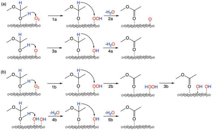
The overall reaction of oxidative esterification involves two molecules of aldehyde reacting with two molecules of alcohol and one molecule of O2 to produce two molecules of ester and two molecules of water. The commercial process converts methacrolein and methanol to methyl methacrylate (MMA), a monomer used in the production of acrylic plastics. Here for simplicity, we use acetaldehyde as a reactant (Scheme 1). The first step, hemiacetalization between acetaldehyde and methanol, readily occurs,25 so we focus on the subsequent oxidative dehydrogenation of the hemiacetal to the ester, which is the key reaction to be catalyzed. We propose two pathways for this process (Scheme 2): (a) the oxo pathway (_oxo) and (b) the hydrogen peroxide pathway (_H2O2). The two pathways share the same first step: the 1st dehydrogenation of the hemiacetal (steps 1a and 1b in Scheme 2) by O2 to form *OOH. The _oxo pathway (Scheme 2a) continues with 2nd dehydrogenation, O–OH2 cleavage, and H2O formation/desorption, leading to the 1st ester product and an *O (step 2a); this is followed by the 2nd hemiacetal adsorption and dehydrogenation by the *O, leading to the formation of the 2nd ester product and the 2nd water molecule (steps 3a and 4a). In the _H2O2 pathway (Scheme 2b), the 2nd dehydrogenation of the first hemiacetal leads to the formation of the 1st ester product and *HOOH on the surface (step 2b), which then dissociates into two *OH groups (step 3b). The second hemiacetal then reacts with the two *OH groups via two sequential dehydrogenation steps, forming the 2nd ester product and two water molecules (steps 4b and 5b). Of note, only the _H2O2 pathway was explored previously for the NiO/Au slab model.25 Before proceeding to explore both the _oxo and _H2O2 pathways, we examine the geometric and electronic properties of the Au13@(NiO)48 model catalyst. | ||
| Scheme 1 The overall reaction of the oxidative esterification of acetaldehyde with methanol via a hemiacetal intermediate. | ||
Structure and charge transfer in the Au13@(NiO)48 core–shell catalyst and adsorption of reactants and products
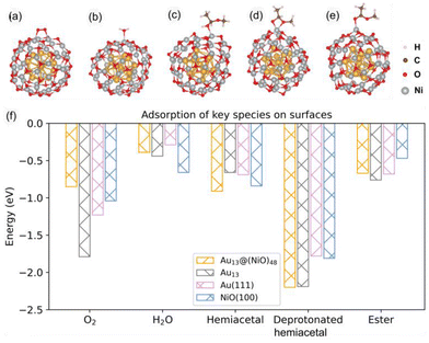
In the optimized Au13@(NiO)48 core–shell model (Fig. 1a), 48 Ni atoms and 48 O atoms are bonded mainly via a hexagonal structure to form a shell surrounding a centered-icosahedral Au13 core with an Au–O distance of ∼3.1 Å and an Au–Ni distance of ∼2.7 Å. In the (NiO)48 shell, the average coordination numbers of Ni and O atoms are around 3. The diameter of the core–shell model is ∼1.1 nm, about half the measured sizes of the Au@NiO particles (2–3 nm).23 The interaction energy between the Au13 core and the (NiO)48 shell was estimated to be −0.7 eV per NiO, computed from the difference in energy between the core–shell structure and the frozen, isolated Au13 core and the (NiO)48 shell. This highly favorable energetics suggests a strong electronic/chemical interaction between the Au13 core and the (NiO)48 shell. The calculated Bader charges show that 1.27 electrons (e−) transfer from the (NiO)48 shell to the Au13 core. The charge density difference plot clearly shows electron accumulation in the Au13 core and depletion of the shell (Fig. 1b). Although the charge transfer direction is usually from a metal to an oxide, the Au metal is special in that it has the highest electronegativity among all metals. Au also has high work functions of 5.30–5.45 eV for thin films,42 while the NiO films tend to have lower work functions of 4.4–4.8 eV.43,44 Because electrons will transfer from a lower work function material to a higher one when the two materials establish electronic contact and their vacuum levels align, our computed charge transfer direction from the NiO shell to the Au core is fully consistent with the experimentally measured work functions. The slightly oxidized NiO shell will greatly influence the adsorption of reactants and the subsequent surface reactions, which are explored as follows.Although the optimized Au13@(NiO)48 structure is not perfectly symmetric (Fig. 1a), the local coordination environments of Ni and O show some uniformity in the (NiO)48 shell: most of the Ni sites have three O atoms in the first coordination shell. So we just chose the most representative Ni site for our study to reduce the computational cost of exploring all different sites and pathways. Fig. 2a–e show the adsorption geometries of five key species of oxidative esterification (namely, O2, H2O, hemiacetal, deprotonated hemiacetal, and ester) on Au13@(NiO)48, while the adsorption energies are shown in Fig. 2f. Adsorption energies on Au13, Au (111), and NiO (100) are included for comparison (see Fig. S1 and Table S1† for details). One can see that the adsorption of the O2 molecule becomes weaker, while the adsorption of the hemiacetal becomes stronger on the Au13@(NiO)48 core–shell structure than on Au13, Au (111), and NiO (100). The adsorption energies of H2O and ester molecules on the Au13@(NiO)48 core–shell structure are in the middle of the values among the four different systems. Comparing the four neutral adsorbates (O2, H2O, hemiacetal, and ester) on the four different surfaces (Fig. 2f), one notices an interesting balanced-out effect: the four molecules adsorb moderately strongly with a similar strength on the Au13@(NiO)48 core–shell structure. This aligns well with Sabatier's principle for the “just right” adsorption strength. The adsorption of deprotonated hemiacetal, which will be examined in detail below, is strong on all four surfaces and slightly stronger on the core-shell structure and the Au13 cluster.
Oxidative dehydrogenation of a hemiacetal on Au13@(NiO)48
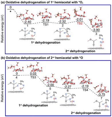
As mentioned earlier, the reaction between an aldehyde and an alcohol to form a hemiacetal is facile, and we found that this is indeed the case between acetaldehyde and methanol on Au13@(NiO)48, Au(111), and NiO(100) (Fig. S2†). We note that unlike the conventional homogeneous process where an acidic proton is needed to catalyze the reaction, the mechanism of the hemiacetal reaction is different on the Au13@(NiO)48 catalyst where the nucleophilic attack and the proton transfer take place simultaneously via a four-membered-ring transition state with a very low activation energy of 0.24 eV (Fig. S2a†). This facileness of the hemiacetal reaction has also been found by Hayashi et al. in their slab model of the NiO/Au catalyst.25 Therefore, we focus on the subsequent steps of oxidative dehydrogenation of the hemiacetal to produce ester and water molecules. Both the hemiacetal and O2 adsorb on a Ni site of Au13@(NiO)48 in a monodentate mode (state 1 in Fig. 3a). We found that the 1st dehydrogenation step is facilitated by hydrogen transfer from the adsorbed hemiacetal to *O2via a methanol reactant (the corresponding transition state is denoted as TS1 in Fig. 3a; Ea = 0.21 eV). The deprotonated hemiacetal adsorbs on the Ni site in a bidentate mode (state 2 in Fig. 3a), where the two Ni–O bonds are 1.86 and 2.01 Å. The 2nd dehydrogenation step is a bifurcation point into two different pathways: (a) the _oxo pathway and (b) the _H2O2 pathway.Oxidative dehydrogenation of hemiacetals on Au(111) and NiO(100)
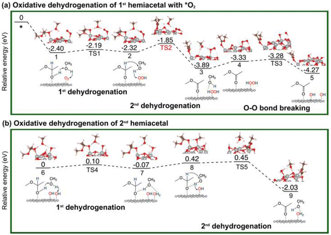
For comparison, we have also explored the reaction pathways on Au(111) (Fig. 5 and Fig. S3†) and NiO(100) (Fig. 6 and Fig. S4†) in the oxidative dehydrogenation of hemiacetals. On Au(111), the 1st dehydrogenation step has an activation energy of 0.23 eV (the corresponding transition state is denoted as TS1 in Fig. 5a). In the subsequent _oxo pathway, the 2nd dehydrogenation step has an activation energy of 0.68 eV (the corresponding transition state is denoted as TS2). After desorbing the first ester product, dehydrogenations of the second hemiacetal proceed with activation energies of 0.13 eV and 0.36 eV (Fig. S3a†). In the _H2O2 pathway, the 2nd dehydrogenation of the 1st hemiacetal has a relatively high activation barrier of 0.81 eV (the corresponding transition state is denoted as TS2 in Fig. 5b). The O–O bond breaking of HOOH is slightly unfavorable with an energy barrier of 0.37 eV (TS3). The subsequent oxidative dehydrogenation of the 2nd hemiacetal (Fig. S3b†) has activation energies of 0.02 and 0.31 eV for the 1st and 2nd dehydrogenation steps, respectively. The formation of the second water molecule is also very energetically favorable with a reaction energy of −2.24 eV.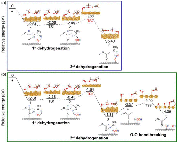 | ||
| Fig. 5 Energy profiles of the oxidative dehydrogenation of the 1st hemiacetal on Au (111): (a) via the _oxo pathway; (b) via the _H2O2 pathway. | ||
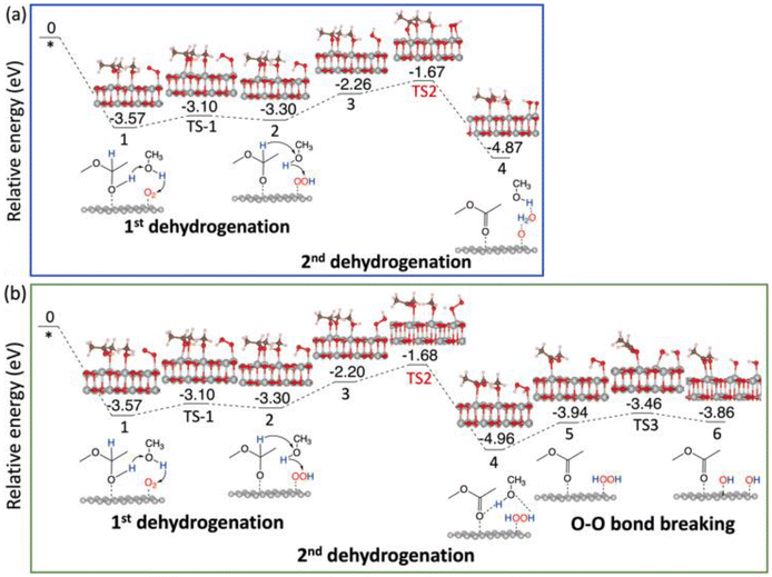 | ||
| Fig. 6 Energy profiles of the oxidative dehydrogenation of the 1st hemiacetal on NiO(100): (a) via the _oxo pathway; (b) via the _H2O2 pathway. | ||
On NiO(100), the 1st dehydrogenation step of the oxidative dehydrogenation of the hemiacetal has an activation energy of 0.47 eV (the corresponding transition state is denoted as TS1 in Fig. 6a). In the subsequent step, both pathways experience an unfavorable configuration for the 2nd dehydrogenation. In the _oxo pathway, there is an uphill energy of 1.04 eV for the configuration change, followed by an activation energy of 0.57 eV (the corresponding transition state is denoted as TS2) for the 2nd dehydrogenation step. After desorbing the first ester product, the 1st dehydrogenation of the second hemiacetal proceeds spontaneously with no activation energy, and the 2nd dehydrogenation of the second hemiacetal occurs with an activation energy of 0.24 eV (Fig. S4a†). In the _H2O2 pathway, the uphill energy climbs for 1.10 eV, followed by an activation barrier of 0.52 eV (the corresponding transition state is denoted as TS2 in Fig. 6b) in the 2nd dehydrogenation. The O–O bond breaking of HOOH is unfavorable with an energy barrier of 0.48 eV (TS3). Similar to the _oxo pathway, the 1st dehydrogenation of the second hemiacetal proceeds spontaneously, and the subsequent oxidative dehydrogenation of the 2nd hemiacetal (Fig. S4b†) has an activation energy of 0.24 eV. Hence the _H2O2 pathway is slightly more favorable compared to the _oxo pathway.
Comparing Au13@(NiO)48, Au(111), and NiO(100) for the oxidative dehydrogenation of hemiacetals, we found that the rate-limiting steps (the second dehydrogenation of the first hemiacetal) have activation energies of 0.3–0.5 eV on Au13@(NiO)48, but 0.7–0.8 eV on Au(111), and 0.5–0.6 eV on NiO(100). To understand this difference, we next analyze the difference in adsorption of key intermediates.
Comparison of key intermediates on Au13@(NiO)48, Au(111), and NiO(100)
Because the rate-limiting step is the dehydrogenation of the deprotonated hemiacetal, here we focus on the adsorption of the deprotonated hemiacetal in the three systems. We found that the bidentate model can be better stabilized on Au13@(NiO)48 (Fig. 7a) than monodentate adsorption on Au13@(NiO)48 (Fig. 7b) and the bridging mode on Au(111) and NiO(100) surfaces (Fig. 7c and d), as also reflected in adsorption energies (Fig. 2f; Table S2†). The bidentate mode was also observed in the transition state structures on Au13@(NiO)48 (Fig. S5†). The particular bidentate mode on Au13@(NiO)48 arises from the low coordination of Ni2+, the more favorable steric environment of the spherical core–shell structure than a flat structure (Fig. S6†), and the slightly higher oxide state than Ni2+, which stabilize the deprotonated hemiacetal. In contrast, we found that the dehydrogenation of the hemiacetal in the monodentate mode on Au13@(NiO)48 would have a higher activation energy (Fig. S7†).Microkinetic modeling of the oxidative dehydrogenation of hemiacetal pathways on Au13@(NiO)48, Au(111), and NiO(100)
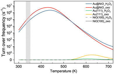
Based on the DFT energy profiles, we carried out microkinetic modeling of the oxidative dehydrogenation of hemiacetal pathways on Au13@(NiO)48 in comparison with Au(111) and NiO(100). We simulated the ester production rates as a function of temperature for both the _oxo and _H2O2 pathways. From Fig. 8, one can see that from 300 K up to 500 K, the Au13@(NiO)48 nanocatalyst is highly active for the oxidative dehydrogenation of a hemiacetal to an ester, in agreement with the experiment which was run at 358 K.23 Only after 600 K does Au(111) begin to show activity. In addition, there is a switchover of the preferred pathway from _oxo to _H2O2 for the Au13@(NiO)48 system at 510 K. At the experimental temperatures (358 K), our simulations indicate that the reaction proceeds mainly via the _oxo pathway. Although both the previous slab model and the present core–shell model confirmed the experimental hypothesis of the oxidized NiO being the key to oxidative esterification catalysis,23 the present work offers a new perspective of the electronic effect due to the charge transfer between the Au core and the NiO shell as well as a geometric factor of enhanced adsorption of hemiacetals.Comparison of the Au13@(NiO)48 model with the NiO/Au slab model
It is informative to compare the present mechanistic study using the Au13@(NiO)48 core–shell model with the previous work by Hayashi et al. employing a NiO/Au slab model.24,25 Both studies found that the oxidized form of NiO is crucial in enabling the oxidative dehydrogenation of hemiacetals, but the difference is how the oxidized NiO appears; in the present work, the oxidation of NiO stems from the charge transfer from the NiO shell to the Au shell while maintaining the 1![[thin space (1/6-em)]](https://www.rsc.org/images/entities/char_2009.gif) :
:![[thin space (1/6-em)]](https://www.rsc.org/images/entities/char_2009.gif) 1 stoichiometry of Ni
1 stoichiometry of Ni![[thin space (1/6-em)]](https://www.rsc.org/images/entities/char_2009.gif) :
:![[thin space (1/6-em)]](https://www.rsc.org/images/entities/char_2009.gif) O, whereas in the slab model of Hayashi et al., the Ni atom was manually removed to create a Ni vacancy and a NiOx (x > 1) layer. We think that in the real Au@NiO catalyst, both scenarios could be present, even though our work here shows that oxidation of the NiO shell could evolve naturally from the NiO/Au interface.
O, whereas in the slab model of Hayashi et al., the Ni atom was manually removed to create a Ni vacancy and a NiOx (x > 1) layer. We think that in the real Au@NiO catalyst, both scenarios could be present, even though our work here shows that oxidation of the NiO shell could evolve naturally from the NiO/Au interface.
The other difference is that in our Au13@(NiO)48 core–shell model, we found that the _oxo pathway is preferred over the _H2O2 pathway for the moderate temperatures at which the reaction was conducted experimentally, while Hayashi et al. examined only the _H2O2 pathway in their slab model. Moreover, the strong bidentate adsorption state of the deprotonated hemiacetal was found to be an important intermediate in our Au13@(NiO)48 core–shell model, which was not found in the slab model. In addition, the activation energies for the key steps in our Au13@(NiO)48 core–shell model are generally lower than those in the slab model with Ni vacancies. However, we note that the aldehyde reactant is different between the two studies: we used acetaldehyde as a model reactant, while Hayashi et al. used a real reactant, namely methacrolein, as in the commercial process. In summary, we think that the two models are complementary and provide a more complete picture of the Au@NiO catalyst.
Conclusions
We have simulated the superior performance of the Au@NiO nanocatalyst in the oxidative esterification of aldehydes using a more realistic Au13@(NiO)48 core–shell model. We found that 1.27 (e−) electrons transfer from the (NiO)48 shell to the Au13 core, leading to a slightly oxidized NiO shell. This core–shell construction has an important consequence in balancing the adsorption energies of reactants and key intermediates: weakening O2 adsorption and strengthening hemiacetal adsorption. Facile formation of a hemiacetal between acetaldehyde and methanol was found on the Au13@(NiO)48 surface. DFT energetics and MKM modeling of subsequent dehydrogenation of the hemiacetal by molecular oxygen confirmed the superior activity of Au13@(NiO)48 over Au(111) and NiO(100) in producing the ester and water at moderate temperatures (300 K–450 K). The low coordination, spherical structure, and high oxide state of Ni atoms in Au13@(NiO)48 stabilized the key intermediates via a bidentate adsorption mode, a geometry not observed in slab models. Our work has demonstrated the unique electronic and geometric effects of the Au@NiO core–shell nanostructure in enabling the oxidative esterification of aldehydes.Data availability
The data supporting this article have been included as part of the ESI.†Conflicts of interest
The authors declare that they have no known competing financial interests or personal relationships that could have appeared to influence the work reported in this paper.Acknowledgements
This work was sponsored by the U.S. Department of Energy, Office of Science, Office of Basic Energy Sciences, Chemical Sciences, Geosciences, and Biosciences Division, Catalysis Science Program. This research used resources of the National Energy Research Scientific Computing Center, a DOE Office of Science User Facility supported by the Office of Science of the U.S. Department of Energy under contract no. DE-AC02-05CH11231. SZ thanks the National Academic Infrastructure for Supercomputing in Sweden (NAISS) (allocation no. NAISS 2024/5-22 and NAISS 2024/6-130) in Linköping, Sweden.References
- T. Pu, W. Zhang and M. Zhu, Angew. Chem., Int. Ed., 2023, 62, e202212278 CrossRef CAS PubMed.
- C. Gao, F. Lyu and Y. Yin, Chem. Rev., 2021, 121, 834–881 CrossRef CAS PubMed.
- T. W. Deelen, C. H. Mejía and K. P. de Jong, Nat. Catal., 2019, 2, 955–970 CrossRef.
- S. J. Tauster, S. C. Fung and R. L. Garten, J. Am. Chem. Soc., 1978, 100, 170–175 CrossRef CAS.
- S.-I. Ito, C. Chibana, K. Nagashima, S. Kameoka, K. Tomishige and K. Kunimori, Appl. Catal., A, 2002, 236, 113–120 CrossRef CAS.
- K. Kunimori, K. Ito, K. Iwai and T. Uchijima, Chem. Lett., 1986, 15, 573–576 CrossRef.
- S. J. Tauster and S. C. Fung, J. Catal., 1978, 55, 29–35 CrossRef CAS.
- M. Mao, H. Lv, Y. Li, Y. Yang, M. Zeng, N. Li and X. Zhao, ACS Catal., 2016, 6, 418–427 CrossRef CAS.
- H. Tang, J. Wei, B. Qiao, X. Pan, L. Li, J. Liu, J. Wang and T. Zhang, J. Am. Chem. Soc., 2016, 138, 56–59 CrossRef CAS PubMed.
- R. Belgamwar, R. Verma, T. Das, S. Chakraborty, P. Sarawade and V. Polshettiwar, J. Am. Chem. Soc., 2023, 145, 8634–8646 CrossRef CAS PubMed.
- R. Ye, L. Ma, X. Hong, T. R. Reina, W. Luo, L. Kang, G. Feng, R. Zhang, M. Fan, R. Zhang and J. Liu, Angew. Chem., Int. Ed., 2023, e202317669 Search PubMed.
- M. Haruta, T. Kobayashi, H. Sano and N. Yamada, Chem. Lett., 1987, 16, 405–408 CrossRef.
- G. J. Hutchings, J. Catal., 1985, 96, 292–295 CrossRef CAS.
- M. Valden, X. Lai and D. W. Goodman, Science, 1998, 281, 1647–1650 CrossRef CAS PubMed.
- M. Sankar, Q. He, R. V. Engel, M. A. Sainna, A. J. Logsdail, A. Roldan, D. J. Willock, N. Agarwal, C. J. Kiely and G. J. Hutchings, Chem. Rev., 2020, 120, 3890–3938 CrossRef CAS PubMed.
- T. Ishida, T. Murayama, A. Taketoshi and M. Haruta, Chem. Rev., 2020, 120, 464–525 CrossRef CAS PubMed.
- Y. Zhang, J. Zhang, B. Zhang, R. Si, B. Han, F. Hong, Y. Niu, L. Sun, L. Li, B. Qiao, K. Sun, J. Huang and M. Haruta, Nat. Commun., 2020, 11, 558 CrossRef CAS PubMed.
- R. Zanella and C. Louis, Catal. Today, 2005, 107–108, 768–777 CrossRef CAS.
- P. Wu, S. Tan, J. Moon, Z. Yan, V. Fung, N. Li, S. Z. Yang, Y. Cheng, C. W. Abney, Z. Wu, A. Savara, A. M. Momen, D. Jiang, D. Su, H. Li, S. Zhu, H. Zhu and S. Dai, Nat. Commun., 2020, 11, 3042 CrossRef CAS PubMed.
- M. Lukosi, C. Tian, X. Li, S. M. Mahurin, H. M. Meyer, G. S. Foo and S. Dai, Catal. Lett., 2018, 148, 2315–2324 CrossRef CAS.
- Y. Zhang, X. Yang, X. Yang, H. Duan, H. Qi, Y. Su, B. Liang, H. Tao, B. Liu, D. Chen, X. Su, Y. Huang and T. Zhang, Nat. Commun., 2020, 11, 3185 CrossRef CAS PubMed.
- F. Polo-Garzon, T. F. Blum, V. Fung, Z. Bao, H. Chen, Z. Huang, S. M. Mahurin, S. Dai, M. Chi and Z. Wu, ACS Catal., 2020, 10, 8515–8523 CrossRef CAS.
- K. Suzuki, T. Yamaguchi, K. Matsushita, C. Iitsuka, J. Miura, T. Akaogi and H. Ishida, ACS Catal., 2013, 3, 1845–1849 CrossRef CAS.
- A. Hayashi, Y. Ato, K. Tada, H. Koga, T. Kawakami, S. Yamanaka and M. Okumura, e-J. Surf. Sci. Nanotechnol., 2018, 16, 242–246 CrossRef CAS.
- A. Hayashi, Y. Ato, K. Tada, H. Koga, T. Kawakami, S. Yamanaka and M. Okumura, J. Phys. Chem. C, 2020, 124, 17039–17047 CrossRef CAS.
- G. Kresse and J. Furthmüller, Comput. Mater. Sci., 1996, 6, 15–50 CrossRef CAS.
- G. Kresse and J. Furthmüller, Phys. Rev. B: Condens. Matter Mater. Phys., 1996, 54, 11169–11186 CrossRef CAS PubMed.
- P. E. Blöchl, Phys. Rev. B: Condens. Matter Mater. Phys., 1994, 50, 17953–17979 CrossRef PubMed.
- J. P. Perdew, K. Burke and M. Ernzerhof, Phys. Rev. Lett., 1996, 77, 3865 CrossRef CAS PubMed.
- S. Grimme, J. Antony, S. Ehrlich and H. Krieg, J. Chem. Phys., 2010, 132, 154104 CrossRef PubMed.
- S. Dudarev, G. Botton, S. Savrasov, C. Humphreys and A. Sutton, Phys. Rev. B: Condens. Matter Mater. Phys., 1998, 57, 1505–1509 CrossRef CAS.
- A. M. Ferrari and C. Pisani, J. Chem. Phys., 2007, 127, 174711 CrossRef PubMed.
- F. Hidalgo, C. Noguez and M. Olvera de la Cruz, Nanoscale, 2014, 6, 3325–3334 RSC.
- W. H. Press, B. P. Flannery, S. A. Teukolsky and W. T. Vetterling, Numerical Recipes, 2nd ed, Cambridge University Press, New York, 1986 Search PubMed.
- J. Nocedal, Math. Comput., 1980, 35, 773–782 CrossRef.
- D. Shanno, Math. Comput., 1970, 24, 647 CrossRef.
- G. Henkelman and H. Jonsson, J. Chem. Phys., 2000, 113, 9978–9985 CrossRef CAS.
- D. Sheppard and G. Henkelman, J. Comput. Chem., 2011, 32, 1769–1771 CrossRef CAS.
- W. Tang, E. Sanville and G. Henkelman, J. Phys.: Condens. Matter, 2009, 21, 084204 CrossRef CAS PubMed.
- K. Momma and F. Izumi, J. Appl. Crystallogr., 2011, 44, 1272–1276 CrossRef CAS.
- I. A. W. Filot, B. Zijlstra and E. J. M. Hensen, MKMCXX, a C++ program for constructing microkinetic models, 2018, https://www.mkmcxx.nl Search PubMed.
- W. M. H. Sachtler, G. J. H. Dorgelo and A. A. Holscher, Surf. Sci., 1966, 5, 221–229 CrossRef CAS.
- E. L. Ratcliff, J. Meyer, K. X. Steirer, A. Garcia, J. J. Berry, D. S. Ginley, D. C. Olson, A. Kahn and N. R. Armstrong, Chem. Mater., 2011, 23, 4988–5000 CrossRef CAS.
- S. Hietzschold, S. Hillebrandt, F. Ullrich, J. Bombsch, V. Rohnacher, S. Ma, W. Liu, A. Köhn, W. Jaegermann, A. Pucci, W. Kowalsky, E. Mankel, S. Beck and R. Lovrincic, ACS Appl. Mater. Interfaces, 2017, 9, 39821–39829 CrossRef CAS PubMed.
Footnote |
| † Electronic supplementary information (ESI) available. See DOI: https://doi.org/10.1039/d4nr03302g |
| This journal is © The Royal Society of Chemistry 2025 |

