
 Open Access Article
 This Open Access Article is licensed under a
 Creative Commons Attribution 3.0 Unported Licence
Intense, self-induced sustainable microwave plasma using carbon nanotubes made from CO2†
Gad Lichta,
Kyle Hofstetterb and
Stuart Licht *abc
*abc
aDirect Air Capture LLC, A4 188 Triple Diamond Blvd, North Venice, FL 34275, USA
bCarbon Corp, 1035 26 St NE, Calgary, AB T2A 6K8, Canada
cDept. of Chemistry, George Washington University, Washington, DC 20052, USA. E-mail: slicht@gwu.edu
First published on 30th January 2025
Abstract
An intense, microwave-driven plasma is triggered and sustained with carbon nanotubes made directly from CO2. Purification is one of many prospective energy applications. Self-purification of molten carbonate split CO2 synthesized CNTs is 100× quicker, consumes 10× less power, and produces higher purity than with conventional plasma treatment.
Introduction
In 2019 an unusual plasma was analysed that forms when a conventional microwave irradiates grapes or hydrogel beads.1 Here, we show an intense, continuous, microwave-driven plasma induced without water, but rather triggered by Graphene NanoCarbons (GNCs) such as Carbon NanoTubes (CNTs). The intensity and continuous nature of the plasma is limited to GNC CNTs formed directly from CO2 by molten carbonate electrolysis. A range of applications can be explored with this new plasma. In this initial study, the application is limited to the study of these plasmas as an effective environment to increase CNT purity. This communication is limited in scope to the readiness of formation, continuity, and intensity of this CNT-induced plasma. Future studies will focus on the detailed characterization of the intense CNT-induced plasma, while this study notes the ease that which this energy source acts to self-purify CNTs.Graphite surfaces, microwave absorption, and microplasma
Graphite surfaces and powders have been modified with various applied plasmas with surface effects being more pronounced under argon plasmas.2 Microwaves have been used to selectively heat natural graphites and can induce localized heating and purification in graphites.3,4 “Micro-plasmas” or sparks (discontinuous, short-lasting bright emissions) have been observed over microwave-irradiated graphite.5Microwave and plasma synthesis and treatment of GNCs
Microwaves or pyrolysis have been used to synthesize,6,7 treat, or modify GNCs8–15 and CNTs.16–24 Microwave-driven plasmas have been generated in gases including He, Ar, O2, CO2, and air.25–29 Microwave-driven gas and arc plasmas have been used to synthesize, treat, or modify CNTs30–41 and other nanostructures.42,43 GNCs55–66 have also been synthesized or treated with gas plasmas generated by other means than microwaves, such as inductively coupled,44–48 arc,49,50 torch,51 thermal and O2,52,53 N2,54 air,55,56 and other gas plasmas.57–68 None of these studies use any form of GNCs to generate (trigger and sustain) microwave-driven plasmas (as observed in this study).2–68GNC properties conducive to plasma induction
CNT and GNC physical/chemical characteristics could facilitate a prospective microwave-driven plasma formation. CNTs and Carbon Nano-Onions (CNOs) exhibit high microwave absorptivity.18,40,69 CNTs have high strength, electrical conductivity, electron mobility, stability, and a strong capacity to dissipate heat.71–85 CNTs enhance electron field emissions; such properties may also be conducive to potential microwave-driven plasmas. Emitting electrons and focusing electrons at high voltages can cause gas and other particles to ionize at lower temperatures than expected by purely thermal means. CNTs have been shown to emit electrons at high voltages, currents, and efficiency compared to thermal emitters of electrons such as thermionic devices.86–92CNTs from the greenhouse gas CO2
In 2009 and 2010, the energy-efficient splitting of CO2 into carbon (C) and oxygen (O2) through molten carbonate electrolysis emerged as a promising approach to tackle climate change.93,94 The utilization of high-solubility molten paths and innovative renewable energy-driven electrolysis techniques has significantly reduced both energy consumption and costs. Subsequently, in 2015, it was demonstrated that during this electrolysis, the growth of transition metal nuclei leads to the direct conversion of CO2 into pure CNTs95–99 and other GNCs:| CO32−(molten) ± 4e− → C(GNC) + O2(gas) + O2−(dissolved) | (1) |
CO2 undergoes a chemical reaction with the electrolytic oxide, as described by eqn (1), to regenerate CO32− following eqn (2):
| CO2(gas) + O2−(dissolved) → CO32−(molten) | (2) |
Combining eqn (1) and (2) yields a net decarbonization reaction:
| CO2(gas) ± 4e− → C(GNC) + O2(gas) | (3) |
During electrolysis, CO2 is split into O2 and GNCs. These GNCs form a matrix of interconnected structures with the electrolyte on the cathode, as depicted in (1). Synthesized GNCs also encompass helical, thin-walled, magnetic, and doped CNTs, along with carbon nano-bamboo, nano-pearl, nano-tree morphologies, and graphene.100–109 Additional specifics regarding the electrolysis process, including product separation from excess electrolyte and product washing, have recently been documented.110 This mixture of GNCs and carbonate electrolyte at the cathode is termed a carbanogel. The carbanogel is purified by separating the GNCs from the electrolyte.110,111 CO2 electrolysis parameters are manipulated to tailor the type of GNC produced by controlling the temperature, current density, and electrolyte composition. For instance, a lower temperature (725 °C) is typically used for the electrolytic production of CNOs,102 while a higher temperature range (750 to 770 °C) is employed for synthesizing CNTs through electrolysis.95–105
CNT self-induced, continuous microwave plasma
The direct conversion of CO2 to CNTs is an opportunity to remove this greenhouse gas in the production of stable GNC allotropes, thereby contributing to climate change mitigation. Long-term CO2 removal is a critical component of effective carbon capture. Graphite, a macroscopic form of layered graphene, serves as a mineral with a geological lifespan spanning hundreds of millions of years, offering a stability benchmark for synthesized GNC materials.This study presents an intense CNT self-induced, continuous microwave plasma; the plasma is confined, but produced in an open container. The sole reactant preparing these CNTs is the greenhouse gas CO2. Such continuous plasmas are not found to be induced by other CNTs prepared by conventional methodologies. The plasma is effective in purifying the CNTs.
Experimental section
Carbanogel formation from CO2
Lithium carbonate was purchased at a battery grade >99.5% and was used as received. As purchased the Li2CO3 was battery grade 99.5%, but was received with an analysis of 99.8% (Li2CO3, Shanghai Seasongreen Chemical Co.). HCl, (31.45% Cleartech) H2O2 (35%, Aquabond), HNO3 (70% ACS reagent, Sigma) and HClO4 (70% ACS reagent, Sigma) were used in GNC purification. Muntz brass is a high-zinc brass alloy composed of 60% copper and 40% zinc; this material is also referred to as brass 280. This material serves as the cathode and was purchased from onlinemetals.com and in larger quantities from Marmetal Industries. Electrolysis was conducted in 304 Stainless Steel (SS304) “carbon pots”. The pot acts as both the cell case and its inner walls serve as the anode.CO2 was split in accord with eqn (1)–(3) in 770 °C molten Li2CO3 between a Muntz brass cathode and a SS304 anode. The CO2 source of the CNTs in this study is the (5% CO2) flue gas from the Shepard Energy Centre natural gas power plant in Calgary, CA. GNC on the cathode grows as a carbanogel matrix with interstitial electrolyte as in SEM in Fig. 1 panel E. A benefit of isolating nanoparticles within a macroscopically sized matrix as individual agglutinated, particles is that these macroscopic carbanogel particles mitigate respiratory hazards. Specifically, potential hazards sometimes associated with shipping nanoscopic particles are avoided. Other benefits are the structure provides an electrical and thermal conductive matrix, along with a highly porous framework for the accommodation of composite material, and catalysts, or battery intercalation. The SEM of the GNC carbanogel in Fig. 1 panel E is of a CNT product after an initial HCl wash. At higher SEM magnification, the same electrolysis product shows that the individual carbanogel particles are composed of high-purity CNTs. Other electrolysis conditions such as lowering of the electrolysis temperature led to the formation of CNO products in Fig. 1 panel G.
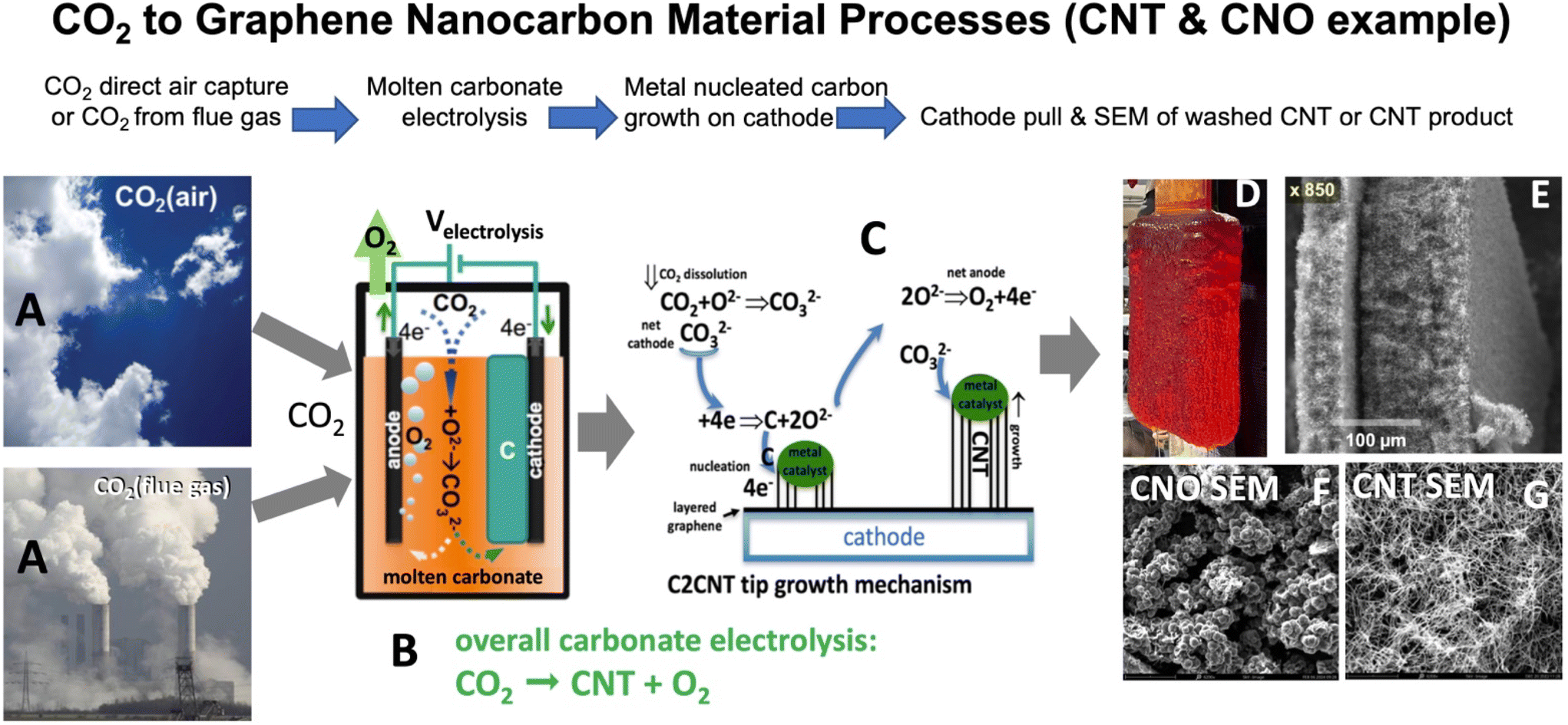 | ||
| Fig. 1 The CO2 to graphene nanocarbon material process (carbon nanotube example). (A) CO2 is removed directly from air or flue gas (without preconcentration). (B) CO2 is electrolyzed in molten carbonate. (C) The transition metal nucleated mechanism of electrolytic CO2 transformation to CNT at the electrolysis cathode. (D) A pulled 1700 cm2 cathode with deposited carbanogel (CNTs retaining interstitial electrolyte) subsequent to 18 hour electrolysis at 0.6 A cm−2 in 770 °C Li2CO3. SEMs of (E) carbanogel subsequent to excess electrolyte removal (100 μm bar). (F & G) CNO & CNT electrolysis products from CO2 (10 μm bar). | ||
Raman, TGA and microscopy of the carbanogel product
Thermogravimetric analysis (TGA) of the product was analysed with a PerkinElmer STA 6000 TGA/DSC. Scanning electron microscopy was performed using a PHENOM Pro-X Scanning Electron Microscope. SEM, TEM, X-ray, and Raman analyses of both CNT and various GNC products have been documented in the ESI.† TGA is conducted under air, from 30–800° at 5 °C min−1. SEM CNT or CNT purity is determined by a minimum of 12 SEM inspections of the sample. The CNTs range from 5 to 25 μm in length. Raman spectra were collected with a LabRAM HR800 Raman microscope (HORIBA). This Raman spectrometer/microscope used an incident laser light with a resolution of 0.6 cm−1 at 532.14 nm wavelength.Fig. 2 presents Raman of the CNTs. The Raman spectrum exhibits two sharp peaks at 1350 and 1580 cm−1. These correspond to the disorder-induced mode (D band) and the high-frequency E2G first order mode (G band) respectively, and an additional peak is evident, the 2D band, at 2700 cm−1. The intensity ratio between the D band and the G band (ID/IG) of 0.2 is characteristic of low disorder MWCNTs.
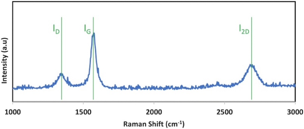 | ||
| Fig. 2 Raman spectrum of the carbon nanotube product synthesized by the electrolytic splitting of CO2 between a Muntz brass cathode and a stainless steel 304 anode in 770 °C Li2CO3. | ||
CNT-induced microwave plasma generation
A borosilicate vessel alone in a microwave does not produce a plasma. However, in the same borosilicate vessel containing CNTs from CO2, in a microwave, there is a plasma. Subsequent to CO2 electrolysis, a desired weight of the washed, ground carbanogel was placed in borosilicate (Pyrex) Erlenmeyer flasks, beakers, or ceramic crucible (alumina). The sample was then placed at the centre of the microwave for 1 min, the sample was filmed while the microwave was applied, and the heating, electrical, and plasma quality of the product was observed. Two different microwave instruments were employed. One was a conventional (Model 201) 650 W output power laboratory microwave with a turntable and a 16L chamber volume. The turntable homogenizes the applied microwave field avoiding extended exposure to low or high field variations. The second was a commercial-scale Panasonic NE-3280 microwave, with 3200 W output power, a ceramic floor, and no visible turntable.The NE-3280 provides a larger 44L microwave chamber, a 5-fold higher microwave power, and turntables, both below the ceramic floor and in the microwave ceiling, to maintain applied microwave field homogeneity. Alternatively, for comparison, the CNTs were treated with a conventional RF-driven plasma using a TCH-55, generating 300 W of RF plasma. The TCH-5S is driven by a 40 kHz RF frequency and has a 150 mm × 270 mm inner chamber with a 5L capacity. All plasmas were generated in ambient air.
CNT self-purification by the induced microwave plasma
Plasmas were applied to various CNT samples and were characterized by TGA and SEM. Self-induced microwave or RF plasmas were applied to the samples for a fixed duration, and post-treatment were again characterized by TGA and SEM.Results and discussion
Observation of intense, self-induced sustainable microwave plasma using CNTs from CO2
Fig. 3 presents a brilliant plasma that arises in three repeat runs of a 1 g CNT sample in an Erlenmeyer flask irradiated at 2.45 GHz in an NE-3280 microwave at 3020 W irradiation. The videos of the three intense plasmas are Movie 1 (https://youtu.be/GRzeSMIZI_c), Movie 2 (https://youtu.be/1zqAYVEmFX0), and Movie 3 (https://youtu.be/MbUHwm0ikLY) (each is also available in the ESI†).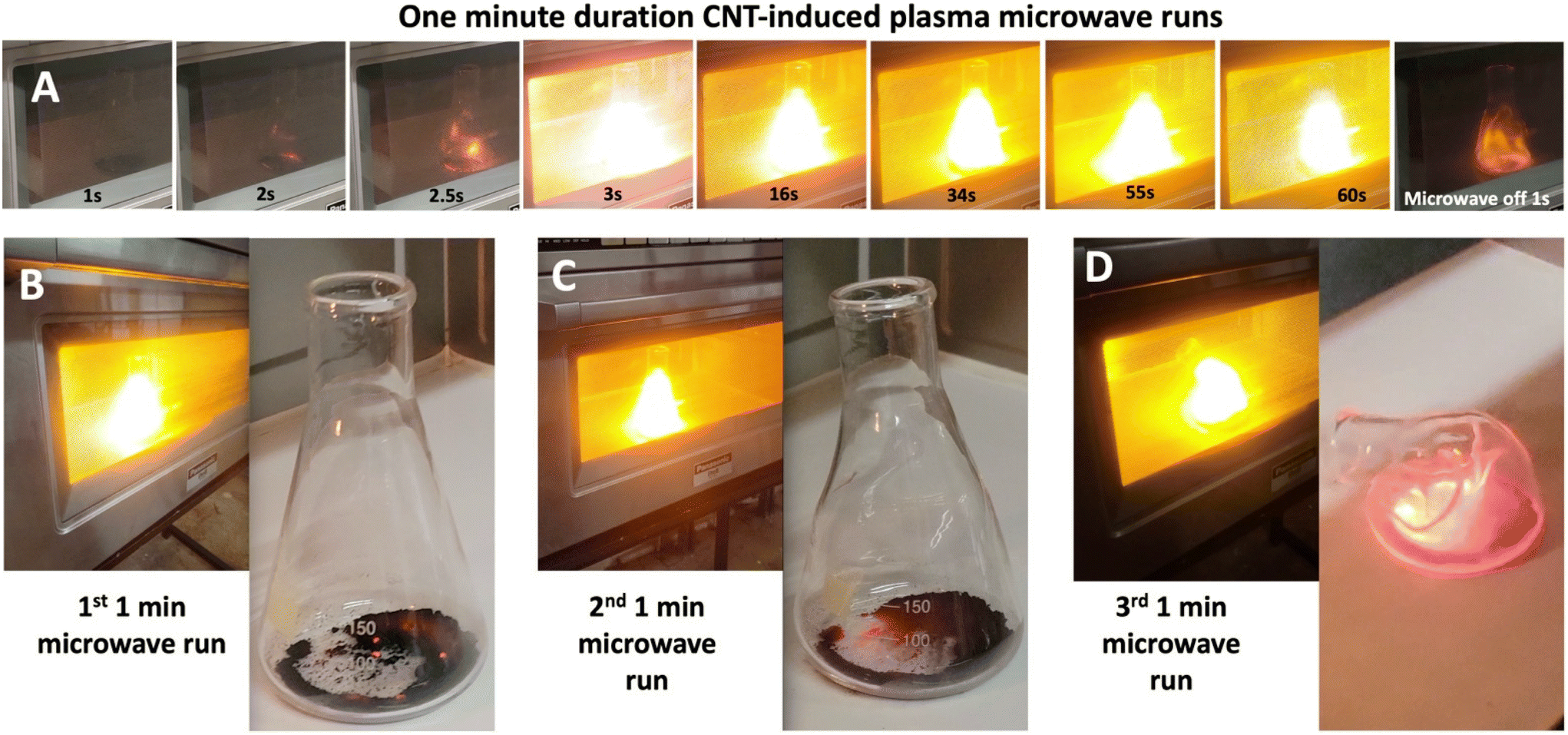 | ||
| Fig. 3 (A) A 1 min microwave run, at various time intervals of a 1 g sample in an Erlenmeyer flask of a 95% purity C2CNT CNT generated in 770 °C Li2CO3 using a Muntz brass cathode and 304 stainless steel cathode at a 0.45 A cm−2 electrolysis current. Note, that the CNT is heated by the microwave and triggers the plasma at 3 s, and that is then continuous throughout the 1 min microwave time. As seen in the top right panel, the plasma spontaneously extinguishes at the end of the applied microwave power. Each run is at 3200 W in the NE3280 microwave. (B–D) Three consecutive 1 min microwave runs of the sample are also shown in the top row. The plasma began to soften the borosilicate flask by the end of the second run, and the softened flask had collapsed due to the plasma heat by the end of the third run. | ||
CNTs used in Fig. 3 were grown from 5% CO2 flue gas. The flue gas was electrolyzed in 770 °C molten Li2CO3 for 17 hours at 2800 A on a 6232 cm2 cathode (electrolysis current density J = 0.45 A cm−2). This is a cathode comparable in shape and composition, but larger, than the post-electrolysis cathode shown in Fig. 1, panel D. The cathode is across from a SS304 electrode serving as both the anode and as the cell case. Post electrolysis, the electrolysis product was collected from the cathode, excess electrolyte removed, HCl washed, and (pre-) analysed with 95% SEM purity.
In each microwave irradiation, as exemplified in the top row of Fig. 3, the CNT in the flask triggers a continuous, sustained bright yellow–white plasma throughout the 1 minute of applied microwave irradiation. In the first few seconds, the sample turns partially red with microwave heating, followed in the next second by induction and triggering of the continuous plasma. The plasma is accompanied by an audible 120 Hz hum presumably related to a variation of the applied microwave source.
The bottom of Fig. 3 shows the sample with the microwave-driven plasma, and then with the flask removed from the microwave at the end of each of the three runs. In each, as seen in the movies the plasma was sustained at a uniform, undulating intensity throughout. The sample in the flask remains intact after the first and second runs. Note, that the sample remains partially red hot (cooling ∼3 s) after the irradiation was terminated, and that the sample remains substantially intact after the first and second runs. The plasma began to soften the borosilicate flask by the end of the second run, and the softened flask had collapsed due to the plasma heat by the end of the third run. This establishes a lower limit to the plasma temperature as the 820 °C softening temperature of this borosilicate 7740 Pyrex glass.
A variety of GNCs samples were also irradiated for 1 min, but at a five-fold lower power of 650 W in a Model 201 Laboratory Microwave, rather than in the NE-3280. As seen in Movie 4 (https://www.youtube.com/watch?v=rosw5xtymHg, also available in the ESI†), a consistently intense plasma is again observed, emanating from the sample within an open Pyrex beaker. 1 g of the CNT used in Fig. 3 triggers, and again sustains, this bright plasma. The CNTs were observed to require a longer plasma trigger time of ∼10 s, rather than ∼2 s occurring with the higher power microwave.
Under the same microwave conditions, plasmas were ignited, but quickly extinguished (not sustained) using either (i) 1 g of in-house synthesized 90% SEM purity 99% TGA purity carbon nano-onions (CNOs), see Movie 5 (https://youtu.be/VXYRFQeLs9A, also available in the ESI†), or 1 g of commercial (ii) similar sized, synthesized CVD M8 98% (Timesnano) MWCNTs, see Movie 6, (https://youtu.be/Pg0BEALfnuE, also available in the ESI†), or (iii) thinner CVD 87% NC7000 MWCNTs (Nanocyl). As seen in Movie 5† (for the CNOs) intermittent sporadic plasmas and flames were observed during the one minute of 650 W microwave irradiation. The Nanocyl CNTs (not shown) exhibited no observable consistent plasma and occasional sparking.
The same sustained plasma is reproducibly observed in three additional CNT samples grown in-house from CO2. Each were synthesized in separate 16 hour electrolyses of CO2 in 770 °C Li2CO3, each at a current density of J = 0.6 A cm−2, and using Muntz brass cathodes and 304 stainless steel anodes. Each was prepared with CO2 from the flue gas of the Shepard natural gas power plant in Calgary, Canada. The first was analysed with 95% SEM and TGA CNT purity; the second with 90% SEM and 97% TGA purity, and the third with 95% SEM and 97% TGA purity as further detailed in the ESI.† As with the first sample, each of the 3 out of 3 of the CNT samples chosen from an inventory of in-house CNTs, under 1 min of 650 W microwave power, reliably triggered the bright, continuous plasma.
A fascinating phenomenon was observed in Movie 7 (https://youtu.be/wsdw5TaIMfg, also available in the ESI†), in a second run, following the run in Movie 4† (https://youtu.be/rosw5xtymHg), of the microwave irradiation of an in-house CNT from CO2 sample in a beaker. In this case, the triggering of the plasma split the beaker, and the plasma escaped intact, and migrated intact to the top of the microwave where it continued as a bright, continuous oval-shaped plasma throughout the full minute of irradiation, only extinguishing with the end of the microwave irradiation. Stainless steel 304 is resistant to oxidation to 925 °C, and the lack of oxidation as the microwave SS304 ceiling establishes this maximum temperature of the plasma. Hence the plasma, which can soften borosilicate is within the temperature range of 820–925 °C. An expanded study will probe the optical spectrum at a variety of spatial regions within the plasma. For now, we note that the intense yellow/white in the videos of the plasma and the images of Fig. 3 and 4 correlate with a borosilicate plasma in air based on the 840 °C borosilicate softening as the lower limit of the plasma temperature. A source of molten borosilicate is the plasma softened borosilicate glass as exemplified by the melted flask on the right side of Fig. 3.
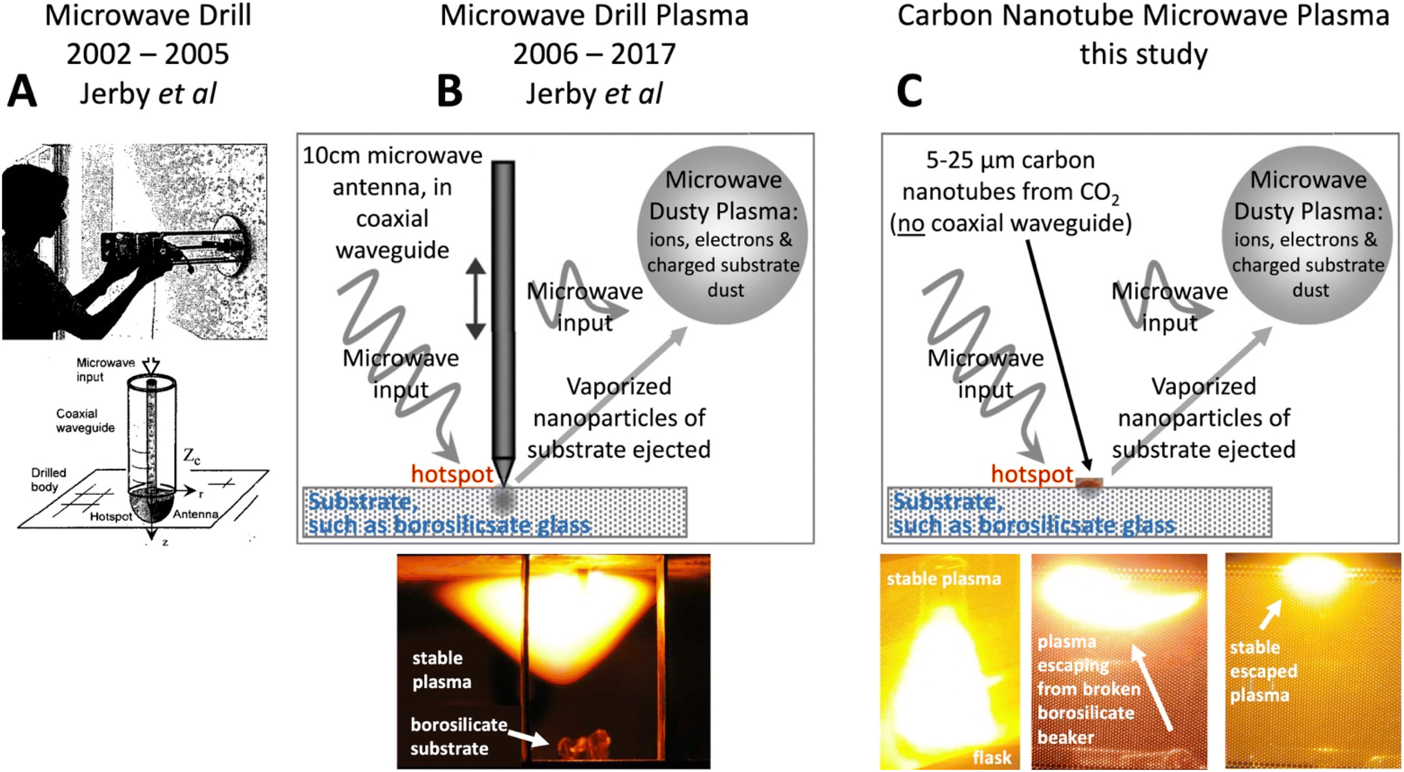 | ||
| Fig. 4 Model of the new CNT Microwave Plasma modelled as evolved from the Microwave Drill Plasma. (A) 2002–2005: The Microwave Drill (as modified from Jerby et al., Science, 2002 and subsequent studies). This requires a ∼10 cm antenna to focus the microwave, creating a hotspot to drill through a substrate. (B) 2006–2017: The Microwave Drill Plasma, the antenna induced substrate hotspot ejects substrate nanoparticles to initiate a sustained microwave plasma. (C) This study: Without a macroscopic antenna, the new Carbon Nanotube Microwave creates a hotspot on the substrate, which initiates the observed sustained microwave plasma. | ||
Model of the CNT microwave plasma origin
Older studies have shown that large, dense plasma spheres are not perfect reflectors, even though they can, to some extent, be modelled as perfect conductors. For example, this has been demonstrated for larger (∼700× the wavelength), hotter (free electron-dominated), spherical, irradiated plasmas. Furthermore, for smaller sizes discrepancies from plasmas behaving as perfect reflectors were expected to increase.112 In the current study, the plasma size is roughly the same size as the 12.2 cm wavelength of the applied 2.45 GHz microwave irradiation.Interestingly, the observed plasmas, here induced with CNTs, partially resemble those made with a macroscopic device. This device is a coaxial waveguide, also referred to as a “microwave drill bit” consisting of a cylinder with an inner conductive antenna, which can be lowered to make contact with a material. This coaxial waveguide contains a moving central macroscopic electrode antenna, that acts to direct input microwave radiation to induce molten hotspots at the point of contact in germanium, alumina, NaCl, silicon, copper, basalt, or other materials.113–122 This releases airborne particles of those materials ranging from 10 nm to several microns in size. These particles act as partially ionized emitters in a sustained “dusty plasma”. A feature of these observed dusty, also referred to as complex, plasmas is the tendency to spontaneously adapt its shape to absorb most of the transmitted microwave energy. The optical emission spectrum of the fireballs is in accord with the originating material (Cu hot spots exhibit the copper lines, NaCl the sodium line, Si the silicon atomic spectrum, and Cs powder on glass both the Si and Cs characteristic emission spectrum).113,114
As shown in the panel A of Fig. 4, Jerby et al. developed the Microwave Drill bit from 2002 to 2005.113–115 It uses ∼10 cm electrodes made of copper, tungsten, carbon, or silicon carbide as microwave antenna absorbers to concentrate heat at the electrode–substrate contact point, reaching temperatures over 1000 K. The thermal energy emitted by the microwave monopole antenna and the power absorbed by the substrate are described by Maxwell's equations for a lossy medium, as detailed in ref. 115 and summarized in ref. 114.
As shown in panel B of Fig. 4, the microwave drill creates a hotspot on the substrate, which vaporizes nanoparticles. These ejected nanoparticles ignite and form a stable plasma due to the electrostatic interaction of the charged particles. With continued microwave irradiation, a sustained, undulating dusty plasma forms, consisting of ions, electrons, and charged substrate dust.120
Jerby et al. observed Microwave Drill Plasmas forming on substrates in air, including borosilicate (bright white/orange–yellow) and cesium (pink). The distinct spectral lines of generated plasmas were measured for various substrates (Si), lime-glass (Na & K), copper (Cu), and sodium chloride (Na, Cl). Other substrates observed to form Microwave Drill Plasmas in air include basalt, alumina, germanium (Ge), iron (Fe), and titanium (Ti). The plasmas contained nano- or small micro-particles originating from the substrate.117–122
In 2006, Jerby et al. noted that the Microwave Drill Plasma adapts to the microwave source. They modelled the plasma as a lumped load in parallel with a microwave transmission line (as described in ref. 115). An adaptive impedance-matching mechanism tends to maximize the microwave power absorbed by the plasma “by a self-tuning optimization of its intensity, position and power”.120 Fig. 5A shows their measured microwave reflection coefficients at three stages: (i) before microwave ignition, (ii) during the ignition of substrate nanoparticles, and (iii) during the resulting plasma state.119 Fig. 5B–D show the measured microwave reflections during these stages in Smith-Chart format.122 Fig. 5E shows the calculated microwave reflection on a Smith-Chart, highlighting the plasma's tendency to “self-impedance match”, as described in ref. 119. More recently, it was noted that after the microwave ignition of the substrate, the plasma can be sustained by a direct current (DC) supply, even after the microwave is turned off.123
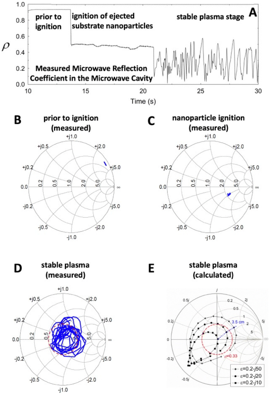 | ||
| Fig. 5 The microwave reflection coefficient during various stages of formation of a Microwave Drill Plasma. (A) Microwave Reflection coefficient versus time. (B)–(E) Smith Charts. Modified from ref. 115. | ||
As shown in panel C of Fig. 4, we introduce here a model for a new carbon nanotube (CNT)-triggered plasma, in concurrence with our observed microwave plasma, without a microwave drill bit or external coaxial waveguide. The characteristics of the CNT and Drill Microwave-induced plasmas, as seen in panels 4B and 4C, are similar. Both emit intense white–orange–yellow light from a borosilicate substrate, undulate within a confined region, and continue even after being disconnected from the substrate. However, the new CNT Microwave generates a hotspot on the borosilicate substrate that initiates a sustained microwave plasma, without the need for a macroscopic antenna.
After the CNT-induced hotspot forms, the plasma evolves in a manner similar to the macroscopic microwave drill antenna: ejected substrate nanoparticles are vaporized, ignited, and, under continuous microwave irradiation, the bipolar charged particles electrostatically aggregate to form a spatially constrained, impedance-matched plasma. Following ignition, as with the Microwave Drill Plasma,123 the new CNT-induced microwave plasma can likely be sustained by DC power after the microwave is turned off, a topic for future study.
The question arises: why do MWCNTs made from CO2channel microwave energy, create hotspots to directly induce microwave plasma formation? This is observed to occur without the need for a macroscopic moveable antenna placed within a coaxial waveguide. A portion of the expanded response lies in both the physical–chemical properties of MWCNT compared to single walled CNTs (SWCNTs), and to the specific physical–chemical differences between CVD and C2CNT CO2 synthesized carbon nanotubes. In brief, (i) CNTs are excellent microwave absorbers due to their high permittivity (both dielectric constant and loss factor).124 However, C2CNTs have two additional properties that enhance microwave absorption and facilitate the high temperatures needed to form substrate hotspots for microwave plasmas: (ii) increased conductivity and (iii) high ferromagnetic character.124–126
Fundamental advantages of MWCNT in contrast to SWCNT to trigger and sustain microwave-driven-plasmas
Multi-walled carbon nanotubes (MWCNTs) produce a narrower emission band than single-walled carbon nanotubes (SWCNTs), which may enhance constructive interference and improve plasma yield, though this hypothesis requires further investigation.18,53,75,89 Additionally, MWCNTs likely broaden the microwave absorption spectrum compared to SWCNTs, as nanotubes of different diameters absorb varying wavelengths. This effect is primarily due to the narrower emission band and the redistribution of energy through the skin effect across the expanded surface area of MWCNTs.MWCNTs are more rigid than SWCNTs, which helps maintain their morphology under harsh plasma conditions. Additionally, the lifetime of MWCNTs can improve if outer layers are corroded during plasma exposure while inner layers remain intact.5 MWCNTs also tend to exhibit metallic conductivity, whereas SWCNTs are metallic only in certain, larger diameter configurations.
Interactions between MWCNT layers enhance electron and hole mobility, improving microwave absorption.85–100 The higher metallic nature of MWCNTs allows for easier electron migration between CNT bundles or within individual tubes.54,92 Plasma-induced electron or hole loss has less impact on MWCNTs, as they can handle higher currents.86–98 Their rigidity, greater carbon content, and ability to sustain higher currents may enable better reductive healing in plasma compared to SWCNTs. MWCNTs are also less likely to break at defects and their higher density and mass make them less prone to displacement by plasmas.99–101 Additionally, MWCNTs have a higher heat capacity and more thermal vibration modes, helping them radiate and dissipate surface energy more effectively.102–104
Plasma-advantaged properties of CNTs from CO2
CNTs synthesized via molten carbonate electrolytic CO2 splitting (C2CNT) offer distinct advantages for plasma generation compared to those made by conventional CVD or arc ablation. C2CNTs are magnetic and have higher metal or metal carbide content,104 which enhances electron mobility and intrinsic electronic conductivity. Both their higher metal content and higher C2CNT intrinsic electronic conductivity have been reported.98,104 Longer CNTs99 generally provide better conductivity, structural robustness, and support more vibrational modes. The thicker, multi-walled C2CNTs can carry higher currents, exhibit better skin effect and microwave absorptivity, and are more chemically and physically robust. They also promote positive electron emission, hole conduction, and improved thermal conductivity. Additionally, C2CNTs’ unique micro-to-macro structures, formed from carbanogel, enhance microwave absorption, ion trapping, and heat retention. Metallic impurities in C2CNTs can further increase electron and hole availability, improve conductivity by bridging gaps, catalyse molecule (substrate) splitting, aid CNT regeneration, and enhance magnetic interactions with EM fields, boosting absorptivity. Their high thermal conductivity also facilitates efficient microwave heat transfer to both plasma substrates and ejected nanoparticles.Discussion on the mechanism of microwave power coupling with CNTs
The previous two sections detail that microwave absorption by CNTs is highly system dependent. Although CNTs are much smaller than the 12.2 cm wavelength of the applied microwave irradiation, effective coupling of the microwave power to the CNTs can still be achieved. This is possible when the CNTs have well-matched permittivity and permeability, which significantly reduces the effective wavelength of the microwave irradiation within the CNT.Many of the systems previously studied to understand microwave power coupling to CNTs focus on higher frequencies than the 2 to 4 GHz S-band microwave radiation used in this study.127–136 One system investigated the microwave absorption in the S-band of artificially metal-loaded MWCNTs, which are similar in size to those studied here. The metals (Fe, Ni, or Co) were synthetically loaded by acid etching the CNT caps, soaking them in the appropriate aqueous metal solution, drying, and then performing a subsequent 900 °C hydrogen reduction of the inserted metals. Transmission electron microscopy (TEM) images of the MWCNTs revealed ∼5–10% metal loading in the interior core of the ∼100 nm diameter MWCNTs, which had a length greater than 5 μm.137 These values are similar to the iron-containing MWCNTs synthesized directly by transition metal molten lithium carbon CO2 splitting, as detailed in the ESI† and in ref. 104.
In the prior study, the metal-loaded, capped MWCNTs were dispersed as a 60 wt% mixture in 40 wt% resin and cast to a thickness of 3 mm for the measurement of permittivity and permeability as a function of microwave irradiation frequency, f. Under irradiation at f = 2 to 4 GHz, each of the Fe, Ni, and Co loaded MWCNTs exhibited real values of permittivity (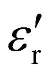 ) of 25(±4) to 29 and permeability (
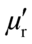 ) of 1. 5(±0.2), along with imaginary values of permittivity (
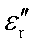 ) of 2(±1) and permeability (
 ) of 0.4(±0.1). Based on these values, the microwave absorption was determined as the Reflection Loss (RL) from the input impedance of the 60 wt% CNT absorber, Zin, compared to that of air, Z0, as:137
| RL = 20log(|Zin − Z0|)/(|Zin + Z0|) | (4) |
 ), the permeability (
 ), and the thickness (d) of the CNT absorber were used to calculate the input impedance of the MWCNT absorber:137
Zin = Z0 (μr/εr)1/2 tan![[thin space (1/6-em)]](https://www.rsc.org/images/entities/char_2009.gif) h[j(2πfd/c)(μrεr)1/2] h[j(2πfd/c)(μrεr)1/2]
| (5) |
The microwave absorption of the metal loaded MWCNTs ranged from RL = −37 db for Ni and Co to RL = −39 db for Fe. For appropriate thin 1 to 10 mm MWCNT layers, the microwave absorption remains high in the 1 through 7 GHz microwave range. In that study, the epoxy confined CNTs did not induce a plasma. However here instead with MWCNTs made from CO2, such a large microwave power coupling confined in a small thickness is consistent with the formation of CNT hotspots in direct contact with the borosilicate, which were observed to induce a stable plasma. With high, broad band microwave coupling and power absorption, these CNTs made can be useful for a range of electromagnetic and thermal applications including not only plasma induction, but also heating, heat transfer, and shielding over a large frequency range.
CNT-induced microwave-plasma self-purification of CNTs
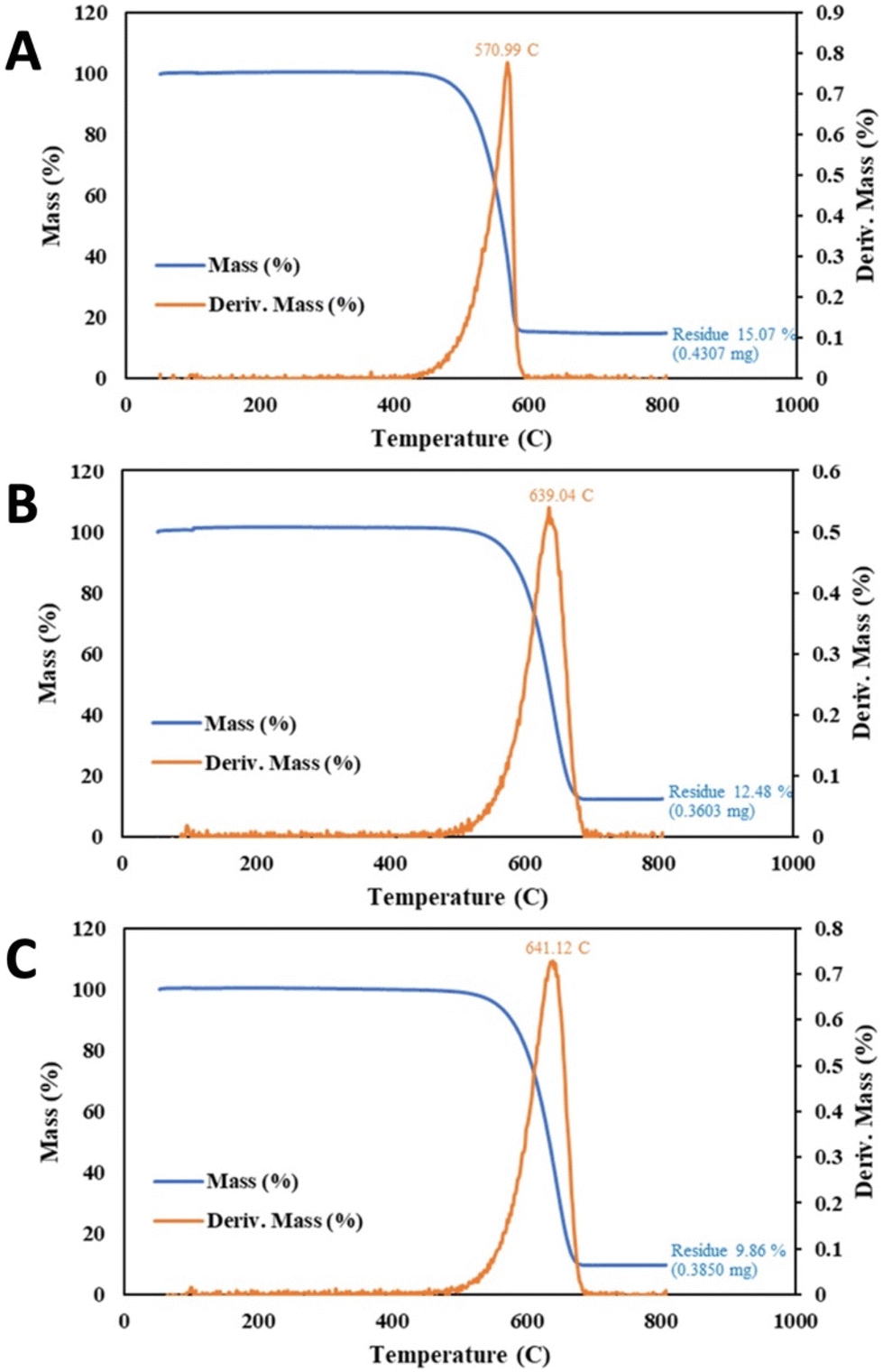
As one application of the efficient, spatially constrained CNT-induced microwave-driven plasma, this section presents the plasmas' utility in purification of the CNTS. Purification is accomplished with one to two orders of magnitude lower plasma power or time than a conventional bench-top plasma designed for cleaning. Molten carbonate CNTs synthesized by CO2 splitting retain, post-electrolysis impurities, consisting of metals, electrolyte, and amorphous carbons that can be significantly removed by plasma treatment and washing. The plasma can expose and/or oxidize impurities, and the washing can remove solid plasma purification products (those that were not volatilized during the plasma application). A C2CNT product with high impurity level was chosen as shown in Fig. 6A. For these purification experiments, the product was prepared with CO2 directly from the air, with an 840 cm2 brass electrode, electrolytically split for 3 hours at current density of J = 0.2 A cm−2 in 780 °C Li2CO3. Useful measures of the CNT product impurity are the TGA mass (%) of the product at 800 °C and the TGA inflection temperature, TGAinfl.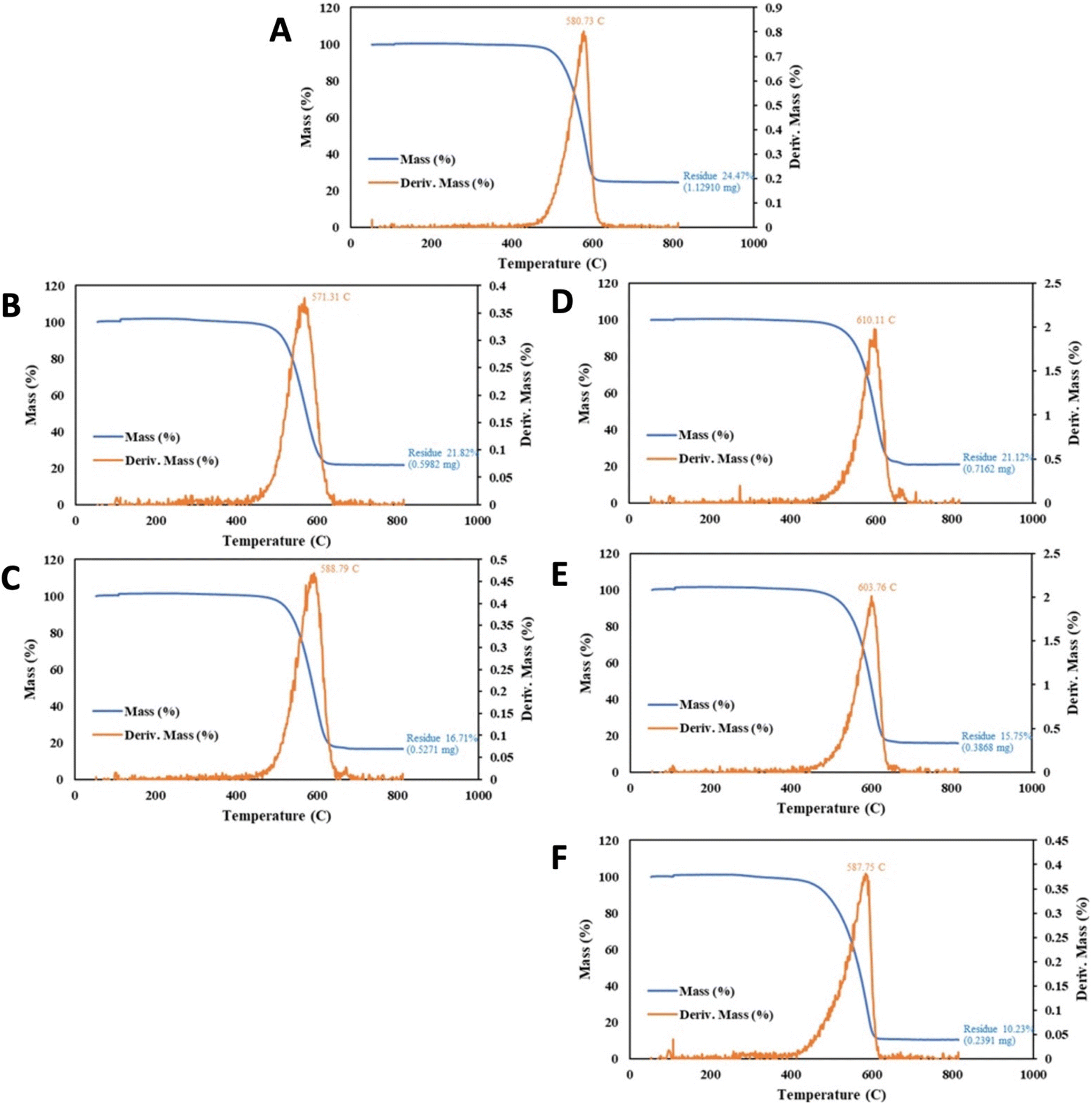 | ||
| Fig. 6 CNT from CO2 product before, and after, various plasma treatments. The product is from a 770 °C Li2CO3 3 hour electrolysis, conducted at J = 0.2 A cm−2 with an SS304 anode at an 840 cm2 area brass cathode. (A) TGA of the extracted, washed C2CNT product prior to plasma purification content. (B and C) TGA of the product after 1 (B) or 4 hours (C) of conventional plasma cleaning and wash in 80%/20% HCl/H2O2 at 95 °C for 4 hours. (D to F) TGA of the product instead after CNT-induced microwave-driven plasma at powers of either 340 W (D), 3200 W (E), or 650 W (F), and washed with either 80%/20% HCl/H2O2 (D and E) or 64%/16%/20% HCl/HNO3/H2O2 (F) at 95 °C for 4 hours. | ||
As can be seen in each of the TGA in Fig. 6, the mass reduction with heating falls to a plateau at T > 700 °C. In the case of Fig. 6A resulting in a TGAmeasured purity = 75.5% (100% − the measured residue). The 24.5% TGA residual mass, is comprised approximately 1/3 of O2 mass accumulated during the TGA heating under air. This accumulates as oxide formed during the combustion process. Hence, the actual TGA residue is approximately 16%, and the purity is approximately TGAactual = 84%.
The inflection temperature is a measure of the product's resistance to oxidation Amorphous carbon typically exhibits TGAinfl = ∼300 °C, while higher quality graphene nanocarbons exhibit TGAinfl > ∼580 °C, and in this case, Fig. 6A panel, TGAinfl = 571 °C.
A decrease in CNT product impurities is probed by a lowering of the >700 °C mass loss plateau in the blue curve in the TGA, and a shift to the right of Tinfl is indicative of greater oxidation resistance. The Fig. 6A CNT from CO2 sample is placed in a standard air plasma cleaner at maximum power (300 W) for 1 hour and then washed with 80%/20% HCl/H2O2 at 95 °C for 4 hours. We have observed this combined wash is more effective than either or HCl or H2O2 alone, and that 95 °C is more effective than a room-temperature wash. As seen in Fig. 6, this increases the TGAmeasured, to 78.2%, although Tinfl decreases to 571 °C. However, as seen with an increase to 4 hours of plasma treatment in Fig. 6C, followed by the same post-plasma wash, the CNT purity improves with TGAmeasured, to 83.3%, and Tinfl increases to 589 °C and SEM purity to 80 to 85%. Without the wash, some plasma-treated impurities remain on the CNTs. For example (not shown in Fig. 6), unwashed 4 hour plasma values respectively had TGAmeasured = 75.5%, and Tinfl = 583 °C.
The CNT-induced microwave-driven plasma purifies CNTs more quickly and with less energy than a conventional plasma. Rather than a conventional plasma clean in which the plasma is formed throughout the cleaning chamber, the CNT from CO2-induced microwave-driven plasma forms, and is spatially constrained, at the point of cleaning. The result is that the same degree of CNT plasma purification occurs with an order of magnitude less power or time.
As shown in Fig. 6D, 340 W CNT-induced microwave-driven plasma produces the same extent of purification (TGAmeasured = 78.9%) in 1 minute as 1 hour of the conventional 300 W applied plasma (using the same post-washing conditions), and results in an increase in Tinfl to 610 °C. As shown in Fig. 6E, a similar, but higher powered, 3200 W microwave plasma produces greater purification (TGAmeasured = 84.3%) in 1 min as 4 hours of the conventional 300 W plasma, with a good, but lower, Tinfl = 604 °C. An excess of plasma treatment may continue to lower the residual impurity, but also may be detrimental to the CNT Tinfl.
Intermediate levels of microwave irradiation, either 650 W or 1600 W of CNT-induced microwave-driven plasma, result in intermediate increases in CNT purity respectively of TGAmeasured = 81.1% and 83.0%. As with the 340 W purification, 650 W 1 minute of microwave irradiation appears to be less aggressive than the 3200 W purification treatment, resulting in a higher Tinfl = 620 °C, albeit achieving a lower level of impurity removal with TGAmeasured = 81.1% than the 3200 W purification treatment.
As shown in Table 1, alternative post-microwave washes than the 80%/20% HCl/H2O2 have been investigated. A nitric acid clean of the 650 W irradiate CNTs results in a modestly improved impurity decrease, but is more aggressive with lower Tinfl improvements. However as seen in Fig. 6F, a 64%/16%/20% HCl/HNO3/H2O2 post microwave wash at 95 °C for 4 hours, further decreases TGA measured impurities resulting in TGAmeasured = 89.8, with a drop in Tinfl = 588 °C.
| CNT from CO2 sample | Wash | TGA% | Tinfl °C |
|---|---|---|---|
| Base CNT | Pre | 75.4 | 581 |
| 4 h 300 W standard plasma | None | 75.5 | 583 |
| 4 h 300 W standard plasma | A | 83.3 | 589 |
| 1 h 300 W standard plasma | A | 78.2 | 571 |
| 1 min 3200 W MW plasma | A | 84.3 | 603 |
| 1 min 1600 W MW plasma | A | 83.0 | 599 |
| 1 min 650 W MW plasma | A | 81.1 | 620 |
| 1 min 340 W MW plasma | A | 78.9 | 610 |
| 1 min 650 W MW plasma | HNO3 | 81.8 | 615 |
| 1 min 650 W MW plasma | B | 78.5 | 593 |
| 1 min 650 W MW plasma | C | 77.4 | 610 |
| 1 min 650 W MW plasma | D | 83.0 | 590 |
| 1 min 650 W MW plasma | E | 89.8 | 573 |
| 1 min 650 W MW plasma | F | 88.7 | 579 |
| 1 min 650 W MW plasma | G | 89.8 | 588 |
Starting with a higher base purity sample of TGAmeasured = 84.9% rather than 75.4% in the previous example, 1 minute of reduced power CNT-induced microwave-plasma, coupled with an extend wash time further improved the CNT as summarized in Fig. 7. Specifically, compared to the new base sample, the one minute of 650 W CNT-induced microwave plasma with 1 hour of 75%/25% HCl/H2O2 results in TGAmeasured = 87.5.2% and Tinfl = 639 °C, compared to 325 W of microwave power and 24 hours with the same post wash yielding an improved of TGAmeasured = 90.1% and Tinfl = 641 °C.
 | ||
| Fig. 7 CNT from CO2 product before, and after, various plasma treatments. The product is from a 770 °C Li2CO3 16 hour electrolyte. Conducted at J = 0.2A cm−2 with a stainless steel 304 anode at a 1020 cm2 area brass cathode. (A) TGA of the extracted, washed C2CNT product prior to plasma purification content. (B and C) The product after CNT-induced microwave-driven plasma and washed in 75%/25% HCl/H2O2. (B) TGA subsequent to 650 W applied microwave with a 1 hour of wash. (C) TGA subsequent to 325 W applied microwave with a 24 hour wash. | ||
With still higher base purity sample of TGAmeasured = 89.7%, 4 hours of conventional 300 W plasma cleaning was again outperformed by 1 minute of 650 W CNT-induced microwave-plasma as summarized in Fig. 8. Specifically, compared to the base sample, the 4 hour plasma increased TGAmeasured to 93.8% and increase of Tinfl from 614 to 620 °C (again with a 4 hour 95 °C 80%/20% HCl/H2O2 post wash). Better was the one minute of CNT-induced microwave plasma with the same post wash, exhibiting TGAmeasured = 95.2% and a Tinfl = 668 °C.
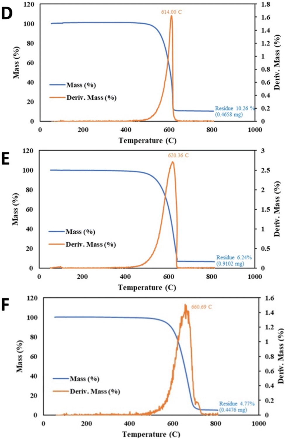 | ||
| Fig. 8 CNT from CO2 product before, and after, various plasma treatments. The product is from a 770 °C Li2CO3 18 hour electrolyte. Conducted at J = 0.4 A cm−2 with a stainless steel 304 anode at a 663 cm2 area brass cathode. (D) TGA of the extracted, washed C2CNT product prior to plasma purification content. (E) TGA of the product after 4 hours of conventional plasma cleaning and wash in 75%/25% HCl/H2O2. (F) TGA of the product instead after CNT-induced microwave-driven plasma at powers of 650 W and washed similarly. | ||
A higher base purity sample of TGAmeasured = 95.0% and Tinfl = 614 °C required higher power coupled with lower irradiation time to achieve the highest purity as seen in Fig. 9. Specifically, 10 minutes of 325 W CNT-induced microwave-plasma with an HCl wash was outperformed by 1 min at 650 W power with the same, again with an HCl wash. Compared to the base sample, the 10 minute CNT-induced microwave plasma overpowered the sample decreasing the TGAmeasured to 93.8%, although Tinfl improved to 620 °C. Better was the one minute of CNT-induced microwave plasma at twice the power, exhibiting TGAmeasured = 96.7%, and Tinfl = 667 °C.
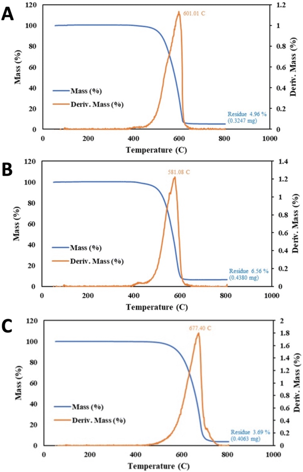 | ||
| Fig. 9 CNT from CO2 product before and after, various microwave-driven plasma treatments. The product is from a 770 °C Li2CO3 18 hour electrolyte. Conducted at J = 0.4 A cm−2 with a stainless steel 304 anode at a 663 cm2 area brass cathode. (A) TGA of the extracted, washed C2CNT product prior to plasma purification content. (B) TGA of the product after 4 hours of conventional plasma cleaning and wash in 75%/25% HCl/H2O2. (C) TGA of the product instead after CNT-induced microwave-driven plasma at powers of 650 W and similarly washed. | ||
Incentivized carbon mitigation
The development of intense, self-induced, sustainable microwave plasma for producing carbon nanotubes from CO2 represents a significant advancement in the realm of GNCs, offering low energy consumption, minimal carbon footprint, and cost-effectiveness. Current commercial costs for GNCs such as CNTs, CNOs, and graphene are prohibitively high due to the substantial energy, material, and carbon emissions associated with CVD production.68,138 In comparison, the C2CNT (CO2 to Carbon NanoMaterial Technology) process requires only CO2 as a feedstock, with electrolysis energy needs ranging from 0.8 to 2 V for transforming CO2 into GNCs.139 This results in C2CNT GNC production costs being up to three orders of magnitude lower than those of CVD methods, typically around $1000 per ton in bulk.70 This cost structure is comparable to industrial electrolytic processes that produce commercial-grade aluminium from aluminium oxide.98 Furthermore, C2CNT costs can be reduced to a greater extent when powered by renewable energy sources such as solar and wind.140–146Current applications of cold/warm plasmas
Cold and warm plasmas, also termed dusty or complex plasmas, are non-thermal equilibrium plasmas, including not only free ions and electrons but also species that have not been ionized. While thermal (hot) plasmas maintain a high enough thermal energy to remain in the plasma state, non-thermal plasmas require an external power source, to remain in the plasma state.135–140 Here, the borderline distinguishing cold and warm plasmas is considered 800–1000 °C, although the literature describes a broad range of alternative nonthermal plasma temperature ranges.147–153 This places the 850–950 °C CNT triggered and sustained in this study as applicable to both cold and warm plasma applications. Such non-thermal plasmas have a variety of applications, providing an energetic nature without many of the disadvantages attributed to hot plasmas.145–150 A hot plasma energy is often harder to generate, contain, and extinguish than cold or warm plasma.149–153 It should be noted that in one electron beam case, Masoud et applied 13–18 kV, not microwave radiation, to induce CNTs to act as electron emitters to generate an electron beam, which formed a near UV plasma in air. The novel microwave CNT-induced plasma in this communication does not require high voltage. The microwave configuration and using CNTs to induce the plasma is straightforward and appears more amenable to scale-up.Some uses of non-hot plasma are as follows. Non-hot plasmas have been extensively used to break up or ionize material for characterization purposes without breaking up material too much, requiring low energy, and not making more exotic species that can interfere with instruments, esp. for ICP-MS.145,146 Non-hot plasmas have been used to disinfect a wide variety of surfaces, clean wounds from pathogens, kill cancer cells or specific cell types in the body, promote stem cell or blood vessel growth, and promote blood flow; along, with waste treatment from wastewater to sludge to pyrolysis chamber to make gasses; and food sanitation.148–161 Non-hot plasma have been used to bond dental and other medical materials.149–152 Non-hot plasma has been used to sterilize metal without diminishing sharpness which is much better for items like surgical equipment or very locally hardened metal surfaces.153 Non-hot plasma has been used to clean chip, metal, and textile fibers’ surfaces; roughen or polish polymers or metal surfaces; surface modify numerous polymers, metals, and textiles while saving energy and lowering pollutants emitted.154–157 It has also been used to make plasma shields from microwave or other EM waves, reduce drag, and act as a heat shield, a window that can be opened/closed, or accelerate or trap ions or particles such as for some small rocket thruster.157–161 Lastly, it has been used to chemically reduce gasses.26,44,147,148,151
Conclusions
An unexpected and high-powered plasma is induced by carbon nanotubes in air under microwave irradiation. Specifically, the phenomenon is observed with CNTs made from the greenhouse gas CO2 split by molten carbonate electrolysis and transformed into graphene nanocarbons. The phenomenon is not observed with CNTs made by CVD, and it is hypothesized that this is due to the characteristic of the molten carbonates of the growth process including transition metal nucleation, increased electron mobility and previously introduced magnetic properties. The high aspect ratio and concentric graphene cylinder morphology of all CNTs, has previously been observed to intensify related electron field emission. The CNT-induced microwave-driven plasma observed here is observed to be intense, spatially constrained, and makes efficient use of the microwave irradiation power. Several potential applications of this new method of intense plasma induction are discussed, and a single application is studied in depth. This application, the plasma purification of CNTs to decrease their impurity level and increase their resistance to combustion, is demonstrated to require 100-fold less time, consume 10× less power, and produce higher purity CNTs than purification in a conventional plasma cleaning treatment chamber.Data availability
The data supporting this article have been included as part of the ESI.†Conflicts of interest
There are no conflicts to declare.Acknowledgements
We are grateful to Molood Nasirikheirabadi of Carbon Corp for experimental contributions.References
- H. K. Khattak, P. Bianucci and A. D. Slepkov, Linking plasma formation in grapes to microwave resonances of aqueous dimers, Proc. Natl. Acad. Sci. U. S. A., 2019, 116, 4000–4005, DOI:10.1073/pnas.1818350116.
- J. B. Donnet, S. J. Park and M. Brendle, The effect of microwave plasma treatment on the surface energy of graphite as measured by inverse gas chromatography, Carbon, 1992, 30, 263–268, DOI:10.1016/0008-6223(92)90089-f.
- Y. F. Li, S. F. Zhu and Y. An, Selectivity heating effect of Microwave on purifying of natural graphite, Appl. Mech. Mater., 2012, 174–177, 810–815, DOI:10.4028/www.scientific.net/AMM.174-177.810.
- S. Chandrasekaran, T. Basak and R. Srinivasan, Microwave heating characteristics of graphite based powder mixtures, Int. Commun. Heat Mass Transfer, 2013, 48, 22–27, DOI:10.1016/j.icheatmasstransfer.2013.09.008.
- S. M. Cruz, G. T. Druzian, R. F. Santos, M. F. Mesko, F. A. Duarte and E. M. M. Flores, Microwave-induced self-ignition: An efficient approach for high purity graphite digestion and multitechnique halogen determination, Anal. Chim. Acta, 2022, 1199, 339569, DOI:10.1016/j.aca.2022.339569.
- J. E. Omoriyekomwan, A. Tahmasebi, J. Dou, R. Wang and J. Yu, A review on the recent advances in the production of carbon nanotubes and carbon nanofibers via microwave-assisted pyrolysis of biomass, Fuel Process. Technol., 2021, 214, 106686, DOI:10.1016/j.fuproc.2020.106686.
- A. M. Schwenke, S. Hoeppener and U. S. Schubert, Synthesis and Modification of Carbon Nanomaterials utilizing Microwave Heating, Adv. Mater., 2015, 27, 4113–4141, DOI:10.1002/adma.201500472.
- X. Chen, H. Liu, D. Hu, H. Liu and W. Ma, Recent advances in carbon nanotubes-based microwave absorbing composites, Ceram. Int., 2021, 47, 23749–23761, DOI:10.1016/j.ceramint.2021.05.219.
- C. Xu, X. Xiao, C. Cai, Q. Cheng, L. Zhu, J. Zhang, B. Wei and H. Wang, Insight into the differences in carbon dots prepared from fish scales using conventional hydrothermal and microwave methods, Environ. Sci. Pollut. Res., 2023, 30, 54616–54627, DOI:10.1007/s11356-023-26275-z.
- R. Bajpai and H. D. Wagner, Fast growth of carbon nanotubes using a microwave oven, Carbon, 2015, 82, 327–336, DOI:10.1016/j.carbon.2014.10.077.
- C. Su, H. Chen, C. Chen, J. Yao, H. Chen and C. Chang, et al., Improving the adhesion of carbon nanotubes to a substrate using microwave treatment, Carbon, 2010, 48, 805–812, DOI:10.1016/j.carbon.2009.10.032.
- J. Lin, Y. Huang, S. Wang and G. Chen, Microwave-assisted rapid exfoliation of graphite into graphene by using ammonium bicarbonate as the intercalation agent, Ind. Eng. Chem. Res., 2017, 56, 9341–9346, DOI:10.1021/acs.iecr.7b01302.
- A. R. Harutyunyan, B. K. Pradhan, G. U. Sumanasekera, J. Chang, G. Chen, H. Goto, J. Fujiwara and P. C. Eklund, Purification of SWNTs Using Microwave Heating, MRS Proc., 2001, 706, 201, DOI:10.1557/PROC-706-Z2.8.1.
- C. Ko, Highly efficient microwave-assisted purification of multiwalled carbon nanotubes, Microelectron. Eng., 2004, 73–74, 570–577, DOI:10.1016/j.mee.2004.02.087.
- C.-M. Chen, M. Chen, F.-C. Leu, S.-Y. Hsu, S.-C. Wang, S.-C. Shi and C.-F. Chen, Purification of multi-walled carbon nanotubes by microwave digestion method, Diamond Relat. Mater., 2004, 13, 1182–1186, DOI:10.1016/j.diamond.2003.11.016.
- F.-H. Ko, C.-Y. Lee, C.-J. Ko and T.-C. Chu, Purification of multi-walled carbon nanotubes through microwave heating of nitric acid in a closed vessel, Carbon, 2005, 43, 727–733, DOI:10.1016/j.carbon.2004.10.042.
- Y. Ji, T. Li, L. Zhu, X. Wang and Q. Lin, Preparation of activated carbons by microwave heating KOH activation, Appl. Surf. Sci., 2007, 254, 506–512, DOI:10.1016/j.apsusc.2007.06.034.
- K. R. Paton and A. H. Windle, Efficient microwave energy absorption by carbon nanotubes, Carbon, 2008, 46, 1935–1941, DOI:10.1016/j.carbon.2008.08.001.
- T. Kim, J. Lee and K.-H. Lee, Microwave heating of carbon-based solid materials, Carbon Lett., 2014, 15, 15–24, DOI:10.5714/CL.2014.15.1.015.
- K. MacKenzie, O. Dunens and A. T. Harris, A review of carbon nanotube purification by microwave assisted acid digestion, Sep. Purif. Technol., 2009, 66, 209–222, DOI:10.1016/j.seppur.2009.01.017.
- W. Lin, K.-S. Moon, S. Zhang, Y. Ding, J. Shang, M. Chen and C. Wong, Microwave Makes Carbon Nanotubes Less Defective, ACS Nano, 2010, 4, 1716–1722, DOI:10.1021/nn901621c.
- A. Amiri, M. Maghrebi, M. Baniadam and S. Zeinali Heris, One-pot, efficient functionalization of multi-walled carbon nanotubes with diamines by microwave method, Appl. Surf. Sci., 2011, 257, 10261–10266, DOI:10.1016/j.apsusc.2011.07.039.
- R. Pelalak, M. Baniadam and M. Maghrebi, Controllable purification, cutting and unzipping of multi-walled carbon nanotubes with a microwave method, Appl. Phys. A, 2012, 111, 951–957, DOI:10.1007/s00339-012-7320-9.
- K. Y. Foo and B. H. Hameed, Microwave-assisted regeneration of activated carbon, Bioresour. Technol., 2012, 119, 234–240, DOI:10.1016/j.biortech.2012.05.061.
- J. Alandari, A. M. Diamy, J. M. Guillerme, J. C. Legrand and R. I. Ben-Aim, Rotational Temperature in Helium, Argon, and Oxygen Microwave-Induced Plasmas: Comparison with Translational and Solid Surface Temperatures, Appl. Spectrosc., 1989, 43, 681–687, DOI:10.1366/0003702894202490.
- F. A. D'Isa, E. A. Carbone, A. Hecimovic and U. Fantz, Performance analysis of a 2.45 GHz microwave plasma torch for CO2 decomposition in gas swirl configuration, Plasma Sources Sci. Technol., 2020, 29, 105009, DOI:10.1088/1361-6595/abaa.
- J. Alandari, A. M. Diamy, J. M. Guillerme, J. C. Legrand and R. I. Ben-Aim, Rotational Temperature in Helium, Argon, and Oxygen Microwave-Induced Plasmas: Comparison with Translational and Solid Surface Temperatures, Appl. Spectrosc., 1989, 43, 681–687, DOI:10.1366/0003702894202490.
- B. K. Barnes, H. Ouro-Koura, J. Derickson, S. Lebarty, J. Omidokun, N. Bane, O. Suleiman, E. Omagamre, M. J. Fotouhi, A. Ogunmolasuyi, A. Dominguez, L. Gonick and K. S. Das, Plasma generation by household microwave oven for surface modification and other emerging applications, Am. J. Phys., 2021, 89, 372–382, DOI:10.1119/10.0002706.
- H. Zhu, Y. Huang, S. Yin and W. Zhang, Microwave plasma setups for CO2 conversion: A mini-review, Green Energy Resour., 2024, 2, 100061, DOI:10.1016/j.gerr.2024.100061.
- Y. Liu, J. He, N. Zhang, W. Zhang, Y. Zhou and K. Huang, Advances of microwave plasma-enhanced chemical vapor deposition in fabrication of carbon nanotubes: a review, J. Mater. Sci., 2021, 56, 12559–12583, DOI:10.1007/s10853-021-06128-1.
- D. Li and L. Tong, Direct Growth of Carbon Nanotubes on Aluminum Foil by Atmospheric Pressure Microwave Plasma Chemical Vapor Deposition, Processes, 2020, 9, 36, DOI:10.3390/pr9010036.
- L. C. Qin, D. Zhou, A. R. Krauss and D. M. Gruen, Growing carbon nanotubes by microwave plasma-enhanced chemical vapor deposition, Appl. Phys. Lett., 1998, 72, 3437–3439, DOI:10.1063/1.121658.
- Y. Liu, J. He, N. Zhang, W. Zhang, Y. Zhou and K. Huang, Advances of microwave plasma-enhanced chemical vapor deposition in fabrication of carbon nanotubes: a review, J. Mater. Sci., 2021, 56, 12559–12583, DOI:10.1007/s10853-021-06128-1.
- Y. Liu, N. Guo, P. Yin and C. Zhang, Facile growth of carbon nanotubes using microwave ovens: the emerging application of highly efficient domestic plasma reactors, Nanoscale Adv., 2019, 1, 4546–4559, 10.1039/c9na00538b.
- A. Zainul, M. F. Alif and R. Mulyasuryani, Advancements in plasma-enhanced chemical vapor deposition of a multi-walled carbon nanotubes on Si/SiO2 substrates: A comprehensive review, J. Med. Pharm. Chem. Res., 2023, 5, 1013–1033, DOI:10.48309/jmpcr.2023.417750.1007.
- A. Abdelhalim, A. Abdellah, G. Scarpa and P. Lugli, Fabrication of carbon nanotube thin films on flexible substrates by spray deposition and transfer printing, Carbon, 2013, 61, 72–79, DOI:10.1016/j.carbon.2013.04.069.
- Z. Wu, Y. Xu, X. Zhang, G. Shen and R. Yu, Microwave plasma treated carbon nanotubes and their electrochemical biosensing application, Talanta, 2007, 72, 1336–1341, DOI:10.1016/j.talanta.2007.01.052.
- Z. Wang, H. Ogata, S. Morimoto, J. Ortiz-Medina, M. Fujishige, K. Takeuchi, H. Muramatsu, T. Hayashi, M. Terrones, Y. Hashimoto and M. Endo, Nanocarbons from Rice Husk by Microwaves Plasma Irradiation: From Graphene and Carbon Nanotubes to Graphenated Carbon Nanotube Hybrids, Carbon, 2015, 94, 479–484, DOI:10.1016/j.carbon.2015.07.037.
- J. Zheng, R. Bao, J. Yi and P. Yang, Microwave Purification of Multi-Wall Carbon Nanotubes in Gas Phase, Diamond Relat. Mater., 2016, 68, 93–101, DOI:10.1016/j.diamond.2016.06.006.
- M. Saeed, R. Sami, U. Haq, S. Ahmed, F. Siddiqui and J. Yi, Recent advances in carbon nanotubes, graphene and carbon fibers-based microwave absorbers, J. Alloys Compd., 2024, 970, 172625, DOI:10.1016/j.jallcom.2023.172625.
- Y. R. Poudel and W. Li, Synthesis, Properties, and Applications of Carbon Nanotubes Filled with Foreign Materials: A Review, Mater. Today Phys., 2018, 7, 7–34 CrossRef.
- A. Gharpure, V. Viswanathan, A. Mantri, G. Skoptsov and R. L. Vander Wal, Graphitizable Pitch from Microwave Plasma Pyrolysis of Natural Gas, ACS Omega, 2024, 9, 14351–14355, DOI:10.1021/acsomega.3c10428.
- S. Marinov, I. Ivanov, G. Popov, M. Abrashev and Z. Kiss'ovski, Deposition of vertical carbon nanostructures by microwave plasma source on nickel and alumina, J. Phys.:Conf. Ser., 2024, 2710, 012002, DOI:10.1088/1742-6596/2710/1/012002.
- Y.-D. Lim, D.-Y. Lee, T.-Z. Shen, C.-H. Ra, J.-Y. Choi and W. J. Yoo, Si-Compatible Cleaning Process for Graphene Using Low-Density Inductively Coupled Plasma, ACS Nano, 2012, 6, 4410–4417, DOI:10.1021/nn301093h.
- D. Ferrah, O. Renault, C. Petitäêetienne, H. Okuno, C. Berne, V. Bouchiat and G. Cunge, XPS investigations of graphene surface cleaning using H2- and Cl2-based inductively coupled plasma, Surf. Interface Anal., 2016, 48, 451–455, DOI:10.1002/sia.6010.
- R. Pristavita, N.-Y. Mendoza-Gonzalez, J.-L. Meunier and D. Berk, Carbon Nanoparticle Production by Inductively Coupled Thermal Plasmas: Controlling The Thermal History of Particle Nucleation, Plasma Chem. Plasma Process., 2011, 31, 851–866 CrossRef CAS.
- P. Kumar, Pressure-Dependent Synthesis of High-Quality Few-Layer Graphene by Plasma-Enhanced Arc Discharge and Their Thermal Stability, J. Nanopart. Res., 2013, 15, 1847 CrossRef.
- B. Li, Y. Nan, Z. Peng, Z. Wang, Q. Lu and X. Song, Synthesis and Characterization of Carbon Nanostructures by Evaporating Pure Graphite and Carbon Black in Detonation-Gas Arc Discharge, Diamond Relat. Mater., 2015, 55, 87–94 CrossRef CAS.
- D. L. Sun, R. Y. Hong, J. Y. Liu, F. Wang and Y. F. Wang, Preparation of Carbon Nanomaterials Using Two-Group Arc Discharge Plasma, Chem. Eng. J., 2016, 303, 217–230 CrossRef CAS.
- F. Weng and R. Hong, Continuous Preparation of Structure-Controlled Carbon Nanoparticle Via Arc Plasma and The Reinforcement of Polymeric Composites, Chem. Eng. J., 2017, 328, 1098–1111 CrossRef.
- H. S. Kwak, H. S. Uhm, Y. C. Hong and E. H. Choi, Disintegration of Carbon Dioxide Molecules in a Microwave Plasma Torch, Sci. Rep., 2015, 5, 18436, DOI:10.1038/srep18436.
- S. W. Ham, H. P. Hong, J. H. Kim, S. J. Min and N. K. Min, Effect of Oxygen Plasma Treatment on Carbon Nanotube-Based Sensors, J. Nanosci. Nanotechnol., 2014, 14, 8476–8481, DOI:10.1166/jnn.2014.10007.
- S. Li, Y. Liu, S. Zhou, C. Zhou and M. Chan, Contact Resistance Reduction of Carbon Nanotube Via through O2 Plasma Post-Synthesis Treatment, J. Mater. Chem. C, 2018, 6, 5039–5045, 10.1039/C8TC00770E.
- C.-T. Lo, K.-W. Lin, T.-P. Wang, S.-M. Huang and C.-L. Lee, Differentiating between the effects of nitrogen plasma and hydrothermal treatment on electrospun carbon fibers used as supercapacitor electrodes, Electrochim. Acta, 2021, 381, 138255, DOI:10.1016/j.electacta.2021.138255.
- M. V. Naseh, A. A. Khodadadi, Y. Mortazavi, F. Pourfayaz, O. Alizadeh and M. Maghrebi, Fast and clean functionalization of carbon nanotubes by dielectric barrier discharge plasma in air compared to acid treatment, Carbon, 2010, 48, 1369–1379, DOI:10.1016/j.carbon.2009.12.027.
- A. Dato, Graphene synthesized in atmospheric plasmas—A review, J. Mater. Res., 2019, 34, 214–230, DOI:10.1557/jmr.2018.470.
- B. Ruelle, C. Bittencourt and P. Dubois, 2 - Surface treatment of carbon nanotubes via plasma technology, Polym.-Carbon Nanotube Compos., 2011, 25–54, DOI:10.1533/9780857091390.1.25.
- R. Scaffaro, A. Maio, S. Agnello and A. Glisenti, Plasma Functionalization of Multiwalled Carbon Nanotubes and Their Use in the Preparation of Nylon 6-Based Nanohybrids, Plasma Processes Polym., 2012, 9, 503–512, DOI:10.1002/ppap.201100140.
- R. R. Kumal, A. Gharpure, V. Viswanathan, A. Mantri, G. Skoptsov and R. Vander Wal, Formation of Carbon Nanostructures by The Plasma Jets: Synthesis, Characterization, Application, Mater. Today: Proc., 2018, 5, 25956–25961 Search PubMed.
- N. Peltekis, S. Kumar, N. McEvoy, K. Lee, A. Weidlich and G. S. Duesberg, The effect of downstream plasma treatments on graphene surfaces, Carbon, 2012, 50, 395–403, DOI:10.1016/j.carbon.2011.08.052.
- A. Dey, A. Chroneos, N. St. Braithwaite, R. P. Gandhiraman and S. Krishnamurthy, Plasma engineering of graphene, Appl. Phys. Rev., 2016, 3, 021301, DOI:10.1063/1.4947188.
- D. C. Elias, R. R. Nair, T. M. Mohiuddin, S. V. Morozov, P. Blake, M. P. Halsall, A. C. Ferrari, D. W. Boukhvalov, M. I. Katsnelson, A. K. Geim and K. S. Novoselov, Control of Graphene's Properties by Reversible Hydrogenation: Evidence for Graphane, Science, 2009, 323, 610–613, DOI:10.1126/science.116713.
- K. P. Loh, Q. Bao, P. K. Ang and J. Yang, The chemistry of graphene, J. Mater. Chem., 2010, 20, 2277, 10.1039/B920539J.
- R. Kumar, R. Singh, P. Dubey, P. Kumar, R. Tiwari and I.-K. Oh, Pressure-Dependent Synthesis of High-Quality Few-Layer Graphene by Plasma-Enhanced Arc Discharge and Their Thermal Stability, J. Nanopart. Res., 2013, 15, 1847 CrossRef.
- R. Amirov, M. Shavelkina, N. Alikhanov, N. E. Школьников, A. Tyuftyaev and N. Vorob'eva, Direct Synthesis of Porous Multilayer Graphene Materials Using Thermal Plasma at Low Pressure, J. Nanomater., 2015, 724508 CrossRef.
- Z. Xiao, Q. Wan and C. Durkan, Cleaning Transferred Graphene for Optimization of Device Performance, Adv. Mater. Interfaces, 2019, 6, 1801794, DOI:10.1002/admi.201801794.
- R. Snoeckx and A. Bogaerts, Plasma technology – a novel solution for CO2 conversion?, Chem. Soc. Rev., 2017, 46, 5805–5863, 10.1039/C6CS00066E.
- K. A. Shah and B. A. Tali, Synthesis of carbon nanotubes by catalytic chemical vapor deposition: A review on carbon sources, catalysts and substrates, Mater. Sci. Semicond. Process., 2016, 41, 67–82, DOI:10.1016/j.mssp.2015.08.013.
- C. Deng, W. Zhang, Y. Yang, Z. Gao, J. Wang and X. Wei, Preparation and microwave absorption properties of magnetic carbon nano-onion matrix composites, Carbon, 2019, 150, 551, DOI:10.1016/j.carbon.2019.04.096.
- P. Wang, Q. Dong, C. Gao, W. Bai, D. Chu and Y. He, A comprehensive review of carbon nanotubes: growth mechanisms, preparation and applications, Fullerenes, Nanotubes Carbon Nanostruct., 2023, 32, 415–429, DOI:10.1080/1536383X.2023.2292694.
- F. Daili, Z. Feng, Z. Zihao, P. Pe, Y. Li, Z. Jie, H. Jiankai, Z. Yuanying and F. Yanhui, Multifunctional performance of carbon nanotubes in thermal energy storage materials, Mater. Today, 2024, 75, 285–308, DOI:10.1016/j.mattod.2024.04.005.
- N. Dhama, et al., Carbon nanotubes: current applications, structural insights and future prospects, Biochem. Cell. Arch., 2024, 24, 463, DOI:10.51470/bca.2024.24.1.463.
- Carbon nanotube based sensors, ed. A. Nag and A. Mukherjee, CRC Press, Boca Raton, 2024. DOI:10.1201/9781003376071.
- Z. Ali, S. Yaqoob, J. Yu and A. D'Amore, Critical review on the characterization, preparation, and enhanced mechanical, thermal, and electrical properties of carbon nanotubes and their hybrid filler polymer composites for various applications, Compos., Part C: Open Access, 2024, 13, 100434, DOI:10.1016/j.jcomc.2024.100434.
- M. D'Amore, M. S. Sarto and A. G. D'Aloia, Skin-Effect Modeling of Carbon Nanotube Bundles: The High-Frequency Effective Impedance, 2010 IEEE International Symposium on Electromagnetic Compatibility, 2010. DOI:10.1109/ISEMC.2010.5711390.
- A. Lekawa-Raus, J. Patmore, L. Kurzepa, J. Bulmer and K. Koziol, Electrical Properties of Carbon Nanotube Based Fibers and Their Future Use in Electrical Wiring, Adv. Funct. Mater., 2014, 24, 3661–3682, DOI:10.1002/adfm.201303716.
- J. S. Bulmer, A. Kaniyoor and J. A. Elliott, A Meta-Analysis of Conductive and Strong Carbon Nanotube Materials, Adv. Mater., 2021, 33, 2008432, DOI:10.1002/adma.202008432.
- B. Marinho, M. Ghislandi, E. Tkalya, C. E. Koning and G. de With, Electrical conductivity of compacts of graphene, multi-wall carbon nanotubes, carbon black, and graphite powder, Powder Technol., 2012, 221, 351–358, DOI:10.1016/j.powtec.2012.01.024.
- Y.-Y. Shi, S.-Y. Liao, Q.-F. Wang, X.-Y. Xu, X.-Y. Wang, X.-Y. Gu, Y.-G. Hu, P.-L. Zhu, R. Sun and Y.-J. Wan, Enhancing the Interaction of Carbon Nanotubes by Metal–Organic Decomposition with Improved Mechanical Strength and Ultra–Broadband EMI Shielding Performance, Nano-Micro Lett., 2024, 16, 134, DOI:10.1007/s40820-024-01344-1.
- X. Lu, Y. Liu, L. Pichon, D. He, O. Dubrunfaut and J. Bai, Effective electrical conductivity of CNT/polymer nanocomposites, 2020 International Symposium on Electromagnetic Compatibility - EMC EUROPE, 2020. DOI:10.1109/EMCEUROPE48519.2020.9245805.
- T. W. Ebbesen, H. J. Lezec, H. Hiura, J. W. Bennett, H. F. Ghaemi and T. Thio, Electrical conductivity of individual carbon nanotubes, Nature, 1996, 382, 54–56, DOI:10.1038/382054a0.
- G. Gradoni, D. Micheli, V. Mariani Primiani, F. Moglie and M. Marchetti, Determination of the electrical conductivity of carbon/carbon at high microwave frequencies, Carbon, 2013, 54, 76–85, DOI:10.1016/j.carbon.2012.11.005.
- C. Zeng, P. Stenier, K. Chen, K. Wan, M. Dong, S. Li, C. Kocabas, M. J. Reece, D. G. Papageorgiou, A. N. Volkov, H. Zhang and E. Bilotti, Optimization of thermoelectric properties of carbon nanotube veils by defect engineering, Mater. Horiz., 2023, 10, 3601–3609, 10.1039/D3MH00525A.
- C. Zeng, P. Stenier, K. Chen, K. Wan, M. Dong, S. Li, C. Kocabas, M. J. Reece, D. G. Papageorgiou, A. N. Volkov, H. Zhang and E. Bilotti, Optimization of thermoelectric properties of carbon nanotube veils by defect engineering, Mater. Horiz., 2023, 10, 3601–3609, 10.1039/D3MH00525A.
- F. Avilés, Thermoresistivity of Carbon Nanostructures and their Polymeric Nanocomposites, Adv. Mater. Interfaces, 2023, 10, 2300218, DOI:10.1002/admi.202300218.
- F. M. de Souza, R. K. Gupta, G. Yasin and T. A. Nguyen, Plasma produced by carbon nanotube-generated electron beam, in Plasma at the Nanoscale, 2022, pp. 21–25. DOI:10.1155/2014/43789510.1016/B978-0-323-89930-7.00014-5.
- J. Ali, A. Kumar, S. Husain, S. Parveen, R. Choithrani, M. Zulfequar, Harsh and M. Husain, Enhancement of field emission properties of carbon nanotubes by ECR-Plasma Treatment, J. Nanoscale, 2014, 2014, 437895 Search PubMed.
- N. Masoud, K. Martus and D. Murnick, Carbon nanotube generated electron beam produced plasmas, Plasma Sources Sci. Technol., 2019, 28, 045010, DOI:10.1088/1361-6595/ab123e.
- L. A. Singh, G. P. Sanborn, S. P. Turano, M. L. Walker and W. J. Ready, Operation of a Carbon Nanotube Field Emitter Array in a Hall Effect Thruster Plume Environment, IEEE Trans. Plasma Sci., 2015, 43, 95–102, DOI:10.1109/TPS.2014.2357337.
- Q. Liao, Y. Yang, J. Qi, Y. Zhang, Y. Huang, L. Xia and L. Liu, High intensity, plasma-induced electron emission from large area carbon nanotube array cathodes, Appl. Phys. Lett., 2010, 96, 073109, DOI:10.1063/1.3313944.
- J. Ali, A. Kumar, S. Husain, S. Parveen, R. Choithrani, M. Zulfequar, Harsh and M. Husain, Enhancement of Field Emission Properties of Carbon Nanotubes by ECR-Plasma Treatment, J. Nanosci., 2014, 2014, 1–5, DOI:10.1155/2014/437895.
- J. Yu, Q. Zhang, J. Ahn, S. F. Yoon, Rusli, Y. J. Li, B. Gan, K. Chew and K. H. Tan, Field emission from patterned carbon nanotube emitters produced by microwave plasma chemical vapor deposition, Diamond Relat. Mater., 2001, 10, 2157–2160, DOI:10.1016/S0925-9635(01)00496-4.
- S. Licht, STEP (solar thermal electrochemical photo) generation of energetic molecules: A solar chemical process to end anthropogenic global warming, J. Phys. Chem. C, 2009, 113, 16283–16292, DOI:10.1021/jp9044644.
- S. Licht, B. Wang, S. Ghosh, H. Ayub, D. Jiang and J. Ganley, New solar carbon capture process: STEP carbon capture, J. Phys. Chem. Lett., 2010, 1, 2363–2368, DOI:10.1021/jz100829s.
- J. Ren, F.-F. Li, J. Lau, L. Gonzalez-Urbina and S. Licht, One-pot synthesis of carbon nanofibers from CO2, Nano Lett., 2015, 15, 6142–6148, DOI:10.1021/jp9044644.
- J. Ren and S. Licht, Tracking airborne CO2 mitigation and low cost transformation into valuable carbon nanotubes, Sci. Rep., 2016, 6, 27760, DOI:10.1038/srep27760.
- J. Ren, M. Johnson, R. Singhal and S. Licht, Transformation of the greenhouse gas CO2 by molten electrolysis into a wide controlled selection of carbon nanotubes, J. CO2 Util., 2017, 18, 335–344, DOI:10.1016/j.jcou.2017.02.005.
- M. Johnson, J. Ren, M. Lefler, G. Licht, J. Vicini and S. Licht, Data on SEM, TEM and Raman spectra of doped, and wool carbon nanotubes made directly from CO2 by molten electrolysis, Data Brief, 2017, 14, 592–606 CrossRef CAS PubMed.
- M. Johnson, J. Ren, M. Lefler, G. Licht, J. Vicini, X. Liu and S. Licht, Carbon nanotube wools made directly from CO2 by molten electrolysis: Value driven pathways to carbon dioxide greenhouse gas mitigation, Mater. Today Energy, 2017, 5, 230–236, DOI:10.1016/j.mtener.2017.07.003.
- X. Wang, X. Liu, G. Licht, B. Wang and S. Licht, Exploration of alkali cation variation on the synthesis of carbon nanotubes by electrolysis of CO2 in molten carbonates, J. CO2 Util., 2019, 18, 303–312, DOI:10.1016/j.jcou.2019.07.007.
- X. Liu, G. Licht and S. Licht, Controlled Transition Metal Nucleated Growth of Carbon Nanotubes by Molten Electrolysis of CO2, Catalysts, 2022, 12, 137, DOI:10.3390/catal12020137.
- X. Liu, J. Ren, G. Licht, X. Wang and S. Licht, Carbon nano-onions made directly from CO2 by molten electrolysis for greenhouse gas mitigation, Adv. Sustainable Syst., 2019, 3, 1900056, DOI:10.1002/adsu.201900056.
- X. Wang, X. Liu, G. Licht and S. Licht, Calcium metaborate induced thin walled carbon nanotube syntheses from CO2 by molten carbonate electrolysis, Sci. Rep., 2020, 10, 15146, DOI:10.1038/s41598-020-71644-0.
- X. Wang, F. Sharif, X. Liu, G. Licht, M. Lefler and S. Licht, Magnetic carbon nanotubes: Carbide nucleated electrochemical growth of ferromagnetic CNTs, J. CO2 Util., 2020, 40, 101218, DOI:10.1016/j.jcou.2020.101218.
- G. Licht, X. Wang, X. Liu and S. Licht, CO2 Utilization by Electrolytic Splitting to Carbon Nanotubes in Non-Lithiated, Cost-Effective, Molten Carbonate Electrolytes, Adv. Sustainable Syst., 2022, 10084, DOI:10.1002/adsu.202100481.
- X. Wang, G. Licht, X. Liu and S. Licht, One pot facile transformation of CO2 to an unusual 3-D nan-scaffold morphology of carbon, Sci. Rep., 2020, 10, 21518, DOI:10.1038/s41598-020-78258-6.
- X. Liu, G. Licht and S. Licht, The green synthesis of exceptional braided, helical carbon nanotubes and nanospiral platelets made directly from CO2, Mater. Today Chem., 2021, 22, 100529, DOI:10.1016/j.mtchem.2021.100529.
- X. Liu, X. Wang, G. Licht and S. Licht, Transformation of the greenhouse gas carbon dioxide to graphene, J. CO2 Util., 2020, 236, 288–294, DOI:10.1016/j.jcou.2019.11.019.
- X. Liu, G. Licht, X. Wang and S. Licht, Controlled Growth of Unusual Nanocarbon Allotropes by Molten Electrolysis of CO2, Catalysts, 2022, 12, 137, DOI:10.3390/catal12020125.
- G. Licht, K. Hofstetter and S. Licht, Separation of Molten Electrolyte from the Graphene Nanocarbon Product Subsequent to Electrolytic CO2 Capture, DeCarbon, 2024, 4, 100044, DOI:10.1016/j.decarb.2024.100044.
- X. Wang, G. Licht and S. Licht, Green and scalable separation and purification of carbon materials in molten salt by efficient high-temperature press filtration, Sep. Purif. Technol., 2021, 244, 117719, DOI:10.1016/j.seppur.2020.117719.
- P. J. Wyatt, Electromagnetic Scattering by Finite Dense Plasmas, J. Appl. Phys., 1965, 36, 3875–3881, DOI:10.1063/1.1713965.
- E. Jerby, V. Dikhtyar, O. Aktusheve and U. Grosglick, The Microwave Drill, Science, 2002, 298, 587–589, DOI:10.1126/science.1077062.
- E. Jerby, V. Dikhtyar and O. Aktushev, “The microwave-drill technology,” 2004 23rd IEEE Convention of Electrical and Electronics Engineers in Israel, Tel-Aviv, Israel, 2004, pp. 269–272. DOI:10.1109/EEEI.2004.1361143.
- E. Jerby, O. Aktushev and V. Dikhtyar, Theoretical analysis of the microwave-drill near-field localized heating effect, J. Appl. Phys., 2005, 97, 034909, DOI:10.1063/1.1836011.
- E. V. Dikhtyar and E. Jerby, Fireball Ejection from a Molten Hot Spot to Air by Localized Microwaves, Phys. Rev. Lett., 2006, 96, 045002, DOI:10.1103/PhysRevLett.96.045002.
- J. B. A. Mitchell, J. L. LeGarrec, M. Sztucki, T. Narayanan, V. Dikhtyar and E. Jerby, Evidence for Nanoparticles in Microwave-Generated Fireballs Observed by Synchrotron X-Ray Scattering, Phys. Rev. Lett., 2008, 100, 065001, DOI:10.1103/PhysRevLett.100.065001.
- E. Jerby, A. Golts, Y. Shamir, S. Wonde, J. B. Mitchell, J. L. LeGarrec, T. Narayanan, M. Sztucki, D. Ashkenazi, Z. Barkay and N. Eliaz, Nanoparticle plasma ejected directly from solid copper by localized microwaves, Appl. Phys. Lett., 2009, 95, 191501, DOI:10.1063/1.3259781.
- E. Jerby, Detachment of a microwave-excited plasmoid from molten glass, IEEE Trans. Plasma Sci., 2011, 39, 2198–2199, DOI:10.1109/TPS.2011.2148732.
- Y. Meir, E. Jerby, Z. Barkay, D. Ashkenazi, J. B. Mitchell, T. Narayanan, N. Eliaz, J. L. LeGarrec, M. Sztuck and O. Meshcheryakov, Observations of ball-lightning-like plasmoids ejected from silicon by localized microwaves, Materials, 2013, 4011–4030, DOI:10.3390/ma6094011.
- E. Jerby, Microwave-Generated Fireballs, in Encyclopedia of Plasma Technology, ed. J. L. Sohet, CRC Press, Boca Raton, 2017, ISBN: 13:978-1-4665-0059-4 Search PubMed.
- R. E. Collin, Foundations for Microwave Engineering, IEEE Press, New York, 2nd edn, 1992, ch. 5, pp. 305–319 Search PubMed.
- Y. Shoshani and E. Jerby, Microwave-ignited DC-plasma ejection from basalt: Powder-generation and lightning-like effects, Appl. Phys. Lett., 2022, 120, 264101, DOI:10.1063/5.0096020.
- J. L. Hueso, R. Mallada and J. Santamaria, Gas-solid contactors and catalytic reactors with direct microwave heating: Current status and perspectives, Catal. Today, 2023, 423, 113927, DOI:10.1016/j.cattod.2022.10.009.
- D. Zhang, Z. Hao, Y. Qian, Y. Huang, Bizeng, A. Yand and W. Qibai, Simulation and measurement of optimized microwave reflectivity for carbon nanotube absorber by controlling electromagnetic factors, Sci. Rep., 2017, 7, 479, DOI:10.1038/s41598-017-00372-9.
- J. Jia, H. Liang and G. Chen, et al., A review on one-dimensional carbon-based composites as electromagnetic wave absorbers, J. Mater. Sci.: Mater. Electron., 2022, 33, 567–584, DOI:10.1007/s10854-021-07363-7.
- H. Lin, H. Zhu, H. Guo and L. Yu, Investigation of the microwave-absorbing properties of Fe-filled carbon nanotubes, Mater. Lett., 2007, 61, 3547–3550, DOI:10.1016/j.matlet.2007.01.077.
- D.-L. Zhao, J.-M. Zhang, X. Li and Z.-M. Shen, Electromagnetic and microwave absorbing properties of Co-filled carbon nanotubes, J. Alloys Compd., 2010, 505, 712, DOI:10.1016/j.jallcom.2010.06.122.
- A. Munir, Microwave radar absorbing properties of multiwalled carbon nanotubes polymer composites: a review, Adv. Polym. Technol., 2017, 36, 362–370, DOI:10.1002/adv.21617.
- Q. Li, Z. Zhang, L. Qi, Q. Liao, Z. Kang and Y. Zhang, Toward the Application of High Frequency Electromagnetic Wave Absorption by Carbon Nanostructures, Adv. Sci., 2019, 6, 1801057, DOI:10.1002/advs.201801057.
- C. Ruan and M. Chen, Hierarchical carbon nanotube/nanocapsule composite via a facile arc discharge approach for high-frequency microwave absorption, Mater. Lett., 2019, 249, 87–90, DOI:10.1016/j.matlet.2019.04.068.
- Z. Liu, H. Xing, Y. Liu, H. Wang, H. Jia and X. Ji, Hydrothermally synthesized Zn ferrite/multi-walled carbon nanotubes composite with enhanced electromagnetic-wave absorption performance, J. Alloys Compd., 2018, 731, 745–752, DOI:10.1016/j.jallcom.2017.09.317.
- X. Zhu, H. Qiu and P. Chen, et al., Environmentally Friendly Synthesis of Velutipes-Shaped Ni@CNTs Composites as Efficient Thin Microwave Absorbers, J. Electron. Mater., 2020, 49, 5368–5378, DOI:10.1007/s11664-020-08248-x.
- L. F. C. Souto and B. G. Soares, EVA copolymer loaded with Pani/CNT/GNP hybrids, Appl. Polym., 2024, 141, e55531, DOI:10.1002/app.55531.
- F. Ruiz-Perez, S. M. López-Estrada, R. V. Tolentino-Hernández and F. Caballero-Briones, Carbon-based radar absorbing materials: A critical review, J. Sci.: Adv. Mater. Devices, 2022, 7, 100454, DOI:10.1016/j.jsamd.2022.100454.
- K. Benzaoui, Y. Amine Medjaouri, A. Ales and R. Tahmi, “New Design of Multilayer Microwave Absorbing Structures Using Ceramic/CNT Slabs for X-Band Frequencies,” 2024 IEEE International Conference on Environment and Electrical Engineering and 2024 IEEE Industrial and Commercial Power Systems Europe (EEEIC/I&CPS Europe), Rome, Italy, 2024, pp. 01–07. DOI:10.1109/EEEIC/ICPSEurope61470.2024.10751434.
- F. Wen, F. Zhang and Z. Liu, Investigation on Microwave Absorption Properties for Multiwalled Carbon Nanotubes/Fe/Co/Ni Nanopowders as Lightweight Absorbers, J. Phys. Chem. C, 2011, 115, 14025–14030, DOI:10.1021/jp202078p.
- V. Khanna, B. R. Bakshi and L. J. Lee, Carbon nanofiber production: Life cycle energy consumption and environmental impact, J. Ind. Ecol., 2008, 12, 394 CrossRef CAS.
- J. Ren, J. Lau, M. Lefler and S. Licht, The minimum electrolytic energy needed to convert carbon dioxide to carbon by electrolysis in carbonate melts, J. Phys. Chem. C, 2015, 119, 23342–23349, DOI:10.1021/acs.jpcc.5b07026.
- S. Licht, B. Wang, T. Soga and M. Umeno, Light invariant, efficient, multiple band gap AlGaAs/Si/metal hydride solar cell, Appl. Phys. Lett., 1999, 74, 4055–4057, DOI:10.1063/1.123259.
- S. Licht, L. Halperin, M. Kalina, M. Zidman and N. Halperin, Electrochemical potential tuned solar water splitting, Chem. Commun., 2003, 2003, 3006–3007, 10.1039/B309397B.
- S. Licht, Thermochemical solar hydrogen generation, Chem. Commun., 2005, 2005, 4635–4646, 10.1039/B508466K.
- S. Licht, N. Myung and Y. Sun, A light addressable photoelectrochemical cyanide sensor, Anal. Chem., 1996, 68, 954–959, DOI:10.1021/ac9507449.
- S. Licht and B. Wang, High solubility pathway for the carbon dioxide free production of iron, High solubility pathway for the carbon dioxide free production of iron, Chem. Commun., 2010, 46, 7004–7006, 10.1039/C0CC01594F.
- S. Licht, O. Chitayat, H. Bergmann, A. Dick, H. Ayub and S. Ghosh, Efficient STEP (solar thermal electrochemical photo) production of hydrogen–an economic assessment, Int. J. Hydrogen Energy, 2010, 35, 10867–10882, DOI:10.1016/j.ijhydene.2010.07.028.
- J. Ren, A. Yu, P. Peng, M. Lefler, F.-F. Li and S. Licht, Recent advances in solar thermal electrochemical process (STEP) for carbon neutral products and high value nanocarbons, Acc. Chem. Res., 2019, 52, 3177–3187, DOI:10.1021/acs.accounts.9b00405.
- D. Wollenweber, S. Straßburg and G. Wünsch, Determination of Li, Na, Mg, K, Ca and Fe with ICP-MS using cold plasma conditions, Fresenius’ J. Anal. Chem., 1999, 364, 433–437, DOI:10.1007/s002160051363.
- F. Bianchi, M. Careri, M. Maffini, A. Mangia and C. Mucchino, Use of experimental design for optimisation of the cold plasma ICP-MS determination of lithium, aluminum and iron in soft drinks and alcoholic beverages, Rapid Commun. Mass Spectrom., 2002, 17, 251–256, DOI:10.1002/rcm.907.
- S. W. Shalaby, S. D. Nagatomi and E. F. Powell, 6 - Sterilization techniques for biotextiles for medical applications, in Biotextiles as Medical Implants, 2013, pp. 157–168. DOI:10.1533/9780857095602.1.157.
- D. Braný, D. Dvorská, E. Halašová and H. Škovierová, Cold Atmospheric Plasma: A Powerful Tool for Modern Medicine, Int. J. Mol. Sci., 2020, 21, 2932, DOI:10.3390/ijms21082932.
- S.-P. Lin, D. Khumsupan, Y.-J. Chou, K.-C. Hsieh, H.-Y. Hsu, Y. Ting and K.-C. Cheng, Applications of atmospheric cold plasma in agricultural, medical, and bioprocessing industries, Appl. Microbiol. Biotechnol., 2022, 106, 7737–7750, DOI:10.1007/s00253-022-12252-y.
- R. Murali, R. Evangelina, J. P. Samuel, P. Singh, S. Saha, M. Singhal and R. K. Gandhirajan, Cold atmospheric plasma (CAP) in wound healing: harnessing a dual-edged sword, Redox Exp. Med., 2023, 2024, e230026, DOI:10.1530/REM-23-0026.
- J. P. Lebrun, 16 - Plasma-assisted processes for surface hardening of stainless steel, in Thermochemical Surface Engineering of Steels, 2015, pp. 615–632. DOI:10.1533/9780857096524.4.615.
- R.-M. Wang, S.-R. Zheng and Y.-P. Zheng, 4 - Interface of polymer matrix composites, in Polymer Matrix Composites and Technology, 2011, pp. 169–548. DOI:10.1533/9780857092229.1.169.
- G. Li, T. Xie, S. Yang, J. Jin and J. Jiang, Microwave Absorption Enhancement of Porous Carbon Fibers Compared with Carbon Nanofibers, J. Phys. Chem. C, 2012, 116, 9196–9201, DOI:10.1021/jp300050u.
- B. Marcandalli and C. Riccardi, 11 - Plasma treatments of fibres and textiles, in Plasma Technologies for Textiles, 2007, pp. 282–300. DOI:10.1533/9781845692575.2.282.
- P. Lippens, 3 - Low-pressure cold plasma processing technology, in Plasma Technologies for Textiles, 2007, pp. 64–78. DOI:10.1533/9781845692575.1.64.
- E. Gilson, The Electron Plasma Trap, UC Berkely Physics. https://physics.berkeley.edu/research-faculty/fajans-wurtele/physics/electron-plasma-trap.
- B. Tingley, Wild new NASA plasma tech reduces drag during hypersonic flight, Space.com, 2023. https://www.space.com/nasa-hypersonic-magnetohydrodynamic-control.
- A. Hershcovitch, Plasma Window for Various Applications, Brookhaven National Laboratory, 2007. https://indico.cern.ch/event/521667/contributions/2409270/attachments/1433871/2203845/MeVArc_2017_Plasma_Window_Talk_3-20-17.pdf Search PubMed.
- T. Kurz, T. Heinemann, M. F. Gilljohann, Y. Y. Chang, J. P. Couperus Cabadağ, A. Debus, O. Kononenko, R. Pausch, S. Schöbel, R. W. Assmann, M. Bussmann, H. Ding, J. Götzfried, A. Köhler, G. Raj, S. Schindler, K. Steiniger, O. Zarini, S. Corde, A. Döpp, B. Hidding, S. Karsch, U. Schramm, A. Martinez de la Ossa and A. Irman, Demonstration of a compact plasma accelerator powered by laser-accelerated electron beams, Nat. Commun., 2021, 12, 2895, DOI:10.1038/s41467-021-23000-7.
Footnote |
| † Electronic supplementary information (ESI) available. See DOI: https://doi.org/10.1039/d4nr04097j |
| This journal is © The Royal Society of Chemistry 2025 |