
Nitrogen-doped nanocarbon as a metal-free catalyst for CO2 hydroboration†
Tao
Du
abc,
Peng
Zhang
*b,
Guofeng
Wang
 b,
Zhen
Jiao
a,
Jiancheng
Zhou
a and
Yuxiao
Ding
*b
b,
Zhen
Jiao
a,
Jiancheng
Zhou
a and
Yuxiao
Ding
*b
aSchool of Chemistry and Chemical Engineering, Southeast University, Nanjing 211189, Jiangsu, Peoples R China
bState Key Laboratory of Low Carbon Catalysis and Carbon Dioxide Utilization, Lanzhou Institute of Chemical Physics, Chinese Academy of Sciences, Lanzhou 730000, Gansu, Peoples R China. E-mail: zhangpengz@licp.cas.cn; yuxiaoding@licp.cas.cn
cJoint Research Inistitute Southeast University & Monash University, Suzhou 215123, Jiangsu, Peoples R China
First published on 25th November 2024
Abstract
Designing heterogeneous metal-free catalysts for highly efficient transformation of CO2 into valuable products is a dream goal and a long-standing challenge in thermal catalysis. Herein, N-doped nanocarbon catalysts, NOLCx, are synthesized and present an attractive ability to catalyse CO2 hydroboration. N doping on the NOLCx surface mainly exists in the form of pyridinic N, pyrrolic N and graphitic N, where pyridinic N and pyrrolic N are the possible catalytic active sites. In situ IR was utilized to examine the catalytic mechanism and capture the reaction intermediate. These findings could promote the in-depth understanding of carbon surface chemistry and the rational design of heterogeneous metal-free nanocarbon catalysts for CO2 thermal transformation.
 Yuxiao Ding | Yuxiao Ding received his Ph.D. from the Institute of Metal Research, Chinese Academy of Sciences (China) in 2015. Thereafter, he joined the Max Planck Institute for Chemical Energy Conversion (Germany) as a postdoc researcher until he became a professor and started a new research team in 2021 at the Lanzhou Institute of Chemical Physics, Chinese Academy of Sciences. His research interests focus on carbon surface chemistry and related applications in catalysis and energy-associated areas. |
1. Introduction
The sequestration, activation and utilization of CO2 through chemical methods has become a cutting-edge and booming research area owing to increasing concerns regarding ecology crisis resulting from high atmospheric CO2 concentration. Meanwhile, CO2, as an appealing C1 resource, could be utilized to produce fine chemicals, fuels, polymers and other products,1–5 wherein catalytic CO2 reduction, including hydrogenation,6–10 hydrosilylation,11–15 and hydroboration,16–22 are valuable and widely used methods for CO2 transformation.Owing to the thermodynamic stability (ΔGΘf = −394.4 kJ mol−1) and chemical inertness inherent in non-polar CO2 molecules, catalytic CO2 hydrogenation typically necessitates harsh reaction conditions (high temperature and high hydrogen pressures) or the use of transition metal catalysts. However, catalytic CO2 hydrosilylation or hydroboration requires significantly milder operating conditions because of the presence of relatively weak Si/B–H bonds and stronger Si/B–O bonds and has drawn great interests as an alternative to hydrogenation.18,23 CO2 hydroboration can produce formoxyborane, bis(boryl)acetal, and methoxyborane, along with bis(boryl)ether, which are important value-added chemicals. Transition metal catalysts,19,20,24 alkali or alkaline earth metal catalysts,25,26 and metal-free catalytic systems21,22 can catalyze hydroboration reactions. Among them, metal-free catalytic systems could displace metal or metal oxide catalysts and have demonstrated significant potential in activating CO2, facilitating the creation of an environmentally friendly and sustainable society.
Much efforts have been made to construct metal-free catalysts for CO2 activation and transformation. Frustrated Lewis pairs (FLPs), mainly composed of main group elements, are known to bind CO2 through the interaction between unquenched Lewis acid sites/Lewis base sites with the O/C of CO2, thus exhibiting capacity for catalytic CO2 hydroboration.27,28 Ashley et al. used 2,2,6,6-tetramethylpiperidine (TMP) and B(C6F5)3 to catalyze CO2 reduction and obtained a unique formatoborate complex [TMPH]-[HCO2B(C6F5)3] that could be further converted into CH3OB(C6F5)3 and methanol.29 Fontaine et al. reported that intramolecular FLP 1-Bcat-2-PPh2-C6H4 (cat = catechol) could catalyze CO2 reduction by hydroboranes to methoxyborane.21,30 Gao et al. found that a 6-amino-2-picoline-borane catalyst could reduce CO2 with a borane-trimethylamine complex in an intramolecular FLP manner.22 Apart from FLPs, molecular guanidine and amidines prove to be highly efficient metal-free catalysts for CO2 reduction with hydroboranes such as 9-borabicyclo [3.3.1]nonane (9-BBN) and catecholborane (catBH).31 Additionally, Stephan et al. reported that phosphines can serve as catalysts for the reduction of CO2 to methoxyboranes using 9-BBN as the reducing agent.32 An N-phosphinoamidinato NHC-diborene catalyst displayed catalytic CO2 hydroboration capacity with a B![[double bond, length as m-dash]](https://www.rsc.org/images/entities/char_e001.gif) B active site.33 To date, the reported metal-free catalysts for CO2 hydroboration are mainly homogeneous, while heterogeneous metal-free catalysts have been rarely reported.
B active site.33 To date, the reported metal-free catalysts for CO2 hydroboration are mainly homogeneous, while heterogeneous metal-free catalysts have been rarely reported.
Herein, we reveal that the nitrogen doped nanocarbon could serve as an efficient heterogeneous metal-free catalyst for CO2 hydroboration for the first time, in contrast to the already published works where N-doped carbon materials are widely used as efficient metal-free catalysts for CO2 electrocatalysis34–37 and infrequent nonreductive thermal conversion.38 Successful N doping on the nanocarbon surface is confirmed by HRTEM, EDX, XPS and Raman spectroscopy. N species plays an important role in catalytic CO2 hydroboration, where pyridinic N and pyrrolic N are the possible catalytic active sites. Finally, the catalytic mechanism is proposed based on in situ FTIR characterization, shedding light on the application prospect of heterogeneous metal-free catalysts in thermal activation and transformation of CO2.
2. Experimental section
2.1 Reagent
Purified ultra-dispersed nanodiamonds (UDDs) were purchased from Beijing Grish Hitech Co., Ltd. UDDs were washed with acid to remove amorphous carbon and metal impurities. 1-Butyl-3-methylimidazolium dicyanamide (BMIM·DCN, 98%) was provided by Shanghai Chengjie Chemical Co., Ltd. Chloroform-D (99.8% D, 0.03% TMS) and 1,3,5-trimethoxybenzene (98%) were provided by Adamas Chemical Co., Ltd. Toluene (99.5%), pinacolborane (HBpin, 4,4,5,5-tetramethyl-1,3,2-dioxaborolane, 97%) and 2-methoxy-4,4,5,5-tetramethyl-1,3,2-dioxaborolane were purchased from Energy Chemical Co., Ltd. Ultra-pure CO2 gas was provided by Air Liquide.2.2 Preparation of N-doped nanocarbons
N-doped nanocarbons were prepared from the carbonization of an IL containing the cyano group, namely, BMIM·DCN, on a nanocarbon surface with a graphitic structure.39,40 Onion-like carbon (OLC) was selected as the starting nanocarbon material because it has an almost perfect graphitic structure and large surface area; it was prepared by annealing UDDs at 1500 °C for 240 min under an Ar atmosphere.41,42 The IL, BMIM·DCN was first completely dissolved in ethanol and BMIM·DCN alcoholic solutions was obtained. After that, OLC with the same weight as BMIM·DCN was put into BMIM·DCN alcoholic solutions and finely dispersed through ultrasonic treatment for 60 min. OLC impregnated with BMIM·DCN was obtained after the complete evaporation of ethanol and ground using an agate mortar. Subsequently, the resultant mixture was loaded in a quartz crucible and placed in the central zone of a tubular furnace, where residual oxygen and moisture were eliminated as much as possible through vacuuming and Ar purging three times. The temperature in the furnace was then incrementally raised from ambient conditions to a desired temperature at a heating rate of 10 °C min−1 under an Ar atmosphere and maintained for 60 min. Following gradual cooling to room temperature under an Ar atmosphere, nitrogen-doped nanocarbon catalysts were obtained at 400 °C, 600 °C and 800 °C, denoted as NOLC400, NOLC600 and NOLC800, respectively.2.2 Catalytic test
The catalytic reduction of CO2 on N-doped carbon catalysts was conducted according to the following procedure. Initially, a precise quantity of certain catalyst was loaded into a high-pressure stainless autoclave equipped with a temperature controller and magnetic stirrer. Subsequently, 1 mL toluene and 2 mmol HBpin were introduced into the autoclave, serving as the solvent and reductant, respectively. The air within the sealed autoclave was purged three times with 4 MPa CO2, followed by the final charging with CO2 to 4 MPa. The autoclave was then positioned within a preheated jacket, which had attained the reaction temperature, and the moment of stirring at 800 rpm marked the initiation of the reaction. After a specific reaction time, the autoclave was removed from the heating jacket and immersed in a cold-water bath.The gas inside the autoclave was collected in a gasbag and analyzed using a gas chromatography (GC9720 plus, Fuli, equipped with two FID detectors and one TCD detector). There were no products from CO2 reduction in the gas phase, as shown in Fig. S3–S5.† Following the evacuation of gas, the autoclave was opened to extract the liquid product, from which the N-doped nanocarbon catalyst was separated through filtration. The resultant liquid product was collected and supplemented with 1,2,4-trimethoxybenzene as an internal standard for quantitative analysis via1H NMR (AVANCE NEO 400 MHz, Bruker).
2.4 Characterization
XPS spectra of samples was collected on the Thermo Scientific NEXSA Surface Analysis System with a monochromatized Al Kα X-ray source (hν = 1486.6 eV) and a power of 150 W. The surface structure of N-doped nanocarbon was studied on a laser confocal micro-Raman spectrometer (Thermo Scientific Company, DXR). The instrument employs a 532 nm laser source (cobalt) and the power directed to the sample surface at full strength is set at 1 mW with an exposure time of 4 min. The microscopic morphology of N doped nanocarbon catalysts was observed through high resolution transmission electron microscopy (HRTEM, Thermo Scientific Talos F200X). EDX mapping was also conducted to study elemental distribution.N2 physical adsorption on NOLCx samples was carried out with the help of a physical adsorption instrument (Micromeritics 3Flex). The samples were first degassed under vacuum at 473 K for 6 h before the physical adsorption test. Nitrogen physical adsorption was then performed at 77 K at a relative pressure range of 0–1. The specific surface area of samples was calculated using the BET model, and the pore size distribution of samples was derived using the BJH model.
In situ FTIR analysis of CO2 hydroboration on N-doped nanocarbon catalysts was conducted employing a Nicolet iS50 spectrometer (Thermo Scientific) equipped with a diffuse reflection accessory comprising a heat chamber, DRIFT cell, and MCT-A detector. All spectra were obtained via 64 scans at a resolution of 4 cm−1 under specific experimental conditions. In the standard procedure, the N-doped nanocarbon catalyst was initially loaded into the DRIFT cell and subsequently subjected to pretreatment at 300 °C under an Ar flow for 60 minutes, followed by cooling to 40 °C. The background spectrum of the sample was then acquired and utilized as a benchmark in subsequent experiments. Initially, HBpin was introduced into the cell via Ar passing through a bubbler containing HBpin. The initiation of argon flowing into the bubbler marked the starting point, and spectra were recorded over specific time intervals. Once the spectra were stabilized, the argon flow was switched to CO2 bubbling through HBpin, and spectra were recorded over defined time intervals. Furthermore, to gain a more comprehensive picture of CO2 reduction on the N-doped nanocarbon catalysts, the first introduction of CO2 into the DRIFT cell, followed by the bubbling of HBpin by CO2, was conducted, and spectra were collected at specific time intervals.
3. Results and discussion
The microscopic structure of UDDs and OLC was studied through HRTEM, and the results are shown in Fig. 1(a) and (b), indicating that OLC with an almost graphitic fullerene-like structure was obtained after the thermal annealing of UDDs. Subsequently, nitrogen doping was conducted on the OLC surface with a dicyanamide containing IL as a precursor at varying temperatures. The HRTEM micrograph of NOLC400 revealed a slightly uneven spherical structure, comprising densely arranged multilayered sp2 fullerene-like shells, with a lattice spacing of approximately 0.353 nm between adjacent carbon layers (Fig. 1c). XRD spectra were collected to investigate the bulk structure, as shown in Fig. S1,† where the peak at about 25° for OLC suggests the graphitic structure of the OLC bulk phase, in line with the HRTEM pattern. There exists a peak at about 25° for NOLC400, indicating that N doping does not disturb the bulk phase of OLC. Moreover, C and N elemental EDX mappings of NOLC400 were collected to analyze the composition of N-doped nanocarbon, as depicted in Fig. 1(e) and (f). Nitrogen atoms and carbon atoms are uniformly distributed across the whole surface of NOLC400, confirming the successful doping of nitrogen atoms onto OLC. According to our previous research,39,43,44 the graphitic structure of the nanocarbon surface can have rather strong static-assistant CH–π interactions with an interaction energy of −275.9 kJ mol−1 where the heterocyclic CH of imidazolium ions serves as a proton donor and the conjugated π structure of OLC serves as a proton acceptor. IL molecules that do not have direct interactions with the graphitic surface evaporate when temperature increases. In contrast, the decomposed debris of IL molecules supported on OLC are entrapped by the graphitic surface of OLC. This phenomenon is similar to what occurs in the preparation of pristine-graphene-supported nitrogen-doped carbon with glucaminium-based ionic liquids (GILs) as a precursor, where hydrophobic and π–π stacking interactions promote the conformal in situ self-assembly of GILs on graphene.45,46 Therefore, it is reasonable to infer that the N-doped carbon layer is coated on OLC. | ||
| Fig. 1 (a) HRTEM of UDDs. (b) HRTEM of OLC; (c) HRTEM of NOLC400. (d) Selected area of NOLC400 for EDX mapping. (e) EDX mapping of C atoms on NOLC400. (f) EDX mapping of N atoms on NOLC400. | ||
X-ray photoelectron spectroscopy (XPS) is a powerful tool for scrutinizing the surface structure and nitrogen species within NOLCx. The surface compositions of OLC and NOLCx were first analyzed through XPS survey scans, as shown in Fig. S2,† and the data are summarized in Table S1.† Pristine OLC exhibits a composition of 98.3 at% of C atoms and 1.7 at% of O atoms, with the absence of N atoms. However, subsequent N doping introduces nitrogen atoms onto OLC successfully, which can be confirmed by the XPS N 1s spectra of NOLCx and EDX. The XPS N 1s spectra of three NOLCs samples were all deconvoluted into graphitic N (N1), pyrrolic N (N2), and pyridinic N (N3) species, as shown in Fig. 2(a–c). Increasing the preparation temperature resulted in a discernible variation in both the nitrogen content and nitrogen species percentage, as depicted in Fig. 2(d). A decline in the percentage of pyridinic and pyrrolic nitrogen species was accompanied with nitrogen content reduction as the preparation temperature was elevated—a phenomenon also documented in the literature on N-doped carbon materials.47,48 While the graphitic nitrogen percentage increased concomitantly with an elevation in the preparation temperature, which could be attributed to the chemical characteristics of N covalent bonding with three carbon atoms.49 Graphitic nitrogen tends to be generated and remain stable as temperature is elevated, suggesting the graphitization of surface carbonous debris.
 | ||
| Fig. 2 (a) The deconvoluted N 1s XPS spectra of NOLC400, (b) NOLC600 and (c) NOLC800; (d) the change in the N content and percentages of different N species of NOLCx samples. | ||
The nitrogen-doped structure on the NOLCx surface could also be understood in combination with the possible carbonization process of BMIM·DCN. According to previous research,40 BMIM·DCN is first decomposed with the elimination of alkyl chains and then condensed via the trimerization of nitrile groups, thus forming triazine rings containing pyridinic N species. Meanwhile the imidazolium cationic ring structure remains intact and is then incorporated into carbonous debris through the nucleophilic attack of the DCN− anion, thus yielding pyrrolic N species. As the preparation temperature increases, the elimination of hydrogen, nitrogen and alkyl fragments becomes more pronounced, and the restructuring of the carbonous debris occurs to fit the requirements of the locally graphitized structure. The possible carbonization process of BMIM·DCN can well explain the evolution process of nitrogen species in NOLCx.
Raman spectroscopy is a valuable tool for elucidating the structural characteristics of carbonaceous materials, simultaneously obtaining defect information. From the deconvolution of the Raman spectra of NOLCx samples, given in Fig. 3, it could be found that the NOLCx catalysts all possess the D1 band, D2 band and G band at 1350 cm−1, 1500 cm−1 and 1580 cm−1, respectively.39,41 The D1 band is attributed to the edge of disordered graphitic microcrystals and originates from lattice vibrations (A1g), which are exclusively detectable in the presence of graphitic lattice vibrations in the vicinity of structural defects.50 The G band (∼1580 cm−1) is generated by the stretching motion of all sp2 atomic pairs in the carbon rings or long chains, representing the ideal graphitic structure. The D2 band represents amorphous carbon. Therefore, based on the origin of these Raman signals of carbon materials, the relative intensity ratio of the D band compared to the G band (ID1/IG or ID2/IG) is commonly used for roughly estimating the defect type and content of nanocarbon materials in research. As illustrated in Fig. 3(d), ID1/IG exhibits a progressive decline with increasing preparation temperature, which could be ascribed to the decreasing N content and the graphitization of surface carbonous debris impelled by high temperature.48 In addition, the appearance of a D2 band suggests the existence of an amorphous carbon part in the NOLCx surface; the reduction in ID2/IG with increase in preparation temperature could be attributed to the volatilization or graphitization of this amorphous carbon part.
 | ||
| Fig. 3 (a) The deconvoluted Raman spectra of NOLC400 sample; (b) the deconvoluted Raman spectra of the NOLC600 sample; (c) the deconvoluted Raman spectra of the NOLC800 sample; (d) ID1/IG and ID2/IG of the NOLCx samples. | ||
The surface area and pore size distribution of samples were studied using N2 physical adsorption. The N2 adsorption/desorption isotherms are shown in Fig. 4(a). The surface area of N-doped samples is smaller than that of OLC and increases with an increase in the preparation temperature. The three NOLCx samples have a similar pore structure, as depicted in Fig. 4(b). The pore volume of NOLCx samples also increases with the preparation temperature, whereas the mean pore size decreases (Table S2†).
 | ||
| Fig. 4 (a) The N2 adsorption/desorption isotherms and (b) pore size distribution of NOLCx samples. | ||
After confirming successful N doping onto OLC, the catalytic activity of NOLCx materials for CO2 hydroboration was tested, and their catalytic performance is summarized in Table 1. It was found that only a negligible amount of the CO2 reduction product (MeOBpin) was obtained when no catalysts or OLC was used in the catalytic reaction, suggesting that CO2 reduction by borane is incapable of proceeding without an effective catalyst and OLC. Moreover, CO2 cannot be reduced in the absence of a reductant. A significant MeOBpin yield was obtained when NOLC400 was used as the catalyst. NOLC600 and NOLC800 could effectively catalyze CO2 hydroboration, although their catalytic activity was poorer than that of NOLC400. At a lower reaction temperature, the catalytic activity of NOLC400 was weakened. However, it was still better than that of OLC at a higher temperature. NOLC400 also exhibits good stability even after recycling 6 times, as shown in Fig. S6.† Compared with the reported catalysts for CO2 hydroboration, as shown in Table S3,† NOLCx catalysts showed better catalytic performance with their feature of metal-free heterogeneous catalytic systems being the most significant advantage.
| Entry | Catalyst | HBpin/mmol | Temp/°C | Time/h | MeOBpin yield/mmol |
|---|---|---|---|---|---|
| a 10 mg acridine. b 50 mg acridine. c 10 mg A-OLC, which is 10 wt% acridine supported on OLC. d 10 mg carbazole. e 50 mg carbazole. f 10 mg C-OLC, which is 10 wt% carbazole supported on OLC. | |||||
| 1 | No | 2 | 100 | 2 | 0.013 |
| 2 | OLC | 2 | 100 | 2 | 0.021 |
| 3 | NOLC400 | 0 | 100 | 2 | 0.000 |
| 4 | NOLC400 | 2 | 100 | 2 | 0.525 |
| 5 | NOLC600 | 2 | 100 | 2 | 0.391 |
| 6 | NOLC800 | 2 | 100 | 2 | 0.123 |
| 7 | NOLC400 | 2 | 80 | 2 | 0.264 |
| 8 | NOLC400 | 2 | 60 | 2 | 0.049 |
| 9 | Acridine![[thin space (1/6-em)]](https://www.rsc.org/images/entities/char_2009.gif) a a |
2 | 100 | 2 | 0.023 |
| 10 | Acridineb |
2 | 100 | 2 | 0.018 |
| 11 | A-OLCc |
2 | 100 | 2 | 0.021 |
| 12 | Carbazoled |
2 | 100 | 2 | 0.028 |
| 13 | Carbazolee |
2 | 100 | 2 | 0.023 |
| 14 | C-OLCf |
2 | 100 | 2 | 0.028 |
The change in CO2 hydroboration product yield with the reaction time catalyzed by NOLCx was acquired, as depicted in Fig. 5(a). The CO2 hydroboration product yield catalyzed by the three samples all increased with the reaction time, from which the initial reaction rate could be derived. During the whole reaction period, NOLC400 possessed better catalytic activity than NOLC600 and NOLC800. All these catalytic activity data underlines that N doping plays an important role in the catalysis of CO2 hydroboration by NOLCx. To explore the nature of catalytic sites, the initial reaction rate is correlated with the different N species content, as shown in Fig. 5(b–d). It is found that there exists a substantial positive correlation between pyridinic nitrogen or pyrrolic nitrogen and the initial reaction rate, whereas there is no obvious correlation between graphitic nitrogen and the initial reaction rate. Therefore, it is reasonable to posit that pyridinic nitrogen or pyrrolic nitrogen may serve as the potential active site in this catalytic process.
 | ||
| Fig. 5 (a) The change in CO2 hydroboration product yield with the reaction time (10 mg catalyst, 2 mmol HBpin, 100 °C); (b) the correlation between the initial reaction rate and the pyridinic N content; (c) the correlation between the initial reaction rate and the pyrrolic N content; (d) the correlation between the initial reaction rate and the graphitic N content. | ||
Furthermore, aromatic molecules containing specific N species were used to mimic the N doping structure on the carbon surface, which helped to disclose the nature of active sites of N-doped carbon materials, whose validity has been verified by Lin et al.51 Here, acridine and carbazole were utilized to model pyridinic N and pyrrolic N species, respectively, as shown in Fig. S7.† Unfortunately, acridine and carbazole showed negligible catalytic activity, where increasing their dosage five times had no positive effect on their catalytic activity. To eliminate the influence of the OLC matrix, acridine and carbazole at 10 wt% were supported on the OLC surface and utilized in the catalytic reaction, which produced negligible yields of CO2 hydroboration products. These results underscore the unique catalytic function of the N-doping structure on the nanocarbon surface, exceeding that of small aromatic molecules with isolated N species. This catalytic performance could be ascribed to the special electron-rich N-doping structure incorporated into the rather big π-conjugated carbon skeleton with electron donation from the graphitic structure to the N-doping sites on the nanocarbon surface. Their electronic structure is apparently different from that of the isolated molecules with small aromatic structures, which would significantly influence catalytic performance.43,52 Therefore, special caution should be taken while using small aromatic molecules with a functionality to mimic the active sites on the carbon surface.
To further explain the CO2 reduction mechanism by HBpin on NOLCx, in situ FTIR spectra were collected and analyzed. HBpin was first introduced into an in situ cell through Ar bubbling, and the IR signal of HBpin was acquired. As shown in Fig. 6(a), the IR peak at 2595 cm−1 attributed to B–H stretching vibration became obvious after HBpin introduction and decreased with the subsequent introduction of CO2, indicating the reaction of B–H with CO2. Meanwhile, the peak attributed to CO vibration located at 1692 cm−1 appeared at the beginning and was then weakened with an increase in CO2 blowing time, as depicted in Fig. 6(b), suggesting its characteristics of a reaction intermediate. It is worth noting that the IR peak position of CO is very close to that of CO2 activated by frustrated Lewis pairs.28,53 Peaks attributed to the B–O and C–O stretching vibrations of the reaction intermediate also appeared while B–O1 stretching vibration from the dioxaborolane ring of the reductant HBpin was simultaneously weakened, as shown in Fig. 6(b) and Fig. S8.†
 | ||
| Fig. 6 (a) The in situ FTIR spectra of HBpin and CO2 on NOLC400 in the range of 3500–2500 cm−1 and (b) 1800–1050 cm−1. | ||
To gain a more comprehensive picture of the reaction mechanism, CO2 was first introduced into the in situ DRIFT cell, and later, HBpin was added. As shown in Fig. 7(a), a striking IR peak at 1660 cm−1 appeared just after the CO2 introduction, and its intensity became stronger with an increase in CO2 blowing time, which is attributed to the asymmetric O–C–O stretching vibration of chemisorbed CO2 on the NOLC400 surface.54,55 This IR peak is apparently different from the IR peak at 1692 cm−1 shown in Fig. 6(b), and the difference suggests that CO2 is first chemically adsorbed on the NOLC400 and then transformed into the reaction intermediate OCH–O–Bpin with the help of HBpin. The in situ IR spectra in Fig. 7(b) after the HBpin introduction through CO2 bubbling verified the hypothesis to some extent. The IR peak at 1660 cm−1 was weakened, whereas that at 1692 cm−1 became apparent with an increase in the HBpin addition time, which is consistent with the trend given in Fig. 6(b). At the same time, the IR peaks corresponding to N–CO and N–CO–O vibrations appeared and became obvious.
 | ||
| Fig. 7 (a) The in situ FTIR spectra of CO2 adsorption on NOLC400 in the range of 1800–1200 cm−1; (b) the in situ FTIR spectra of CO2 reacting with HBpin on NOLC400 (IR peaks marked with green lines result from HBpin). | ||
Based on the catalytic test and in situ FTIR results, a possible catalytic mechanism is proposed, as shown in Fig. 8. The chemisorption of CO2 on the N-doping sites of NOLCx occurs first and chemisorbed CO2 is transformed into the OCH–O–Bpin intermediate with the help of HBpin. Another HBpin molecule reacts with the intermediate, and the byproduct pinBOBpin is released. Finally, another HBpin molecule reacts with the OCH2 intermediate, and MeOBpin is obtained.
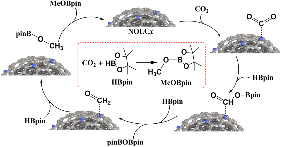 | ||
| Fig. 8 The proposed CO2 reduction mechanism catalyzed by NOLCx. | ||
4. Conclusion
In this study, metal-free nanocarbon catalysts for effectively catalyzing CO2 reduction were synthesized via N doping on the OLC surface, which was confirmed by HRTEM, EDX, XPS and Raman spectroscopy. NOLCx demonstrated the novel and excellent capacity of catalyzing CO2 hydroboration, where N-doping species and content play an important role. Pyridinic N and pyrrolic N might be the potential catalytic active sites, rather than graphitic N species. In situ IR was utilized to discover the catalytic mechanism by which chemisorbed CO2 would be transformed into the reaction intermediate OCH–O–Bpin with the help of N doping and HBpin. To the best of our knowledge, this work presents the first report on CO2 hydroboration catalyzed by a heterogeneous metal-free nanocarbon catalyst, thus not only expanding the catalytic application scenario of nanocarbon materials but also providing a deeper understanding of carbon surface chemistry.
Author contributions
Tao Du: writing – original draft, visualization, validation, software, investigation, and formal analysis. Peng Zhang: writing – original draft, visualization, and software. Guofeng Wang: investigation, formal analysis, data curation, and Conceptualization. Zhen Jiao: writing – original draft, visualization, and software. Jiancheng Zhou: supervision, resources, and formal analysis. Yuxiao Ding: writing – review & editing, writing – original draft, project administration, methodology, investigation, funding acquisition, formal analysis, data curation, and conceptualization.Data availability
The authors confirm that the data supporting the findings of this article are available within the main article and its ESI.†Conflicts of interest
There are no conflicts to declare.Acknowledgements
We acknowledge the funding support from State Key Laboratory of Low Carbon Catalysis and Carbon Dioxide Utilization, Lanzhou Institute of Chemical Physics, Chinese Academy of Science. Prof. Yuxiao Ding acknowledges the funding from the project supported by the National Natural Science Foundation of China (Grant No. 22202217), the funding from the project supported by the Joint Fund of Shandong Energy Institute and Enterprise (Grant No. SEI U202308), the funding from the Project supported by the Natural Science Foundation of Gansu Province, China (Grant No. 23ZDFA016) and the funding from the project supported by National Key Research and Development Program of China (Grant No. 2022YFA1504602).References
- M. Aresta, A. Dibenedetto and A. Angelini, Chem. Rev., 2014, 114, 1709–1742 CrossRef CAS PubMed.
- B. Grignard, S. Gennen, C. Jérôme, A. W. Kleij and C. Detrembleur, Chem. Soc. Rev., 2019, 48, 4466–4514 CAS.
- Z. K. Zhang, Z. Y. Yang, L. N. Liu, Y. R. Wang and S. Kawi, Adv. Energy Mater., 2023, 13, 2301852 CrossRef CAS.
- M. D. Garba, M. Usman, S. Khan, F. Shehzad, A. Galadima, M. F. Ehsan, A. S. Ghanem and M. Humayun, J. Environ. Chem. Eng., 2021, 9, 104756 CAS.
- W. Ji, J. Liu, C. Sha, Y.-C. Yong, Y. Jiang and Z. Fang, Green Carbon, 2024, 2, 322–336 Search PubMed.
- W. Wang, S. Wang, X. Ma and J. Gong, Chem. Soc. Rev., 2011, 40, 3703–3727 RSC.
- R.-P. Ye, J. Ding, W. Gong, M. D. Argyle, Q. Zhong, Y. Wang, C. K. Russell, Z. Xu, A. G. Russell, Q. Li, M. Fan and Y.-G. Yao, Nat. Commun., 2019, 10, 5698 CrossRef CAS.
- S.-T. Bai, G. De Smet, Y. Liao, R. Sun, C. Zhou, M. Beller, B. U. Maes and B. F. Sels, Chem. Soc. Rev., 2021, 50, 4259–4298 Search PubMed.
- J. Zhong, X. Yang, Z. Wu, B. Liang, Y. Huang and T. Zhang, Chem. Soc. Rev., 2020, 49, 1385–1413 Search PubMed.
- W. Wang, C. Zeng and N. Tsubaki, Green Carbon, 2023, 1, 133–145 CrossRef.
- Y. Zhang, T. Zhang and S. Das, Green Chem., 2020, 22, 1800–1820 RSC.
- R. A. Pramudita and K. Motokura, Green Chem., 2018, 20, 4834–4843 RSC.
- F. Ritter, T. P. Spaniol, I. Douair, L. Maron and J. Okuda, Angew. Chem., Int. Ed., 2020, 59, 23335–23342 CrossRef CAS PubMed.
- C. Chen, Q. Mo, Y. Huang and L. Zhang, ACS Catal., 2023, 13, 6837–6845 CrossRef CAS.
- A. Berkefeld, W. E. Piers and M. Parvez, J. Am. Chem. Soc., 2010, 132, 10660–10661 CrossRef CAS.
- S. Kostera, M. Peruzzini and L. Gonsalvi, Catalysts, 2021, 11(1), 58 CrossRef CAS.
- D. Mukherjee, H. Osseili, T. P. Spaniol and J. Okuda, J. Am. Chem. Soc., 2016, 138, 10790–10793 CrossRef CAS.
- S. Bontemps, Coord. Chem. Rev., 2016, 308, 117–130 CrossRef CAS.
- C. Erken, A. Kaithal, S. Sen, T. Weyhermuller, M. Holscher, C. Werle and W. Leitner, Nat. Commun., 2018, 9, 4521 Search PubMed.
- S. Kostera, S. Weber, I. Blaha, M. Peruzzini, K. Kirchner and L. Gonsalvi, ACS Catal., 2023, 13, 5236–5244 CAS.
- M. A. Courtemanche, M. A. Legare, L. Maron and F. G. Fontaine, J. Am. Chem. Soc., 2014, 136, 10708–10717 CAS.
- Y. Zhang, H. Zhang and K. Gao, Org. Lett., 2021, 23, 8282–8286 CAS.
- S. Zhao, H. Q. Liang, X. M. Hu, S. Li and K. Daasbjerg, Angew. Chem., Int. Ed., 2022, 61, e202204008 CrossRef CAS.
- S. J. Geier, C. M. Vogels, J. A. Melanson and S. A. Westcott, Chem. Soc. Rev., 2022, 51, 8877–8922 RSC.
- M. Szewczyk, M. Magre, V. Zubar and M. Rueping, ACS Catal., 2019, 9, 11634–11639 CrossRef CAS.
- M. Magre, M. Szewczyk and M. Rueping, Chem. Rev., 2022, 122, 8261–8312 CrossRef CAS PubMed.
- T. Du, P. Zhang, Z. Jiao, J. Zhou and Y. Ding, Chem. – Asian J., 2024, 19, e202400208 Search PubMed.
- C. M. Momming, E. Otten, G. Kehr, R. Frohlich, S. Grimme, D. W. Stephan and G. Erker, Angew. Chem., Int. Ed., 2009, 48, 6643–6646 Search PubMed.
- A. E. Ashley, A. L. Thompson and D. O'Hare, Angew. Chem., Int. Ed., 2009, 48, 9839–9843 CrossRef CAS PubMed.
- M. A. Courtemanche, M. A. Legare, L. Maron and F. G. Fontaine, J. Am. Chem. Soc., 2013, 135, 9326–9329 CAS.
- C. Das Neves Gomes, E. Blondiaux, P. Thuery and T. Cantat, Chem. – Eur. J., 2014, 20, 7098–7106 CAS.
- T. Wang and D. W. Stephan, Chem. Commun., 2014, 50, 7007–7010 RSC.
- J. Fan, J.-Q. Mah, M.-C. Yang, M.-D. Su and C.-W. So, J. Am. Chem. Soc., 2021, 143, 4993–5002 CrossRef PubMed.
- X. Liu and L. Dai, Nat. Rev. Mater., 2016, 1, 16064 CrossRef CAS.
- S. Liu, H. Yang, X. Huang, L. Liu, W. Cai, J. Gao, X. Li, T. Zhang, Y. Huang and B. Liu, Adv. Funct. Mater., 2018, 28, 1800499 CrossRef.
- J. J. Wu, R. M. Yadav, M. J. Liu, P. P. Sharma, C. S. Tiwary, L. L. Ma, X. L. Zou, X. D. Zhou, B. I. Yakobson, J. Lou and P. M. Ajayan, ACS Nano, 2015, 9, 5364–5371 CrossRef CAS PubMed.
- X. Hao, X. An, A. M. Patil, P. Wang, X. Ma, X. Du, X. Hao, A. Abudula and G. Guan, ACS Appl. Mater. Interfaces, 2021, 13, 3738–3747 CrossRef CAS PubMed.
- A. Samikannu, L. J. Konwar, P. Mäki-Arvela and J.-P. Mikkola, Appl. Catal., B, 2019, 241, 41–51 CrossRef CAS.
- Y. Ding, X. Sun, L. Zhang, S. Mao, Z. Xie, Z. W. Liu and D. S. Su, Angew. Chem., Int. Ed., 2015, 54, 231–235 CrossRef CAS.
- J. P. Paraknowitsch, J. Zhang, D. Su, A. Thomas and M. Antonietti, Adv. Mater., 2010, 22, 87–92 CrossRef CAS.
- Y. Lin, X. Sun, D. S. Su, G. Centi and S. Perathoner, Chem. Soc. Rev., 2018, 47, 8438–8473 RSC.
- M. Zeiger, N. Jäckel, V. N. Mochalin and V. Presser, J. Mater. Chem. A, 2016, 4, 3172–3196 RSC.
- Y. Ding, X. Huang, X. Yi, Y. Qiao, X. Sun, A. Zheng and D. S. Su, Angew. Chem., Int. Ed., 2018, 57, 13800–13804 CrossRef CAS PubMed.
- Y. Ding and D. S. Su, ChemSusChem, 2014, 7, 1542–1546 CrossRef CAS PubMed.
- M. Zhao, T. Li, L. Jia, H. Li, W. Yuan and C. M. Li, ChemSusChem, 2019, 12, 5041–5050 CrossRef CAS PubMed.
- X. Fan, M. Zhao, T. Li, L. Y. Zhang, M. Jing, W. Yuan and C. M. Li, Nanoscale, 2021, 13, 18332–18339 RSC.
- K. Ghosh, M. Kumar, T. Maruyama and Y. Ando, J. Mater. Chem., 2010, 20, 4128–4134 RSC.
- K. Chizari, A. Vena, L. Laurentius and U. Sundararaj, Carbon, 2014, 68, 369–379 CAS.
- L.-S. Zhang, X.-Q. Liang, W.-G. Song and Z.-Y. Wu, Phys. Chem. Chem. Phys., 2010, 12, 12055–12059 RSC.
- P. Zhang, J. Fan, Y. Wang, Y. Dang, S. Heumann and Y. Ding, Carbon, 2024, 222, 118998 CrossRef CAS.
- Y. Lin, Z. Liu, L. Yu, G. R. Zhang, H. Tan, K. H. Wu, F. Song, A. K. Mechler, P. P. M. Schleker, Q. Lu, B. Zhang and S. Heumann, Angew. Chem., Int. Ed., 2021, 60, 3299–3306 CAS.
- L. Yu, L. Tang, W. Guo, C. Li, D. Shin, Z. Liu and Y. Lin, Matter, 2022, 5, 1909–1923 CrossRef CAS.
- L. Chen, R. Liu and Q. Yan, Angew. Chem., Int. Ed., 2018, 57, 9336–9340 CrossRef CAS.
- B. R. Van Ausdall, J. L. Glass, K. M. Wiggins, A. M. Aarif and J. Louie, J. Org. Chem., 2009, 74, 7935–7942 CrossRef CAS PubMed.
- L. F. B. Wilm, T. Eder, C. Mück-Lichtenfeld, P. Mehlmann, M. Wünsche, F. Buß and F. Dielmann, Green Chem., 2019, 21, 640–648 RSC.
Footnote |
| † Electronic supplementary information (ESI) available. See DOI: https://doi.org/10.1039/d4nr04225e |
| This journal is © The Royal Society of Chemistry 2025 |