
 Open Access Article
 This Open Access Article is licensed under a Creative Commons Attribution-Non Commercial 3.0 Unported Licence
Nanoscale insights into vibration-induced heterogeneous ice nucleation†
Pengxu
Chen
 *,
Rohit
Pillai
and
Saikat
Datta‡
*,
Rohit
Pillai
and
Saikat
Datta‡
Institute for Multiscale Thermofluids, School of Engineering, University of Edinburgh, King's Buildings, EH9 3FB, Edinburgh, UK. E-mail: pengxu.chen@ed.ac.uk
First published on 13th May 2025
Abstract
Accelerating ice nucleation in confined liquids is desirable in applications like food freezing, cryopreservation, and ice casting, but current techniques have their limitations. The use of high-frequency acoustic waves (AW) is a promising alternative but remains poorly-understood. We employ molecular dynamics simulations to investigate AW-induced ice nucleation within confined nanopores. By systematically varying vibrational amplitude and frequency, we identify five distinct nucleation regimes, forming a comprehensive regime map that links these parameters to nucleation outcomes. Our simulations reveal that ice nucleation is preceded by formation of ice-like clusters, and is strongly influenced by negative pressure induced by surface vibrations. A strain-based criterion is introduced to generalize the findings to larger lengthscales. This enables us to propose a universal framework for controlling ice formation via surface vibrations in industrial applications.
1. Introduction
Ice nucleation starts when tiny (pre-critical) ice crystals form from the vapour or liquid phase. It has been known for over 75 years1 that this nucleation process preferentially occurs heterogeneously, i.e. on surfaces. This fundamental phase transition is crucial in many natural phenomena, such as snow and ice formation,2 which directly impact climate patterns. Controlling ice formation is also essential in various engineering applications, including food freezing,3 cryopreservation,4 and ice casting.5 These practical needs have sparked interest in manipulating ice nucleation rates using external stimuli such as electric fields,6 magnetic fields,7 and acoustic waves.8 However, generating strong electric and magnetic fields often requires substantial energy inputs, which presents practical limitations. In contrast, acoustic waves (AW) emerge as a promising alternative due to their lower energy requirements and effectiveness.AW such as ultrasound has been shown to induce and accelerate ice nucleation and subsequent crystal growth.9 In food engineering, AW has been applied to enhance the freezing efficiency of foods.10 Experimental AW parameters, such as ultrasonic power and duration of treatment, significantly influence nucleation rate by reducing the freezing time,11 while low frequencies and high power have been shown to induce ice nucleation.12–14 The role of fluid flow rates, temperature, and probe position have also received attention.15 However, while extensive experimental literature exists on optimizing AW parameters for various materials,16 relatively limited attention has been devoted to clarifying the fundamental physical mechanisms underlying AW-induced nucleation. Recent advances mean that experimental AW spans frequencies from a few megahertz all the way to a few gigahertz, and amplitudes ranging from angstroms to a few nanometres.17–21 Given these extremely rapid timescales and extremely small lengthscales, and the fact that nucleation starts at the nanoscale, AW-induced nucleation mechanisms remain challenging to investigate. Consequently, how and why nucleation occurs remains heavily debated.
Several mechanisms have been proposed to explain vibration-induced nucleation, with most centering on cavitation effects triggered by acoustic excitation.22 Among the leading theories are microstreaming23,24 and pressure-driven nucleation.25 Microstreaming23 involves strong localized fluid flows generated by oscillating cavitation bubbles. These flows, with velocities exceeding those of conventional acoustic streaming (∼0.1 m s−1), significantly enhance local mass and heat transfer, potentially influencing nucleation processes. Nomura et al.24 demonstrated that cavitation bubble streaming is distinct from traditional acoustic streaming, featuring rapid flows directly driven by bubble motion, which can increase the rate of heat transfer.
In contrast, Hickling's model25 posits a more direct mechanism: the violent collapse of cavitation bubbles causes rapid, adiabatic compression of the surrounding liquid, creating localized zones of extreme pressure. In water, this can lead to conditions where the liquid becomes supercooled relative to its pressure-dependent freezing point, thereby triggering nucleation via homogeneous pathways. As one of the older and widely cited cavitation-based models, Hickling's theory has been reinforced by subsequent reviews and experimental studies highlighting the capacity of collapsing bubbles to generate the necessary thermodynamic extremes for spontaneous ice formation.26,27 However, multiple experimental studies have observed a noticeable delay between bubble collapse and nucleation onset,28,29 suggesting the involvement of intermediate steps or additional factors that are not taken into account by purely pressure-driven models. Note that Navier-Stokes based numerical models are not useful here as they typically presuppose cavitation and then investigate how the formed bubbles influence nucleation.30,31 Therefore, whether surface vibrations alone (independent of cavitation) may influence nucleation behavior and how vibrations and cavitation interact during nucleation processes remain poorly understood. This motivates our first research question: What are the precise underlying mechanisms by which acoustic waves induce cavitation and ice nucleation?
While traditional applications of AW-induced nucleation have focused on macroscale systems, recent developments have extended interest to micro-/nano-scale environments, where supercooled water is confined within 10–100 nm nanopores (see Fig. 1A(a–f)), making them even more challenging to probe experimentally. As an alternative to both experimental techniques and continuum-scale Navier–Stokes modeling, molecular dynamics (MD) simulations offer a powerful tool to directly observe ice nucleation events as they occur from the water phase itself.32–34 However, because ice nucleation is a rare event that typically unfolds over microsecond timescales or longer, MD simulations face inherent limitations; as they are computationally intensive, simulating long timescales restricts the feasible system size. As a result, MD can only capture a small spatial and temporal window of the full nucleation process, complicating efforts to extrapolate findings to larger-scale or more real-world systems. Consequently, any mechanistic insight derived from MD at the molecular scale must be validated for its applicability at larger scales in order to address the first research question posed earlier. This leads to a second research question: Can the effects of vibration on ice nucleation observed in MD simulations be generalized; i.e., are they independent of system size?
 | ||
| Fig. 1 (A) Examples of scenarios involving confined water, including (a) ice casting processes;35 (b) food freezing;36 (c) freezing soil;37 (d) plant freezing;38 (e) wastewater treatment;39 and (f) microfluidic channels.40 (B) Illustration of ice nucleation when surface vibration is applied; ice nucleation and growth in the confined channel during 100 ns. | ||
In this study, we aim to address these two open questions by: (a) performing systematic MD simulations across a range of AW frequencies and amplitudes, separating the effects of surface vibration, cavitation effects, and ice nucleation; and (b) running a second set of MD simulations, this time varying the system dimensions across a range of sizes, to demonstrate that the insights gained in part (a) are applicable to larger scales.
2. Methods
All molecular dynamics (MD) simulations were performed using the LAMMPS package.41 To simulate AW in supercooled water, confined in a nano-pore, we developed a “sandwich” setup (see Fig. 1B) where a water layer is confined between two surfaces, each with a size of 86.24 Å × 86.24 Å × 16.7 Å. A vibrational boundary condition was assigned to one of the surfaces while keeping the other one fixed, to mimic the perturbation caused by AW. The displacement of the vibrated surface with time can be given byx(t) = A![[thin space (1/6-em)]](https://www.rsc.org/images/entities/char_2009.gif) sin(2πft), sin(2πft), | (1) |
087 water molecules. The surfaces are constructed using an FCC crystal with a lattice constant of 3.92 Å, oriented along the (100) crystallographic plane. Note that our objective is not to investigate ice nucleation on specific surface materials but to capture the general behaviours of supercooled water on idealized structured surfaces, and hence we use the FCC surface to represent a generic surface material.43 The interactions of mW water-surface and surface-surface are described by a truncated 12/6 Lennard-Jones potential, | (2) |
 | (3) |
 | (4) |
 | (5) |
The confined water system was first equilibrated at 290 K for 10 ns. The water was then supercooled from 290 K to 220 K at a rate of 1 K ns−1 (ref. 44) (see ESI section S2† for details). During this cooling process, the bottom surface was fixed, while the upper surface was allowed to move vertically to accommodate volume changes due to the thermal contraction of the water layer. After cooling, the thermostat was removed from the water molecules and applied only to the top and bottom surfaces. These surfaces were maintained at 220 K for 20 ns to allow the system to relax. During this period, configurations were saved every 2 ns to produce statistically independent trajectories. These trajectories served as starting points for the subsequent simulation phase, where surface vibration is imparted. Non-equilibrium MD simulations were then performed by applying harmonic vibrational motion to the bottom surface while keeping the top surface stationary. Both surfaces were thermostated at 220 K to maintain the temperature of the confined water indirectly through surface–fluid interactions, minimizing perturbations to the water dynamics and allowing for natural heat exchange processes. The CHILL+ algorithm was employed to detect molecules in the ice phase during the simulations.45
Each simulation was terminated either 10 ns after a significant drop was observed in the potential energy of water (greater than 0.3 kcal per mol per water molecule), indicating ice formation, or when the simulation time exceeded 100 ns. This potential energy threshold 0.3 kcal mol−1 is based on previous studies where a similar drop was shown to correlate with the onset of ice nucleation.46 To ensure statistical reliability, each set of simulation conditions (i.e. each unique combination of frequency and amplitude) was validated by performing at least two production runs starting from different equilibrium configurations, accounting for the variability in supercooled water behaviour.
3. Results and discussion
3.1 Regime map
Experimental AW devices can be categorised as moderately-high frequency devices (up to 300 MHz (ref. 20)) and ultrahigh frequency (300 MHz–3 GHz (ref. 19)). The amplitude of surface vibrations can also similarly vary from a few angstrom to a few nanometres.17,19–21 For this work, we conducted a broad parametric study in the range of experimental capabilities by varying vibrational frequencies from 25 MHz to 700 MHz, and amplitudes ranging from 8 Å to 30 Å. In this parametric study, we identified five distinct regimes, summarised in a regime map (Fig. 2). In all cases where nucleation was observed, precursor ice nuclei comprising a few water molecules in the ice phase first formed on the surface. Once sufficient molecules in the ice phase form and accumulate, ice nucleation occurs, followed by formation of an ice front that rapidly grows and envelops the entire domain (see ESI video†). The nucleation was always heterogeneous in origin and the ice front formed at either the bottom or top surface. The boundaries between these regimes were manually delineated, and the zones were separated using different background colours for clarity. Simulation of static surfaces without any vibrations was performed as a control. All control simulations showed no nucleation within 100 ns, indicating that nucleation does not occur in the absence of AW (within the timescales studied). | ||
| Fig. 2 Regime map illustrating the behaviour of supercooled water subjected to surface vibrations across different frequencies and amplitudes. The map characterizes five distinct zones: the red zone denotes complete nucleation where ice forms without cavitation; the orange zone indicates partial nucleation with a decreasing likelihood of ice formation; the yellow zone represents conditions where no nucleation occurs; the dark blue zone shows nucleation accompanied by cavitation; and the light blue zone highlights conditions where only cavitation occurs without inducing ice nucleation. The snapshot of the simulation domain, representing different regimes, is shown in the insets. | ||
We will describe each regime in this section, beginning with those below a critical threshold of amplitude (22 Å), for reasons that will become apparent later. Going from left to right, we start with the one highlighted in red, corresponding to f < 200 MHz and 12 Å < A < 20 Å. This regime represents the most favourable conditions for ice nucleation, and we denote this as complete nucleation regime. All production simulations in this regime showed ice nucleation within the simulation duration. Next, the orange regime around it corresponds to a lower likelihood of ice nucleation. In this regime, ice nucleation is observed within 100 ns in not all but at least one of the production simulations, and we denote this regime as partial nucleation. The yellow regime next to it corresponds to regime where no nucleation was observed in any of the production runs, the same as the static surfaces where there is no vibration. This means the surface vibrations in this regime have negligible influence on ice nucleation. The three regimes mentioned above present a transition from the significant enhancement of ice nucleation (red regime) to the least affected regime (yellow regime). This was verified by calculating the nucleation rates of one case in each of these three regimes (see ESI section S3† for details).
Moving onto the regimes above the previously mentioned critical threshold of 22 Å, cavitation is observed. This is because when the amplitude exceeds this critical threshold, a large deformation/strain is induced within the water when the lower surface moves away, thus triggering cavitation.47 The two blue regimes, both correspond to cavitation, but there are differences between them. Specifically, the dark blue regime corresponding to f < 150 MHz and 22 Å < A < 29 Å is characterised by the occurrence of nucleation alongside cavitation. This typically occurs when the timescale of nucleation is similar to that of cavitation onset. In this regime, at least one instance of ice nucleation was observed out of all production runs, indicating that nucleation is possible. Beyond the dark blue regime, the light blue regime indicates that only cavitation was observed without any instances of nucleation, indicating that nucleation was improbable. This is likely because the timescale of cavitation is shorter than that of nucleation, i.e. once cavitation occurs, nucleation is no longer probable for reasons that will become clearer later.
While the dark blue regime depicts scenarios similar to those in previous experimental studies—i.e. ice nucleation with cavitation—the observed ice nucleation in the absence of cavitation challenges long-standing theories25 that emphasize the critical role of cavitation bubbles in facilitating ice nucleation. With these different regimes identified, the following sections will delve into each regime to investigate the underlying mechanisms that produce the observations described thus far.
3.2 Ice phase molecules in supercooled water
As nucleation is a stochastic event, molecules in the ice phase continuously form and dissipate in supercooled water. According to Classical Nucleation Theory (CNT),48 ice nucleation occurs only when these molecules in the ice phase form an ice nucleus that is larger than a specified threshold, referred to as a critical nucleus. An increased number of molecules in the ice phase promotes the formation of larger ice-like clusters, which enhances the probability of overcoming the critical nucleus size associated with ice nucleation. We investigate how surface vibrations affect the generation and dynamics of these molecules in the ice phase that can potentially serve as nuclei for ice nucleation and growth (which may or may not happen at a later point in the simulation). Note that the critical nucleus size is dependent on temperature; existing molecular dynamics (MD) simulations have indicated that, at 220 K, the critical nucleus size for homogeneous nucleation using the mW water model ranges from 85 to 265 molecules.49–51 As the number of molecules required to form a critical nucleus is lower for heterogeneous nucleation for the same radius of curvature (the nucleus takes on a spherical cap shape in this case and not a spherical shape as is the case for homogeneous nucleation52), this critical nucleus size range is an approximation. In any case, in the present study, the critical nucleus size is not calculated due to the non-equilibrium conditions resulting from surface vibrations. Instead, we aim to study how molecules in the ice phase form clusters that grow or dissipate in time and link the behaviour of these clusters to nucleation.We plot the count of molecules in the ice phase (comprising both cubic ice and hexagonal ice structures) for a typical case using CHILL+ (ref. 45) in Fig. 3A. Note that CHILL+ identifies water molecules in the ice phase by analyzing the local hydrogen-bonding geometry around each molecule, comparing it to the known structural patterns of ice. It classifies water molecules as belonging to the ice phase if their bonding angles and neighbor arrangements closely match those in crystalline ice structures like hexagonal ice or cubic ice. Our results using CHILL+ show that the number of molecules in the ice phase oscillates with the applied vibrations. Note that this is observed even in cases where nucleation does not eventually result, i.e. the mere presence of these precursor ice phase molecules does not necessarily imply that nucleation will result. We observe that when the lower surface moves away from the confined water layer, the number of molecules in the ice phase increases, whereas this number decreases when the surface moves towards the water (Fig. 3B). This fluctuation of molecules in the ice phase with surface vibration will be discussed later.
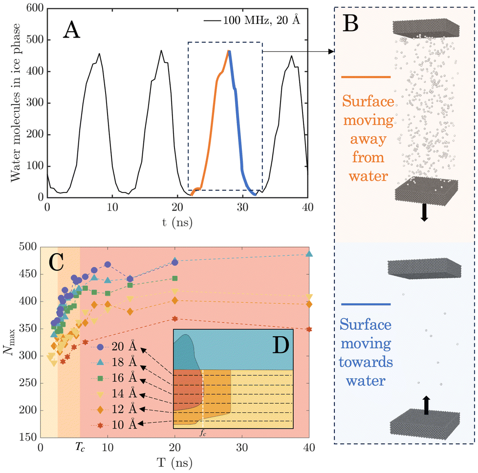 | ||
| Fig. 3 (A) Temporal variation of the number of molecules in the ice phase, in response to surface vibrations. (B) Snapshots of the simulation domain showing oscillation of the molecules in the ice phase. The number of molecules in the ice phase increases when the surface moves away from the water layer and decreases when the surface compresses it. The maximum number of molecules in the ice phase, Nmax, is determined by averaging the peak values over time. (C) Variation of Nmax as a function of the vibrational period T (1/f) for each amplitude. The arrows in the regime map (D) indicate transitions across regimes yellow-orange-red, corresponding to the regimes in (C) which is shaded by the same colours. | ||
By averaging the peak values of molecules in the ice phase over time, we obtain a new parameter that we call maximum number of molecules in the ice phase, Nmax. Since cavitation causes sudden changes in the water's properties, we only sampled the non-cavitation regimes (amplitudes between 10 Å and 20 Å) for analysis. Nmax at each sampled case was plotted against period T (reciprocal of f), as shown in Fig. 3C. We matched the background of Fig. 3C with the same colour palette (red, orange, and yellow) as the regime map (Fig. 2, shown as inset in Fig. 3D) to show the respective regimes and boundaries between them. Fig. 3C shows that the magnitudes of Nmax vary with T for different amplitudes, shown as dashed lines of different colours. Higher-amplitude vibrations can generate a larger Nmax. This variation is lower for small values of T where the lines appear bunched up, but becomes more significant with a longer period, i.e. as you go from left to right in Fig. 3C. Irrespective of amplitude, Nmax increases with T for the left-most two regions (coloured yellow and orange, respectively), followed by reaching a constant value as T increases beyond that point. Note that once a constant value of Nmax is reached, the number of molecules in the ice phase is therefore independent of vibration parameters. The critical period Tc beyond which Nmax no longer increases is around the orange-to-red boundary line (Tc ≈ 6.67 ns). This Tc corresponds well with the transition frequency fc at the red-to-orange boundary in the regime map (fc ≈ 150 MHz). Thus, no variation in Nmax is observed either when T > Tc or when f < fc.
We show in the ESI section S4† that this consistent threshold in Tc (or fc) originates from the relaxation time scale associated with the water model. Once the vibration frequency/time-period is high/low enough to prevent the equilibration of water molecules, which is always the case when T < Tc, the perturbation occurs too rapidly for the liquid to recover its metastable structure between oscillation cycles. As a result, the molecular rearrangements needed for ice nucleation are suppressed. On the other hand as T increases beyond Tc, Nmax is shown to reach a stable maximum value and no longer increase. This saturated Nmax ensures that sufficient molecules in the ice phase are present to facilitate some of them to form larger clusters, exceed the critical nucleus threshold, and result in ice nucleation and growth. Note that this is identical to decreasing vibration frequency until fc is reached, at which point the regime of complete ice nucleation is reached in Fig. 2.
3.3 Ice origin on surfaces
A larger Nmax indicates an increase in the number of ice phase molecules in water, which reaches a critical value once a threshold frequency is reached. However, it is unclear just from using Nmax as to how these molecules are arranged: Do they form pre-critical clusters as would be predicted by CNT? If so, how large are these clusters? To answer these questions, we investigate the history of ice-phase molecule cluster formation before the onset of ice nucleation. An ice-phase cluster is an aggregation of molecules in the ice phase within a cutoff distance of 3.2 Å.46 A threshold of 25 molecules in the ice phase was used to identify the large clusters which were then analysed further (see ESI section S5† for detailed definitions and calculations). Since ice only nucleates heterogeneously in our simulations, we tracked the spatiotemporal trajectories of ice-like clusters with a distance of 10 Å above the surface. For cases where no nucleation was observed, we tracked the spatiotemporal distribution of clusters for the entire simulation time (100 ns), whereas for the cases where complete ice nucleation occurs before the 100 ns simulation duration, we performed this analysis only until ice nucleation occurred.Fig. 4A shows the cluster distribution at sample points in each of the regimes from the regime map diagram at three different amplitudes (10 Å, 18 Å, and 24 Å) with coloured lines (green, blue, and red respectively, presented at the top-left). The square plots (from 4(i) to 4(viii)) represent the spatiotemporal distribution of surface ice clusters (where viewed from the top) in different regimes. The size of each circle is proportional to the number of molecules in an ice-phase cluster. The colour indicates the time when the ice-like cluster appeared, varying from blue (start of simulation) to yellow (end of simulation). We can see that 4(iii) has the most clusters of ice-phase molecules, while 4(i), 4(iv), and 4(vi) have fewer large ice clusters on the surfaces, indicating a relatively lower likelihood of nucleation occurrence. Finally, 4(ii), 4(v), 4(vii), and 4(viii) show even fewer large ice clusters on the surface. In particular, no large cluster is observed for 4(ii). All these results are consistent with the regime map as expected, with greater clusters in the complete nucleation regimes to proportionally fewer in the partial and no nucleation regimes, respectively. To quantify the ice clusters on the surfaces, we then calculated the probability density of cluster size at different amplitudes (Fig. 4B). This will be further discussed in the following section.
 | ||
| Fig. 4 (A) Graphs with coloured circles ((i)–(viii)) indicate the spatiotemporal distribution of ice-like clusters on the surface over the simulation time at locations at different regimes. The size of each circle represents the number of ice-like clusters and the colour indicates the time; only clusters containing more than 25 molecules in the ice phase are tracked. For the static surface case, no clusters are detected. (B) Histograms demonstrating the probability distribution of cluster sizes at each case in (A). | ||
3.4 Role of negative pressure
As the nucleation probability can be linked to the presence and quantity of pre-critical clusters of molecules in the ice phase, we next study how these clusters form. We hypothesise that the pressure field produced by surface vibration is the primary reason for the enhancement of the probability of nucleation. This likely occurs because any liquid subjected to pressure variations undergoes a nucleation point shift, as per the Clausius–Clapeyron equation.53 Therefore, we measured the local interaction force (Floc) perpendicular to the water–surface interface, and used it to estimate the local pressure at the interface by Ploc = Floc/Asur, where Asur is the area of the surface. Fig. 5A shows the variation of Ploc for a representative case (50 MHz, 14 Å), and it can be seen that it fluctuates in an oscillatory manner similar to the surface itself. Ploc thus increases when the lower (vibrating) surface moves upward, compressing the confined water. As the lower surface moves downward and passes the initial equilibrium position, the water is stretched and Ploc becomes negative. The bulk pressure of all water molecules during vibration along the direction of surface motion was also measured and a similar oscillatory trend is observed (see ESI section S6†). | ||
| Fig. 5 (A) Oscillations of the local pressure at the water–surface interface induced by surface vibrations. The pressure data are fitted using a third-order Fourier equation, and Pmag is determined as the absolute minimum value. (B) Variation of the maximum number of molecules in the ice phase, Nmax, as a function of vibrational period T. (C) Three-dimensional plot of the Nmaxvs. frequency and amplitude converted from (B). (D) Variation of Pmag with frequency and amplitude. | ||
The consensus in the literature on pressure-controlled AW-induced ice nucleation (as originally postulated by Hickling25) is that the positive pressure occurring during the collapse of transient cavitation increases the equilibrium nucleation temperature of water, thereby enhancing the probability of ice nucleation inception at a given temperature. However, as seen in Fig. 3B and confirmed in the trajectories of surface vibration simulations, all instances of ice nucleation in the current study occur only when the vibrating surface is moving away from the water layer, i.e. when the pressure is negative. This observation aligns with previous studies that have revealed that negative pressure within supercooled water provides favorable conditions for inducing ice nucleation.54–61 This negative-pressure induced nucleation likely results from the confinement and the presence of a solid surface in our case. We identified the magnitude of the maximum negative pressure Pmag as a characteristic parameter for ice nucleation. Pmag was estimated by fitting the Ploc data with a third-order Fourier model,62 and recording the magnitude of the absolute minimum value of the fitted function. This was done for a same range of amplitudes where no cavitation is observed (between 10 Å and 20 Å) for all frequencies.
While Fig. 2 provides an overview of the probability of ice nucleation across combinations of vibration parameters (i.e., amplitude and frequency), it does not provide physical insight into underlying mechanisms. We therefore analyse the variation of Pmag alongside Nmax for the combination of vibrational amplitudes and frequencies studied in Fig. 2. To obtain a comparison of Pmag and Nmax with the acoustic parameters within the regime of interest (i.e., amplitudes between 10 Å and 20 Å), Nmax is first replotted as a function of frequency rather than period (the lines in Fig. 5B are rendered as slices in Fig. 5C). Next, a three-dimensional plot of Nmax is used to dis-aggregate the role of amplitude and frequency (Fig. 5C). Note that, since the plot involves both the amplitude and frequency axes, it also enables a direct comparison of Nmax for all the regimes in the regime map (Fig. 2). The Pmag in each case of (Fig. 5C) was calculated and included in Fig. 5D. Two important observations can be made about Fig. 5D (highlighted using a blue plane): first, at a given amplitude, Pmag does not change as frequency is varied, and therefore the role of frequency in the ice nucleation process is independent of Pmag. Second, higher amplitudes induce higher Pmag, and a linear correlation can be found between applied vibration amplitude and calculated Pmag. As higher Pmag is more favourable for ice nucleation, this change in Pmag explains the transition from non-nucleation to nucleation regimes as amplitude is increased in Fig. 2 (for a fixed frequency). For instance, at 150 MHz, there is a transition across the yellow, orange, to the red zone in Fig. 2 (no nucleation, partial nucleation, to complete nucleation regime) as amplitude is increased from 8 Å to 22 Å.
The thermodynamic state variables that characterise the system are its temperature and pressure. As the temperature is regulated by the thermostat on the surfaces, the system's thermodynamic state only depends on the pressure. While a small fluctuation in temperature around the thermostatted surface temperature is observed during surface vibrations, we show in section S7 of the ESI† that this can be attributed to the variation in the number of ice-phase molecules during the vibrations. Therefore, the constant Pmag observed at a given amplitude means that the thermodynamic state of the system (when the bottom surface is at the lowest position) is unchanged when frequency is varied. As the nucleation barrier is determined by thermodynamic state, the energy required for a given nucleation cluster to develop is also not influenced by varying frequency. As a result, we can directly compare cases in Fig. 4A as long as the amplitude is the same. Note that this is not true when amplitude is varied because the thermodynamic state varies, and therefore cases that seem superficially similar may have different energy barriers to nucleation. We observe that along each horizontal line (constant amplitude) of the regime map in Fig. 4A, a reduction is shown in the formation of large ice clusters with increasing frequency. This phenomenon is more obvious for higher amplitudes at the top two rows (locations (i)–(v)) in Fig. 4A. To quantify the ice clusters that appeared on the surfaces, the probability densities of ice cluster sizes (Fig. 4B) are calculated along different amplitudes. The results are consistent with the spatiotemporal distribution in Fig. 4A, where location (iii) has the most clusters larger than 25 molecules (coloured in red). Regions away from location (iii) have fewer large clusters. At each amplitude, the probability density of larger ice clusters (>25) is larger when the frequency is low (locations (i), (iii), and (vi)). However, as the frequency increases, the probability density tends to show a smaller cluster size distribution.
While nucleation is triggered by negative pressure in all cases, our key takeaways are that: (a) as the vibration amplitude increases, Pmag increases linearly until the threshold for nucleation is reached, and (b) as the vibration frequency increases, the nucleation process is additionally controlled by the relaxation time of the water molecules; once fc is reached, nucleation is less likely to occur despite Pmag being sufficiently large. These two facts taken together explain the regimes observed in Fig. 2. Note that cavitation occurs when the tensile stress within the fluid exceeds the cohesive forces between molecules, resulting in the formation of vapor cavities or bubbles.63 Once cavitation initiates, the generated vapor cavity effectively acts as a pressure release mechanism, rapidly reducing the negative pressure to a more stable, near-zero value, despite the amplitude continuing to increase (see ESI section S8† for details). This pressure equalization occurs because the vapor cavity or bubble formed during cavitation acts as a compressible region, absorbing the additional strain energy instead of producing further reduction in liquid pressure. This means that once cavitation occurs, nucleation is no longer possible in our setup. The regime in which cavitation and nucleation are observed simultaneously only exists because nucleation occurs before cavitation equalizes the pressure.
Note that all these results were obtained from simulations with a confined water layer of 238 Å thick. However, as we see that the underlying mechanisms are quite general, the results reported here ought to be generalisable to larger nanopores, or even bulk systems. In the next section, we investigate the scale sensitivity of the results by increasing the domain size, specifically the thickness of the water layer, to study the behaviour of supercooled water at larger scales.
3.5 Non-dimensional scaling
We conducted simulations with four additional setups, each with different water thicknesses after equilibration at 290 K for 10 ns: 100 Å, 352 Å, 466 Å, and 691 Å (confinement effects were shown to be negligible, see ESI section S9†). Surface vibrations were applied to these systems while keeping the vibrational frequency fixed at 25 MHz. This frequency was identified as most likely to induce ice nucleation from the regime map as it includes most nucleation-intense regimes. Given that we have shown that vibration-induced nucleation depends on Pmag, we characterised our results using the applied strain ε, given by | (6) |
Fig. 6A shows regime distributions with different ε and hw. Importantly, the boundary between the ice nucleation and no ice nucleation regimes is horizontal along hw. This boundary corresponds to a critical value ε ≈ 0.04, as highlighted in Fig. 6A. The horizontal boundary indicates that the occurrence of ice nucleation is not dependent on hw but ε; once ε reaches the critical threshold of 0.04, ice nucleation will be triggered, regardless of hw. Note that there is a similar critical threshold that separates nucleation from the cavitation regimes, corresponding to ε ≈ 0.09. This finding reveals that all the previous results we obtained from hw = 238 Å also hold for the larger nanopores.
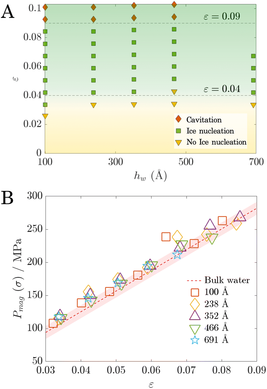 | ||
| Fig. 6 (A) Regime map illustrating the behaviour of supercooled water subjected to surface vibrations at different water thicknesses. All simulations were conducted at a frequency of 25 MHz. A horizontal boundary separating the nucleation and no-nucleation regimes is observed. (B) Variation of the Pmag as a function of strain ε for different water thicknesses hw. The volumetric stress–strain relationship of supercooled water at 220 K was plotted with the red band indicating the standard error. | ||
We also plot the corresponding Pmag values for all cases shown in Fig. 6A. The uniform distribution of Pmag at different hw (Fig. 6B) confirms that Pmag is not influenced by the water thickness hw as expected. It increases linearly with ε independently of system size. These results, consistent with that in Fig. 6A, confirm the scale-independent phenomenon of vibration-induced enhancement in ice-nucleation. Finally, we also ran a separate simulation on the supercooled bulk water at 220 K (the same temperature as the vibration simulations) to examine the water model's mechanical properties (see ESI section S10†). The results show that the distribution of Pmag in Fig. 6B aligns well with the volumetric stress–strain (σ–ε) relationship of the supercooled water as expected. The vibration-induced Pmag and the resulting volumetric stress σ thus follow the exactly same trend. Therefore we can conclude that it is the intrinsic properties of water—and not the geometric constraints of our system—that determine the negative pressure Pmag required to trigger ice nucleation.
Note that this study uses the mW water model,42 which does not properly capture the empirically-established density anomaly of water. Recently, a modified version of the mW model64 has been developed, which has been accurately shown to capture density/pressure effects for homogeneous nucleation.65 To ensure that the results presented in this work are not model-specific, we re-ran a subset of our simulations using this modified ML-mW model, and accurately reproduced the regimes detailed in this work (see ESI section S11† for details). These additional results support the robustness of our main conclusions and demonstrate that the mechanistic interpretation of AW-induced nucleation is not sensitive to the specific water model used, provided that the model reasonably captures the essential physics of tetrahedral coordination and negative pressure effects.
The ability to scale our (model-independent) findings to larger domains has significant implications for practical applications. We establish that once a suitable vibrational frequency has been identified, ice nucleation can be predictably triggered if the vibrational amplitude is adjusted so as to produce an applied strain within 0.04 < ε < 0.09. This provides a scalable strain-based criterion that can be used to inform larger-scale device designs.
4. Conclusions
This study investigates the mechanisms of acoustic wave (AW)-induced ice nucleation in confined supercooled water through molecular dynamics simulations, uncovering key parameters that govern nucleation behavior. By mapping the relationship between vibrational frequency, amplitude, and nucleation outcomes, we identified five distinct regimes that characterize ice formation and cavitation. Our findings highlight the critical role of negative pressure induced by surface vibrations in facilitating ice nucleation. Oscillations in the number of molecules in the ice phase, driven by the vibration of confining surfaces, were linked to the formation of pre-critical ice clusters that govern nucleation dynamics. Once sufficient pre-critical clusters form, nucleation probability is enhanced, and freezing eventually occurs. A major contribution of this work is the introduction of a dimensionless strain-based parameter which allows the results to be generalized across different system sizes.Here we employed atomically smooth surfaces with idealized LJ interactions to isolate the fundamental mechanisms of AW-induced ice nucleation. There are a few promising lines of possible future work. First, the influence of surface roughness and chemical heterogeneity for more realistic surfaces could be considered, which can introduce preferential nucleation sites, reducing the energy barrier for nucleation. Second, the role of electrostatic interactions which is neglected here could play a significant role in modifying interfacial water structure and energetics; this is particularly true for polar surfaces or in the presence of surface charges, both of which influence nucleation. Finally, experimental validation of the strain-based criterion proposed here would be instructive. This parameter ensures the scalability of nanoscale observations to macroscopic systems, making it possible to design AW-induced nucleation strategies for industrial applications, such as food freezing, cryopreservation, and wastewater treatment, with improved energy efficiency and control.
Author contributions
Pengxu Chen: data curation, formal analysis, investigation, methodology, software, validation, visualization, writing – original draft; Rohit Pillai: conceptualisation, funding acquisition, methodology, project administration, resources, supervision, validation, writing – review & editing; Saikat Datta: conceptualisation, funding acquisition, investigation, methodology, resources, supervision, validation, writing – review & editing.Data availability
The data files and scripts for a selected representative case that support the findings of this study are available at https://doi.org/10.7488/ds/7941. Details of the new LAMMPS fix validation, simulation temperature determination, nucleation rate calculation, relaxation time estimation, cluster analysis, bulk water pressure measurements, temperature fluctuation analysis, explanation of the impact of cavitation, confinement effect analysis, calculation of the bulk modulus of water, and analysis of the effect of the water model on the regime map can be found in the ESI.†Conflicts of interest
There are no conflicts to declare.Acknowledgements
The authors thank anonymous reviewers for improving this manuscript. S. D. acknowledges the support of the Leverhulme Trust through the award of an Early Career Fellowship ECF-2021-383. All molecular simulations were conducted on CIRRUS, a Tier-2 UK supercomputer, funded by an Access to HPC call.References
- N. E. Dorsey, Trans. Am. Philos. Soc., 1948, 38, 247–328 CrossRef CAS
.
- D. A. Knopf and P. A. Alpert, Nat. Rev. Phys., 2023, 5, 203–217 CrossRef CAS
- G. Jia, Y. Chen, A. Sun and V. Orlien, Compr. Rev. Food Sci. Food Saf., 2022, 21, 2433–2454 CrossRef CAS PubMed
- K. A. Murray and M. I. Gibson, Nat. Rev. Chem., 2022, 6, 579–593 CrossRef CAS PubMed
- U. G. K. Wegst, P. H. Kamm, K. Yin and F. García-Moreno, Nat. Rev. Methods Primers, 2024, 4, 1–23 CrossRef
- J.-M. Löwe, V. Hinrichsen, M. Schremb and C. Tropea, Phys. Rev. E, 2021, 103, 012801 CrossRef PubMed
- A. Kobayashi, M. Horikawa, J. L. Kirschvink and H. N. Golash, Proc. Natl. Acad. Sci. U. S. A., 2018, 115, 5383–5388 CrossRef CAS PubMed
- X. Ma, J. Mei and J. Xie, Int. J. Food Prop., 2021, 24, 68–88 CrossRef
- P. Zhang, Z. Zhu and D.-W. Sun, Crit. Rev. Food Sci. Nutr., 2018, 58, 2842–2853 CrossRef PubMed
- L. Qiu, M. Zhang, B. Chitrakar and B. Bhandari, Ultrason. Sonochem., 2020, 68, 105230 CrossRef CAS PubMed
- H. Daghooghi-Mobarakeh, V. Subramanian and P. E. Phelan, Appl. Therm. Eng., 2022, 202, 117827 CrossRef
- P. Gao, B. Cheng, X. Zhou, D. Zhang and G. Zhou, Heat Mass Transfer, 2017, 53, 1725–1734 CrossRef
- R. Chow, R. Blindt, R. Chivers and M. Povey, Ultrasonics, 2005, 43, 227–230 CrossRef CAS PubMed
- L. Wang, H. Meng, F. Wang and H. Liu, Results Phys., 2024, 59, 107581 CrossRef
- S. Gai, Z. Peng, B. Moghtaderi, J. Yu and E. Doroodchi, Chem. Eng. Sci., 2022, 251, 117448 CrossRef CAS
- X. Cheng, M. Zhang, B. Xu, B. Adhikari and J. Sun, Ultrason. Sonochem., 2015, 27, 576–585 CrossRef CAS PubMed
- R. J. Shilton, M. Travagliati, F. Beltram and M. Cecchini, Adv. Mater., 2014, 26, 4941–4946 CrossRef CAS PubMed
- Q. Zhou, S. Lau, D. Wu and K. Kirk Shung, Prog. Mater. Sci., 2011, 56, 139–174 CrossRef CAS PubMed
- M. Agostini and M. Cecchini, Nanotechnology, 2021, 32, 312001 CrossRef CAS PubMed
- X. Ding, P. Li, S.-C. Steven Lin, Z. S. Stratton, N. Nama, F. Guo, D. Slotcavage, X. Mao, J. Shi, F. Costanzo and T. Jun Huang, Lab Chip, 2013, 13, 3626–3649 RSC
- J. del Moral, L. Montes, V. J. Rico-Gavira, C. López-Santos, S. Jacob, M. Oliva-Ramirez, J. Gil-Rostra, A. Fakhfouri, S. Pandey, M. Gonzalez del Val, J. Mora, P. García-Gallego, P. F. Ibáñez-Ibáñez, M. A. Rodríguez-Valverde, A. Winkler, A. Borrás and A. R. González-Elipe, Adv. Funct. Mater., 2023, 33, 2209421 CrossRef CAS
-
F. Baillon, F. Espitalier, C. Cogné, S. Labouret, R. Peczalski and O. Louisnard, Power Ultrasonics, Woodhead Publishing, 2nd edn, 2023, pp. 721–741 Search PubMed
- X. Zhang, T. Inada and A. Tezuka, Ultrason. Sonochem., 2003, 10, 71–76 CrossRef CAS PubMed
- S. Nomura, K. Murakami and Y. Sasaki, Jpn. J. Appl. Phys., 2000, 39, 3636 CrossRef CAS
- R. Hickling, Nature, 1965, 206, 915–917 CrossRef
- E. Adorni, M. Ivanov and R. Revetria, MATEC Web Conf., 2020, 320, 00032 CrossRef
- K. Ohsaka and E. H. Trinh, Appl. Phys. Lett., 1998, 73, 129–131 CrossRef CAS
- H. Kiani, D.-W. Sun, A. Delgado and Z. Zhang, Ultrason. Sonochem., 2012, 19, 576–581 CrossRef CAS PubMed
- F. Hu, D.-W. Sun, W. Gao, Z. Zhang, X. Zeng and Z. Han, Innovative Food Sci. Emerging Technol., 2013, 20, 161–166 CrossRef CAS
- S. Gai, Z. Peng, B. Moghtaderi, J. Yu and E. Doroodchi, Ultrason. Sonochem., 2021, 70, 105301 CrossRef CAS PubMed
- S. Gai, Z. Peng, B. Moghtaderi, J. Yu and E. Doroodchi, Comput. Fluids, 2022, 246, 105616 CrossRef
- L. Lupi, A. Hudait, B. Peters, M. Grünwald, R. Gotchy Mullen, A. H. Nguyen and V. Molinero, Nature, 2017, 551, 218–222 CrossRef CAS PubMed
- H. Niu, Y. I. Yang and M. Parrinello, Phys. Rev. Lett., 2019, 122, 245501 CrossRef CAS PubMed
- A. Haji-Akbari and P. G. Debenedetti, Proc. Natl. Acad. Sci. U. S. A., 2015, 112, 10582–10588 CrossRef CAS PubMed
- U. G. K. Wegst, P. H. Kamm, K. Yin and F. García-Moreno, Nat. Rev. Methods Primers, 2024, 4, 1–23 CrossRef
- J. Hindmarsh, A. Russell and X. Chen, J. Food Eng., 2007, 78, 136–150 CrossRef
- A. W. Rempel, J. Glaciol., 2010, 56, 1122–1128 CrossRef
- A. Farvardin, A. I. González-Hernández, E. Llorens, P. García-Agustín, L. Scalschi and B. Vicedo, Antioxidants, 2020, 9, 604 CrossRef CAS PubMed
- G. Ezekwo, H.-M. Tong and C. C. Gryte, Water Res., 1980, 14, 1079–1088 CrossRef
- Y. Li, F. Wang and H. Wang, Biomicrofluidics, 2010, 4, 014111 CrossRef PubMed
- A. P. Thompson, H. M. Aktulga, R. Berger, D. S. Bolintineanu, W. M. Brown, P. S. Crozier, P. J. In ‘T Veld, A. Kohlmeyer, S. G. Moore, T. D. Nguyen, R. Shan, M. J. Stevens, J. Tranchida, C. Trott and S. J. Plimpton, Comput. Phys. Commun., 2022, 271, 108171 CrossRef CAS
- V. Molinero and E. B. Moore, J. Phys. Chem. B, 2009, 113, 4008–4016 CrossRef CAS PubMed
- J. L. C. Fajín, M. N. D. S. Cordeiro and J. R. B. Gomes, J. Phys. Chem. A, 2014, 118, 5832–5840 CrossRef PubMed
- L. Lupi, A. Hudait and V. Molinero, J. Am. Chem. Soc., 2014, 136, 3156–3164 CrossRef CAS PubMed
- A. H. Nguyen and V. Molinero, J. Phys. Chem. B, 2015, 119, 9369–9376 CrossRef CAS PubMed
- M. Fitzner, G. C. Sosso, S. J. Cox and A. Michaelides, J. Am. Chem. Soc., 2015, 137, 13658–13669 CrossRef CAS PubMed
- S. H. Min and M. L. Berkowitz, J. Chem. Phys., 2019, 150, 054501 CrossRef PubMed
-
V. I. Kalikmanov, Nucleation Theory, Springer, 2012 Search PubMed
- M. Lin, Z. Xiong and H. Cao, J. Chem. Phys., 2024, 161, 084504 CrossRef CAS PubMed
- A. Reinhardt and J. P. K. Doye, J. Chem. Phys., 2012, 136, 054501 CrossRef PubMed
- T. Li, D. Donadio, G. Russo and G. Galli, Phys. Chem. Chem. Phys., 2011, 13, 19807 RSC
-
V. I. Kalikmanov, Nucleation Theory, Springer Netherlands, Dordrecht, 2013, pp. 17–41 Search PubMed
-
Y. A. Cengel and M. A. Boles, Thermodynamics: an engineering approach, 2002, vol. 1000 Search PubMed
- V. Bianco, P. M. De Hijes, C. P. Lamas, E. Sanz and C. Vega, Phys. Rev. Lett., 2021, 126, 015704 CrossRef CAS PubMed
- C. Marcolli, Sci. Rep., 2017, 7, 16634 CrossRef PubMed
- P. Montero De Hijes, J. R. Espinosa, C. Vega and C. Dellago, J. Chem. Phys., 2023, 158, 124503 CrossRef CAS PubMed
- E. Rosky, W. Cantrell, T. Li, I. Nakamura and R. A. Shaw, Atmos. Chem. Phys., 2023, 23, 10625–10642 CrossRef CAS
- E. Roedder, Science, 1967, 155, 1413–1417 CrossRef CAS PubMed
- Y. Singh, M. Santra and R. S. Singh, J. Phys. Chem. B, 2023, 127, 3312–3324 CrossRef CAS PubMed
- G. Pallares, M. El Mekki Azouzi, M. A. González, J. L. Aragones, J. L. F. Abascal, C. Valeriani and F. Caupin, Proc. Natl. Acad. Sci. U. S. A., 2014, 111, 7936–7941 CrossRef CAS PubMed
- G. Sun and H. Tanaka, Nat. Commun., 2024, 15, 6083 CrossRef CAS PubMed
-
G. P. Tolstov, Fourier Series, Courier Corporation, 2012 Search PubMed
- P. Wang, W. Gao, J. Wilkerson, K. M. Liechti and R. Huang, Extreme Mech. Lett., 2017, 11, 59–67 CrossRef
- H. Chan, M. J. Cherukara, B. Narayanan, T. D. Loeffler, C. Benmore, S. K. Gray and S. K. R. S. Sankaranarayanan, Nat. Commun., 2019, 10, 379 CrossRef CAS PubMed
- E. Rosky, W. Cantrell, T. Li and R. A. Shaw, Chem. Phys. Lett., 2022, 789, 139289 CrossRef CAS
Footnotes |
| † Electronic supplementary information (ESI) available. See DOI: https://doi.org/10.1039/d5nr00326a |
| ‡ Current address: Faculty of Science and Engineering, Swansea University, Bay Campus, SA1 8EN, Swansea, United Kingdom. |
| This journal is © The Royal Society of Chemistry 2025 |