
High-performance MOF-based electromagnetic wave absorption materials: design and performance optimization
Xiao-Xuan
Fan
a,
Zhan-Zhan
Wang
b,
Xin-Ci
Zhang
*a,
Lin
Li
*a and
Mao-Sheng
Cao
 *b
*b
aKey Laboratory for Photonic and Electronic Bandgap Materials Ministry of Education School of Physics & Electron Engineering Harbin Normal University, Harbin 150025, China. E-mail: zhangxinci@hrbnu.edu.cn; lil@hrbnu.edu.cn
bSchool of Materials Science and Engineering Beijing Institute of Technology, Beijing 100081, China. E-mail: caomaosheng@bit.edu.cn
First published on 6th January 2025
Abstract
In recent years, the issue of increasing electromagnetic pollution has posed significant challenges for researchers in the field of electromagnetic dissipation, highlighting the urgent need for effective solutions. Metal–organic frameworks (MOFs) have garnered considerable attention due to their compositional designability, large specific surface area, and tunable chemical structure, making them highly desirable precursors for electromagnetic wave absorption materials (EMWAMs). MOF-based EMWAMs exhibit remarkable performance advantages, such as lightweight properties, high loss capability, and a wide effective absorption bandwidth. These advantages are primarily attributed to their excellent impedance matching and multiple attenuation mechanisms. This paper provides a concise discussion on the relationship between the mechanisms and microstructure of EMWAMs. The research progress of MOF-based EMWAMs in recent years is reviewed, including the classification of MOF and MOF composite precursors, design principles and preparation methods. Finally, the problems, challenges and future opportunities of MOF-based EMWAMs are presented. We aim for this review to offer new insights into the design and fabrication of MOF-based EMWAMs, thereby enhancing both the fundamental understanding and practical application of these materials.
 Xiao-Xuan Fan | Xiao-Xuan Fan graduated from Harbin Normal University in 2023 with a Bachelor of Science degree. She is currently studying for a master's degree at Harbin Normal University. Her current research interests are MOF-based functional materials and devices. |
 Zhan-Zhan Wang | Zhan-Zhan Wang, 2023 received a bachelor's degree from Northeastern University, is now studying for a master's degree in Beijing Institute of Technology. His current research interests include MOF-derived microwave absorbing materials. |
 Xin-Ci Zhang | Xin-Ci Zhang obtained her PhD in Optical Engineering from Harbin Engineering University in 2022. She is currently a teacher at Harbin Normal University. She is mainly engaged in basic and applied research in the fields of controllable synthesis of low-dimensional nanostructures and new composite nanostructures, construction and integration of micro-nano electronic devices. |
 Lin Li | Lin Li received his PhD in Science from the Changchun Institute of Optics, Fine Mechanics and Physics, Chinese Academy of Sciences in 2010. He then conducted postdoctoral research at the University of Oklahoma from September 2010 to May 2012. Currently, he serves as the Vice President of Harbin Normal University. His main research focuses include semiconductor optoelectronic detectors, electromagnetic functional materials and devices, and solar cells. |
 Mao-Sheng Cao | Dr Mao-Sheng Cao is a Distinguished Professor of Beijing Institute of Technology. He received his MS degree and PhD degree from Harbin Institute of Technology in 1988 and 1998. He was a professor at Harbin Engineering University from 1996 to 2003. He was a professor at Beijing Institute of Technology from 2003–2015. From 2016, he has been a Distinguished Professor at Beijing Institute of Technology. His research interests focus on low dimension materials for microwave absorption and electromagnetic shielding, electromagnetic devices, as well as electrochemical property and application covering battery, supercapacitor, photocatalysis, electrocatalysis materials and devices. |
1. Introduction
With the advent of the 5G and 6G eras, wireless communication technologies have been widely used in the Internet of Things and artificial intelligence, which have had a far-reaching impact on the progress of society and the reform of technology. However, the popularity of wireless communication technology has led to a serious electromagnetic wave (EMW) pollution problem, which has posed a threat to human health.1–12 Consequently, the development of new and efficient electromagnetic wave absorption materials (EMWAMs) is essential to address this pollution effectively.13 Over the years, a diverse range of EMWAMs has been developed to absorb EMWs across low to high frequencies. These materials primarily include carbon nanomaterials, magnetic materials, and conductive polymers.14–19 Among them, magnetic materials are advantageous due to their high magnetic loss and dielectric constant, while carbon materials and conductive polymers offer benefits such as low density and excellent electrical conductivity. However, a common problem faced by these materials is the imbalance in impedance matching, primarily due to their single-component, which hinders their practical application.20 Based on the relevant research in recent years, it is found that compositing magnetic materials with carbon nanomaterials to construct composites with synergistic effect is one of the most effective methods to solve the above problems.21–23 However, the conventional method can only achieve the mixing at the molecular level, and the EMWAMs prepared will have the problems of uneven distribution of each component and low porosity, which leads to the EMW absorption performance not reaching the ideal effect.24,25 Therefore, it is very important to choose an appropriate and effective strategy to prepare EMWAMs, which will directly affect their wave-absorbing properties.Metal–organic frameworks (MOFs) have emerged as a focal point in the development of EMWAMs due to their tunable structures, controllable pore sizes, and adjustable chemical compositions.26,27 The combination of organic ligands and metal ions has undoubtedly broadened the development prospects of MOFs, giving them unlimited possibilities in terms of properties, structure, composition, etc., which are widely used in a variety of fields, such as energy storage, catalysis, gas separation, etc.28,29 In addition to their direct use as wave-absorbing materials, MOFs are considered to be excellent self-templates or precursors for the fabrication of EMW-absorbing composites. Through further chemical synthesis or carbonization, MOF-based EMWAMs acquire properties such as high in porosity, rich in polarization sites, light in mass, large in permeability and large in specific surface area. These features enable them to achieve ultra-wide effective absorption bandwidth (EAB) and multi-band EMW energy loss.9,30 Compared with the conventional EMW absorbers, MOF-based EMWAMs not only inherit the original porous framework and rich interfaces, but also obtain enhanced magnetic loss capability due to the introduction of metal ions, which satisfies the requirement of efficient absorption of EMWs. Therefore, continuous research on the performance of MOFs and their derived materials in EMW absorption is crucial for addressing electromagnetic wave pollution and advancing environmental protection efforts.
This paper provides a comprehensive review of recent research advancements in MOF-based EMWAMs. Firstly, it elucidates the absorption mechanism of EMW. Then, the discussion focuses on EMWAMs based on pure MOF and MOF-based composite (Fig. 1), including synthesis strategies, structural advantages and EMW absorption properties.31–37 Furthermore, the relationship between the microstructure of EMWAMs and their electromagnetic response mechanisms is also deeply understood. Finally, the problems and challenges faced by MOF-based EMWAMs are analyzed and the development prospects are outlined.
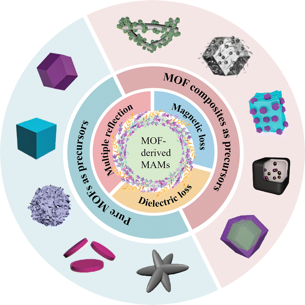 | ||
| Fig. 1 Schematic of EMWAMs based on MOF and MOF composites. Reproduced with permission from ref. 31–37. Copyright 2020, Wiley-VCH; Copyright 2023, Elsevier; Copyright 2024, Elsevier; Copyright 2022, RSC; Copyright 2020, Elsevier; Copyright 2024, Wiley-VCH; Copyright 2023, Elsevier. | ||
2. Electromagnetic response mechanism
During the transmission process, when the EMW encounters the absorber, it splits into three components: reflected EMW, transmitted EMW, and absorbed EMW.38,39 Excellent EMW absorption performance requires that the incident EMW be maximally dissipated inside the EMWAMs, minimizing transmission and reflection as much as possible, as both will cause secondary pollution to the environment and exacerbate the problem of electromagnetic pollution.40 Therefore, good impedance matching and EMW attenuation capability play an irreplaceable role in enhancing the EMW absorption performance.41,42 Among them, impedance matching is the key to determine whether EMWs can enter the interior of EMWAMs. The ideal impedance matching is that all the incident waves enter the inside of the absorber material without involving the reflection process. The attenuation capability is crucial in determining whether the EMW within an absorber can be effectively dissipated. A higher attenuation capability indicates that more electromagnetic energy is converted into heat or other forms of energy, facilitating its dissipation.8,43 Therefore, to achieve efficient EMW absorption performance, it is essential to coordinate both impedance matching and attenuation capacity. Only when both of these factors are optimized can the desired absorption effect be realized.For EMW absorption capacity we often use the reflection loss (RL) to characterize it. The stronger the EMW absorption ability, the less reflected waves will be, and the smaller the value of RL will be. The transmission line theory is usually used to calculate the RL value,44,45 the specific formula is as follows:
Z = |Zin/Zo| = |(μr/εr)1/2![[thin space (1/6-em)]](https://www.rsc.org/images/entities/char_2009.gif) tanh[j(2πfd/c)(μrεr)1/2]| tanh[j(2πfd/c)(μrεr)1/2]| |
| RL = 20 log|Zin − Zo|/(Zin + Zo)| |
The loss mechanism of EMWs can be roughly divided into two types, dielectric loss and magnetic loss.47,48 Dielectric loss generally occurs in carbon materials, polymers, non-magnetic metals and their metal oxides, and is evaluated by the tangent of dielectric loss (tanδε = ε′′/ε′). The real part of the dielectric constant indicates the capability to store energy, while the imaginary part of the dielectric constant indicates the capability to dissipate energy.49,50
Polarization relaxation loss and conductive loss are the two main sources of dielectric loss.51,52 Conductive loss refers to the directional motion of carriers within the medium under electric field conditions to form a current, which consumes electromagnetic energy through energy conversion. By the free electron theory 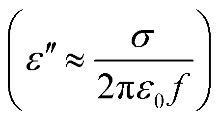 , the imaginary part of the dielectric constant is closely related to the conductivity, the larger the conductivity, the larger the imaginary part of the dielectric constant, the stronger the conductive loss capability.
In the frequency range of EMWs (2–18 GHz), polarization relaxation loss can be divided into interfacial polarization and dipole polarization. Interfacial polarization occurs at different phases or interfaces in the material and is attributed to the uneven charge distribution due to different crystal structures. Dipole oriented polarization is caused by the rearrangement of the electron cloud within the absorber in response to an applied electric field. According to Debye's theory, the relationship between ε′ and ε′′ can be expressed by the following equation when conductivity is not considered:

Magnetic losses mainly include eddy current effects, natural resonance, exchange resonance and hysteresis losses.54 The magnetic loss characteristics are described by the complex permeability (μr = μ′ − jμ′′), with the real (μ′) and imaginary (μ′′) parts of the complex permeability representing the energy storage capacity and loss capacity of the EMW, respectively. The loss is typically found in ferrites, magnetic metals and their metal compounds. In the 2–18 GHz range, hysteresis losses can be disregarded because irreversible magnetization can no longer be generated in weak magnetic fields.55 Eddy current effects play an important role in the mechanism of magnetic losses. In magnetic conductors, energy loss due to thermal effects of the current occurring in a closed loop, which causes eddy current effects. In order to measure the contribution of the eddy current effect, we introduce the eddy current coefficient (C0) to evaluate it.
| C0 = μ′′(μ′)−2f−1 = 2πσμ0d2 |
Natural resonance results from damped motion of the magnetic moment in the anisotropic magnetic field of the material. It is generally manifested by resonance peaks in the μ′ and μ′′ curves. The exchange resonance phenomenon exists when the particle size is submicron or even smaller. When the particle size becomes smaller, the frequency corresponding to the exchange peak will become larger.
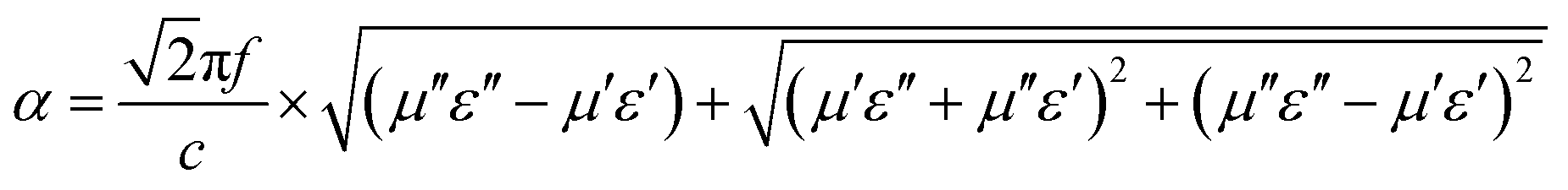
There are multiple loss mechanisms in EMWAMs that can be directly characterized by the attenuation constant (α).57 The α serves as a comprehensive evaluation of the total loss capability, the larger α is, the stronger the attenuation capability of the EMW. The formula is as follows:
In summary, developing high-performance EMWAMs requires careful coordination between impedance matching and the attenuation mechanism to prevent conflicts.
3. MOF-based EMWAMs
Depending on the number of metal element species in the MOF it can be roughly classified into two categories, including single-metal MOFs and multi-metal MOFs. Transition metals such as iron (Fe), cobalt (Co), and nickel (Ni) are widely used in the synthesis of metal-based MOFs due to their excellent magnetic properties. Consequently, EMWAMs that utilize magnetic metal-based MOFs exhibit both excellent magnetic and conductive loss characteristics. This makes them promising candidates for the development of efficient EMWAMs.3.1. EMWAMs based on single-metal MOFs
Among the EMWAMs based on single-metal MOFs, Fe-based MOFs are the most prevalent precursor materials. Liang et al. successfully synthesized porous Fe/C composites based on Fe-MOFs by a simple solvothermal reaction and in situ pyrolysis strategy (Fig. 2a).58a The size distribution of Fe-MOF precursors is relatively uniform, showing a shape of thin at both ends and thick in the middle, similar to a spindle (Fig. 2b). When the carbonization temperature was 900 °C, the porous Fe/C composite (FC-900) had a spindle-shaped carbon shell, which was attributed to the catalytic effect due to metal crystallization. The Fe metal crystals were uniformly distributed on the porous carbon shell and the lattice spacing of the metal crystals was 0.204 nm (Fig. 2c). The formation of a non-homogeneous interface between the porous carbon shell and the Fe nanoparticles significantly enhances interfacial polarization. Additionally, the incorporation of magnetic particles contributes to increased magnetic loss. The synergistic interaction between magnetic and dielectric losses, combined with the porous structure and good impedance matching, collectively optimizes the EMW absorption performance of the material. When the matching thickness is 1.5 mm, the minimum reflection loss (RLmin) is −37.63 dB, and the EAB covers the whole X-band (Fig. 2d).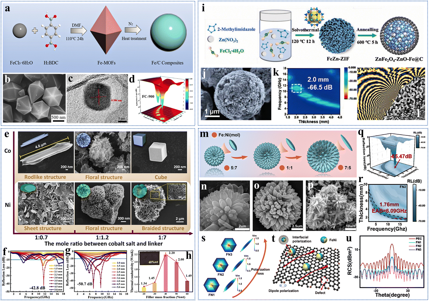 | ||
| Fig. 2 (a) Schematic diagram of the synthesis of Fe/C composites, (b) SEM image of Fe-MOFs, (c) TEM images of FC-900, (d) The 3D RL value for FC-900. Reproduced with permission from ref. 58a. Copyright 2022, Elsevier. (e) SEM images and model plots of six composite materials, 2D RL curves of (f) Co–C-f and (g) Ni–C-b, (h) The thermal conductivity of Ni–C-b as a function of resin content (40 wt% Ni–C-b flexible film for inset). Reproduced with permission from ref. 58b. Copyright 2024, Elsevier. (i) Schematic diagram of the synthesis of ZZFC, (j) SEM image, (k) The RL mapping of ZZFC-3, (l) Distribution of magnetic flux curves. Reproduced with permission from ref. 59. Copyright 2024, Wiley-VCH. (m) Schematic diagram of different volumes and petal sizes formed at different metal proportions, (n)–(p) SEM images of different metal proportions, (q) and (r) The RL mapping of Fe/Ni@C, (s) Model of the surface electric field distribution of a petal in Fe/Ni@C, (t) EMW attenuation mechanism of Fe/Ni@C, (u) RCS curves. Reproduced with permission from ref. 60. Copyright 2024, Elsevier. | ||
Generally, Co-based/Ni-based MOF has large specific surface area, high porosity and excellent magnetic properties, and is often used in the synthesis of monomeric MOF, so it has also attracted wide attention in the field of EMW absorption. The morphology of the MOF precursor will directly affect the EMW absorption performance.
Si et al. successfully constructed six anisotropic monometallic MOF composites with different morphologies using a simple regulatory method.58b By controlling the molar ratio of Co/Ni solvent to dimethylimidazole, the metal and ligand compete in the nucleation process to achieve anisotropic growth and optimize EMW absorption performance. Fig. 2e is the SEM image of a series of synthesized MOF derivatives. It can be seen that with the increase in the organic ligand doping amount, the Co-based MOF presents rod, flower, and cube morphology, while the Ni-based MOF presents sheet, flower, and braided morphology. Among Co-MOF, Co–C-f with a flower-like structure has the best absorbing performance, and its RLmin is −42.8 dB (Fig. 2f). The braided structure of Ni–C-b exhibits the strongest absorption characteristics among the six composites, achieving an RLmin of –50.7 dB at a thickness of 4.0 mm, and broadband absorption in the low-frequency range (Fig. 2g). The magnetic carbon derivatives obtained after carbonization have abundant oxygen-containing functional groups and defects, which increase the dipole polarization and promote the dissipation of EMW energy. A large number of conductive networks are formed on the surface of the derivatives, which promote electron migration and enhance conductive loss (Fig. 2h). The uniform distribution of Co/Ni metal in the derivatives will form a magnetic coupling effect and improve the magnetic response. In addition, Ni–C-b contains a large number of non-homogeneous interfaces, resulting in electron accumulation and enhanced interfacial polarization. Therefore, under the combined action of various loss mechanisms and anisotropic structures, the EMW attenuation performance is excellent.
3.2. EMWAMs based on multi-metal MOFs
EMWAMs based on single-metal MOFs lack diversity in both the number and type of metals, and the patterns are too fixed. Therefore, it is crucial for the development of multi-metal MOF precursors. The EMW absorption properties can be improved by modulating the content of different metals and changing the metal species.Huang et al. successfully synthesized ZnFe2O4–ZnO–Fe@C (ZZFC) microspheres with tailor-made heterogeneous interfaces by using a constrained growth strategy in which the bimetallic Fe–Zn-ZIF was first used as a template, followed by carbonization (Fig. 2i).59 A part of Fe2+ was reduced to Fe NPs and Zn2+ was converted to zinc oxide (ZnO) during the carbonation process. Another part of Fe2+ and Zn2+ react to form ZnFe2O4. The graphitized carbon layer is generated by Fe NPs catalyzed organic ligands. Miraculously, the generated carbon shell restricts the growth of particles such as ZnO, ZnFe2O4, etc. ZZFC microspheres are a hybrid structure consisting of single crystals and polycrystals. The composite material consists of a large number of nanoparticles bonded together, with an overall spherical shape and uniform size distribution (Fig. 2j). By adjusting the molar ratio of Fe to Zn, the assembly structure, conductivity, saturation magnetization, and absorption strength can be controlled, enabling the construction of bimetallic MOF composites with multiple attenuation mechanisms and customized heterogeneous interfaces.
High-density non-homogeneous interfaces were formed between a variety of nanoparticles and the carbon layer, including the C–ZnFe2O4 interface, the C–ZnO interface and the C–Fe interface, which significantly enhances the interfacial polarization effect. Additionally, the presence of many dislocations and defects in the crystals leads to the formation of dipole polarization, further enhancing the electromagnetic energy loss. The enhanced magnetic coupling network was constructed between the ZZFC microspheres, which improves the magnetic responsiveness to EMWs. With the collaboration of multiple loss mechanisms and good impedance matching, the ZZFC-3 microspheres have excellent electromagnetic dissipation capabilities. A RLmin of −66.5 dB was achieved at a matching thickness of 2.0 mm (Fig. 2k). The magnetic flux line distribution was simulated by phase information to explore the magnetic responsiveness in depth. As can be seen in Fig. 2l, the magnetic flux lines coming out of the ZZFC microspheres radiate outwards, indicating the magnetic coupling behavior between the ZZFC-3 microspheres. In addition, the absorption and reflection capabilities of the material in the real far field were verified through RCS simulation. The results demonstrate that the absorber with the ZZFC-3 composite coating exhibits excellent electromagnetic energy dissipation properties, further indicating that the material has promising potential for radar stealth applications.
By manipulating the synthesis conditions, the electromagnetic parameters can be optimized, allowing for effective adjustment of the EMW absorption characteristics. Liu et al. successfully synthesized flower-like Fe/Ni@C composites by using a competitive coordination strategy to precisely adjust the electromagnetic parameters.60 First, flower-like FeNi-MOF-74 precursors with different volumes and petal sizes were prepared by controlling reaction time, hydrothermal temperature and metal ion ratio during synthesis (Fig. 2m). Then, the temperature of precursor carbonization was adjusted to optimize the degree of graphitization, and the Fe/Ni@C derivatives with excellent EMW absorption properties were obtained. When the concentration ratio of metal ions is different, it will directly affect the volume of the derivatives and the size of the petal. According to the SEM image, Fe/Ni@C derivatives are formed by a large number of low-dimensional petals spliced together. As the ratio of Fe to Ni increased, both the volume and petal size of the derivative increased (Fig. 2n–p). In addition, after reaching 620 °C, the TG curve remains unchanged with increasing temperature, indicating excellent thermal stability within the range of 600–800 °C. This finding indicates that MOF-based EMWAMs can be produced in a controlled manner by adjusting the pyrolysis temperature. The best EMW absorption performance is obtained when the carbonization temperature is 700 °C and the ratio of Fe to Ni metal is 1:1, the RLmin is –65.47 dB and the EAB is 6.09 GHz (Fig. 2q and r).
The excellent wave-absorbing capability of the derivative mainly depends on the following aspects. First, the constructed flower structure, which features a large specific surface area, facilitates the formation of a high-density conductive network, accelerates electronic transitions, promotes multiple reflections and scattering of EMW, and enhances conductive loss. Additionally, the degree of graphitization can be improved by adjusting the carbonization temperature, further augmenting conductive loss. Second, as the petal becomes larger, its curvature also increases, promoting the tip effect and resulting in an imbalance in electron distribution (Fig. 2s). Furthermore, the derivatives contain a significant number of defects and functional groups, which collectively enhance dipole polarization (Fig. 2t). Third, there exists a rich heterogeneous interface between the magnetic FeNi alloy and carbon, which improves the interface polarization effect and increases the loss of EMW energy (Fig. 2t). Finally, the introduction of FeNi alloys optimizes the impedance matching characteristics while simultaneously increasing magnetic loss.
The feasibility of the absorber for practical applications is further investigated through RCS simulation. Compared to a bare metal plate, the metal plate coated with absorbing material demonstrates a significant capacity for EMW absorption. By testing the scattered signals from various angles, it was observed that when the carbonization temperature is 700 °C and the ratio of Fe to Ni is 1:1, the resulting coating model produces very low scattered signals across all angles. This finding further confirms that the derivative effectively absorbs EMW and possesses practical value (Fig. 2u).
4. EMWAMs based on MOF composites
Compositing MOFs with other materials as precursors can further optimize the EMW absorption properties. Compared with pure MOF precursors, EMWAMs based on MOF composites as precursors can regulate dielectric genes more effectively and precisely. The strategies for preparing MOF composites will be introduced in the following three categories: doping metal nanoparticles, introducing low-dimensional materials, and designing core–shell structures.4.1. Doped metal nanoparticles
The problem of impedance matching imbalance occurs in most MOF-based EMWAMs. The most direct and effective strategy to solve the problem is to introduce metal nanoparticles to improve the magnetic properties.Shu et al. successfully constructed nitrogen-doped CoFe alloy@C-CNTs nanocomposites using two strategies: aging and carbonization.61a First, Fe3O4 was synthesized through a solvothermal method. Next, Fe3O4 was introduced into a mixed solution containing Co2+, Zn2+, and 2-MIM, resulting in the synthesis of CoZn-MOFs/Fe3O4 precursors via a room temperature aging strategy. Finally, the CoFe alloy@C-CNTs were formed through a carbonization process (Fig. 3a). Fe3O4 was chosen because of its low price, strong magnetism and good chemical stability. The overall morphology of the derivatives showed four-pointed stars (Fig. 3c), and many carbon nanotubes (CNTs) catalyzed by cobalt grew on the non-smooth surface (Fig. 3b). After carbonization, the Fe3O4 microspheres are converted into CoFe nanoalloys and are uniformly dispersed within the porous carbon matrix (Fig. 3d).
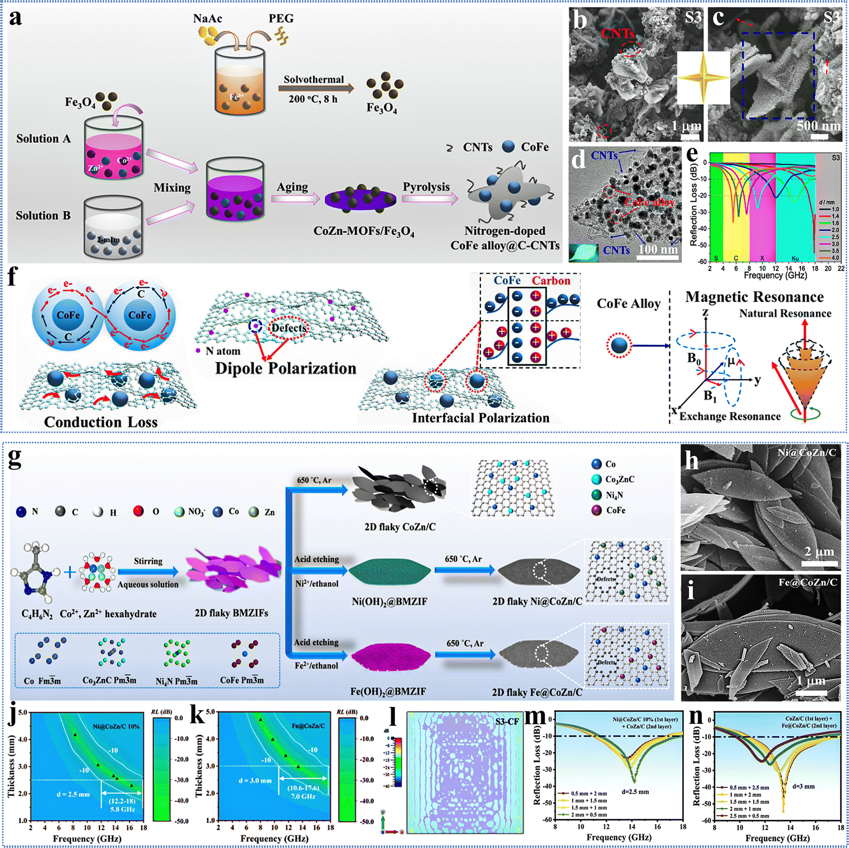 | ||
| Fig. 3 (a) Schematic illustration of the synthesis of CoFe alloy@C-CNTs, (b) and (c) SEM images, (d) TEM images, (e) 2D RL curves of S3, (f) diagram of the EMW absorption mechanism of a composite material. Reproduced with permission from ref. 61a. Copyright 2022, Elsevier. (g) Schematic diagram of the synthesis of 2D flaky nanocomposites, SEM images of (h) Ni@CoZn/C and (i) Fe@CoZn/C, The RL maps (j) Ni@CoZn/C and (k) Fe@CoZn/C, (l) electric field distribution of S3-CF, 2D RL curves of (m) S2-NC and (n) S3-CF. Reproduced with permission from ref. 61b. Copyright 2023, Elsevier. | ||
By changing the carbonization temperature, the influence of temperature on the EMW absorption performance of the composite was investigated. The results show that with the increase of carbonization temperature, the conductivity, graphitization degree and saturation magnetization of the derivatives increase gradually, and the specific surface area increases first and then decreases. Therefore, the carbonization temperature can directly affect the EMW attenuation performance of the composite. The derivatives exhibited the best EMW dissipation at a carbonization temperature of 700 °C, with an RLmin of –54.5 dB and an EAB of 5.0 GHz at a matching thickness of 1.4 mm (Fig. 3e). Its excellent wave absorption performance can be attributed to several factors (Fig. 3f). Firstly, the porous structure can optimize impedance matching and promote EMW attenuation while increasing EMW incidence. Secondly, CNTs formed at the edges of the carbon skeleton contribute to the construction of conductive networks and promote the conversion of EMW energy into heat energy for dissipation. Thirdly, the surface of porous graphitized C contains numerous defects, and due to the doping of N atoms, there are electronegativity differences between C and N atoms, forming rich dipoles, which can enhance dipole polarization. Fourthly, a rich heterogeneous interface exists between the CoFe alloy and C, leading to charge accumulation and the formation of structures similar to capacitors, which significantly enhances the interface polarization effect. Finally, the formation of CoFe alloys adds an additional magnetic loss.
Another effective method for introducing metal ions into MOFs is ion penetration. Pan et al. mixed 2D bimetallic MOF precursors (BMZIF) with solutions containing different metal ions (Ni2+, Fe2+) and successfully loaded magnetic nanoparticles onto the carbon skeleton through acid etching and carbonization. This process resulted in the formation of porous sheet MOF-carbon-based magnetic nanocomposites (Ni@CoZn/C and Fe@CoZn/C) (Fig. 3g).61b In ethanol solution, Ni2+ and Fe2+ hydrolyze to form Ni(OH)2 and Fe(OH)2 precipitates, respectively, which adhere to the surface of BMZIF. The hydrolysis reaction also slightly acidifies the solution, promoting the dissociation of BMZIF. SEM images reveal that both Fe@CoZn/C and Ni@CoZn/C exhibit a 2D flake hexagonal morphology similar to their precursors, with nanoparticles uniformly distributed within the carbon skeleton (Fig. 3h and i). After carbonization, the thickness of the metal-doped composite material becomes thinner, and the structure will be broken accordingly, particularly evident in Fe@CoZn/C (Fig. 3i). The results show that doping metal and adjusting the filling amount can affect the EMW absorption properties of the composites. Ni@CoZn/C demonstrates strong microwave absorption with an RLmin of −45 dB and an EAB of 5.8 GHz at a filling amount of 10 wt% (Fig. 3j). In contrast, the optimal wave-absorbing performance occurs with the Fe@CoZn/C composite at a filling of 15 wt%, achieving an RLmin of −61.5 dB and an EAB of 7.0 GHz (Fig. 3k).
A double-coated absorber, designed based on impedance gradient theory, achieves the goal of thinner and wider EAB. This double layer significantly enhances EMW absorption and broadens the EAB. The simulation results of the electric field distribution on the surface of the double-layer absorber indicate that the electric field distribution is uneven. The electric field strength is weakest in the middle, while the EMW absorption capacity is strongest (Fig. 3l). Adjusting the coating thickness optimizes impedance matching. At 2.5 mm total thickness, S2-NC (10% Ni@CoZn/C 2 mm and CoZn/C 0.5 mm) achieves an EAB of 6.32 GHz (Fig. 3m). Increasing to 3 mm results in an RLmin of −54.5 dB for S3-CF (Fe@CoZn/C 2 mm and CoZn/C 1 mm), achieving a broadband absorption of 7.1 GHz (Fig. 3n). RCS simulations further confirm excellent EMW absorption performance at all angles. The absorption mechanism of 2D flaky porous derivatives is primarily evident in several aspects. First, acid corrosion generates a significant number of carbon defects and interfaces, which increases polarization relaxation loss. Second, the design of an impedance gradient can reduce reflected waves, enhance impedance matching characteristics, and improve the EMW absorption and attenuation performance. Finally, the formation of ferromagnetic products contributes additional magnetic losses.
4.2. Introduce low-dimensional materials
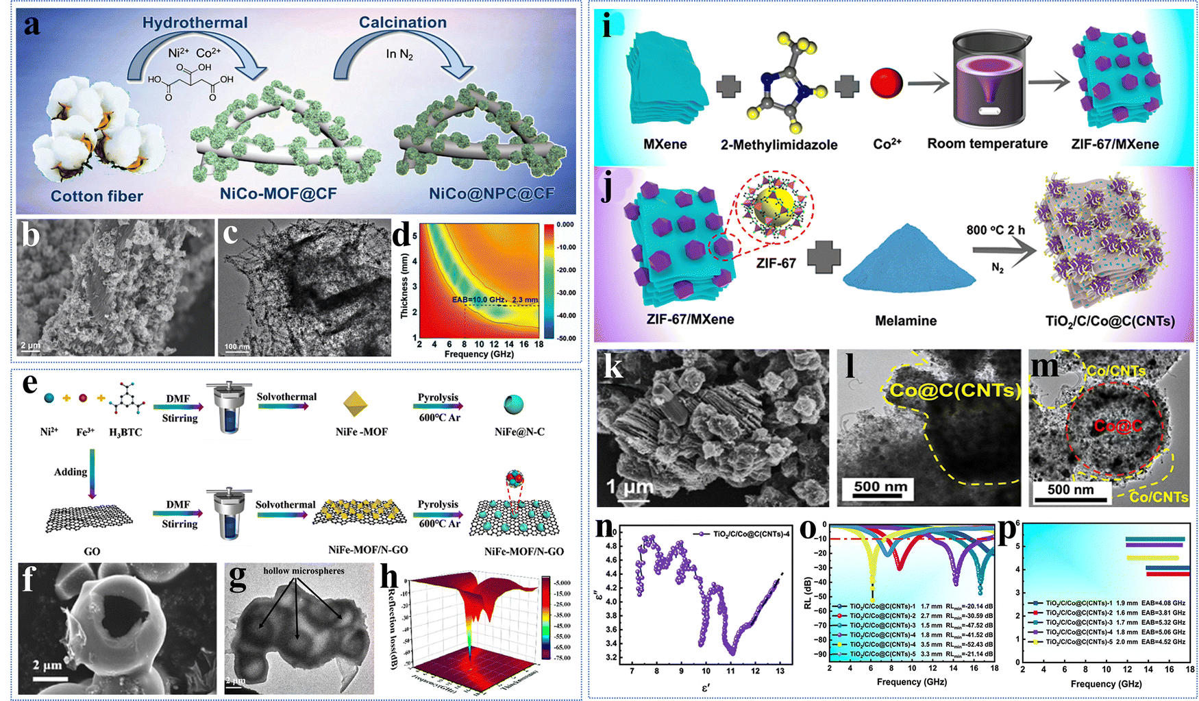
Nowadays, most of the MOF-based EMWAMs only improve the conductivity of the derivatives, but are unable to build a conductive network and therefore cannot achieve the effect of accelerating the electron transport on the surface. This phenomenon makes the development of MOF in the field of EMW absorption not smooth. One of the most effective ways to address the above problems is to develop MOF-based EMWAMs with low-dimensional conducting carbon materials by compounding MOF with low-dimensional materials.Traditional carbon nanomaterials face challenges such as high costs, complex synthesis processes, and environmental pollution resulting from industrial production. Therefore, it is crucial to select low-cost, high-absorption carbon materials. Biomass materials have attracted much attention due to their affordability, minimal environmental impact, high conductivity, and low density. Wang et al. successfully prepared porous NiCo@NPC@CF composites by first growing flower-like Ni–Co-MOF particles in situ on biomass cotton by hydrothermal method, followed by carbonization (Fig. 4a).34 The material consists of NiCo@C nanoflowers and porous carbon fibres. Cotton was transformed into hollow carbon fibres during the carbonization process and had a rough surface containing a large number of folds (Fig. 4b). The NiCo@C nanoparticles maintained a flower-like morphology, which was tightly attached to the surface of the carbon fibres and had a large number of CNTs catalytically formed by NiCo alloy particles growing on their surface (Fig. 4c). The conductive network derived from biomass cotton and CNTs accelerates the electron transport and increases the dielectric loss. The layered porous structure optimizes the impedance matching performance while contributing to multiple reflections of EMWs. Rich interfaces are formed between carbon fibres, CNTs, and NiCo alloys to enhance the interfacial polarization loss. In addition, the formation of NiCo alloy particles leads to magnetic loss. Therefore, with the joint collaboration of the layered porous structure and multiple loss mechanisms, the NiCo@NPC@CF composites have excellent EMW absorption performance with a RLmin of −46.5 dB, and achieve an ultra-wide EAB (10.0 GHz, 8.0–18.0 GHz) at 2.3 mm thickness (Fig. 4d).
 | ||
| Fig. 4 (a) Schematic diagram of the synthesis of NiCo@NPC@CF, (b) the SEM image, (c) the TEM image, (d) the 2D curves of NiCo@NPC@CF-700. Reproduced with permission from ref. 34. Copyright 2022, RSC. (e) Schematic illustration of the preparation of NiFe@N–C/rGO, (f) the SEM image, (g) TEM image of NiFe@N–C/rGO-30, (h) 3D RL maps of NiFe@N–C/rGO-30. Reproduced with permission from ref. 62. Copyright 2023, Elsevier. (i) and (j) Schematic diagram of the synthesis of TiO2/C/Co@C(CNTs), (k) SEM image, (l) and (m) TEM images, (n) Cole–Cole image of TiO2/C/Co@C(CNTs)-4, (o) and (p) comparative plots of RL and EAB of TiO2/C/Co@C (CNT) composites. Reproduced with permission from ref. 33. Copyright 2024, Elsevier. | ||
Zhao et al. successfully prepared hollow microsphere structure NiFe@N–C/rGO by compositing graphene oxide and Ni–Fe-MOF via solvothermal method and high-temperature carbonization process (Fig. 4e).62 During the high-temperature carbonization process, the structure of octahedral Ni–Fe-MOF collapsed and the dimensions contracted, resulting in the formation of a hollow sphere with rough surface (Fig. 4f). The introduction of graphene further reinforced the hollow structure (Fig. 4g). The constructed hollow porous structure promotes multiple reflections and scattering of EMW. A large number of non-homogeneous interfaces and defects are formed between N-rGO and NiFe@N–C, which contribute to the enhancement of the dielectric loss. In addition, the formation of conductive networks as well as the enhancement of magnetic losses contribute positively to the EMW attenuation capability of the materials. As a result, the optimized composite exhibits excellent EMW attenuation performance with RLmin of −72.28 dB and EAB of 5.25 GHz at a thickness of 2.46 mm (Fig. 4h).
Ye et al. successfully prepared CNT-modified TiO2/C/Co@C composites (TiO2/C/Co@C (CNTs)) through an in situ growth and carbonization process. The structure is based on ZIF-67/MXene as raw material, and CNTs grown on its surface under the action of melamine, which has a hierarchical hybrid network structure (Fig. 4i and j).33 The derivatives maintain the accordion-like morphology of the feedstock MXene, in which the polyhedral ZIF-67 surface shrinks and becomes smaller in size, tightly adsorbed on the surface of MXene or inserted into the layer-to-layer intervals (Fig. 4k). MXene is converted to TiO2 and graphitic carbon during the carbonization process, and Co nanoparticles converted from Co2+ in ZIF-67 serve as a catalyst for the catalytic formation of the CNTs. The TEM images show that the ZIF-67 surface has abundant Co@C composites with many CNTs growing on its surface, and there is an interface between Co@C and MXene (Fig. 4l and m). Numerous Cole–Cole semicircles and straight-line tails are observed in the ε′ − ε′′ functional relationship curves, indicating that the material has abundant polarization relaxation and conductive losses (Fig. 4n).
The presence of a large number of defects and functional groups in the carbonated derivatives enhances the dipole polarization. Multi interfacial effects can be achieved between TiO2, CNTs, metal Co particles and carbon flakes to improve the interfacial polarization loss, which is conducive to the attenuation for EMW. The presence of CNTs can form a three-dimensional conductive network to promote the rapid transfer of electrons, optimizing impedance matching while improving the conductive loss capability. In addition, the generation of metal Co particles improves the magnetic loss of the composites, which is conducive to the improvement of EMW dissipation ability. As a result, the optimized TiO2/C/Co@C (CNTs) composites achieve strong EMW attenuation (−52.43 dB) and wide EAB (5.06 GHz) at a thin thickness (Fig. 4o and p).
4.3. Design the core–shell structure
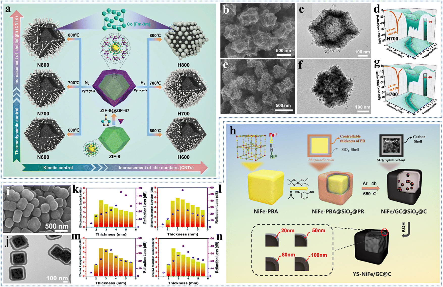
The design of core–shell structures has become a key strategy in the development of EMWAMs to enhance the EMW absorption performance by integrating different core and shell components. The core–shell structure is characterized by the encapsulation of the central core material by the shell, allowing for complementary properties.Zhou et al. successfully prepared a series of N-doped carbon-coated cobalt nanoparticles (Co@NC) by controlling the pyrolysis atmospheres (N2 and H2) and pyrolysis temperatures using ZIF-8@ZIF-67 as the precursor (Fig. 5a).36 The lattice structure of ZIF-67 is similar to that of ZIF-8, and so ZIF-67 can be grown by nucleation on ZIF-8. It can be seen in SEM and TEM images that Co@NC showed a dodecahedral structure when carbonized at different pyrolytic atmospheres (Fig. 5b and e). The structure size distribution between 400–450 nm and CNTs growing on the surface (Fig. 5c and f). The CNTs are formed due to the catalysis of Co nanoparticles. Because of the reducing nature of H2, there is an increase in the number of Co nanoparticles generated and hence the number of CNTs is more (Fig. 5e and f). The presence of CNTs helps in the formation of conductive network and enhances the conductive loss. The abundant interfacial polarization is then due to the oxidation of the surface metal. In addition, N-atom doping, defects and the presence of graphitized carbon provide dipole polarization, which facilitates the attenuation of EMWs. By optimizing the components and structure, Co@NC achieves the best EMW absorption performance with an RLmin of −64.0 dB and a maximum EAB of 5.4 GHz in a pyrolytic atmosphere of H2 and at a temperature of 700 °C (Fig. 5d and g).
 | ||
| Fig. 5 (a) Schematic diagram of the synthesis of Co@NC, SEM and TEM images of (b) and (c) N700, (e) and (f) H700, 3D RL maps of (d) N700 and (g) H700. Reproduced with permission from ref. 36. Copyright 2024, Wiley-VCH. (h) Schematic diagram of the synthesis of YS-NiFe/GC@C, (i) SEM image, (j) TEM image of NiFe/GC@C-2, (k)–(n) EABmax and RLmin values of NiFe/GC@C composites at different thicknesses. Reproduced with permission from ref. 37. Copyright 2023, Elsevier. | ||
Tang et al. successfully constructed NiFe/GC@SiO2@C composites with yolk shell structure by using amorphous carbon shells with different thicknesses as a capping layer encapsulating NiFe-PBA through a hierarchical building process (Fig. 5h).37 The amorphous carbon shell can avoid the collapse of the structure, and its thickness can be controlled by adjusting the thickness of phenolic resin (PR). SiO2 acts as a hard template to co-maintain the cubic structure on the one hand, and on the other hand, it forms a cavity in the carbonization process to improve the attenuation of EMWs. The SEM and TEM images show that the composites have a yolk–shell cubic structure without agglomeration, and the thicknesses of the carbon shells are 20, 50, 80, and 100 nm, respectively (Fig. 5i and j). The yolk–shell structure and the adjustable thickness of the carbon layer promote the attenuation of EMWs while optimizing the impedance matching. The formation of abundant heterogeneous interfaces and conductive networks between the carbon shells and the NiFe alloy enhances the dielectric loss and helps to convert the EMW energy into heat or other forms of energy. A large number of N heteroatoms and defects enhance the dipole polarization effect. In addition, magnetic particles lead to magnetic losses and promote energy decay. NiFe/GC@C has excellent microwave absorption properties due to the multiple loss mechanism and yolk shell structure. The best performance exists at an amorphous carbon shell thickness of 50 nm, where RLmin can reach −56.3 dB and EAB of 5.64 GHz (Fig. 5k–n).
In Table 1, we list the EMW absorption characteristics of all the EMWAMs mentioned above, comparing RL, EAB, thickness, and filling ratio.
| EMWAMs | T (°C) | RL (dB) | d (mm) | EAB (GHz) | d (mm) | Ratio (wt%) | Ref. |
|---|---|---|---|---|---|---|---|
| Fe/C | 900 | −37.63 | 1.5 | 4.4 | 1.5 | 30 | 58a |
| Co–C-f | 650 | −42.8 | — | 2.3 | — | 80 | 58b |
| Ni–C-b | 650 | −50.7 | 4 | 6 | — | 80 | 58b |
| ZnFe2O4–ZnO–Fe@C | 600 | −66.5 | 2 | — | — | — | 59 |
| Fe/Ni@C | 700 | −65.47 | 1.56 | 6.09 | 1.76 | — | 60 |
| CoFe alloy@C-CNTs | 700 | −54.5 | 1.4 | 5.0 | 1.6 | — | 61a |
| Ni@CoZn/C | 650 | −45 | 2.5 | 5.8 | 2.5 | 10 | 61b |
| Fe@CoZn/C | 650 | −61.5 | 4.5 | 7.0 | 3 | 15 | 61b |
| NiCo@NPC@CF | 700 | −46.5 | 3.5 | 10.0 | 2.3 | 30 | 34 |
| NiFe@N–C/rGO-30 | 600 | −72.28 | 2.46 | 5.25 | 1.84 | 20 | 62 |
| TiO2/C/Co@C (CNTs) | 800 | −52.43 | 3.5 | 5.06 | 1.8 | — | 33 |
| Co@NC | 700 | −64.0 | 2.8 | 5.4 | 2.2 | — | 36 |
| NiFe/GC@SiO2@C | 650 | −56.3 | 3.5 | 5.64 | 3.5 | 40 | 37 |
5 Conclusion and outlook
MOF-based EMWAMs have become the ‘seed’ players in the field of EMW absorption due to the uniqueness of their structures, controllable chemical compositions, and diverse functions. In this paper, we systematically review the research progress of various MOF-based EMWAMs, including the preparation strategy, absorption mechanism, and wave-absorbing performance. According to the type of precursor, they are classified into two categories: pure MOF-based EMWAMs and MOF composites-based EMWAMs. MOF-based EMWAMs usually have good impedance matching properties and multiple loss mechanisms, and have great prospects for development in the field of EMW absorption.Although the research on MOF-based EMWAMs has achieved certain results, there are still some problems and challenges that we need to solve. First, increasing the diversity of MOF species is important for the development of novel EMWAMs. The number of MOF precursors explored to date is quite limited in terms of both species and morphology. The predominant types of MOF precursors include PBA, ZIF-8, MIL-88, UIO-66, and MOF-74. There is an urgent need to investigate MOFs based on other components, such as lanthanide MOFs. Regarding morphological regulation, the variety of morphological types for MOF-based EMWAMs are significantly restricted. For instance, carbon and inorganic ferrites can form a diverse array of core–shell structures, including tubular core–shells, multi-core–shells, nuclear multi-shells, yolk shells, and hexagonal core–shells. In contrast, the morphology of MOF-based EMWAMs is limited to nuclear shells and yolk shells. Therefore, it is crucial to expand the diversity of MOF-based EMWAMs.
Second, continue to pay attention to the advancements in conductive MOFs. Most commonly used MOF precursor templates exhibit poor electrical conductivity. The most direct and effective solution to this issue is pyrolysis; however, the impact of high temperatures on the structure is significant. This challenge has hindered researchers from exploring the relationship between structure and microscopic mechanisms, which has severely limited its development in the field of EMW. Conductive MOFs can be utilized directly to prepare EMWAMs without the need for pyrolysis. Additionally, they offer advantages such as good stability, low cost, and a well-defined microstructure, which aids in elucidating the absorption mechanisms in greater detail. Therefore, it is imperative to continue in-depth studies of conductive MOFs.
Third, it is urgent to carry out atomic engineering to achieve precise expression of “genes”. Electromagnetic response is equivalent to the “biological gene” of electromagnetic absorbing materials. Improving the electromagnetic attenuation ability of EMWAMs can be achieved by regulating “dielectric genes” and “magnetic genes”. The “genes” are recombined and selectively encoded by hybridization to achieve precise tailoring of the structure and composition of the MOF precursor. The precise expression of dielectric and magnetic “genes” is conducive to size control, heterogeneous structure formation and defect engineering.
Fourth, the EMW absorption mechanism needs to be further explored. The EMW absorption ability is a complex composition, including multiple reflection and scattering, impedance matching, dielectric loss and magnetic loss. However, the compositional relationship and distribution between them are not yet known. Therefore, the intrinsic relationship between the microstructure and the attenuation mechanism needs to be deeply explored, which is expected to lead to accurate synthesis.
Fifth, the development of multifunctional integration and electromagnetic devices is an important development direction. In order to meet the demands of practical application scenarios, EMWAMs need to satisfy strong absorption and wide bandwidth with multifunctionality and strong stability. It is critical to design EMWAMs with a variety of multiple excellent properties. From materials to applications can be realized through electromagnetic functional devices. A system or device designed using electromagnetic principles with a certain function is called an electromagnetic functional device. It enables the sensing, control and transmission of EMWs. So far, they have been used in the fields of filters, sensors, microwave drivers, antennas and so on. However, single-function electromagnetic devices cannot be applied to complex application scenarios, so it is crucial to design multifunctional electromagnetic devices to meet the requirements of the scenarios while contributing to the integration of the devices.
Finally, the realization of large-scale production remains our goal. Most MOF composites are available in powder form, which presents several challenges, including low yield, high costs, and environmental pollution. These issues significantly restrict their application in various fields, including people's livelihood and military use. Therefore, the emphasis should be on developing environmentally friendly, cost-effective, stable, and easily prepared EMWAMs with high yields. We must strive to overcome these challenges promptly to achieve large-scale production of MOF-based EMWAMs.
In summary, there is still a long way to go in the research of MOF-based EMWAMs. Most of the current studies are still limited to the laboratory environment and cannot be applied to practical and industrial production. We hope that this review can provide ideas and directions for future research on MOF-based EMWAMs. We believe that with the persistence of researchers around the world, all these problems and challenges will be overcome and MOF-based EMWAMs will be widely used in the field of EMWs.
Conflicts of interest
The authors declare no conflict of interest.Acknowledgements
This work was financially supported by the NNSF of China (Grant No. 12074095, 12374392, 52403351, No. 52373280, 52177014), the Heilongjiang Provincial Science Foundation for Distinguished Young Scholars (JQ2022A002), and the Joint Guidance Project of the Natural Science Foundation of Heilongjiang Province (LH2023A012).References
- J. Yan, Q. Zheng, S. Wang, Y. Tian, W. Gong, F. Gao, J. Qiu, L. Li, S. Yang and M. Cao, Multifunctional Organic–Inorganic Hybrid Perovskite Microcrystalline Engineering and Electromagnetic Response Switching Multi-Band Devices, Adv. Mater., 2023, 35, 2300015 CrossRef CAS PubMed
.
- G. Fang, C. Liu, M. Xu, X. Zhang, Y. Wu, D. Kim and G. Ji, The Elaborate Design of Multi-Polarization Effect by Non-Edge Defect Strategy for Ultra-Broad Microwave Absorption, Adv. Funct. Mater., 2024, 34, 2404532 CrossRef CAS
- X. Zhang, M. Zhang, M. Wang, L. Chang, L. Li and M. Cao, Metal Single-Atoms Toward Electromagnetic Wave-Absorbing Materials: Insights and Perspective, Adv. Funct. Mater., 2024, 34, 2405972 CrossRef CAS
- J. Xu, B. Li, Z. Ma, X. Zhang, C. Zhu, F. Yan, P. Yang and Y. Chen, Multifunctional Film Assembled from N-Doped Carbon Nanofiber with Co–N4–O Single Atoms for Highly Efficient Electromagnetic Energy Attenuation, Nano-Micro Lett., 2024, 16, 240 CrossRef CAS PubMed
- Y. Wang, Y. Wang, J. Shu, W. Cao, C. Li and M. Cao, Graphene Implanted Shape Memory Polymers with Dielectric Gene Dominated Highly Efficient Microwave Drive, Adv. Funct. Mater., 2023, 33, 2303560 CrossRef CAS
-
(a) S.-Q. Zhu, J.-C. Shu and M.-S. Cao, Tailorable MOF architectures for high-efficiency electromagnetic functions, Mater. Chem. Front., 2021, 5, 6444–6460 RSC
- J. Xiao, B. Zhan, M. He, X. Qi, X. Gong, J. Yang, Y. Qu, J. Ding, W. Zhong and J. Gu, Interfacial Polarization Loss Improvement Induced by the Hollow Engineering of Necklace-like PAN/Carbon Nanofibers for Boosted Microwave Absorption, Adv. Funct. Mater., 2024, 2316722 CrossRef
- G. Yu, G. Shao, R. Xu, Y. Chen, X. Zhu and X. Huang, Metal–Organic Framework-Manipulated Dielectric Genes Inside Silicon Carbonitride toward Tunable Electromagnetic Wave Absorption, Small, 2023, 19, 2304694 CrossRef CAS PubMed
-
(a) S. Ren, H. Yu, L. Wang, Z. Huang, T. Lin, Y. Huang, J. Yang, Y. Hong and J. Liu, State of the Art and Prospects in Metal-Organic Framework-Derived Microwave Absorption Materials, Nano-Micro Lett., 2022, 14, 68 CrossRef CAS
- X. Xiong, H. Zhang, H. Lv, L. Yang, G. Liang, J. Zhang, Y. Lai, H.-W. Cheng and R. Che, Recent progress in carbon-based materials and loss mechanisms for electromagnetic wave absorption, Carbon, 2024, 219, 118834 CrossRef CAS
-
(a) J. Du, T. Li, Z. Xu, J. Tang, Q. Qi and F. Meng, Structure–Activity Relationship in Microstructure Design for Electromagnetic Wave Absorption Applications, Small Structures, 2023, 4, 2300152 CrossRef CAS
- J. Zhou, Y. Sui, N. Wu, M. Han, J. Liu, W. Liu, Z. Zeng and J. Liu, Recent Advances in MXene-Based Aerogels for Electromagnetic Wave Absorption, Small, 2024, 2405968 CrossRef CAS PubMed
-
(a) X. Su, M. Han, Y. Liu, J. Wang, C. Liang and Y. Liu,
In situ construction of nitrogen-doped reduced graphene oxide@carbon nanofibers towards the synergetic enhancement of their microwave absorption properties via integrating point defects and structure engineering, J. Colloid Interface Sci., 2022, 628, 984–994 CrossRef CAS PubMed
- T. Lin, H. Yu, L. Wang, Q. Ma, H. Huang, L. Wang, M. A. Uddin, F. Haq and D. A. Lemenovskiy, A study on the fabrication and microwave shielding properties of PANI/C60 heterostructures, Polym. Compos., 2021, 42, 1961–1976 CrossRef CAS
- Y. Zhang, Z. Yang, T. Pan, H. Gao, H. Guan, J. Xu and Z. Zhang, Construction of natural fiber/polyaniline core–shell heterostructures with tunable and excellent electromagnetic shielding capability via a facile secondary doping strategy, Composites, Part A, 2020, 137, 105994 CrossRef CAS
- A. Nazir, H. Yu, L. Wang, Y. He, Q. Chen, B. U. Amin and D. Shen, Electromagnetic interference shielding properties of ferrocene-based polypyrrole/carbon material composites, Appl. Phys. A: Mater. Sci. Process., 2020, 126, 749 CrossRef CAS
- C. Chang, X. Yue, B. Hao, D. Xing and P.-C. Ma, Direct growth of carbon nanotubes on basalt fiber for the application of electromagnetic interference shielding, Carbon, 2020, 167, 31–39 CrossRef CAS
- G. Sun, B. Dong, M. Cao, B. Wei and C. Hu, Hierarchical Dendrite-Like Magnetic Materials of Fe3O4, γ-Fe2O3, and Fe with High Performance of Microwave Absorption, Chem. Mater., 2011, 23, 1587–1593 CrossRef CAS
- J. Pan, H. Guo, M. Wang, H. Yang, H. Hu, P. Liu and H. Zhu, Shape anisotropic Fe3O4 nanotubes for efficient microwave absorption, Nano Res., 2020, 13, 621–629 CrossRef CAS
-
(a) M. Qin, L. Zhang and H. Wu, Dielectric Loss Mechanism in Electromagnetic Wave Absorbing Materials, Adv. Sci., 2022, 9, 2105553 CrossRef CAS
- L.-H. Yao, J.-G. Zhao, Y.-C. Wang and M.-S. Cao, Manipulating electromagnetic response for tunable microwave absorption, electromagnetic interference shielding, and device, Carbon, 2023, 212, 118169 CrossRef CAS
- M.-Q. Wang and M.-S. Cao, Perspectives on metal-organic framework-derived microwave absorption materials, J. Mater. Sci. Technol., 2025, 214, 37–52 CrossRef CAS
-
(a) M. Zhang, Q. Zheng, M.-S. Cao and C. Han, Regulating long-range travelling electrons for simultaneous electromagnetic absorption and interference shielding of Co@C nanofibers, Carbon, 2023, 214, 118338 CrossRef CAS
- A. J. Albaaji, E. G. Castle, M. J. Reece, J. P. Hall and S. L. Evans, Effect of ball-milling time on mechanical and magnetic properties of carbon nanotube reinforced FeCo alloy composites, Mater. Des., 2017, 122, 296–306 CrossRef CAS
- R. Guil-Lopez, R. M. Navarro and J. L. G. Fierro, Controlling the impregnation of nickel on nanoporous aluminum oxide nanoliths as catalysts for partial oxidation of methane, Chem. Eng. J., 2014, 256, 458–467 CrossRef CAS
- L. Wu, M. Zhao, X. Xin, Q. Ye, K. Zhang and Z. Wang, Core–Shell Composite MIL-101(Cr)@TiO2 for Organic Dye Pollutants and Vehicle Exhaust, Molecules, 2023, 28, 5530 CrossRef CAS PubMed
- C. Huang, X. Xu, J. Fu, D.-G. Yu and Y. Liu, Recent Progress in Electrospun Polyacrylonitrile Nanofiber-Based Wound Dressing, Polymers, 2022, 14, 3266 CrossRef CAS PubMed
-
(a) Y. M. Jung, J. H. Choi, D. W. Kim and J. K. Kang, 3D Porous Oxygen-Doped and Nitrogen-Doped Graphitic Carbons Derived from Metal Azolate Frameworks as Cathode and Anode Materials for High-Performance Dual-Carbon Sodium-Ion Hybrid Capacitors, Adv. Sci, 2023, 10, 2301160 CrossRef CAS
- F. H. Gourji, T. Rajaramanan, A. Kishore, M. Heggertveit and D. Velauthapillai, Hierarchical Cube-in-Cube Cobalt–Molybdenum Phosphide Hollow Nanoboxes Derived from the MOF Template Strategy for High-Performance Supercapacitors, ACS Omega, 2023, 8, 23446–23456 CrossRef CAS PubMed
- J. Lin, Q. Wu, J. Qiao, S. Zheng, W. Liu, L. Wu, J. Liu and Z. Zeng, A review on composite strategy of MOF derivatives for improving electromagnetic wave absorption, iScience, 2023, 26, 107132 CrossRef CAS PubMed
- M. Huang, L. Wang, K. Pei, W. You, X. Yu, Z. Wu and R. Che, Multidimension-Controllable Synthesis of MOF-Derived Co@N-Doped Carbon Composite with Magnetic-Dielectric Synergy toward Strong Microwave Absorption, Small, 2020, 16, 2000158 CrossRef CAS
- Q. Ma, R. Qiang, Y. Shao, X. Yang, R. Xue, B. Chen, Y. Chen and S. Feng, MOF-derived Co–C composites with 3D star structure for enhanced microwave absorption, J. Colloid Interface Sci., 2023, 651, 106–116 CrossRef CAS PubMed
- X. Ye, Y. Lv, L. Zhang, H. Chen, S. Chen, Y. Wu, L.-A. Ma and Q. Wang, Hierarchical carbon nanotubes-modified heterogeneous composites derived from melamine-mixed ZIF-67/MXene for broadband microwave absorption, Carbon, 2024, 216, 118585 CrossRef CAS
- H. Jin, H.-M. Wen, Q. Hong, J. Lin, J. Li and J. Hu, NiCo@NPC@CF nanocomposites derived from NiCo-MOF/cotton for high-performance electromagnetic wave absorption, J. Mater. Chem. C, 2022, 10, 8310–8320 RSC
- J. Yan, Y. Huang, Y. Yan, X. Zhao and P. Liu, The composition design of MOF-derived Co-Fe bimetallic autocatalysis carbon nanotubes with controllable electromagnetic properties, Composites, Part A, 2020, 139, 106107 CrossRef CAS
- Y. Zhou, P. He, W. Ma, P. Zuo, J. Xu, C. Tang and Q. Zhuang, The Developed Wave Cancellation Theory Contributing to Understand Wave Absorption Mechanism of ZIF Derivatives with Controllable Electromagnetic Parameters, Small, 2024, 20, 2305277 CrossRef CAS
- C. Tang, W. Ma, P. He, Y. Zhou, X. Liu, P. Zuo and Q. Zhuang, Encapsulated prussian blue analogs derived nanocubes with tunable yolk-shell structure enabling highly efficient microwave absorption, Carbon, 2023, 215, 118462 CrossRef CAS
- Z. Zhang, Z. Cai, Z. Wang, Y. Peng, L. Xia, S. Ma, Z. Yin and Y. Huang, A Review on Metal–Organic Framework-Derived Porous Carbon-Based Novel Microwave Absorption Materials, Nano-Micro Lett., 2021, 13, 56 CrossRef PubMed
- X. Zhang, J. Qiao, Y. Jiang, F. Wang, X. Tian, Z. Wang, L. Wu, W. Liu and J. Liu, Carbon-Based MOF Derivatives: Emerging Efficient Electromagnetic Wave Absorption Agents, Nano-Micro Lett., 2021, 13, 135 CrossRef CAS
- W. Yu, J. Lin, Z. Zhao, J. Fang, Z. Wang, J. Huang and Y. Min, Polyimide-based porous carbon and cobalt nanoparticle composites as high-performance electromagnetic wave absorbers, RSC Adv., 2024, 14, 9716–9724 RSC
- F. Pan, Y. Rao, D. Batalu, L. Cai, Y. Dong, X. Zhu, Y. Shi, Z. Shi, Y. Liu and W. Lu, Macroscopic Electromagnetic Cooperative Network-Enhanced MXene/Ni Chains Aerogel-Based Microwave Absorber with Ultra-Low Matching Thickness, Nano-Micro Lett., 2022, 14, 140 CrossRef CAS PubMed
-
(a) B. Han and Y. Wang, Performance Simulation and Fused Filament Fabrication Modeling of the Wave-Absorbing Structure of Conductive Multi-Walled Carbon Nanotube/Polyamide 12 Composite, Polymers, 2023, 15, 804 CrossRef CAS PubMed
-
(a) C. Wei, L. Shi, M. Li, M. He, M. Li, X. Jing, P. Liu and J. Gu, Hollow engineering of sandwich NC@Co/NC@MnO2 composites toward strong wideband electromagnetic wave attenuation, J. Mater. Sci. Technol., 2024, 175, 194–203 CrossRef CAS
-
(a) T. Zhao, Z. Jia, J. Liu, Y. Zhang, G. Wu and P. Yin, Multiphase Interfacial Regulation Based on Hierarchical Porous Molybdenum Selenide to Build Anticorrosive and Multiband Tailorable Absorbers, Nano-Micro Lett., 2024, 16, 6 CrossRef CAS
-
(a) Y. Xi, X. Ji, F. Kong, T. Li and B. Zhang, Production of Lignin-Derived Functional Material for Efficient Electromagnetic Wave Absorption with an Ultralow Filler Ratio, Polymers, 2024, 16, 201 CrossRef CAS PubMed
-
(a) M. Fu, J. Wang, S. Guo, Z. Wang, P. Yang and Y. Niu, A Polarization-Insensitive Broadband Terahertz Absorber Using Patterned
Graphene, Nanomaterials, 2022, 12, 3763 CrossRef CAS
-
(a) X. Liu, H. Huang and H. Lu, Preparation, Structure and Properties of Epoxy/Carbonyl Iron Powder Wave-Absorbing Foam for Electromagnetic Shielding, Polymers, 2024, 16, 698 CrossRef CAS PubMed
- F. Dong, B. Dai, H. Zhang, Y. Shi, R. Zhao, X. Ding, H. Wang, T. Li, M. Ma and Y. Ma, Fabrication of hierarchical reduced graphene oxide decorated with core–shell Fe3O4@polypyrrole heterostructures for excellent electromagnetic wave absorption, J. Colloid Interface Sci., 2023, 649, 943–954 CrossRef CAS
-
(a) Y. Li, S. Wu, Y. Zheng, Z. Li, Z. Cui, H. Jiang, S. Zhu and X. Liu, Interlayer Electrons Polarization of Asymmetric Metal Nanoclusters/g-C3N4 for Enhanced Microwave Therapy of Pneumonia, Adv. Sci., 2023, 10, 2301817 CrossRef CAS
-
(a) P. Kolhar, B. Sannakki, M. Verma, S. Suresha, M. Alshehri and N. A. Shah, Investigation of Structural, Dielectric and Optical Properties of Polyaniline—Magnesium Ferrite Composites, Nanomaterials, 2023, 13, 2234 CrossRef CAS PubMed
- B. Quan, W. Gu, J. Sheng, X. Lv, Y. Mao, L. Liu, X. Huang, Z. Tian and G. Ji, From intrinsic dielectric loss to geometry patterns: Dual-principles strategy for ultrabroad band microwave absorption, Nano Res., 2021, 14, 1495–1501 CrossRef CAS
- B. Quan, Y. Wang, Y. Chen, X. Lu, S. Teng, X. Zhou, M. Qiao, H. Lai and X. Huang, Manipulation of nano-metals to implement rational conduction tailoring for high-efficiency microwave absorption, Carbon, 2023, 210, 118045 CrossRef CAS
-
(a) X. Zeng, T. Nie, C. Zhao, Y. Gao and X. Liu, In Situ Exsolution-Prepared Solid-Solution-Type Sulfides with Intracrystal Polarization for Efficient and Selective Absorption of Low-Frequency Electromagnetic Wave, Adv. Sci., 2024, 2403723 CrossRef CAS
- L. Chen, Y. Li, B. Zhao, S. Liu, H. Zhang, K. Chen, M. Li, S. Du, F. Xiu, R. Che, Z. Chai and Q. Huang, Multiprincipal Element M2 FeC (M = Ti, V, Nb, Ta, Zr) MAX Phases with Synergistic Effect of Dielectric and Magnetic Loss, Adv. Sci., 2023, 10, 2206877 CrossRef CAS
-
(a) J. Cheng, Y. Jin, J. Zhao, Q. Jing, B. Gu, J. Wei, S. Yi, M. Li, W. Nie, Q. Qin, D. Zhang, G. Zheng and R. Che, From VIB- to VB-Group Transition Metal Disulfides: Structure Engineering Modulation for Superior Electromagnetic Wave Absorption, Nano-Micro Lett., 2024, 16, 29 CrossRef CAS
-
(a) W. Huang, X. Zhang, J. Chen, Q. Qiu, Y. Kang, K. Pei, S. Zuo, J. Zhang and R. Che, High-Density Nanopore Confined Vortical Dipoles and Magnetic Domains on Hierarchical Macro/Meso/Micro/Nano Porous Ultra-Light Graphited Carbon for Adsorbing Electromagnetic Wave, Adv. Sci., 2023, 10, 2303217 CrossRef CAS
-
(a) H. Liu, L. Li, X. Wang, G. Cui and X. Lv, Superior Microwave Absorption Properties Derived from the Unique 3D Porous Heterogeneous Structure of a CoS@Fe3O4@rGO Aerogel, Materials, 2020, 13, 4527 CrossRef PubMed
-
(a) X. Liang, C. Wang, Z. Yao, Y. Zhang, S. Liu, J. Liu and M. Yu, A facile synthesis of Fe/C composite derived from Fe-metal organic frameworks: Electromagnetic wave absorption with thin thickness, J. Alloys Compd., 2022, 922, 166299 CrossRef CAS
- M. Huang, L. Wang, K. Pei, B. Li, W. You, L. Yang, G. Zhou, J. Zhang, C. Liang and R. Che, Heterogeneous Interface Engineering of Bi-Metal MOFs-derived ZnFe2O4–ZnO–Fe@C Microspheres via Confined Growth Strategy Toward Superior Electromagnetic Wave Absorption, Adv. Funct. Mater., 2024, 34, 2308898 CrossRef CAS
- Z. Liu, Z. Chen and J. Zhou,
et al., The low-dimensional units modulation of 3D floral Fe/Ni@C towards efficient microwave absorption, Carbon, 2024, 230, 119684 CrossRef CAS
-
(a) R. Shu, Y. Wu, X. Li, N. Li and J. Shi, Fabrication of bimetallic metal–organic frameworks derived cobalt iron alloy@carbon–carbon nanotubes composites as ultrathin and high-efficiency microwave absorbers, J. Colloid Interface Sci., 2022, 613, 477–487 CrossRef CAS
- H. Zhao, Q. Wang, H. Ma, Y. Zhao, L. Li, P. Li, J. Yan, J. Yun, W. Zhao, H. Zhang, Z. Zhang and C. Liu, Hollow spherical NiFe-MOF derivative and N-doped rGO composites towards the tunable wideband electromagnetic wave absorption: Experimental and theoretical study, Carbon, 2023, 201, 347–361 CrossRef CAS
| This journal is © the Partner Organisations 2025 |