DOI:
10.1039/D4RA07974D
(Paper)
RSC Adv., 2025,
15, 489-500
Response and variation mechanisms of RDX crystals under strong magnetic loading
Received
9th November 2024
, Accepted 19th December 2024
First published on 6th January 2025
Abstract
To fully understand the variation in performance of cyclotrimethylenetrinitramine (RDX) crystals under strong magnetic field exposure, the strong magnetic loading of RDX was conducted in both stable and alternating magnetic fields. The morphological changes of RDX crystals exposed to magnetic fields were studied under a scanning electron microscope. Then, the lattice changes of RDX exposed to magnetic fields were analyzed through X-ray diffraction and Raman spectroscopy. Also, the thermal decomposition characteristics of RDX exposed to magnetic fields were determined by means of differential scanning calorimetry (DSC) and thermogravimetric analysis (TGA). Furthermore, positron annihilation lifetime spectroscopy was performed to characterize the micro defects in RDX after strong magnetic interaction. Finally, molecular dynamics simulation was conducted to calculate the lattice constant, microscopic distribution, initiation bonds, and density of states for the RDX exposed to magnetic fields. The results show that after 10 hours of irradiation with a stable high-intensity magnetic field of 6T, the RDX crystals exhibit more pronounced grooves on their surfaces, and the relative intensity of Raman peaks may change due to the stress generated by magnetic field exposure. Comparatively, an alternating magnetic field of ±6T facilitates the peeling off of small particles on the surface, induces greater strain, and results in surface dislocations. With various pronounced grooves and pores, the surface of RDX crystals exhibits a fish scale-like structure. After the exposure to an alternating magnetic field, significant changes occur to multiple wavenumber positions of the RDX Raman spectrum, indicating a considerable strain on the sample caused by the change in magnetic field. The treatment with a strong magnetic field leads to a significant increase in the number of micro pores measured to be 4–5 nm in RDX samples. According to the calculation results, the structural stability of RDX is higher compared to the RDX without a magnetic field, and the energy gap of the crystal is suppressed by a stronger magnetic field.
1 Introduction
At present, modern warfare technology is developing towards informatization and intelligence, which increases the complexity and flexibility of the battlefield environment. Restricted by its principles, traditional chemical launch technology falls short of the high initial velocity and kinetic energy requirements of weapons and ammunition in military operations. Electromagnetic launch technology, which relies on electromagnetic force to accelerate projectiles, contributes a novel solution to high-speed launch. It possesses a series of advantages such as high initial velocity, strong destructive capability, and excellent controllability, possessing massive potential in military operations.1,2 In 2004, the US Navy implemented an electromagnetic launch system to fire shells at velocities that are multiple times the speed of sound. In 2008, the US Surface Warfare Center succeeded in firing a 3.18 kg shell, with the muzzle kinetic energy reaching 10.64 MJ.3,4 During the process of electromagnetic launch, there are induced electric and magnetic fields generated at the projectile's location inside the chamber. In addition to causing electromagnetic interference with electronic components in the control module, these fields may also undermine the safety and energy of energetic materials. According to the Poynting vector, the magnetic field acts as an energy carrier, affecting energetic charges through energy conduction coupling and radiation coupling modes. This may compromise the combat effectiveness of the energetic charges or even render them completely ineffective.5 The extent of the effect is determined by the electromagnetic sensitivity of certain components within the energetic material and the electromagnetic pulse radiation received by these components during electromagnetic pulse action.6–9 As revealed by experimental studies, the pulses with a power density of 0.01 μW cm−2 cause radar and communication equipment to malfunction, inflicting “hard damage” on weapons and systems. The pulses with a power density ranging from 0.01–1 W cm−2 can disrupt electronic systems and lead to computer crashes, in addition to burning out the electronic components in various systems such as radar, communication, and navigation. The pulses with a power density ranging between 1–100 kW cm−2 can not only destroy the targets lacking electromagnetic protection instantly but also induce the detonation of landmines, missiles, and various electric explosive devices. They are applicable to launch attack on weapons and equipment directly, including satellites, missiles, airplanes, tanks, and warships. The above research has revolved mainly around the effects of electromagnetic fields on electronic components within energetic sequences, with some focused on exploring the impact of electromagnetic fields on the performance of energetic materials. According to the theory that the plasma flow generated by detonation affects the reaction degree, detonation rate, and other factors, a magnetic field can be applied to manipulate the properties of the plasma flow, thus affecting the sensitivity and performance of energetic materials. Tasker et al. applied a 1T magnetic field to examine the effect of magnetic field on the plasma flow produced by PBX-9501.10 However, the experimental results showed no significant change in the velocity of plasma flow. This is possibly because the Lorentz force provides centripetal but not radial acceleration. Currently, there is quite limited literature on the effects of magnetic fields on the properties of energetic materials themselves. Jin Jianfeng et al.11 investigated the performance of blunt black aluminum explosives after different electromagnetic radiation exposures under complex electromagnetic environments. They analyzed the changes in structural, compositional, and mechanical safety through scanning electron microscopy, DSC, and mechanical sensitivity experiments. It was revealed that the performance of blunt black aluminum explosives underwent significant and regular changes after electromagnetic radiation exposure, particularly in mechanical sensitivity. Subsequent to exposure, the mechanical sensitivity of these explosives showed a sharp decline, and the extent of such decline increased as the frequency rose. This phenomenon poses a problem as it affects the performance of impact initiation (such as from fragments), thus reducing reliability in this aspect, which is crucial for the assessment of ammunition safety. Nonetheless, the understanding of explosive response mechanisms in electromagnetic environments remains unsystematic and superficial, which necessitates further research.
Focusing on RDX, this study explores its structural changes after strong magnetic fields through scanning electron microscopy (SEM), Raman spectroscopy, X-ray powder diffraction (XRD), and positron annihilation lifetime spectroscopy (PALS). Differential scanning calorimetry (DSC) and thermogravimetric analysis (TGA) are conducted to study the variations in its thermal decomposition performance after strong magnetic fields. Finally, molecular dynamics simulations are conducted to discern the changes in its sensitivity, and other properties under strong magnetic fields. The research results obtained in this study provide crucial support for the application of energetic materials in electromagnetic emission environments.
2 Experimental and computational methods
2.1 Molecular dynamics simulation
2.1.1 Molecular force field confirmation. The ‘Dreiding’ universal force field12 was selected, which accounts for the Lennard-Jones potential, and the atomic charge was modeled using the Restricted Electrostatic Potential (RESP) method. To begin with, the structure of three energetic materials was optimized in the absence of a magnetic field. Below is the table listing their lattice constants and experimental values. Apparently, the discrepancy between the theoretical lattice parameters of optimized RDX and the experimental values falls below 1%, as shown in Table 1. In conclusion, the experimental structures are effectively represented by the force field and atomic charge energies used in the molecular dynamics simulations.
Table 1 Calculation results of lattice parameters
| Lattice parameters |
a (Å) |
b (Å) |
c (Å) |
| Theoretical value |
26.538 |
23.369 |
32.121 |
| Experimental value |
26.364 |
23.148 |
32.127 |
| Error (%) |
0.66 |
0.95 |
0.00 |
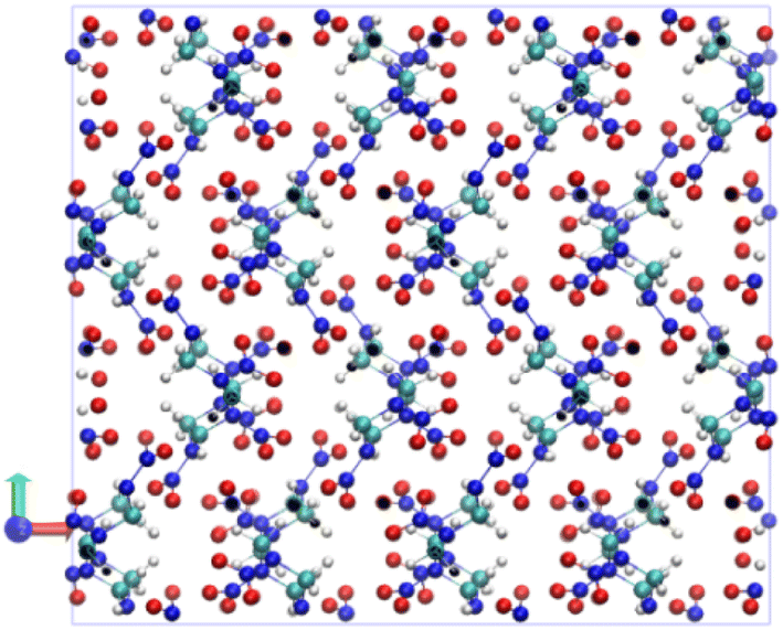
2.1.2 Model building. The RDX crystal structure was taken from X-ray diffraction results,13 and the ‘Molecular Dynamics' module of the Scigress package was applied to construct a supercell (3 × 2 × 2) based on the X-ray diffraction single crystal data. In each periodic box, there are 96 molecules, with 2016 atoms in total. The initial structure is shown in Fig. 1. The Molecular Dynamics module in the Scigress software14 was used to anneal and optimize the constructed supercell crystal. The optimized structure is effective in eliminating the unreasonable contacts present in the initial structure. The intensity of magnetic field was set to 0 T and 6 T, respectively, with the direction along the Z-axis. The Dreiding force field was used by the RDX molecules, and the intermolecular interactions of RDX were modeled using the Lennard-Jones potential. The atomic charge adopted the REPEAT charge, and the specific method used to obtain this charge was based on the CP2K first principles software using density functional theory,15 the BLYP functional, and the DZVP MOLOPT-SR-GTH basis set.16,17 Considering the D3-BJ dispersion correction,18 the structure of the RDX single crystal cell was optimized, and REPEAT charge calculations were performed on the optimized structure. To further ensure the lowest energy state of the RDX supercell system, a molecular dynamics relaxation of 150 ps was performed under the NVT ensemble, with the temperature set at 298 K and an integration step set to 1 fs. The temperature was controlled using the Velocity Rescaling algorithm. Then, a molecular dynamics relaxation of another 150 ps was performed under the NPT ensemble,19,20 with the temperature maintained at 298 K and the pressure at 1 bar. Fig. 2 shows the schematic diagram of RDX cell temperature under magnetic field. The pressure was controlled using the Parrinello-Rahman algorithm. With the final structure obtained, molecular dynamics simulations continued for 25 ps under the NPT ensemble to save one frame of conformation at an interval of 5 fs. This resulted in a total of 5000 frames of conformation for the purpose of performance calculation and analysis.
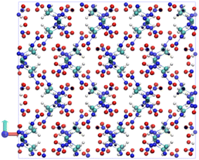 |
| | Fig. 1 Schematic diagram of the initial structure of RDX. | |
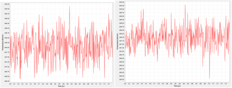 |
| | Fig. 2 Schematic diagram of RDX cell temperature under magnetic field (0Tand 6T). | |
2.2 Strong magnetic loading experiment
2.2.1 Stable strong magnetic field radiation environment loading. A stable strong magnetic field radiation environment (6T) was created using a PPMS comprehensive physical property analyzer, a completely helium-free physical property measurement system launched by QD Company. As the second measurement system introduced by QD Company, following the multifunctional vibration sample magnetometer, this PPMS comprehensive physical property analyzer does not require any refrigerants such as liquid helium. The system relies on a two-stage pulse tube cooler to create an ultra-low vibration temperature environment for the superconducting magnets and sample measurements. A stable strong magnetic field experimental platform was provided as strong magnetic fields, ultra-high pressure, and extremely low temperatures were integrated to conduct cutting-edge research in a variety of disciplines such as condensed matter physics, chemistry, materials science, biology, life sciences, and microgravity science. In this system, RDX powder energetic crystals were first subjected to high-intensity magnetic field loading, with a magnetic field intensity of up to 6T and a magnetic field radiation time of 10 hours.High-resolution optical microscopy and scanning electron microscopy were performed to characterize the morphology of the crystal samples before and after exposure to a strong magnetic field, with the evolution of their microscopic morphology observed. Confocal Raman spectroscopy was performed to characterize the crystal structure of the samples after magnetic field radiation, revealing the evolution of the crystal structure, the phase transition behavior, and the structure–activity relationship with the magnetic field. Manufactured by Zeiss in Germany, the scanning electron microscope, model ZEISS Sigma has an emission current of 4 A and an emission voltage of 30 kV. The Raman spectrometer, model HR800, is produced by HORIBA company, with a laser wavelength of 532 nm and a spectral resolution of 1 cm−1. The captured spectra were fitted using Gaussian and Lorentz functions. The X-ray powder diffractometer, model D-MAX-3C, is provided by Rigaku Company in Japan, featuring a Cu Kα X-ray source. It has a goniometer accuracy of 0.02°, a wavelength of 0.15406 nm, and a comprehensive strength stability of 0.5%. The differential scanning calorimeter, model TA Q2000, is produced by TA Company in the United States, with a temperature range of 50–400 °C and a heating rate of 10 K min−1. Produced by Netzsch Instruments in Germany, the thermogravimetric analyzer, model Netzsch STA409, has a heating rate of 10 K min−1 as well.
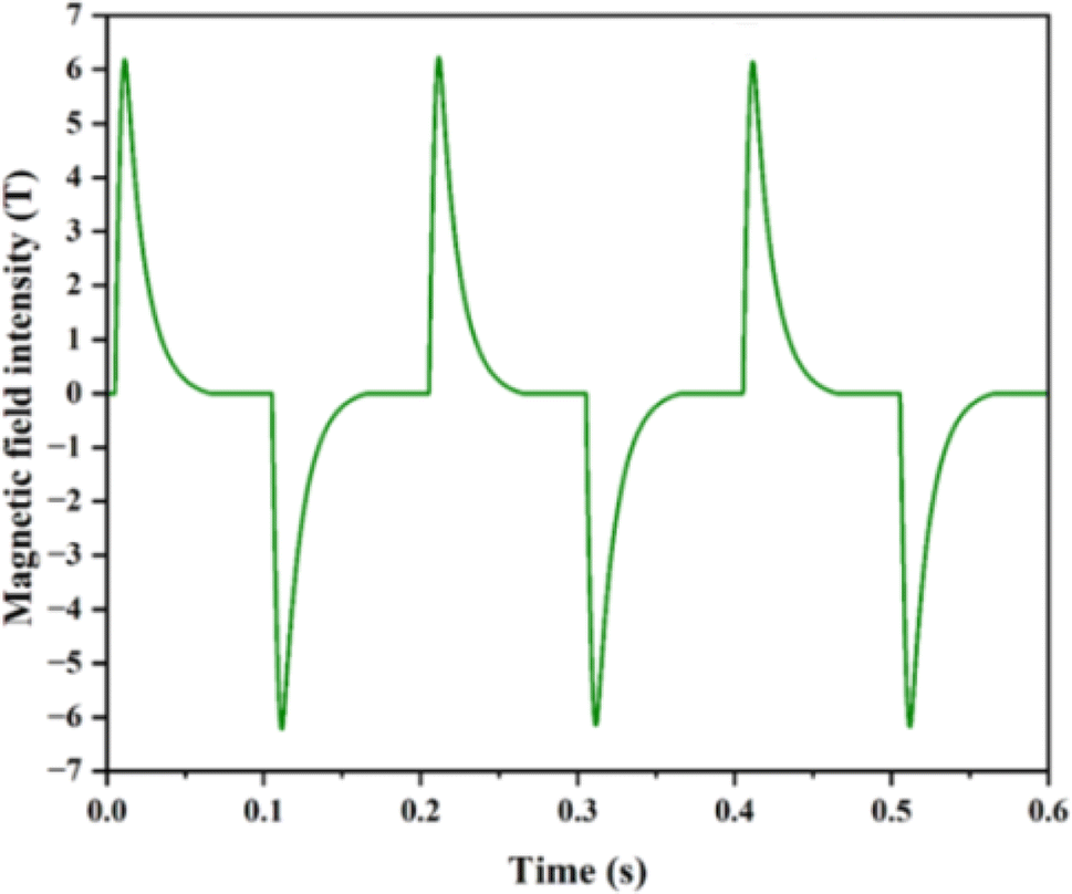
2.2.2 Alternating magnetic field radiation environment loading. The Magnetic Characteristics Science Experimental Station of the National Pulse Strong Magnetic Field Science Center was adopted to create the environment of alternating magnetic field irradiation. This experimental station consists of several components: the liquid nitrogen Dewar and sample rod part, the Dewar and magnet, the low-temperature gas processing system, and the signal acquisition system. A magnetic field with an amplitude of ±6T and a pulse width of 100 ms was applied. As illustrated in Fig. 3, positive and negative pulses were continuously applied, with the peak frequency increasing with the magnetic field variation frequency, reaching 600T s−1 at maximum.
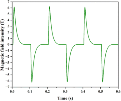 |
| | Fig. 3 Variation curve of bidirectional pulse magnetic field intensity over time. | |
2.2.3 Positron annihilation lifetime spectroscopy (PALS) testing21. The micro defects in the samples before and after strong magnetic irradiation were characterized using the positron annihilation lifetime spectrometer at the University of Science and Technology of China. Fig. 4 displays the structure of the spectrometer. To conduct test, two samples were used to clamp the radiation source, which was wrapped in two extremely thin Kapton films. By adjusting the energy window of the constant ratio timing discriminator, the two probes of the spectrometer could detect the start γ-ray (energy of 1.28 MeV) and end γ-ray (energy of 0.511 MeV) of the annihilation event, with timing signals generated. After being converted into the pulses of varying amplitudes by a time-to-amplitude converter, these signals were recorded by a multi-channel analyzer, and transmitted to a computer. The computer, using specific software, processed these signals to capture the positron annihilation lifetime spectrum.
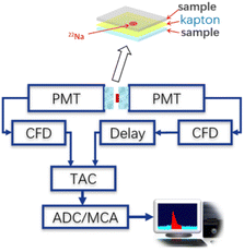 |
| | Fig. 4 Structural diagram of positron annihilation lifetime spectrometer. | |
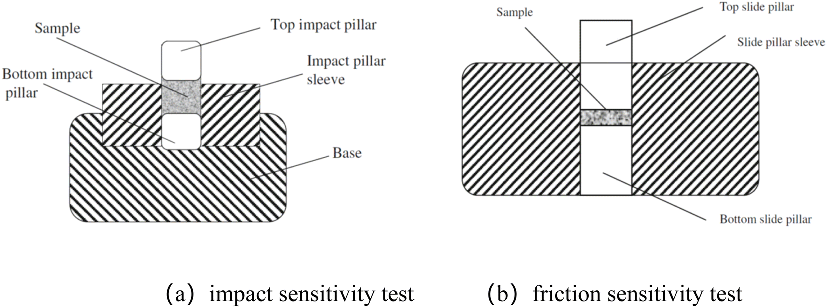
2.2.4 Sensitivity and energy test. The impact sensitivity was evaluated using the Chinese GJB772A-97 method 601.1.22,23 As illustrated in Fig. 5, the samples were positioned between two smooth hard surfaces and subjected to the impact of a drop hammer from a fixed height. The probability of explosion was determined to characterize the impact sensitivity. The hammer weighed 10 kg, and the explosive sample weighed 50 mg. The experimental devices for impact sensitivity and friction sensitivity are shown in Fig. 5(a and b), respectively. With the hammer dropped from a height of 25 cm, an explosion was indicated by sound, light, smoke, sample discoloration, marks on the impact pillar's surface, or the smell of gaseous decomposition or explosion products. No explosion occurred in the absence of these indicators. The explosive probability for a test set of 25 samples was calculated as follows:| |
 | (1) |
Here P represents the explosion probability, and X refers to the number of explosions for 25 samples.
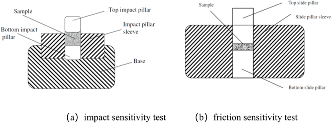 |
| | Fig. 5 Experimental device for sensitivity test. | |
Friction sensitivity was tested according to the Chinese GJB772A-97 method 602.1. Placed between two smooth hard surfaces, the samples were subjected to a constant pressure, and an external force of sliding friction. The probability of explosion was obtained to characterize the friction sensitivity. The WM-1 friction sensitivity instrument, as shown in Fig. 5, was employed. The gauge pressure was set to 3.92 MPa, and the weight of the explosive sample was 20 mg. With the swing angle set to 90°, the impact hammer of the pendulum was released, causing the top slide pillar to move a distance. An explosion was indicated by such phenomena as sound, light, smoke, sample discoloration, the traces on the surface of the impact pillar, or the smell of gaseous decomposition or explosion products. In the absence of these indicators, no explosion was deemed to have occurred. The explosive probability for a set of tests (25 samples) was calculated using eqn (1).
In order to prepare the shaped powder, a 2% mass ratio of No. 68 paraffin was used for RDX powder before and after strong magnetic field irradiation, which was then pressed into explosive columns with the dimensions of Φ25 mm × 25 g for subsequent explosion heat testing. Here, all RDX used in the paper is synthesized by Xi'an Modern Chemistry Research Institute, with a particle size between 100–200 μm. According to the method 701.1 of GJB772A-1997, the detonation heat of RDX-based explosives was tested using the adiabatic method. The explosive column, specified as Φ25 mm × 25 g, was placed in a 5.8 L explosive heat bomb. This bomb was vacuumed to −0.094 MPa, with distilled water as the medium of temperature measurement (distilled water volume of 16.5 L). The constant-volume explosive heat value of the RDX-based explosive per unit mass was calculated using the heat capacity value of the explosive heat bomb system and the rise in water temperature after detonation. The error in three consecutive explosive heat tests was not supposed to exceed 3%, and the average value of the three tests was treated as the explosive heat of the RDX-based explosive.
3 Results and discussion
3.1 Research on the response of RDX under stable magnetic field
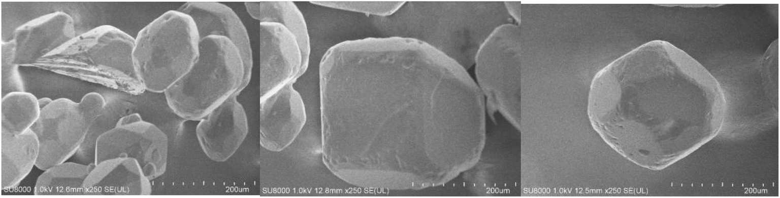
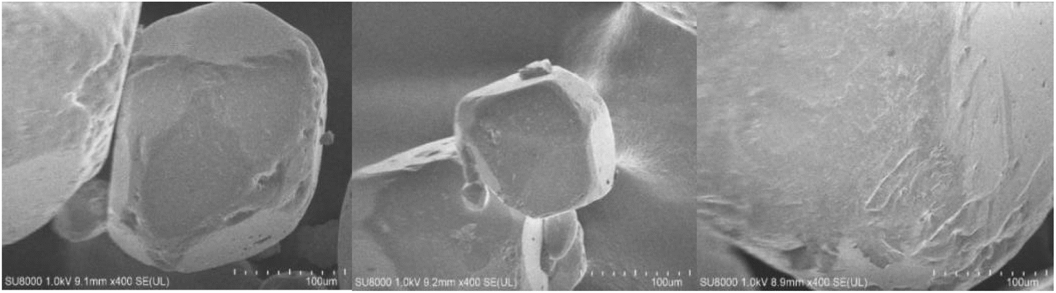
Fig. 6 presents the SEM image of RDX energetic crystal as captured prior to magnetic field irradiation. Obviously, the RDX exhibits a polyhedral morphology. Featuring a smooth surface and complete crystals, it has a size that varies from 100 to 200 μm. After 10 hours of irradiation with a high-intensity magnetic field of 6T, the crystal surface exhibited more pronounced grooves, as can be seen in Fig. 7. As revealed by comparing the SEM images before and after, the high-intensity magnetic field exerts an appreciable effect on the microstructure of the RDX crystal surface, causing either the growth or extension of cracks or grooves on the crystal surface.
 |
| | Fig. 6 SEM images of RDX crystals before magnetic field irradiation. | |
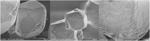 |
| | Fig. 7 SEM images of RDX crystals after magnetic field irradiation. | |
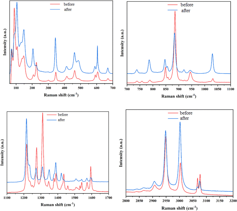
Fig. 8 presents the results of comparing the Raman spectra of RDX crystals before and after magnetic field irradiation. Evidently, the RDX exhibits the typical characteristics of the α-phase structure relative to the literature, which remains unchanged before and after irradiation. On this basis, it can be confirmed as the most stable crystal structure at room temperature and pressure. However, judging from the details, there are significant changes in the relative intensity of Raman vibration modes between molecules, the respiratory vibration of rings, CH2 shear vibration, and C–H stretching vibration modes at low wavenumbers, specifically around 200, 600, 1450, and 3080 cm−1. Induced by magnetic field irradiation, the stress may affect the relative intensity of the Raman peaks.
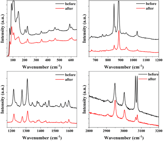 |
| | Fig. 8 Comparison of Raman spectra of RDX crystals before and after 6T stable magnetic field irradiation. | |
3.2 Research on the response of RDX under alternating magnetic field
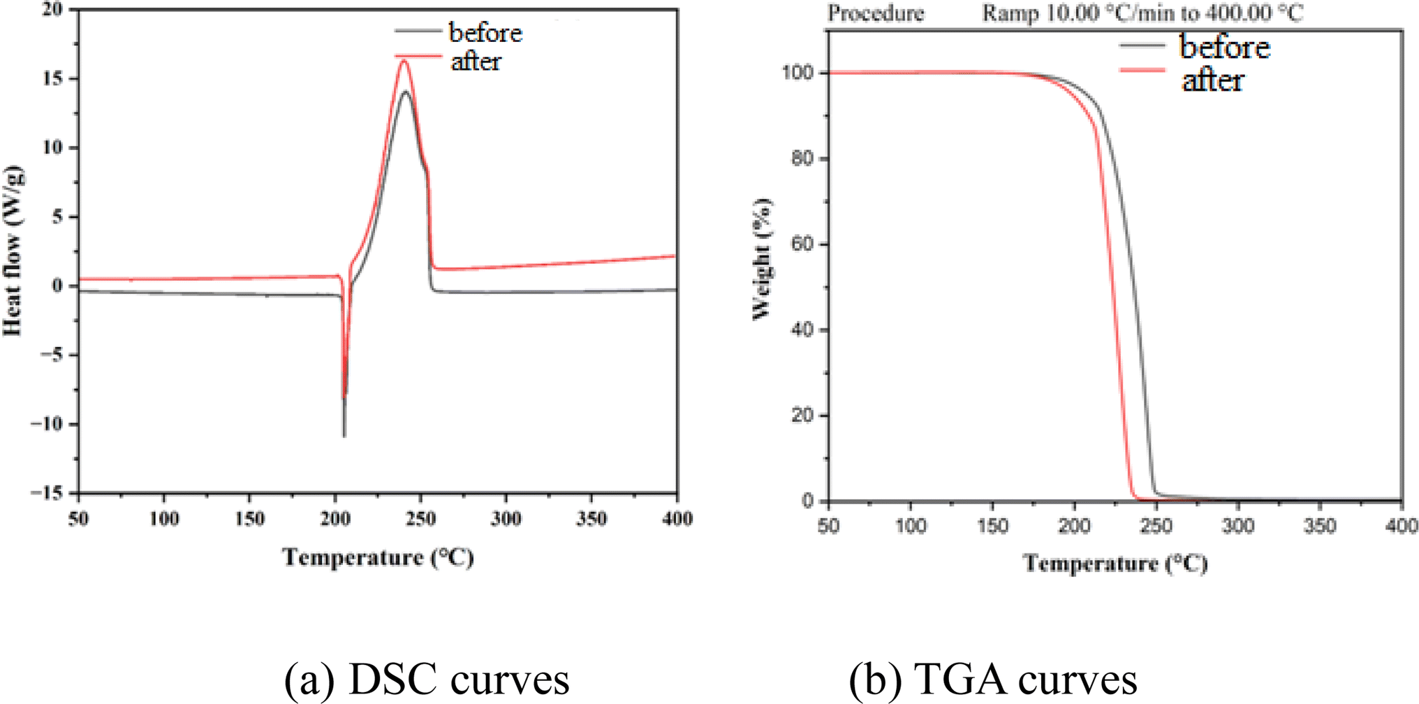
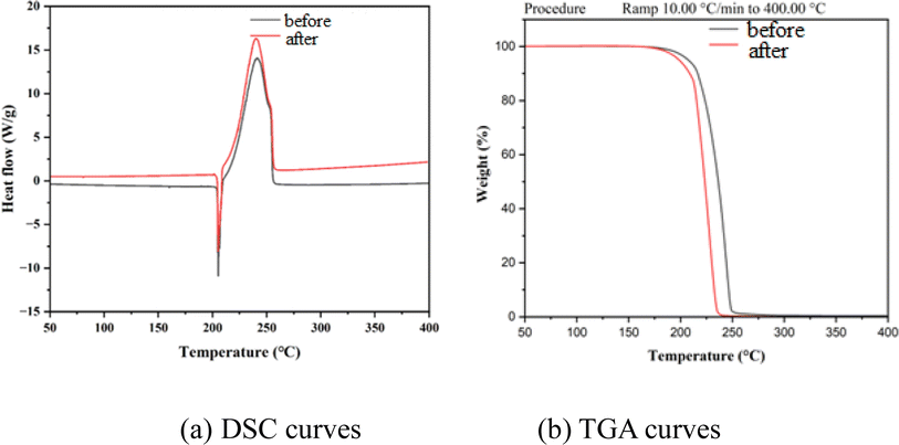
Fig. 9 shows the SEM image of the energetic crystal RDX after irradiation with a ±6T alternating magnetic field. In comparison with the results of the 6T stable magnetic field, the crystal surface exhibits various evident grooves and pores, presenting a fish-scale-like structure. This indicates a greater likelihood for the alternating magnetic field to peel off small particles on the surface and to induce surface dislocations by stimulating greater strain. As shown in Fig. 10, significant changes are observable in the Raman spectra before and after irradiation with alternating magnetic fields at different wavenumber positions. There are such prominent changes as the shift of Raman peaks at low wavenumbers (below 200 cm−1), the variations in the relative intensity of Raman vibration modes at 600, 950, 1380, and 3070 cm−1, and the emergence of new Raman vibration modes after magnetic field irradiation at 1600 cm−1, which split from the original single peak to a double peak. These obvious changes in peak intensity reaffirm the strong strain generated by the alternating magnetic field on the sample. Fig. 11(a and b) show the DSC and TGA curves of RDX crystals before and after irradiation with a ±6T alternating magnetic field, at a heating rate of 10 °C min−1, respectively. According to the research results, magnetic field irradiation barely affects the thermal decomposition process of RDX crystals, and the decomposition heat release invariably peaks at around 240 °C. Thermal decomposition is closely associated with intermolecular and intramolecular hydrogen bonding. As indicated by Raman spectroscopy, there is no significant shift exhibited by the vibration peaks related to hydrogen bonding, which substantiates the conclusion that the decomposition temperature is stable.
 |
| | Fig. 9 SEM images of RDX crystals irradiated with ±6T alternating magnetic field. | |
 |
| | Fig. 10 Comparison of Raman spectra of RDX crystals before and after irradiation with ±6T alternating magnetic field. | |
 |
| | Fig. 11 Thermal performance curves of RDX crystals before and after irradiation with ±6T alternating magnetic field. | |
In summary, magnetic field irradiation can affect the surface morphology of RDX crystal samples. Despite generating greater strain within the crystal, alternating magnetic fields have a less significant impact on it in terms of crystal structure and thermal decomposition properties.
3.3 Positron annihilation lifetime spectroscopy (PALS) testing
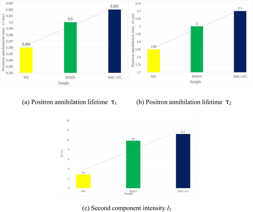
Due to the unique sensitivity of positrons to atomic-scale microstructures, they are considered applicable as an indispensable probe for the study of material defects. Currently, positron annihilation spectroscopy has been recognized as a practical and mature experimental method for the study of material defects and phase transitions, which provides various microscopic information such as vacancy-type defects, dislocations, and electron momentum distribution inside various materials, including metals and semiconductors. There are three mainstream experimental methods suitable for positron annihilation spectroscopy: positron lifetime, Doppler broadening of annihilation radiation, and angle correlation of annihilation radiation.24–26 Among them, positron lifetime measurement represents the most widely used technique, providing the most microstructural information. The positron lifetime is routinely measured using a time coincidence spectrometer in nuclear physics experiments, so as to determine the interval between the emission and annihilation of positrons. Regarding positron annihilation experiments, the commonly used method is the fast–fast coincidence positron lifetime spectrometer. As for positron annihilation spectroscopy, the accuracy of its measurement of positron lifetime is critical. By analyzing the lifetime spectrum through the PATFIT program, the presence of lifetime components in RDX was discovered. Among them, τ1 is believed to originate from the annihilation of free-state positrons and p-Ps self-annihilation, and τ2 results from the annihilation of positrons in defects and pores. For the samples of RDX series, the first lifetime component (τ1) is associated with the annihilation resulting from various small-sized defects such as bulk annihilation and single vacancies, while the second lifetime component (τ2) is related to the annihilation within sub-nanometer-sized pores (with a diameter of approximately 0.4–0.5 nm) within or between grains.
Fig. 12(a–c) show the test results that indicate the first component lifetime (τ1), the second component lifetime (τ2) and second component intensity (I2) of the samples before and after magnetic field treatment, respectively. Compared to the RDX before magnetic field treatment, there is a slight increase found in τ1 and τ2 of RDX following magnetic field treatment. We decompose the positron annihilation spectrum of RDX to obtain the normalized intensity I2 corresponding to the second lifetime component (τ2). Most notably, a significant increase is shown by the second component intensity I2 of the RDX(6T) and RDX (±6T) sample, which suggests a significant increase in the number of pores in the RDX samples after the treatment with a 6T stable magnetic field and ±6T alternating magnetic field. Further analysis revealed the number of pores in the RDX samples treated with a ±6T magnetic alternating field relative to the RDX samples treated with a 6T stable magnetic field.
 |
| | Fig. 12 Positron annihilation lifetime spectroscopy (PALS) testing results. | |
3.4 Sensitivity and explosive heat
According to the previous research results, strong magnetic radiation, particularly under ±6T alternating magnetic field conditions, can lead to a significant change in the microstructure and Raman spectrum of RDX crystals. Therefore, an investigation was conducted into the sensitivity of RDX crystals under a ±6T alternating magnetic field and the variation pattern of 98% RDX-based mixed explosives.
Fig. 13 shows the changes in sensitivity of RDX crystals tested before and after irradiation with a ±6T alternating magnetic field. The results indicate that the sensitivity of RDX crystals can be significantly reduced by the ±6T alternating magnetic field. Statistically, the impact sensitivity decreases from 76% to 60%, down 21.0%. Meanwhile, the friction sensitivity declines from 72% to 48%, down 33.3%. As indicated by the test results of the microstructure, the irradiation with a ±6T alternating magnetic field increases the number of defects on the surface of RDX crystals, which may improve sensitivity and undermine the safety of RDX. Therefore, the significant decrease caused by the ±6T alternating magnetic field in the sensitivity of RDX crystals is attributed not to the changes in microstructure but to the impact of the field on the crystal structure of RDX. This effect can enhance the stability of the RDX crystal structure, reducing sensitivity. For further research, more in-depth molecular dynamics calculations will be conducted.
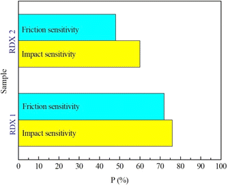 |
| | Fig. 13 Sensitivities of two RDX samples. RDX 1 and RDX 2 correspond to the crystals before and after irradiation with ±6T alternating magnetic field. | |
A test was conducted on the detonation heat of RDX-based mixed explosives with a 98% content before and after irradiation with a ±6T alternating magnetic field. The detonation heat of the RDX-based explosives before and after strong magnetic irradiation was 5403 J g−1 and 5395 J g−1, respectively, both of which fall within the error range of the explosion heat test. It is indicated that strong magnetic irradiation makes little difference to RDX in terms of chemical structure and energy release level.
3.5 Research on the response mechanism of RDX under strong magnetic effects
The lattice constant changes of RDX under different magnetic fields were calculated, with the calculation results presented in Table 2. As can be seen in the table, the magnetic field exerts no significant effect on the lattice constants of the energetic materials.
Table 2 Lattice constants after optimizing RDX structure under different magnetic fields
| Sample |
Lattice parameters |
0T |
6T |
| RDX |
a (Å) |
26.538 |
26.538 |
| b (Å) |
23.369 |
23.369 |
| c (Å) |
32.121 |
32.121 |
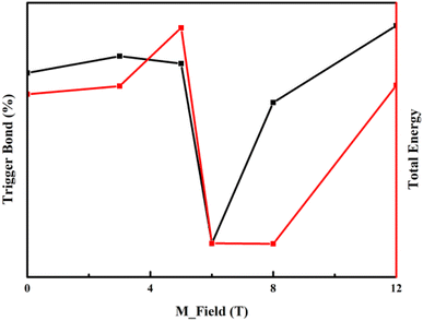
The ‘Minimum Bond Order Principle’ (PSBO) was discovered based on quantum chemical calculations earlier. For the explosives similar in series structure or pyrolysis mechanism, a smaller initiating bond order leads to a lower structural stability. During the establishment of reactivity sites, a functional relationship between energy and bond order is also established according to the bond order.27–29 As shown in Fig. 14, when N–NO2 triggers the stability of bond length-related structures, the most probable bond length (Lprop) and average bond length (Lave) of the four structures are found to barely vary with temperature rise. The maximum bond length (Lmax) monotonically increases to a significant extent as the temperature rises. These molecules are vitally important, despite comprising a small proportion in the probability distribution of bond lengths. Thus, the bond length is presumed to increase with temperature rise. A very small number of molecules with the maximum bond length are “activated,” which easily leads to decomposition and detonation. Consequently, the structural stability of explosives declines. As a crucial property of energetic materials, sensitivity determines their usability. As shown in the figure above, the total energy of RDX is the highest when the magnetic field is 5T, and the total energy of RDX is the lowest when the magnetic field value is 6T. From the perspective of initiating bonds, the proportion of the longest initiating bonds in RDX crystals is the lowest when the magnetic field is 6T, which corresponds to the lowest total energy of RDX. In summary, the molecular dynamics results indicate that the RDX crystal structure is more stable at 6T than in the absence of magnetic field, which is consistent with the results of sensitivity test.
 |
| | Fig. 14 Schematic diagram of the proportion of longest triggered bonds in RDX under different magnetic fields. | |
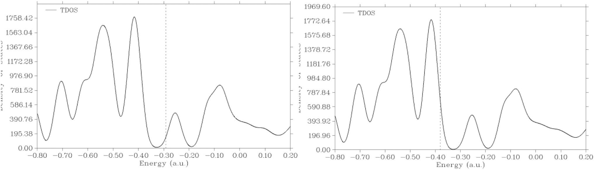
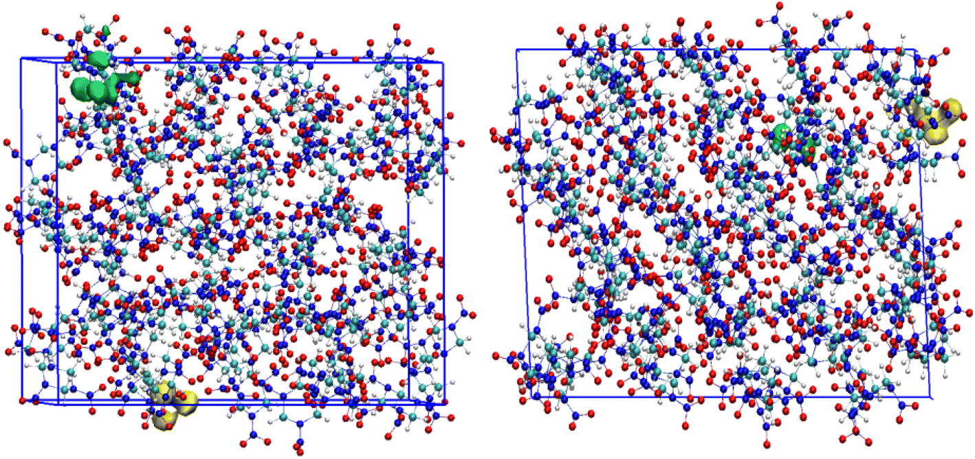
As a function with energy as the variable, the density of states represents the number of states per unit energy interval at a certain energy level. According to the Fig. 15, 16 and Table 3, the peak values have changed, despite no significant changes in the peak shape of the density of states in RDX crystals under different magnetic fields. As inferred from the highest occupied and lowest unoccupied molecular orbitals of RDX under different magnetic fields, there are changes with the magnetic field as well in the positions of the highest occupied and lowest unoccupied orbitals of RDX. Reflecting the numerical value of the transition of atoms within a crystal from the highest occupied orbital to the lowest unoccupied orbital, the crystal energy gap is closely related to the chemical activity of the crystal. As shown in the table above, the crystal energy gap of RDX is significantly larger than that of RDX without a magnetic field when the magnetic field value is 6T, indicating the inhibitory effect of a strong magnetic field on the crystal energy gap of RDX.
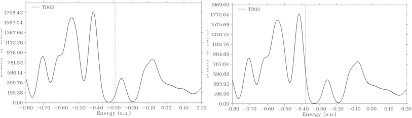 |
| | Fig. 15 Schematic diagram of RDX density of states under magnetic fields (0T, 3T, 5T, 6T, 8T, and 12T), with vertical lines representing HOMO energy. | |
 |
| | Fig. 16 Schematic diagram of HOMO (green) and LUMO (yellow) of RDX under magnetic fields (0T and 6T). | |
Table 3 Orbital energy and energy bands of RDX under different magnetic fields
| M_field (T) |
HOMO (eV) |
LUMO (eV) |
Gap (eV) |
| 0 |
−7.95333 |
−7.71017 |
0.24316 |
| 6 |
−10.34956 |
−8.07613 |
2.27332 |
4 Conclusions
(1) A stable magnetic field (6T for 10 hours) affects the microstructure of the RDX crystal surface, inducing the growth or extension of cracks or grooves on the crystal surface.
(2) Compared with the stable magnetic field of 6T, the alternating magnetic field of ±6T is more likely to peel off small particles from the surface and to induce surface dislocations by stimulating greater strain. Furthermore, a ±6T alternating magnetic field is capable to significantly reduce the sensitivity of RDX crystals. However, the strong magnetic field has no effect on the phase, the lattice constants and the thermal decomposition performance of RDX.
(3) According to the results of molecular dynamics simulation, a 6T field strength is effective in significantly reducing the maximum length and number of initiation bond inside the RDX crystal, which is conducive to reducing the sensitivity of RDX.
Data availability
The data supporting the findings of this study are currently stored on a personal computer. Due to data protection, they are not available in a public repository. However, the data may be accessed upon reasonable request. Contact Jun Tao via email E-mail: totaojun4712230@126.com.
Author contributions
Jun Tao contributed to the design of the study, performed statistical analyses, and drafted the manuscript. Haichao Ren contributed to the data collection, interpretation, and provided critical feedback on the manuscript. Yufan Bu contributed to the study design, data analysis, and revised the manuscript.
Conflicts of interest
There are no conflicts or competing interests to declare.
Acknowledgements
Grateful acknowledgement is made to professor Xiaofeng Wang who gave me considerable help by means of suggestion, comments and criticism. His encouragement and unwavering support has sustained me through frustration and depression. Without his pushing me ahead, the completion of this thesis would be impossible. In addition, I deeply appreciate the contribution to this thesis made in various ways by my colleagues.
References
- H. D. Fair, Progress in electromagnetic launch science and technology, IEEE Trans. Magn., 2007, 43(1), 93–98 Search PubMed.
- H. D. Fair, Guest editorial the past, present, and future of electromagnetic launch technology and the IEEE international EML symposia, IEEE Trans. Plasma Sci., 2015, 43(5), 1112–1116 Search PubMed.
- U. S. Navy, Navy rail gun test Dalgren, VA. 2006 & 2008 [EB/OI]. [2016-04-01], http://www.Eugenelesslover.com/VIDEOS/Rail_Gun.html.
- G. Fein, Navy sets new world record with electromagnetic railgun demonstration [EB/OI]. 2016-04-01, http://www.Navy.mil/submit/display.asp?story_id=57690.
- H. D. Fair, Progress in Electromagnetic Launch Science and Technology, 2007, pp. 93–98 Search PubMed.
- A. N. Smith, R. L. ELLIS, J. S. BERNARDES, et al., Thermal Management and Resistive Rail Heating of a Large-Scale Naval Electromagnetic Launcher, 2005, 235–240 Search PubMed.
- H. D. Fair, Electromagnetic Launch Science and Technology in the United States Enters a New Era, 2005, pp. 158–164 Search PubMed.
- T. R. Lockner, R. J. Kaye and B. N. Turman, Coilgun technology, status, applications, and future directions at Sandia National Laboratories, 2004 IEEE International Power Modulator Conference: 26th International Power Modulator Symposium and 2004 High Voltage Workshop, May 23, 2004 - May 26, 2004, San Francisco, CA,United states, 2004, pp. 119–121 Search PubMed.
- L. Guo, S. Wang and N. Guo, et al., Simulation and Optimization of Six-Stage Electromagnetic Coilgun, Int. J. Appl. Electromagn. Mech., 2010, 33(1), 465–471 CrossRef.
- D. G. Tasker, V. H. Whitley and R. J. Lee, Electromagnetic Field Effects in Explosives [C], AIP Conf. Proc., 2009, 1195, 335–338 CrossRef CAS.
- J. F. Jin, J. Ma, H. Z. Yao, et al., The Study on the Characters of DHL Explosives Rade by Electromagnetic radiation[C]//Chinese Mechanical Conference, Chinese Mechanics Academic Society, Beijing, 2019, pp. 1673–1679 Search PubMed.
- S. L. Mayo, B. O. Olafson and W. A. Goddard, Dreiding: a generic force field for molecular simulations, J. Phys. Chem., 1990, 94(26), 8897–8909 CrossRef CAS.
- R. M. Vrcelj, J. N. Sherwood and A. R. Kennedy, et al., Polymorphism in 2-4-6 Trinitrotoluene, Cryst. Growth Des., 2003, 3(6), 1027–1032 CrossRef CAS.
- I. G. Marchenko and I. L. Marchenko, Applications of molecular simulation software SCIGRESS in industry and university, 18th International Summer School on Vacuum, Electron and Ion Technologies, VEIT, 2013 Search PubMed.
- T. S. Kühne, M. Lannuzzi and M. D. Ben, et al., CP2K: An electronic and structure and molecular dynamic software package- Quickstep: efficient and accurate electronic structure calculations, J. Chem. Phys., 2020, 152, 194103 CrossRef.
- A. D. Becke, Density-Function Exchange Approximation with Correct Asymptotic Behavior, Phys. Rev. A, 1988, 38, 3098 CrossRef CAS.
- C. Lee, W. Yang and R. G. Parr, Development of the Colle-salvetti Correlation-energy Formula into a Functional of the Electron Density, Phys. Rev. B, 1988, 37, 785–789 CrossRef CAS PubMed.
- S. Goedecker, M. Teter and J. Hutter, Separable dual-space Gaussian pseudopotentials, Phys. Rev. B, 1996, 54(3), 1703–1710 CrossRef CAS PubMed.
- J. Tao, X. F. Wang and H. Wang, et al., Multiscale design, interaction mechanism and performance of CL-20/Al energetic composites with embedded structure, RSC Adv., 2020, 10, 44846–44853 RSC.
- J. Tao and X. F. Wang, Crystalline behaviors of HMX-Al composites in solvents: Amolecular dynamics and experimental study, J. Mater. Res., 2019, 34(5), 867–875 CrossRef CAS.
- J. M. Li, Y. Tian and X. P. Hao, et al., Effect of heat treatment on the microstructure of TATB based PBX by PALS, Energetic Mater., 2005, 13(6), 378–381 CAS.
- B. Jin, J. Shen and R. F. Peng, et al., Synthesis, characterization, thermal stability and mechanical sensitivity of polyvinyl azidoacetate as a new energetic binder, J. Polym. Res., 2012, 19(10), 9974–9978 CrossRef.
- J. Tao and X. F. Wang, Crystal structure
and morphology of β-HMX in acetone: A molecular dynamics simulation and experimental study, J. Chem. Sci., 2017, 129, 495–503 CrossRef CAS.
- K. Ito, T. Oka and Y. Kobayashi, et al., Interlaboratory comparison of positron annihilation lifetime measurements for synthetic fused silica and polycarbonate, J. Appl. Phys., 2008, 104, 02 CrossRef.
- Q. C. Zhi, T. Suzuki and K. Kondo, et al., Free volume in polycarbonate studied by positron annihilation: effects of free radicals and trapped electrons on positronium formation, Jpn. J. Appl. Phys., 2001, 40(Part1), 5036–5040 Search PubMed.
- P. Kirkegaard, N. J. Pederson and M. Eldrup, PATFIT-88: a Date-Processing System for Positron Annihilation Spectra on Mainframe and Personal Computers, Risφ National Laboratory, Roskilde, Denmark, 1989 Search PubMed.
- J. J. Xiao, W. R. Wang and J. Chen, et al., Study on the relations of sensitivity with energy properties for HMX and HMX-based PBXs by molecular dynamics simulation, Physica B, 2012, 407(17), 3504–3509 CrossRef CAS.
- J. J. Xiao, S. Y. Li and J. Chen, et al., Molecular dynamics study on the correlation between structure and sensitivity for defective RDX crystals and their PBXs, J. Mol. Model., 2013, 19(2), 803–809 CrossRef CAS PubMed.
- L. Zhao, J. J. Xiao and J. Chen, et al., Molecular dynamics study on the relationships of modeling, structural structure and energy properties with sensitivity for RDX-based PBXs, Sci. Sin. Chim., 2013, 43(5), 576–584 CrossRef CAS.
|
| This journal is © The Royal Society of Chemistry 2025 |
Click here to see how this site uses Cookies. View our privacy policy here. 
 Open Access Article
 This Open Access Article is licensed under a Creative Commons Attribution-Non Commercial 3.0 Unported Licence
 *,
Haichao Ren and
Yufan Bu
*,
Haichao Ren and
Yufan Bu