 Open Access Article
Tuning surface hydrophilicity of a BiVO4 photoanode through interface engineering for efficient PEC water splitting†
Shuangwei Yu,
Chunrong Su,
Zhehui Xiao,
Yi Kuang,
Xue Gong,
Xiong He*,
Jinghua Liu*,
Qianqian Jin and
Zijun Sun *
*
School of Electronic Engineering, Guangxi Key Laboratory of Multidimensional Information Fusion for Intelligent Vehicles, Guangxi University of Science and Technology, Liuzhou 545000, China. E-mail: hexiong@gxust.edu.cn; liujinghua@gxust.edu.cn; sunzijun@gxust.edu.cn
First published on 10th January 2025
Abstract
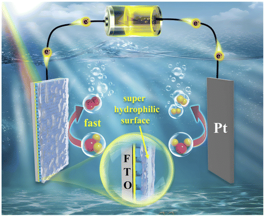
This study presents a novel approach to enhance photoelectrochemical (PEC) water oxidation by integrating cobalt phthalocyanine (CoPc) with bismuth vanadate (BVO) via a direct solvothermal method. The as-prepared BVO@CoPc photoanode demonstrated a photocurrent density of 4.0 mA cm−2 at 1.23 V vs. RHE, which is approximately 3.1 times greater than that of the unmodified BVO, and has superior stability. The incident photon-to-current conversion efficiency (IPCE) of the BVO@CoPc photoanode reaches an impressive value of 81%, accompanied by significant enhancements in charge injection efficiency. This excellent performance can be ascribed to the enhanced hydrophilicity with the BVO/CoPc interface engineering, which facilitates interfacial interaction between the electrode and electrolyte, accelerates photogenerated charge carrier transfer and separation. Furthermore, compared to the immersion and drop-casting methods, the BVO@CoPc-S composite photoanode prepared via the solvothermal method exhibits a significant improvement in interfacial contact and surface hydrophilicity. These findings highlight the potential of the strategy based on interfacial hydrophilicity modification to overcome key limitations in PEC water splitting, providing a pathway to more efficient and durable photoanode design.
1. Introduction
With the rising demand for renewable energy sources and environmental concerns, photoelectrochemical (PEC) water splitting has gained prominence as a promising technology for converting solar energy into clean hydrogen fuel.1–3 PEC water splitting is divided into the hydrogen evolution reaction (HER) and the oxygen evolution reaction (OER).4,5 Among these, OER is the rate-limiting step due to its complex four-electron transfer process. Consequently, the exploration and design of efficient photoanode materials with the facilitated kinetics of water oxidation is critical for PEC water-splitting systems.6,7 Bismuth vanadate (BVO) has gained attention as a potential photoanode material because of its appropriate bandgap, stability under alkaline conditions, and relatively low cost. However, it is still restricted by poor charge separation efficiency and slow surface reaction kinetics.8–11A widely adopted strategy to improve the PEC performance of BVO is the integration of transition metal-based co-catalysts into the BVO photoanode. This approach effectively reduces the reaction energy barrier for water oxidation while simultaneously enhancing the reaction kinetics.12–15 For example, Sun and co-workers discovered that Co doping successfully introduced oxygen vacancies into BVO as catalytically active sites, improving overall water-splitting activity.16 Liu et al. constructed an S-type heterojunction (S-BiVO4/WO3), in which the internal electric field formed at the interface can induce a stepwise charge transfer mechanism, ultimately enhancing the water oxidation ability.17 However, the slow water oxidation kinetics at the photoanode–electrolyte interface remain a key issue hindering further improvement of the PEC water splitting performance.
In this situation, molecular catalysts have emerged as promising materials for oxygen evolution catalysis (OEC) due to their well-defined active sites, which allow precise control over catalytic activity and selectivity. Their inherently high activity, originating from metal centers and ligands, combined with highly tunable molecular structures, renders them highly attractive for broader applications.18 Among them, metal phthalocyanine (MPc)-based complexes can be synthesized and deposited on the surface of BVO to enhance PEC water splitting performance. As an example, Sun's group demonstrated that BVO/CoPc hybrid photoanodes, prepared via drop-coating, achieved a photocurrent density of 3.23 mA cm−2 at 1.23 V vs. RHE.19 As well, Shen et al. developed BiVO4 thin films loaded with cobalt phthalocyanine (CoPc(NH2)4/BiVO4), achieving a photocurrent density of 3.02 mA cm−2 under irradiation, attributed to the synergistic interaction between CoPc(NH2)4 and BiVO4.20 In similar studies, Zhao et al. employed a dipping method to co-assemble CuPc and FeOOH onto a BiVO4 photoanode, achieving a photocurrent density of 3.67 mA cm−2 at 1.23 V vs. RHE.21 The above discussion collectively highlight the effectiveness of BiVO4/phthalocyanine complexes in significantly enhancing the PEC water splitting performance.
However, in these studies, the influence of interface contact between photoanode and electrolyte on water oxidation efficiency is rarely reported, the composite photoanode prepared with hydrophobic BiVO4 and hydrophilic CoPc exhibited poor interfacial matching with the electrolyte. To accelerate water splitting, it is essential to rationally regulate hydrophilicity of the photoanode surface to improve the interfacial compatibility between the electrode and electrolyte. Recent researches have declared the interface engineering strategies with tuned hydrophilicity for enhanced PEC performance.22,23 For instance, Wang's team enhanced the PEC performance of TiO2 photoelectrode materials by improving interface properties through molecular monolayer modification. This chemical monolayer modification can change its wettability state, further inhibiting the recombination of electrons and holes.24 Yue et al. adopted a convenient strategy to prepare super-hydrophilic H-CoAl-LDH/BiVO4 composite photoanodes. The good surface wettability enables rapid adsorption of water molecules on plasma-engineered photoanodes with abundant active sites, achieving a photocurrent density of 3.5 mA cm−2 at 1.23 V vs. RHE, greatly boosting PEC water oxidation activity.25 These findings underscore that hydrophilicity-based interfacial engineering is expected to further accelerate surface water oxidation reactions as a universal strategy.26,27
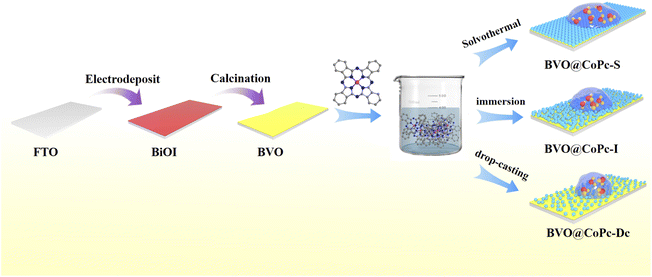
In this study, CoPc was introduced onto BVO electrode using three methods: solvothermal method (BVO@CoPc-S), impregnation method (BVO@CoPc-I), and drop coating method (BVO@CoPc-Dc), as shown in Scheme 1. The BVO@CoPc-S photoanode exhibited high surface hydrophilic properties and reached a photocurrent density of 4.0 mA cm−2 at 1.23 V vs. RHE, outperforming the BVO@CoPc-Dc and BVO@CoPc-I photoanodes at 1.43 and 1.38 times, respectively, and its stability was further reinforced. This enhancement is attributed to the BVO@CoPc-S's super-hydrophilic surface, which allows the electrolyte to penetrate the surface of the photoanode, increasing the effective contact area between the electrolyte and photoanode. Comprehensive physical characterization and kinetic tests revealed that surface wettability of the photoanode is a key to enhancing both the efficiency and stability of PEC water splitting.
2. Results and discussion
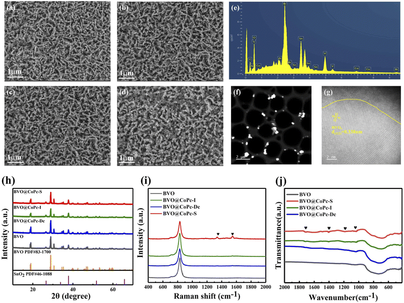
The BVO photoanode was fabricated according to a modified two-step process based on previously reported methods.28 Then BVO@CoPc-S, BVO@CoPc-I, and BVO@CoPc-Dc were fabricated with different CoPc incorporation methods. Detailed preparation procedures for BVO@CoPc-S, BVO@CoPc-I, and BVO@CoPc-Dc photoanodes are provided in the ESI.† The morphology of these synthesized photoanodes (BVO, BVO@CoPc-Dc, BVO@CoPc-I, BVO@CoPc-S) were conducted using SEM. As illustrated in Fig. 1a, pure BVO presents a 3D worm-like structure, which facilitates electrolyte diffusion.29 No significant morphological changes can be observed for BVO@CoPc-Dc, BVO@CoPc-I, and BVO@CoPc-S photoanodes as shown in Fig. 1b–d. Fig. 1e displays the energy dispersive X-ray (EDS) spectra of BVO@CoPc-S, indicating the presence of elements Bi, V, O, C, Co, and N. The Pt and Sn elements come from evaporation during the measurement and FTO glass, respectively. Transmission electron microscopy (TEM) and high-resolution transmission electron microscopy (HRTEM) images of the synthesized BVO@CoPc-S photoanodes are shown in Fig. 1f and g. The lattice spacing of 0.338 nm corresponding to the (112) plane of monoclinic BVO is observed in Fig. 1g.30 In addition, there is a uniformly distributed amorphous layer, which is probably loaded with CoPc, tightly wrapped around the surface of BVO.31 The high-quality interface between CoPc and BVO is anticipated to enhance charge transfer and boost PEC activity.The XRD patterns of BVO, BVO@CoPc-Dc, BVO@CoPc-I and BVO@CoPc-S were shown in Fig. 1h. The characteristic diffraction peaks of these prepared photoanodes closely match those of monoclinic BVO (PDF#83-1700) and SnO2 (PDF#46-1088), which confirms the successful synthesis of monoclinic BVO on fluorine-doped tin oxide substrates. However, no characteristic diffraction peaks corresponding to CoPc can be observed. The high dispersion or low loading of CoPc may be responsible for this phenomenon.32 Fig. 1i exhibits the Raman spectra of these synthesized photoanodes. A distinct characteristic peak at 826 cm−1, corresponding to V–O bonds BVO, can be detected. With CoPc incorporated in BVO, C–C stretching vibrational bands of the pyrrole group at 1138 cm−1 as well as C–N stretching vibrational bands of isoindoles at 1545 cm−1 were found.33,34 This result proves the successful introduction of CoPc in BVO. Meanwhile, the intensity of these characteristic peaks is enhanced for BVO@CoPc-S. It suggests that the good integration of CoPc onto the BVO surface with the solvothermal method.
To further evaluate the CoPc decoration under different loading strategies, the FTIR spectra of these photoanodes were conducted as shown in Fig. 1j. An obvious absorption peak at 730 cm−1, associated with V–O vibrations, can be observed. For BVO@CoPc-Dc, BVO@CoPc-I, and BVO@CoPc-S, new absorption peaks located around 1415 cm−1, 1170 cm−1, 1038 cm−1, and 1720 cm−1 can be detected, which are attributed to the vibrations of the metal–ligand and phthalocyanine backbone, C![[double bond, length as m-dash]](https://www.rsc.org/images/entities/char_e001.gif) C bonding of the benzene ring in CoPc, and stretching vibration of the Pc ring, respectively.35,36 Among these BVO@CoPc photoanodes, the BVO@CoPc-S photoanode exhibits the stronger intensity of these absorption peaks. Notably, for the BVO@CoPc-S photoanode, a slight blue shift of the V–O bond can be captured compared with pure BVO photoanode. These phenomena further indicate the successful synthesis of the BVO@CoPc-S photoanode as well as the strong chemical interactions between BVO and CoPc.37 To further investigate the optical properties of these photoanodes, UV-Vis absorption spectra were conducted as shown in Fig. S1.† In agreement with previous reports, the absorption edge of bare BVO was observed at 515 nm.38 No obvious change can be observed for the absorption edge of these BVO@CoPc photoanodes. Meanwhile, two Q bands originated from CoPc appear at 605 and 690 nm, indicating the successful synthesis of BVO@CoPc photoanodes.39
C bonding of the benzene ring in CoPc, and stretching vibration of the Pc ring, respectively.35,36 Among these BVO@CoPc photoanodes, the BVO@CoPc-S photoanode exhibits the stronger intensity of these absorption peaks. Notably, for the BVO@CoPc-S photoanode, a slight blue shift of the V–O bond can be captured compared with pure BVO photoanode. These phenomena further indicate the successful synthesis of the BVO@CoPc-S photoanode as well as the strong chemical interactions between BVO and CoPc.37 To further investigate the optical properties of these photoanodes, UV-Vis absorption spectra were conducted as shown in Fig. S1.† In agreement with previous reports, the absorption edge of bare BVO was observed at 515 nm.38 No obvious change can be observed for the absorption edge of these BVO@CoPc photoanodes. Meanwhile, two Q bands originated from CoPc appear at 605 and 690 nm, indicating the successful synthesis of BVO@CoPc photoanodes.39
X-ray photoelectron spectroscopy (XPS) was utilized to investigate the surface valence states and chemical composition of these photoanodes. The V 2p, Bi 4f, O 1s, N 1s, C 1s, and Co 2p XPS spectra are shown in Fig. 2. The V 2p XPS spectra (Fig. 2a) demonstrate the peaks located at 516.7 and 524.3 eV, corresponding to V5+ 2p3/2 and V5+ 2p1/2, respectively. Peaks at 159.0 and 164.3 eV, assigned to Bi3+ 4f 7/2 and Bi3+ 4f 5/2, respectively, are seen in the Bi 4f spectra (Fig. 2b). It should be noted that the Bi 4f and V 2p XPS spectra of BVO, BVO@CoPc-Dc, and BVO@CoPc-I are similar, but a slight shift towards higher binding energy can be observed for Bi 4f and V 2p XPS spectra of BVO@CoPc-S. The Bi 4f7/2 and Bi 4f5/2 peaks are positively shifted to 159.3 and 164.6 eV, respectively. The peaks of V 2p1/2 and V 2p3/2 are shifted to 524.5 and 516.9 eV, respectively, indicating the strong chemical interaction between BVO and CoPc in BVO@CoPc-S.20 This result is consistent with the findings from the FTIR analysis. For O 1s spectra (Fig. 2c), two distinct peaks are visible at 529.8 and 531.6 eV, corresponding to the lattice oxygen (OL) and adsorbed oxygen (OAd), respectively. The hydroxyl groups of the adsorbed water molecules on the surface are responsible for the adsorbed oxygen, which can improve hydrophilicity.40 For BVO@CoPc photoanodes, one new peak at 533.4 eV can be obtained, and assigned to C![[double bond, length as m-dash]](https://www.rsc.org/images/entities/char_e001.gif) O bonds in CoPc. The C
O bonds in CoPc. The C![[double bond, length as m-dash]](https://www.rsc.org/images/entities/char_e001.gif) O bonds also could improve hydrophilicity and promote the absorption of dissolved oxygen on the surface.41 These ratios of C
O bonds also could improve hydrophilicity and promote the absorption of dissolved oxygen on the surface.41 These ratios of C![[double bond, length as m-dash]](https://www.rsc.org/images/entities/char_e001.gif) O, OAd, and OL for these photoanodes were summarized in Table S1† based on O 1s XPS spectra. BVO@CoPc-S photoanode exhibits the highest OAd and C
O, OAd, and OL for these photoanodes were summarized in Table S1† based on O 1s XPS spectra. BVO@CoPc-S photoanode exhibits the highest OAd and C![[double bond, length as m-dash]](https://www.rsc.org/images/entities/char_e001.gif) O ratios, which lead to a more polar surface and more active water at the reaction site. Two distinct peaks at 398.5 and 400.0 eV, corresponding to C
O ratios, which lead to a more polar surface and more active water at the reaction site. Two distinct peaks at 398.5 and 400.0 eV, corresponding to C![[double bond, length as m-dash]](https://www.rsc.org/images/entities/char_e001.gif) C and C–N bonds, are present in the N 1s spectra (Fig. 2d). The C 1s spectrum (Fig. 2e) shows peaks at 284.8, 286.6, and 288.8 eV, which correspond to C–C/C
C and C–N bonds, are present in the N 1s spectra (Fig. 2d). The C 1s spectrum (Fig. 2e) shows peaks at 284.8, 286.6, and 288.8 eV, which correspond to C–C/C![[double bond, length as m-dash]](https://www.rsc.org/images/entities/char_e001.gif) C, C
C, C![[double bond, length as m-dash]](https://www.rsc.org/images/entities/char_e001.gif) N, and C
N, and C![[double bond, length as m-dash]](https://www.rsc.org/images/entities/char_e001.gif) O, respectively.42 For Co 2p spectra (Fig. 2f), there are two characteristic peaks of Co 2p3/2 and Co 2p1/2 at 781.0, 796.7 eV for these BVO@CoPc photoanodes,20 confirming the successful incorporation of CoPc into BVO.
O, respectively.42 For Co 2p spectra (Fig. 2f), there are two characteristic peaks of Co 2p3/2 and Co 2p1/2 at 781.0, 796.7 eV for these BVO@CoPc photoanodes,20 confirming the successful incorporation of CoPc into BVO.
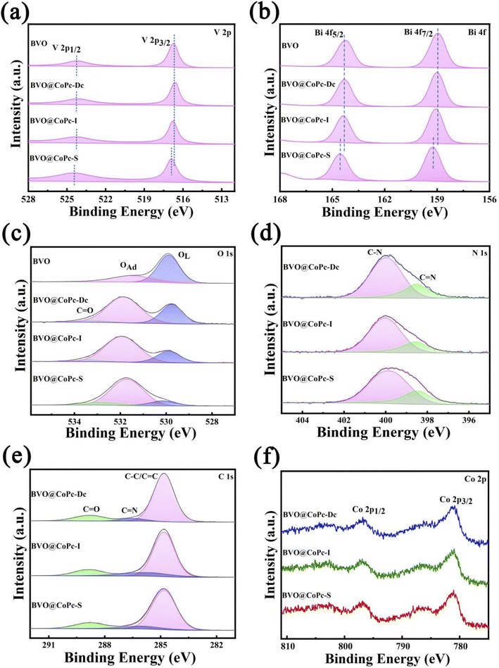 | ||
| Fig. 2 XPS spectra of these prepared photoanodes. (a) V 2p, (b) Bi 4f, (c) O ls, (d) N ls, (e) C ls, and (f) Co 2p. | ||
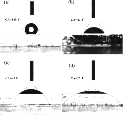
To investigate the relationship between the surface wettability and CoPc loading strategy, the contact angles of these photoanodes were identified as shown in Fig. 3. The contact angle is a paramount index to the surface wettability of the photoanode. The contact angles of BVO, BVO@CoPc-Dc, BVO@CoPc-I, and BVO@CoPc-S are calculated as 140.4°, 63.3°, 41.4°, and 22.5°, respectively. The lower contact angle indicates the better hydrophilicity. Therefore, it can be concluded that incorporating CoPc significantly enhances the photoanode's hydrophilicity. Meanwhile, it can be obtained that BVO@CoPc-S possesses better hydrophilicity than other BVO@CoPc photoanodes. The improved hydrophilicity could promote electrolyte diffusion, accelerating the water oxidation kinetics with better contact between water molecules and active sites.43
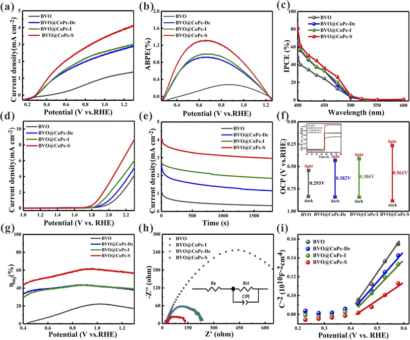
The PEC performance of BVO, BVO@CoPc-Dc, BVO@CoPc-I, and BVO@CoPc-S photoanodes was performed using a conventional three-electrode system in 1 M KBi buffer electrolyte. As shown in Fig. 4a, BVO@CoPc-S photoanode demonstrates the highest photocurrent density of 4.0 mA cm−2 at 1.23 V vs. RHE, which is 3.11, 1.43 and 1.38 times that of BVO (1.32 mA cm−2), BVO@CoPc-Dc (2.8 mA cm−2) and BVO@CoPc-I (2.9 mA cm−2), respectively. This outcome suggests that the incorporation of CoPc could improve the PEC performance. Additionally, BVO@CoPc-S photoanode exhibits optimal water oxidation which may be ascribed to better interface contact and hydrophilicity. The applied bias photon-to-current efficiency (ABPE) and the incident photon-to-current efficiency (IPCE) were conducted to evaluate the photoconversion efficiency of BVO, BVO@CoPc-Dc, BVO@CoPc-I, and BVO@CoPc-S photoanodes. As illustrated in Fig. 4b, compared with the maxima ABPE (0.28%) of the pristine BVO photoanode at 0.86 VRHE, the maxima ABPE (0.92%) of the BVO@CoPc-Dc photoanode at 0.65 VRHE and the maxima ABPE (1.01%) of the BVO@CoPc-Dc photoanode at 0.66 VRHE, the maxima ABPE rises to 1.3% at 0.64 VRHE for BVO@CoPc-S photoanode, indicating BVO@CoPc-S is conductive to the PEC water oxidation process. As can be seen in Fig. 4c, the IPCE of BVO@CoPc-S reaches 81% at 400 nm, which is higher than that of BVO (49%), BVO@CoPc-Dc (66%) and BVO@CoPc-I (67%). These analysis state that BVO@CoPc-S could effectively improve PEC performance with its unique interface contact and hydrophilicity. Linear Scanning Voltammetry (LSV) was used to measure oxygen evolution reaction (OER) curves under dark conditions. As shown in Fig. 4d, the BVO@CoPc-S photoanode has a lower overpotential than other photoanodes attributed to the rapid water oxidation kinetics with better hydrophilicity.
Fig. S2a† demonstrates the transient photocurrent response curves of BVO, BVO@CoPc-Dc, BVO@CoPc-I, and BVO@CoPc-S photoanodes. When the photoanodes are illuminated by light, an anodic photocurrent spike appears due to the production of photogenerated carriers (electrons and holes). With the recombination of photogenerated carriers, the photocurrent gradually decays, and ultimately reaches a steady state. For the quantitative analysis of the charge recombination process, the transient decay rate (D) was calculated with eqn (1), and the transient time constant (τ) could be determined when ln![[thin space (1/6-em)]](https://www.rsc.org/images/entities/char_2009.gif) D = −1.
D = −1.
 | (1) |
As shown in Fig. 4f, open-circuit potential (OCP) differences of BVO, BVO@CoPc-Dc, BVO@CoPc-I, and BVO@CoPc-S between dark and light conditions are 0.293 V, 0.382 V, 0.386 V, and 0.561 V, respectively. The enlarged OCP difference suggests the inhibited charge recombination. Additionally, the photovoltage of BVO@CoPc-S (0.28 V) is 260 mV, 170 mV, and 176 mV higher than that of BVO, BVO@CoPc-Dc, and BVO@CoPc-I, respectively. The accelerated charge transfer dynamics at the photoanode/electrolyte interface is reflected in the higher photovoltage of BVO@CoPc-S. In this work, Na2SO3 is used as the hole sacrificial agent to trap photogenerated holes. The charge injection efficiency (ηinj) of these photoanodes is measured as shown in Fig. 4g. At 1.23 VRHE, BVO@CoPc-S shows higher ηinj values (58%) than that of BVO (18%), BVO@CoPc-Dc (38%) and BVO@CoPc-I (39%). This suggests that a higher quantity of holes at the photoanode/electrolyte interface contribute to the water oxidation reaction. The improved ηinj can attributed to the accelerated electron transfer and reduced charge recombination, thereby facilitating the water oxidation kinetics.
To further investigate the charge behavior at the photoanode/electrolyte interface, electrochemical impedance spectroscopy (EIS) was employed under light illumination. Fig. 4h shows the Nyquist curve and the fitted equivalent circuit model. Rs indicates the series resistance including FTO resistance and contact resistance, while the charge transfer resistance at the interface is represented by Rct. The Rs values of BVO, BVO@CoPc-Dc, BVO@CoPc-I and BVO@CoPc-S are 20.1 Ω, 25.7 Ω, 26.2 Ω and 23.4 Ω, respectively. This result represents the negligible effect of CoPc loading with different load strategies on the Rs. Meanwhile, the Rct values of BVO, BVO@CoPc-Dc, BVO@CoPc-I, and BVO@CoPc-S are 831.6 Ω, 213.4 Ω, 203.4 Ω and 122.5 Ω, respectively. A smaller arc radius generally indicates a faster charge transfer. BVO@CoPc-S exhibits the smallest radius and the lowest Rct value, indicating the facilitated charge transfer at the photoanode/electrolyte interface.
The Mott–Schottky (M–S) curves for the prepared photoanodes are shown in Fig. 4i. These photoanodes display positive slopes, suggesting the n-semiconductor characteristics. In addition, the carrier density of the photoanode can be determined from Mott–Schottky plots using the following equation:
| Nd = (2/e0εε0)[d(1/C2)/dV]−1 | (2) |
On the basis of the aforementioned measurements and analysis, the PEC water-splitting mechanism of BVO@CoPc-S is proposed (Scheme 2). At first, the generation and separation of the electron–hole pairs occurs under illumination. Due to CoPc modification, photogenerated holes migrate to CoPc and participate in the water oxidation reaction. In addition, CoPc could provide the active site as a co-catalyst, which facilitated the water oxidation kinetics. Meanwhile, the hydrophilic surface of BVO@CoPc-S affords nice penetration and diffusion of the electrolyte, indeed promoting water oxidation. This good photoanode/electrolyte interface allows the generated holes to quickly participate in water oxidation, accelerates water oxidation kinetics and boosts the water splitting efficiency of PEC.
3. Conclusions
To sum up, super-hydrophilic BVO@CoPc-S composite photoanode was successfully prepared via a solvothermal treatment method. BVO@CoPc-S photoanode attained a remarkable photocurrent density of 4.0 mA cm−2 at 1.23 VRHE and the maximum ABPE of 1.3% at 0.64 VRHE. The exceptional PEC performance can be ascribed to the introduction of CoPc with providing active sites and super-hydrophilicity accelerating electrolyte diffusion. Benefit from this, the electrode can better match the electrolyte interface, which contribute to photogenerated carriers to be more efficiently injected into the electrolyte, effectively suppresses the recombination of bulk surface charges, and thus accelerates the surface reaction kinetics. Our work based on hydrophilic interfacial engineering provides valuable insights for designing and developing advanced hybrid photoanode structures for efficient PEC water splitting.Data availability
All data are available in the ESI† and within the main manuscript.Conflicts of interest
The authors declare no conflicts of interest.Acknowledgements
This work is financially supported by the National Natural Science Foundation of China (Grant No. 22269002), Natural Science Foundation of Guangxi Province (Grant No. 2023GXNSFBA026182), and the Open Research Fund of Songshan Lake Materials Laboratory (Grant No. 2022SLABFN08).References
- R. T. Gao, D. He, L. J. Wu, K. Hu, X. H. Liu, Y. G. Su and L. Wang, Angew. Chem., Int. Ed., 2020, 59, 6213–6218 CrossRef CAS PubMed.
- V. O. Smilyk, S. S. Fomanyuk, I. A. Rusetskyi, M. O. Danilov and G. Y. Kolbasov, Monatsh. Chem., 2024, 155, 319–323 CrossRef CAS.
- H. Wu, L. Zhang, A. J. Du, R. Irani, R. van de Krol, F. F. Abdi and Y. H. Ng, Nat. Commun., 2022, 13, 6231 CrossRef CAS PubMed.
- J. Arun, S. Nachiappan, G. Rangarajan, R. P. Alagappan, K. P. Gopinath and E. Lichtfouse, Environ. Chem. Lett., 2023, 21, 339–362 CrossRef CAS PubMed.
- A. Fujishima and K. Honda, Nature, 1972, 238, 37–38 CrossRef CAS PubMed.
- S. Lardhi, L. Cavallo and M. Harb, J. Phys. Chem. Lett., 2020, 11, 5497–5503 CrossRef CAS PubMed.
- A. Yamakata, C. S. K. Ranasinghe, N. Hayashi, K. Kato and J. J. M. Vequizo, ACS Appl. Energy Mater., 2020, 3, 1207–1214 Search PubMed.
- Y. H. Guo, Y. Q. Wu, Z. Q. Wang, D. J. Dai, X. L. Liu, Q. Q. Zhang, Z. Y. Wang, Y. Y. Liu, Z. K. Zheng, H. F. Cheng, B. B. Huang, Y. Dai and P. Wang, Appl. Surf. Sci., 2023, 614, 156164 CrossRef CAS.
- Y. R. Song, X. M. Zhang, Y. X. Zhang, P. L. Zhai, Z. W. Li, D. F. Jin, J. Q. Cao, C. Wang, B. Zhang, J. F. Gao, L. C. Sun and J. G. Hou, Angew. Chem., Int. Ed., 2022, 61, e202200946 Search PubMed.
- Z. Y. Tao, J. W. Yang, Y. Wu, Q. Zhao, J. P. Li and G. Liu, Int. J. Hydrogen Energy, 2024, 61, 851–858 CrossRef CAS.
- Z. M. Zhou, J. J. Chen, Q. L. Wang, X. X. Jiang and Y. Shen, Chin. J. Catal., 2022, 43, 433–441 CrossRef CAS.
- D. M. Chen, X. L. Li, J. Y. Huang, Y. X. Chen, Z. L. Liu and Y. C. Huang, ACS Appl. Energy Mater., 2023, 6, 8495–8502 CrossRef CAS.
- Y. P. Li, H. Han, A. D. Xu, Y. M. Fu, C. F. Zhu, L. J. Cheng and Y. G. Li, Inorg. Chem., 2023, 62, 17851–17860 Search PubMed.
- J. C. Wang, Y. Zhang, J. Bai, J. H. Li, C. H. Zhou, L. Li, C. Y. Xie, T. S. Zhou, H. Zhu and B. X. Zhou, J. Colloid Interface Sci., 2023, 644, 509–518 CrossRef CAS PubMed.
- M. R. Wang, Z. Y. Wang, B. Zhang, W. Y. Jiang, X. L. Bao, H. F. Cheng, Z. K. Zheng, P. Wang, Y. Y. Liu, M. H. Whangbo, Y. J. Li, Y. Dai and B. B. Huang, ACS Catal., 2020, 10, 13031–13039 CrossRef CAS.
- G. Q. Liu, F. Li, Y. Zhu, J. Y. Li and L. C. Sun, RSC Adv., 2020, 10, 28523–28526 RSC.
- J. Zuo, H. L. Guo, S. Chen, Y. Pei and C. J. Liu, Catal. Sci. Technol., 2023, 13, 3963–3973 RSC.
- X. K. Wan, G. Z. Liu, X. Y. Wang, D. S. Lu, Y. M. Fu, X. J. Guan, C. Hu, N. Rong and H. T. Wang, J. Photochem. Photobiol., A, 2024, 451, 115527 Search PubMed.
- Z. J. Sun, C. W. Xu, Z. Li, F. Guo, B. S. Liu, J. H. Liu, J. Zhou, Z. Q. Yu, X. He and D. C. Jiang, New J. Chem., 2022, 46, 9111–9118 RSC.
- X. L. Shen, L. Zhao, W. Q. Fan, J. S. Ren, Q. Wang, A. J. Wang, D. H. Shang and W. H. Zhu, Appl. Surf. Sci., 2021, 564, 150463 CrossRef CAS.
- M. M. Fan, Z. Y. Tao, Q. Zhao, J. P. Li, G. Liu and C. Zhao, Adv. Mater. Technol., 2023, 8, 2201835 CrossRef CAS.
- Z. Cai, Y. S. Zhang, Y. X. Zhao, Y. S. Wu, W. W. Xu, X. M. Wen, Y. Zhong, Y. Zhang, W. Liu, H. L. Wang, Y. Kuang and X. M. Sun, Nano Res., 2019, 12, 345–349 CrossRef CAS.
- S. S. Chen, S. Shen, G. J. Liu, Y. Qi, F. X. Zhang and C. Li, Angew. Chem., Int. Ed., 2015, 54, 3047–3051 CrossRef CAS PubMed.
- T. T. Zhang, P. Lin, N. Wei and D. A. Wang, ACS Appl. Mater. Interfaces, 2020, 12, 20110–20118 CrossRef CAS PubMed.
- P. F. Yue, H. D. She, L. Zhang, B. Niu, R. Lian, J. W. Huang, L. Wang and Q. Z. Wang, Appl. Catal., B, 2021, 286, 119875 CrossRef CAS.
- Y. B. Kuang, T. Yamada and K. Domen, Joule, 2017, 1, 290–305 CrossRef CAS.
- P. Mane, I. V. Bagal, H. Bae, V. Burungale, C. Seong, S. W. Ryu and J. S. Ha, Adv. Sustainable Syst., 2022, 6, 2200014 CrossRef CAS.
- T. W. Kim and K. S. Choi, Science, 2014, 343, 990–994 CrossRef CAS PubMed.
- J. B. Pan, B. H. Wang, S. Shen, L. Chen and S. F. Yin, Angew. Chem., Int. Ed., 2023, 62, e202307246 CrossRef CAS PubMed.
- Z. X. Liu, F. Y. Zhao, X. H. Liu, Y. H. Fu, Y. Song, P. Y. Wang, X. X. Zhang, G. W. Wang and H. C. Ma, Langmuir, 2024, 40, 1348–1357 CrossRef CAS PubMed.
- S. C. Wang, P. Chen, J. H. Yun, Y. X. Hu and L. Z. Wang, Angew. Chem., Int. Ed., 2017, 56, 8500–8504 CrossRef CAS PubMed.
- R. L. Wang, Y. Kuwahara, K. Mori, C. Louis, Y. Y. Bu and H. Yamashita, J. Mater. Chem. A, 2020, 8, 21613–21622 RSC.
- K. S. Joya, N. Morlanés, E. Maloney, V. Rodionov and K. Takanabe, Chem. Commun., 2015, 51, 13481–13484 RSC.
- Y. D. Liu, Y. Jiang, F. Li, F. S. Yu, W. C. Jiang and L. X. Xia, J. Mater. Chem. A, 2018, 6, 10761–10768 RSC.
- G. S. Liu, S. W. Liu, Q. F. Lu, H. Y. Sun and Z. L. Xiu, RSC Adv., 2014, 4, 53402–53406 RSC.
- M. Y. Zhang, C. L. Shao, Z. C. Guo, Z. Y. Zhang, J. B. Mu, T. P. Cao and Y. C. Liu, ACS Appl. Mater. Interfaces, 2011, 3, 369–377 Search PubMed.
- Z. Y. Long, X. Y. Zheng and H. F. Shi, Sci. China Mater., 2024, 67, 550–561 CrossRef CAS.
- D. C. Jiang, L. Zhang, Q. D. Yue, T. T. Wang, Q. Huang and P. W. Du, Int. J. Hydrogen Energy, 2021, 46, 15517–15525 CrossRef CAS.
- J. Choi, P. Wagner, S. Gambhir, R. Jalili, D. R. MacFarlane, G. G. Wallace and D. L. Officer, ACS Energy Lett., 2019, 4, 666–672 CrossRef CAS.
- X. S. Hu, Q. Z. Wang, Y. Li, Y. Meng, L. Wang, H. D. She and J. W. Huang, J. Colloid Interface Sci., 2022, 607, 219–228 CrossRef CAS PubMed.
- O. L. Li, L. Qin, N. Takeuchi, K. Kim and T. Ishizaki, Catal. Today, 2019, 337, 155–161 CrossRef CAS.
- W. H. Xie, Z. B. Yu, H. C. Huang, R. H. Jiang, S. Q. Yao, J. Huang, Y. P. Hou, S. B. Yin, R. L. Mo and C. Wu, J. Colloid Interface Sci., 2024, 665, 977–987 CrossRef CAS PubMed.
- S. P. Wan, C. R. Dong, J. Jin, J. Li, Q. Zhong, K. Zhang and J. H. Park, ACS Energy Lett., 2022, 7, 3024–3031 CrossRef CAS.
Footnote |
| † Electronic supplementary information (ESI) available. See DOI: https://doi.org/10.1039/d4ra08254k |
| This journal is © The Royal Society of Chemistry 2025 |

