 Open Access Article
Regulating cation–solvent interactions in PVDF-based solid-state electrolytes for advanced Li metal batteries†
Zhian
Zhang
a,
Meng
Ye
a,
Jianhua
Chen
a,
Xiaopeng
Fu
a,
Xunzhu
Zhou
b,
Limin
Zheng
a,
Liqing
He
c,
Zhenguo
Wu
 a,
Amit
Kumar
 d,
Lin
Li
 *b,
Fang
Wan
 *a and
Xiaodong
Guo
 a
a
aSchool of Chemical Engineering, Sichuan University, Chengdu 610065, P. R. China. E-mail: wanfang2022@scu.edu.cn
bCollege of Chemistry and Materials Engineering, Wenzhou University, Wenzhou, Zhejiang 325035, P. R. China. E-mail: linli@wzu.edu.cn
cHefei General Machinery Research Institute Co., Ltd, Hefei 230031, P. R. China
dEastCHEM, School of Chemistry, University of St. Andrews, St. Andrews, KY169ST, UK
First published on 12th February 2025
Abstract
Poly(vinylidene fluoride) (PVDF)-based solid-state electrolytes (SSEs) have been considered promising candidates for advanced Li metal batteries due to their adequate mechanical strength and acceptable thermal stability. However, the poor compatibility between residual solvent and Li metal inevitably leads to fast capacity decay. Herein, we propose a multifunctional cation-anchor strategy to regulate solvation chemistry in PVDF-based SSEs to boost the electrochemical performance of Li metal batteries. The strong interaction between N,N-dimethylformamide (DMF) and Zn2+ decreases the participation of DMF in the inner solvation sheath of Li+, inducing an anion-reinforced solvation structure. The unique solvation structure facilitates the formation of a robust LiF-rich solid electrolyte interphase layer to eliminate interfacial side reactions. In addition, a continuous ion-conducting network is constructed by introducing extra TFSI− anions, enabling accelerated Li+ transport. As a result, the corresponding Li‖Li symmetrical cells achieve stable lithium plating/stripping over 780 h, and the rate performance and cycling stability of Li‖LiFePO4 cells are significantly improved. This work highlights the key role of regulation of solvation chemistry in PVDF-based SSEs for Li metal batteries.
Introduction
The rapid advancement of electric vehicles has driven a growing demand for high-energy-density battery technology to eliminate range anxiety.1–4 However, the traditional lithium-ion batteries (LIBs) based on graphite anodes can't satisfy the ever-increasing demand of the driver. Li metal anodes with the merits of ultrahigh theoretical specific capacity (3860 mA h g−1) and low redox potential (−3.040 V versus the standard hydrogen electrode) have attracted extensive attention.5–7 Unfortunately, Li metal generally suffers from undesired Li dendrite growth, which induces deteriorated electrochemical performance with severe safety issues. In addition, the inherent flammability of the conventional liquid electrolyte further aggravates safety threats and even explosions.8–10 These issues inevitably hinder the practical application of Li metal batteries (LMBs). Therefore, it's urgent to explore an effective strategy to realize stable and safe LIBs.11–13Organic–inorganic composite solid-state electrolytes (SSEs) combine the advantages of organic polymer SSE14–16 and inorganic SSE17,18 and have attracted extensive attention for high-performance LMBs.19 In general, the organic polymer, as an important component of organic–inorganic composite SSE, is closely related to the electrochemical performance of LMBs. Until now, various organic polymers have been applied in organic–inorganic composite SSEs, such as polyethylene oxide (PEO),20,21 poly(vinylidene fluoride) (PVDF),22–25 poly(vinylidene fluoride-co-hexafluoropropylene) (PVDF-HFP)25–28 and polyacrylonitrile (PAN).29 Among these, PVDF is considered a promising candidate due to its superior mechanical strength, excellent thermal stability, and outstanding anti-oxidation ability.30 Nevertheless, the residual solvent N,N-dimethylformamide (DMF) is unavoidable during the preparation of PVDF-based SSE, which exhibits poor compatibility with Li metal resulting in several interfacial side reactions with fast capacity decay.31–34 Meanwhile, the PVDF-based organic–inorganic composite SSE shows an unsatisfactory ionic conductivity, leading to poor rate performance. At present, various strategies are demonstrated effectively to eliminate the interfacial side reactions and improve ionic conductivity, including salt optimization,35 functional group grafting, etc.36,37 However, the increased cost of these methods inevitably hinders their practical application. Therefore, it's highly imperative to explore economic and facile strategies to construct PVDF-based organic–inorganic composite SSEs with eliminated interfacial side reactions and improved ionic conductivity for safe and stable LMBs.
Herein, Zn(TFSI)2 is employed as a multifunctional additive in PVDF–LiTFSI–Li6.4La3Zr1.4Ta0.6O12 (LLZTO) composite SSE to regulate solvation chemistry. The strong interaction between DMF and Zn2+ weakens the ability of DMF to participate in the Li+ inner solvation sheath, inducing an anion-reinforced solvation structure to construct a robust LiF-rich SEI layer. This layer can effectively avoid the interfacial side reactions and facilitate uniform Li deposition. Meanwhile, the limited migration ability of Zn2+ in the electrolyte effectively immobilizes DMF within the electrolyte. The extra anions form a highly efficient Li+ conductive network, achieving a high ionic conductivity of 1.06 × 10⁻³ S cm−1 at 30 °C. As a result, PVDF–LiTFSI–LLZTO–Zn(TFSI)2 SSE achieves stable lithium plating/stripping for 780 h in Li‖Li symmetric cells. The reversible capacity, rate performance, and cycling stability of Li‖LiFePO4 (LFP) cells are also significantly improved.
Results and discussion
According to the reported literature, residual solvent DMF is closely related to the electrochemical performance of PVDF-based SSEs and is inescapable due to the electrostatic adsorption between the dissociated Li+ and the C![[double bond, length as m-dash]](https://www.rsc.org/images/entities/char_e001.gif) O of DMF (Fig. S1†).38 DMF migrates to the Li anode surface along with Li+ resulting in several interphase side reactions and fast capacity decay due to the poor compatibility between DMF and Li metal (Fig. 1a top). In addition, the PVDF-based SSE generally suffers from low ionic conductivity, inducing an unsatisfactory electrochemical performance. Herein, a cation anchor strategy is proposed to boost the electrochemical performance of PVDF-based solid-state electrolyte by the introduction of a metal salt. As shown in Fig. 1a (bottom), the residual solvent DMF is anchored by the cation due to the strong interaction, which effectively eliminates the interphase side reaction and regulates the Li+ solvation chemistry. The unique Li+ solvation chemistry facilitates the formation of a robust LiF-rich SEI layer to avoid the growth of Li dendrite. Meanwhile, a fast Li+ transfer channel is constructed by the extra anions with high ionic conductivity. Theoretical calculations are first carried out to screen the cations by evaluating their interactions with DMF. As displayed in Fig. 1b and S2,† Zn2+–DMF and TFSI−–Zn2+–DMF show the strongest binding energy compared to that of Li+, Na+, K+ and Mg2+, indicating the superior anchoring ability of Zn2+ for DMF (Table S1†). Thus, PVDF–LiTFSI–LLZTO (denoted as PLL) is selected as the control electrolyte and PVDF–LiTFSI–LLZTO–Zn(TFSI)2 (denoted as PLLZ) for the optimized electrolyte.
O of DMF (Fig. S1†).38 DMF migrates to the Li anode surface along with Li+ resulting in several interphase side reactions and fast capacity decay due to the poor compatibility between DMF and Li metal (Fig. 1a top). In addition, the PVDF-based SSE generally suffers from low ionic conductivity, inducing an unsatisfactory electrochemical performance. Herein, a cation anchor strategy is proposed to boost the electrochemical performance of PVDF-based solid-state electrolyte by the introduction of a metal salt. As shown in Fig. 1a (bottom), the residual solvent DMF is anchored by the cation due to the strong interaction, which effectively eliminates the interphase side reaction and regulates the Li+ solvation chemistry. The unique Li+ solvation chemistry facilitates the formation of a robust LiF-rich SEI layer to avoid the growth of Li dendrite. Meanwhile, a fast Li+ transfer channel is constructed by the extra anions with high ionic conductivity. Theoretical calculations are first carried out to screen the cations by evaluating their interactions with DMF. As displayed in Fig. 1b and S2,† Zn2+–DMF and TFSI−–Zn2+–DMF show the strongest binding energy compared to that of Li+, Na+, K+ and Mg2+, indicating the superior anchoring ability of Zn2+ for DMF (Table S1†). Thus, PVDF–LiTFSI–LLZTO (denoted as PLL) is selected as the control electrolyte and PVDF–LiTFSI–LLZTO–Zn(TFSI)2 (denoted as PLLZ) for the optimized electrolyte.
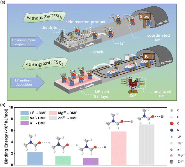 | ||
| Fig. 1 (a) Schematic illustration for the action mechanism of Zn(TFSI)2 in PVDF-based electrolyte. (b) The binding energy of Li+–DMF, Na+–DMF, K+–DMF, Mg2+–DMF and Zn2+–DMF. | ||
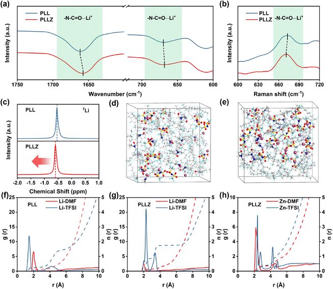
Fourier-transform infrared spectroscopy (FTIR) was employed to investigate the role of Zn2+ in PVDF-based SSE. As shown in Fig. 2a, the characteristic peaks of N–C![[double bond, length as m-dash]](https://www.rsc.org/images/entities/char_e001.gif) O⋯Li+ coordination (1660.5 and 669.0 cm−1) shift to a lower wavenumber after introducing Zn(TFSI)2, demonstrating the stronger interaction between DMF and Zn2+.39 The red shift of the N–C
O⋯Li+ coordination (1660.5 and 669.0 cm−1) shift to a lower wavenumber after introducing Zn(TFSI)2, demonstrating the stronger interaction between DMF and Zn2+.39 The red shift of the N–C![[double bond, length as m-dash]](https://www.rsc.org/images/entities/char_e001.gif) O⋯Li+ peak in Raman spectra further proves the strong adsorption ability of Zn2+ for DMF (Fig. 2b).35 The introduction of Zn(TFSI)2 not only provides Zn2+ to anchor DMF, but also introduces additional TFSI− anions that strengthen the anion network of the electrolyte. The anion network formed by TFSI− provides additional binding sites for Li+ transport in the electrolyte, which is beneficial to Li+ transport. To investigate the Li+ environment in electrolytes, 7Li solid-state nuclear magnetic resonance (NMR) spectra were recorded, as shown in Fig. 2c. The peak shifts upfield from −0.54 to −0.60 ppm after introducing the Zn(TFSI)2 salt, indicating the heightened affinity between TFSI− and Li+ and the formation of an anion-reinforced solvation structure. This strong interaction drives Li+ to move efficiently within the TFSI− anion network. Consequently, Li+ in PLLZ electrolyte can migrate through a well-developed network of TFSI− anions rather than being confined to polymer chain pathways alone, creating a more cohesive ionic conduction pathway and positively impacting overall ionic conductivity (Fig. S3†).32–34,40
O⋯Li+ peak in Raman spectra further proves the strong adsorption ability of Zn2+ for DMF (Fig. 2b).35 The introduction of Zn(TFSI)2 not only provides Zn2+ to anchor DMF, but also introduces additional TFSI− anions that strengthen the anion network of the electrolyte. The anion network formed by TFSI− provides additional binding sites for Li+ transport in the electrolyte, which is beneficial to Li+ transport. To investigate the Li+ environment in electrolytes, 7Li solid-state nuclear magnetic resonance (NMR) spectra were recorded, as shown in Fig. 2c. The peak shifts upfield from −0.54 to −0.60 ppm after introducing the Zn(TFSI)2 salt, indicating the heightened affinity between TFSI− and Li+ and the formation of an anion-reinforced solvation structure. This strong interaction drives Li+ to move efficiently within the TFSI− anion network. Consequently, Li+ in PLLZ electrolyte can migrate through a well-developed network of TFSI− anions rather than being confined to polymer chain pathways alone, creating a more cohesive ionic conduction pathway and positively impacting overall ionic conductivity (Fig. S3†).32–34,40
Subsequently, molecular dynamics (MD) simulations were employed to further investigate the coordination of Li+ in PPL and PPLZ electrolytes (Fig. 2d and e). The radial distribution function (RDF) results show that the coordination between Li+ and DMF in PLLZ electrolyte is weaker than that in PLL electrolyte (Fig. 2f and g). This can be attributed to the competitive interaction of Zn2+ with DMF, which weakens the Li+–DMF coordination. The weakened coordination between Li+ and DMF induces the formation of a TFSI−-reinforced Li+ solvation structure in PPLZ electrolyte (Fig. S4 and Table S2†). In addition, Fig. 2h demonstrates the strong interaction between DMF and Zn2+, which weakens the participation of DMF in the solvation sheath of Li+ and promotes the formation of a TFSI−-reinforced Li+ solvation structure. This provides the possibility for the formation of a LiF-rich SEI layer, which may facilitate uniform Li+ deposition at the interface and improve the overall stability of the system.
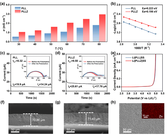
The ionic conductivity of electrolytes at different temperatures was tested in Fig. S5 and S6.† PLLZ electrolyte exhibits significantly higher ionic conductivity compared to PLL electrolyte at different temperatures (Fig. 3a). At 30 °C, the ionic conductivity of PLLZ electrolyte can reach up to 1.06 × 10⁻³ S cm−1, which is about twice of PLL electrolyte with 5.52 × 10⁻⁴ S cm−1 (Table S3†). The X-ray diffraction (XRD) patterns of the two electrolytes show no significant differences, indicating that the increase in ionic conductivity was not due to changes in the crystallinity of PVDF (Fig. S7†). In addition, a lower energy barrier of 0.196 eV is observed in PLLZ electrolyte according to the varying-temperature ionic conductivity, compared with 0.223 eV in PLL electrolyte (Fig. 3b). This result suggests that the introduction of Zn(TFSI)2 results in a more complete TFSI− network, thereby reducing the energy barrier for Li+ migration. As depicted in Fig. 3c and d, the Li+ transference number of 0.50 in PLLZ electrolyte is also higher than that of 0.32 in PLL electrolyte, demonstrating that the introduction of Zn2+ can restrain the movement of TFSI− anions. To confirm whether Zn2+ contributes to ion transport in PLLZ electrolyte, an additional PLZ electrolyte containing only the Zn(TFSI)2 salt was designed. As shown in Fig. S8 and S9,† the PLZ electrolyte exhibits a relatively low ionic conductivity of 4.8 × 10⁻⁶ S cm−1 and an ultralow Zn2+ transference number, proving that Zn2+ is not the charge carrier to boost the ion transport in the electrolyte.41 These findings suggest that the introduction of Zn(TFSI)2 can improve the transfer ability of Li+. LSV curves indicate that both PLL and PLLZ electrolytes possess similar electrochemical stability windows (>4.5 V), demonstrating their potential compatibility with high-voltage cathode materials (Fig. 3e). Cross-sectional SEM images were recorded to reveal the thickness of the PLL and PLLZ SSEs (Fig. 3f, g). The thickness of these electrolytes is approximately 70 μm, corresponding to the thickness test using a micrometer caliper (Fig. S10†). Energy dispersive spectroscopy (EDS) mapping revealed that Zn(TFSI)2 is uniformly dispersed throughout the PVDF matrix (Fig. 3h).
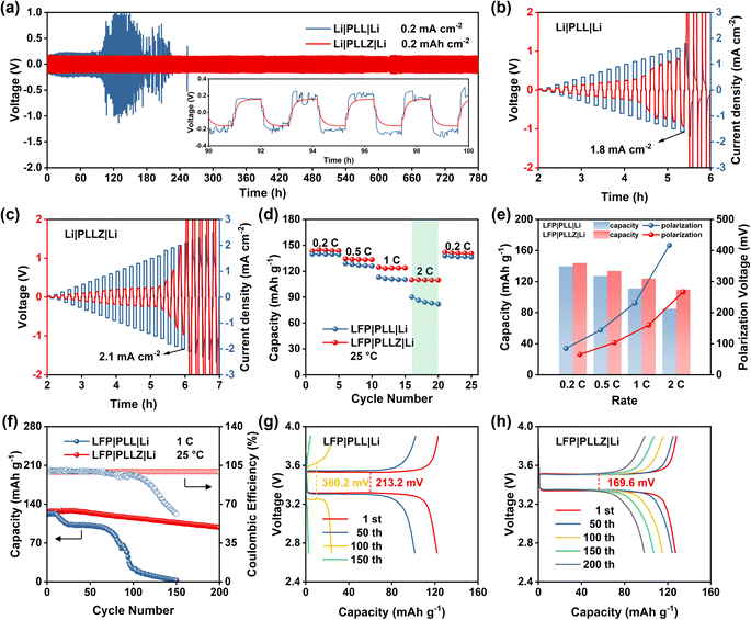
Subsequently, the superiority of the PLLZ electrolyte is evaluated by the Li‖Li symmetric cells. As shown in Fig. 4a, Li‖Li symmetric cells with PLL electrolyte exhibit gradually increased overpotential, which fluctuates from about 200 to 1000 mV. This is attributed to the severe side reactions between DMF and Li metal at the anode interface. The continuous accumulation of by-products seriously impedes the interface ion transport, leading to the open circuit of cells at about 110 h. In PLLZ electrolyte, DMF has been anchored by Zn2+, which greatly inhibits the side reactions between DMF and the Li anode. This enables stable long-term cycling with a lower overpotential of ca. 160 mV for over 780 h. In comparison to recently reported PVDF-based composite solid electrolytes, the PLLZ electrolyte demonstrates superior performance in terms of lithium anode stability. As summarized in Table S4,† previous studies reported Li‖Li cycling lifetimes ranging from 200 to 500 h, whereas the PLLZ electrolyte achieves an extended cycling lifetime of 780 h. In addition, Li|PLLZ|Li cells also deliver a higher critical current density of 2.1 mA cm−2, compared with 1.8 mA cm−2 in Li|PLL|Li cells, highlighting the enhanced interfacial stability between PLLZ and the Li anode (Fig. 4b and c).
Li‖LFP cells are further assembled to discuss the application potential of PLLZ SSE in solid-state LMBs. As shown in Fig. 4d, S11 and S12,† Li|PLLZ|LFP cells deliver average discharge capacities of 143.9, 133.7, 123.9, and 109.9 mA h g−1 at 0.2, 0.5, 1.0, and 2.0C, which are higher than that of 139.7, 127.2, 111.2, and 85.1 mA h g−1 in Li|PLL|LFP cells. The superiority of PLLZ electrolyte in lowering the polarization is more pronounced as the current density increases (Fig. 4e), with a lower value of 266.9 mV in PLLZ electrolyte than that of 416.6 mV in PLL electrolyte at 2.0C. These may be attributed to the high ionic conductivity and stable anode interface of the PLLZ electrolyte. As expected, the Li|PLLZ|LFP cell maintains a high retention of 90% after 100 cycles with an average coulombic efficiency of over 99% at 1.0C (Fig. 4f), in sharp contrast to the rapid capacity decay in the Li|PLL|LFP cell. After 200 cycles, the Li|PLLZ|LFP cell still retains a high capacity, demonstrating excellent cycling stability. Additionally, the potential polarization of the Li|PLL|LFP cell is 213.2 mV at the first cycle and increases to 380.2 mV after 100 cycles (Fig. 4g and S13†). However, the potential polarization of the Li|PLLZ|LFP cell is 169.6 mV at the first cycle and displays no obvious increase after 200 cycles (Fig. 4h). These results highlight the superiority of PLLZ SSE in improving the stability of the Li metal anode.
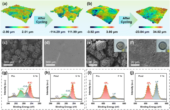
To further demonstrate the superior anode stability of the PLLZ electrolyte, the PLL and PLLZ electrolytes as well as their corresponding Li metal anodes after cycling were analyzed. 3D/2D optical profile images of the two electrolytes are presented in Fig. 5a, b, S14, and S15.† PLL and PLLZ electrolytes exhibit similar surface roughness before cycling, while significant changes occur after cycling for 780 h at 0.2 mA cm−2 in Li‖Li symmetric cells. The longitudinal height between peaks and valleys in PLL electrolyte increases over 200 μm, indicating the serious damage caused by lithium dendrites and by-products. In contrast, the surface roughness of PLLZ electrolyte changes lightly after cycling, with the longitudinal height being controlled to about 50 μm. This result is further supported using scanning electron microscopy (SEM) images. Both the PLL and PLLZ electrolytes exhibit smooth surfaces before cycling (Fig. 3h and S16†). After cycling, the surface of the PLL electrolyte exhibits pronounced protrusions due to severe side reactions, while the PLLZ electrolyte still retains a relatively flat morphology (Fig. 5c and d). In addition, the SEM image of the anode can directly indicate the severity of side reactions. Compared to fresh Li, the surface of the cycled Li anode in Li|PLL|Li (denoted as PLL-anode) shows numerous protrusions and cracks (Fig. 5e and S17†). The poor surface morphology of the anode seriously worsens the contact with the electrolyte, hindering the plating/stripping of Li+ and thus eventually leading to the failure of the cell. Nevertheless, the cycled Li anode in Li|PLLZ|Li (denoted as PLLZ-anode) exhibits a more continuous and dense surface morphology, indicating improved interfacial compatibility and mechanical contact (Fig. 5f).
The Li anodes in Li‖Li symmetric cells after cycling were further examined by X-ray photoelectron spectroscopy (XPS, Fig. S18 and S19†). The C 1s spectra of the PLL-anode and PLLZ-anode indicate that the interphases are made up of various organic and inorganic compounds (Fig. 5g and h). The peaks around 286.0, 289.5, and 293.0 eV are classified as characteristic peaks of C–O, Li2CO3, and –CF3, respectively.34,42 Both organic product C–O and inorganic product Li2CO3 are poor conductors for Li+, which prevent the transport of Li+ at the interface. The C 1s spectra of the cycled PLLZ-anode show a significantly lower relative content of undesirable side products compared to the cycled PLL-anode. This suggests that PLLZ electrolyte has fewer adverse side reactions on the anode surface. The reduction in adverse side reactions is primarily attributed to the suppression of DMF migration by Zn2+, thereby preventing the decomposition of DMF at the Li metal surface. The F 1s spectra show that more LiF is generated on the surface of the cycled PLLZ-anode (Fig. 5i and j). LiF acts as a benign Li+ conductor, which not only inhibits the subsequent decomposition of the electrolyte but also provides fast Li+ transport media.43 This indicates that the introduction of Zn(TFSI)2 optimizes the composition of the SEI layer, promoting uniform Li+ deposition. In addition, Zn 1s spectra demonstrate that Zn2+ is not deposited on the cycled Li metal anodes, which confirms that Zn2+ does not migrate in PLLZ electrolyte (Fig. S20†). The above characterization studies of PLLZ and PLL electrolytes and corresponding Li metal anodes reveal that the PLLZ electrolyte exhibits excellent stability against the Li metal anode.
Conclusion
In this work, we propose a feasible multifunctional cation-anchor strategy to guarantee that PVDF-based organic–inorganic composite SSE simultaneously possesses superior anode interface stability and a fast Li+ transport network. On the one hand, the strong electron-withdrawing cation Zn2+ effectively decreases the coordination number of DMF and increases the anion participation in the Li+ solvation structure to form a robust SEI for the stable cycle. The inherent sluggish migration ability of Zn2+ avoids the contact of DMF with Li metal, thus reducing interfacial side reactions. On the other hand, the introduced additional TFSI− anions form a conductive network for fast Li+ transport. As a result, the PLLZ electrolyte displays a high ionic conductivity of 1.06 × 10⁻³ S cm−1 at 30 °C, which is about twice that (5.52 × 10⁻⁴ S cm−1) of the electrolyte without the Zn(TFSI)2 additive. Moreover, the assembled Li symmetric cell can cycle for over 780 hours and the Li|PLLZ|LFP cell achieves enhanced rate capability and cycling performance. This work provides a new method for simultaneously eliminating interfacial side reactions and improving ionic conductivity in PVDF-based SSEs.Data availability
The data supporting the findings of this study are available within the article or its ESI.†Author contributions
L. Li, F. Wan, and X. Guo conceived and designed the project. Z. Zhang, M. Ye, L. He, and Z. Wu performed the synthetic and characterization work. J. Chen, X. Fu and A. Kumar carried out physicochemical property measurements. Z. Zhang, X. Zhou, and L. Zheng carried out the electrochemical performance measurements. All the authors analyzed the results and co-wrote the manuscript.Conflicts of interest
The authors declare no conflict of interest.Acknowledgements
This work was supported by the National Natural Science Foundation of China (22425804, 52202286 and 22309002), Sichuan Science and Technology Program (2024NSFTD0001), Natural Science Foundation of Zhejiang Province (LY24B030006), Key Research and Development Program of Zhejiang Province (2024C01057), Science and Technology Plan Project of Wenzhou Municipality (ZG202405), Wenzhou Association for Science and Technology Innovation Program (NLTS2024-013), and Basic Research Project of Wenzhou City (G20220016).References
- X. Zhang, S. Wang, C. Xue, C. Xin, Y. Lin, Y. Shen, L. Li and C. W. Nan, Adv. Mater., 2019, 31, 1806082 CrossRef PubMed.
- Z. Wang, J. Zhao, X. Zhang, Z. Rong, Y. Tang, X. Liu, L. Zhu, L. Zhang and J. Huang, eScience, 2023, 3, 100087 CrossRef.
- L. Wang, S. Xu, Z. Wang, E. Yang, W. Jiang, S. Zhang, X. Jian and F. Hu, eScience, 2023, 3, 100090 CrossRef.
- Z. Fan, X. Zhou, J. Qiu, Z. Yang, C. Lei, Z. Hao, J. Li, L. Li, R. Zeng and S.-L. Chou, Angew. Chem., Int. Ed., 2023, 62, e202308888 CrossRef CAS PubMed.
- X. Chen, H. R. Li, X. Shen and Q. Zhang, Angew. Chem., Int. Ed., 2018, 57, 16643–16647 CrossRef CAS PubMed.
- Y. Liu, Z. Jin, Z. Liu, H. Xu, F. Sun, X. Q. Zhang, T. Chen and C. Wang, Angew. Chem., Int. Ed., 2024, 63, e202405802 CrossRef CAS PubMed.
- J. Zhang, Q. Li, Y. Zeng, Z. Tang, D. Sun, D. Huang, Y. Tang and H. Wang, ACS Energy Lett., 2023, 8, 1752–1761 CrossRef CAS.
- G. M. Hobold, C. Wang, K. Steinberg, Y. Li and B. M. Gallant, Nat. Energy, 2024, 9, 580–591 CrossRef CAS.
- C. Zhang, J. Yu, Y. Cui, Y. Lv, Y. Zhang, T. Gao, Y. He, X. Chen, T. Li, T. Lin, Q. Mi, Y. Yu and W. Liu, Nat. Commun., 2024, 15, 5325 CrossRef CAS PubMed.
- N. Zhang, W. Li, R. Li, H. Di, B. Wen and L. Zhang, Small, 2024, e2402164 CrossRef PubMed.
- X. B. Cheng, T. Z. Hou, R. Zhang, H. J. Peng, C. Z. Zhao, J. Q. Huang and Q. Zhang, Adv. Mater., 2016, 28, 2888–2895 CrossRef CAS PubMed.
- Z. Jia, M. Jia, Q. Sun, N. Wang, Z. Bi and X. Guo, Energy Storage Mater., 2024, 68, 103325 CrossRef.
- K. Zhou, X. Dai, L. Zhang, H. Liu, T. Li, X. Zhang, J. Wen, G. Huang and S. Xu, Adv. Energy Mater., 2024, 202402782 Search PubMed.
- H. Lv, X. Chu, Y. Zhang, Q. Liu, F. Wu and D. Mu, Mater. Today, 2024, 78, 181–208 CrossRef CAS.
- H. Wang, Y. Yang, C. Gao, T. Chen, J. Song, Y. Zuo, Q. Fang, T. Yang, W. Xiao, K. Zhang, X. Wang and D. Xia, Nat. Commun., 2024, 15, 2500 CrossRef CAS PubMed.
- X. Zhang, X. Cui, Y. Li, J. Yang and Q. Pan, Small Methods, 2024, 8, 202400356 Search PubMed.
- J. Su, M. Pasta, Z. Ning, X. Gao, P. G. Bruce and C. R. M. Grovenor, Energy Environ. Sci., 2022, 15, 385–3814 Search PubMed.
- L. Zhai, J. Wang, X. Zhang, X. Zhou, F. Jiang, L. Li and J. Sun, Chem. Sci., 2024, 15, 7144–7149 RSC.
- Y. Cui, D. Miao, G. Yu, M. Zhou, R. Liu, S. Liu and D. Wu, Energy Storage Mater., 2023, 56, 258–266 CrossRef.
- H. Y. Zhou, Y. Ou, S. S. Yan, J. Xie, P. Zhou, L. Wan, Z. A. Xu, F. X. Liu, W. L. Zhang, Y. C. Xia and K. Liu, Angew. Chem., Int. Ed., 2023, 62, e202306948 CrossRef CAS PubMed.
- M. Ye, J. Chen, H. Deng, L. Zhang, Z. Zhang, C. Zhu, M. Xiao, T. Chen, F. Wan and X. Guo, Chem. Eng. J., 2024, 488, 151108 CrossRef CAS.
- Y. Hu, Z. Li, Z. Wang, X. Wang, W. Chen, J. Wang, W. Zhong and R. Ma, Adv. Sci., 2023, 10, e2206995 CrossRef PubMed.
- L. Zhu, J. Chen, Y. Wang, W. Feng, Y. Zhu, S. Lambregts, Y. Wu, C. Yang, E. van Eck, L. Peng, A. Kentgens, W. Tang and Y. Xia, J. Am. Chem. Soc., 2024, 146, 6591–6603 CrossRef CAS PubMed.
- L. Zhao, X. Yu, J. Jiao, X. Song, X. Cheng, M. Liu, L. Wang, J. Zheng, W. Lv, G. Zhong, Y. He and F. Kang, Cell Rep. Phys. Sci., 2023, 4, 101382 CrossRef CAS.
- X. Zhang, T. Liu, S. Zhang, X. Huang, B. Xu, Y. Lin, B. Xu, L. Li, C. W. Nan and Y. Shen, J. Am. Chem. Soc., 2017, 139, 13779–13785 CrossRef CAS PubMed.
- W. Liu, X. K. Zhang, F. Wu and Y. Xiang, IOP Conf. Ser.: Mater. Sci. Eng., 2017, 213, 12036 Search PubMed.
- J. Lu, Y. Liu, P. Yao, Z. Ding, Q. Tang, J. Wu, Z. Ye, K. Huang and X. Liu, Chem. Eng. J., 2019, 367, 230–238 CrossRef CAS.
- Y. Wang, Z. Chen, Y. Wu, Y. Li, Z. Yue and M. Chen, ACS Appl. Mater. Interfaces, 2023, 15, 21526–21536 CrossRef CAS PubMed.
- Y. Yuan, B. Wang, K. Xue, Y. Ma, X. Liu, X. Peng, M. Liu and H. Lu, ACS Appl. Mater. Interfaces, 2023, 15, 17144–17151 CrossRef CAS PubMed.
- S. Zhou, S. Zhong, Y. Dong, Z. Liu, L. Dong, B. Yuan, H. Xie, Y. Liu, L. Qiao, J. Han and W. He, Adv. Funct. Mater., 2023, 33, 2214432 CrossRef CAS.
- M. Lemaalem and P. Carbonniere, Solid State Ionics, 2023, 399, 116304 CrossRef CAS.
- Q. Liu, G. Yang, X. Li, S. Zhang, R. Chen, X. Wang, Y. Gao, Z. Wang and L. Chen, Energy Storage Mater., 2022, 51, 443–452 CrossRef.
- L. Mathies, D. Diddens, D. Dong, D. Bedrov and H. Leipner, Solid State Ionics, 2020, 357, 115497 CrossRef CAS.
- X. Zhang, J. Han, X. Niu, C. Xin, C. Xue, S. Wang, Y. Shen, L. Zhang, L. Li and C. W. Nan, Batteries Supercaps, 2020, 3, 876–883 CrossRef CAS.
- X. Yu, L. Zhao, Y. Li, Y. Jin, D. J. Politis, H. Liu, H. Wang, M. Liu, Y. He and L. Wang, ACS Energy Lett., 2024, 9, 2109–2115 CrossRef CAS.
- J. Zhang, Y. Zeng, Q. Li, Z. Tang, D. Sun, D. Huang, L. Zhao, Y. Tang and H. Wang, Energy Storage Mater., 2023, 54, 440–449 CrossRef.
- S. Zhang, F. Sun, X. Du, X. Zhang, L. Huang, J. Ma, S. Dong, A. Hilger, I. Manke, L. Li, B. Xie, J. Li, Z. Hu, A. C. Komarek, H. Lin, C. Kuo, C. Chen, P. Han, G. Xu, Z. Cui and G. Cui, Energy Environ. Sci., 2023, 16, 2591–2602 RSC.
- D. Callegari, S. Bonizzoni, V. Berbenni, E. Quartarone and P. Mustarelli, Adv. Mater., 2020, 32, e1907375 CrossRef PubMed.
- K. Fan, X. Lai, Z. Zhang, L. Chai, Q. Yang, G. He, S. Liu, L. Sun, Y. Zhao, Z. Hu and L. Wang, J. Power Sources, 2023, 580, 233342 CrossRef CAS.
- J. Zhang, Y. Zeng, Q. Li, Z. Tang, D. Sun, D. Huang, L. Zhao, Y. Tang and H. Wang, Energy Storage Mater., 2023, 54, 440–449 CrossRef.
- B. Xu, X. Li, C. Yang, Y. Li, N. S. Grundish, P. H. Chien, K. Dong, I. Manke, R. Fang, N. Wu, H. Xu, A. Dolocan and J. B. Goodenough, J. Am. Chem. Soc., 2021, 143, 6542–6550 CrossRef CAS PubMed.
- C. Xu, B. Sun, T. Gustafsson, K. Edström, D. Brandell and M. Hahlin, J. Mater. Chem. A, 2014, 2, 7256–7264 RSC.
- M. Li, H. An, Y. Song, Q. Liu, J. Wang, H. Huo, S. Lou and J. Wang, J. Am. Chem. Soc., 2023, 145, 25632–25642 CrossRef CAS PubMed.
Footnote |
| † Electronic supplementary information (ESI) available. See DOI: https://doi.org/10.1039/d5sc00071h |
| This journal is © The Royal Society of Chemistry 2025 |

