DOI:
10.1039/D5SC00374A
(Edge Article)
Chem. Sci., 2025, Advance Article
Multifunctional oxadiazole-based ultraviolet-emitting materials used as hosts for multicolor phosphorescence†
Received
15th January 2025
, Accepted 18th February 2025
First published on 24th February 2025
Abstract
Highly efficient ultraviolet materials and host materials for organic light-emitting diodes (OLEDs) have been gaining increasing attention in recent years. In this study, three donor–acceptor (D–A) molecules with different HLCT properties were designed and synthesized using oxadiazole as an electron acceptor. Not only does the molecule m-PIOXZ exhibit efficient ultraviolet electroluminescence, but it can also serve as the host material for high-efficiency phosphorescent OLEDs (PhOLEDs) with low roll-off. As a result, high external quantum efficiency (EQE) and long operational lifetimes are obtained in green, yellow and red emissive PhOLEDs, providing new insights for developing high-efficiency, low roll-off, and full-color OLEDs.
Introduction
Organic light-emitting diodes (OLEDs) have gained a large share in the display and lighting markets due to the advantages of wide color gamut, wide viewing angles and suitability for ultra-thin and flexible displays.1–4 In particular, ultraviolet-emissive materials are attracting increasing attention due to their bi-functionality as both emitters and potential host materials for fluorescent OLEDs (FOLEDs) and phosphorescent OLEDs (PhOLEDs). However, highly efficient ultraviolet OLEDs are seldom reported because of the high injection barrier and insufficient carrier transportation due to their wide band gap.5–9 Therefore, it is crucial to figure out the rational molecular design method for the bi-functional ultraviolet emissive material.
The most important barrier that prevents ultraviolet light-emitting materials from practical application is the very large band gap, which results in difficult carrier injection and reduced maximum external quantum efficiency (EQEmax).10–12 Recently, the bipolar donor–acceptor (D–A) structure has been proposed to solve the above problem of ultraviolet emissive materials. The various options of donor and acceptor moieties help effectively tune the energy gap between the highest occupied molecular orbital (HOMO) and the lowest unoccupied molecular orbital (LUMO), guaranteeing ultraviolet emission.13–17 However, in terms of the molecular design of ultraviolet electroluminescent materials, the balancing of locally-excited (LE) and charge-transfer (CT) excited states is quite difficult: CT excitons are always of low energy, but they are still needed for improving the exciton utilization efficiency (EUE) in OLEDs.18 To solve this problem, the hybridized local and charge-transfer (HLCT) excited state has been explored. For example, Zhong et al. designed and synthesized a high-performance ultraviolet OLED based on a high steric hindrance structure, which emits ultraviolet light at 396 nm with Commission Internationale de lEclairage (CIE) coordinates of (0.160, 0.045), and a maximum external quantum efficiency (EQEmax) of 7.9%.19 More importantly, the molecular design of spatially separated donor and acceptor moieties can guarantee independent carrier transportation channels, enabling their potential application as efficient host materials for phosphorescent OLEDs.20–23 As a result, although several studies on such dual-function materials have been reported,24–29 different combinations and linkages of donor and acceptor moieties can result in different excited state properties, and the research on the structure–property relationship, especially how to control or balance the LE and CT excited states is still rare. Therefore, it is important to develop more potential molecular structures as well as figure out the structure–property relationship in terms of their excited state properties.
In this study, we designed three D–A structures with large HOMO–LUMO band-gaps to realize highly efficient ultraviolet-emissive and host materials (o-PIOXZ, m-PIOXZ, and m-CZOXZ, Fig. 1). The phenanthroimidazole group contains both sp2 and sp3 hybridized nitrogen atoms, allowing it to be used both as an electron donor and an electron acceptor. Additionally, the phenanthroimidazole group has a large planar shape, which contributes to its good carrier transport performance.30–33 Carbazole has a high triplet energy level and excellent hole transport performance, making it a common functional group in host materials.34–38 As an electron acceptor, oxadiazole exhibits strong electron-withdrawing ability due to the presence of nitrogen and oxygen heteroatoms. Moreover, oxadiazole has good electron transport properties, making it a common material for electron transport layers in OLED devices.39,40 In order to break the conjugation of the molecule and achieve a high triplet energy level, o-PIOXZ with a large twisted structure was first designed and synthesized by connecting phenanthroimidazole and oxadiazole. Considering that excessively twisted molecules are difficult to stack effectively and thus generate a good carrier transport channel, the meta-connected m-PIOXZ was synthesized. At the same time, to further improve the triplet energy level and enhance hole transport performance, m-CZOXZ with a meta-linker between carbazole and oxadiazole was designed and synthesized. Among the three materials, the non-doped device with the LE state m-PIOXZ as the light-emitting layer has a short-wavelength emission at 404 nm, CIE coordinates of (0.160, 0.045), and an EQEmax of 5.23%, which exceeds the theoretical maximum of the spin-statistics limit, due to its hybridized local and charge-transfer (HLCT) excited state properties. Furthermore, green, yellow, and red PhOLEDs using m-PIOXZ as the host material demonstrated excellent performance, with maximum external quantum efficiencies (EQEmax) of 25.20%, 29.61%, and 21.38%, maximum power efficiencies (PEmax) of 102.34 lm W−1, 105.63 lm W−1, and 40.71 lm W−1, and efficiency roll-offs of 1.15%, 2.36%, and 6.87% at 1000 cd m−2, respectively, which are all among the best results that have been reported.
 |
| | Fig. 1 The molecular structures of m-PIOXZ, o-PIOXZ, and m-CZOXZ. | |
Results and discussion
Synthesis and characterization
The structures of the three molecules are shown in Fig. 1. The products were obtained by Debus one-pot synthesis and Suzuki coupling reactions. The materials were characterized by 1H and 13C nuclear magnetic resonance (NMR) and mass spectrometry. The detailed synthesis routes (Scheme S1†) and structural characterization data (Fig. S1–S9) are presented in the ESI.† The thermal stability of the three materials was measured by thermogravimetric analysis (TGA) and differential scanning calorimetry (DSC). As shown in Fig. S10,† based on TGA, the thermal decomposition temperatures (Td, at 5% weight loss) for the three materials o-PIOXZ, m-PIOXZ, and m-CZOXZ are 341 °C, 411 °C, and 343 °C, respectively, indicating high thermal stability. The glass transition temperatures (Tg) of the three materials are 115 °C, 114 °C, and 78 °C (Fig. S11†), respectively, demonstrating good morphological stability. The electrochemical properties of the three materials were tested using cyclic voltammetry (CV). As shown in Fig. S12† and Table 1, the band-gaps between the HOMO and LUMO of the three molecules are estimated to be 3.25 eV, 3.27 eV, and 3.22 eV, respectively, meeting with the demand for a wide band-gap and ultraviolet emission.
Table 1 Photophysical properties, energy levels, and thermal stabilities of bipolar materials
| Molecules |
HOMO/LUMOa [eV] |
Egb [eV] |
λabs [nm] sol.c |
λPL [nm] sol. /filmc |
ΦPL [%] sol. /filmc |
ES1/ET1d [eV] |
Tg/Tm/Tde [°C] |
| Determined from cyclic voltammetry measurement. The bandgap energy was estimated from the electrochemical bandgap. Measured in THF solution (10−5 M). The S1/T1 energy levels were estimated from the highest energy vibration subband of the fluorescence and phosphorescence in THF at 77 K. Glass transition temperatures, melting temperatures and temperatures corresponding to 5% weight loss. |
| o-PIOXZ |
−5.60/−2.35 |
3.25 |
257 |
421/417 |
98.9/20.5 |
3.51/2.89 |
155/251/341 |
| m-PIOXZ |
−5.50/−2.23 |
3.27 |
261 |
371/404 |
99.4/40.4 |
3.49/2.73 |
144/241/411 |
| m-CZOXZ |
−5.62/−2.40 |
3.22 |
288 |
349/391 |
22.5/19.1 |
3.67/2.90 |
78/156/343 |
Molecular design and theoretical calculations
To understand the excited states of these compounds, density functional theory (DFT) and time-dependent DFT (TDDFT) calculations were performed at the PBE0/6-31g(d,p) and BMK/6-31g(d,p) levels using Gaussian 09 software41,42 (Fig. 2 and S13–S15†). First, due to the large spatial hindrance of the ortho-substitution, the dihedral angle between the donor and acceptor units of o-PIOXZ is 74.77°, which is twice that of m-PIOXZ and m-CZOXZ (38.95° and 38.35°, respectively). However, no matter how large or small the torsion angles are, the ground state HOMO/LUMO of the three materials show similar separated orbital patterns, corresponding to separated donor and acceptor functional units for both hole and electron injection, which is favorable for the molecular design of bipolar host materials. As for the S1 excited state natural transition orbital (NTO), due to the lower donor ability of phenanthroimidazole, there is no efficient charge-transfer (CT) character found in o-PIOXZ and m-PIOXZ. In contrast, carbazole substituted m-CZOXZ shows typical hybridized local and charge-transfer (HLCT) excited state properties in its S1 state: the NTO hole is mainly located on the carbazole donor, while the NTO particle is located on the oxadiazole acceptor, with an obvious overlap on the linking benzene ring of donor and acceptor units.
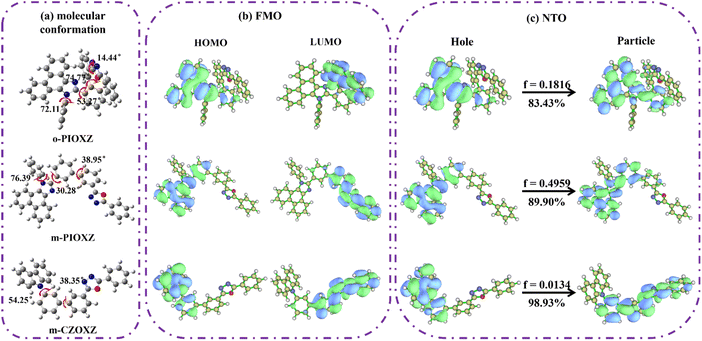 |
| | Fig. 2 (a) The geometries and structural formulae, (b) the frontier orbital distribution, and (c) the S0 → S1 natural transition orbital (NTO) of the three materials. | |
Photophysical properties
The UV-vis absorption and photoluminescence (PL) spectra of the three materials in diluted THF (10−5 mol L−1) and neat films at room temperature are shown in Fig. 3 and Table 1. The maximum absorption peaks of o-PIOXZ and m-PIOXZ are around 260 nm, attributed to the phenanthroimidazole absorption. Besides this, o-PIOXZ possesses a shoulder peak at about 288 nm, which can be attributed to the CT absorption, while m-PIOXZ does not show this shoulder peak due to the meta-linkage enhanced conjugation. However, despite the similar meta-linkage, m-CZOXZ shows a similar CT-like wide absorption band to o-PIOXZ at 287 nm, revealing that the stronger donor ability of carbazole can also contribute to the formation of the CT excited state. Notably, m-CZOXZ also shows vibrational fine structure in PL spectra in low polarity solvents, indicating the hybridization of LE and CT excited state components. The corresponding Lippert–Mataga solvatochromic models of the three materials further reveal their distinct excited state properties, as shown in Fig. 4. The excited-state dipole moment (μe) of the LE-like m-PIOXZ is only 5.39 Debye, while the CT-like o-PIOXZ shows a large μe of 15 Debye in high polarity solvents. Interestingly, m-CZOXZ shows a very large μe of 35 Debye in high polarity solvents, while in lower polarity solvents, the μe falls to only 7 Debye, which can be assigned to the activated through-space CT in high polarity solvents, as the meta-linkage is not conjugate bonding. As a result, the neat film of m-PIOXZ shows the highest photoluminescence quantum yield (PLQY) of over 40% among the three materials, showing great potential in non-doped OLEDs. Additionally, the phosphorescent emissions of the three materials are also measured at nitrogen temperature with a delay time of 100 ms as shown in Fig. S17.† Thanks to the ultraviolet emission of the three materials, the T1 levels of the three materials are all over 2.7 eV, enabling their applications as efficient host materials for green and red phosphorescent materials. From the transient PL spectrum, it can be seen that all three materials exhibit nanosecond lifetimes, as shown in Fig. S18.†
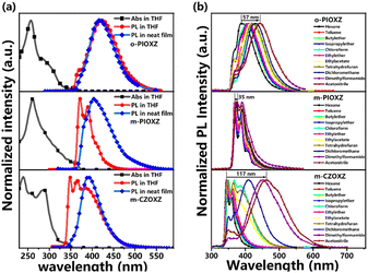 |
| | Fig. 3 (a) Normalized UV-vis absorption in THF solution (10−5 M) and normalized PL spectra in THF (10−5 M) and in the film state; (b) normalized PL spectra of the three materials in different solvents with increasing polarity. | |
 |
| | Fig. 4 The Lippert–Mataga solvatochromic model of (a) o-PIOXZ, (b) m-PIOXZ, and (c) m-CZOXZ. | |
Single crystal structures and molecular stacking patterns
The stacking pattern of organic materials is crucial for their OLED performances in terms of the light-outcoupling ability and carrier transportation ability, especially when the materials are used as the host materials in the emitter layer. In order to investigate the stacking pattern of the three materials, single crystal growth is carried out on them, and three single crystals with good quality are obtained. As shown in Fig. 5, first, the twisting angles of the three molecules in the single crystal are all decreased compared to their optimized conformations in a vacuum, revealing that the intermolecular interactions in the three single crystals can give rise to the regular face-to-face stacking, which is crucial for light out-coupling and efficient carrier transportation. For example, clear π stacking of phenanthroimidazole and oxadiazole can be found in o-PIOXZ and m-CZOXZ, respectively. However, this kind of stacking pattern is not an ideal one for the simultaneous transportation of holes and electrons: there is only donor (o-PIOXZ) or only acceptor (m-CZOXZ) packing in the single crystal, which may cause unbalanced transportation of holes and electrons in OLEDs. In contrast, the stacking pattern of m-PIOXZ is more ideal: both the donor phenanthroimidazole and the acceptor oxadiazole show clear π stacking. The formation of the ideal stacking can be understood by the relatively smaller bond twisting (approximately 39°, 23° and 19° for the marked bonds in Fig. 5b). We then fabricated the hole-only and electron-only devices for the three materials and investigated their carrier mobilities. As depicted in Fig. 6 and Table 2, m-PIOXZ shows the highest carrier mobilities (hole and electron mobilities of 5.1 × 10⁻⁶ and 1.3 × 10⁻⁵ cm2 V−1 s−1, respectively). These values are also comparable to those of the traditional host or transportation materials such as CBP and mCP, which is in accordance with their regular, head-to-head stacking patterns. Notably, although balanced carrier transportation is not obtained in the other two materials, relatively high hole transportation (o-PIOXZ) and electron transportation (m-CZOXZ) are also obtained, corresponding to their regular face-to-face donor and acceptor stacking, respectively.
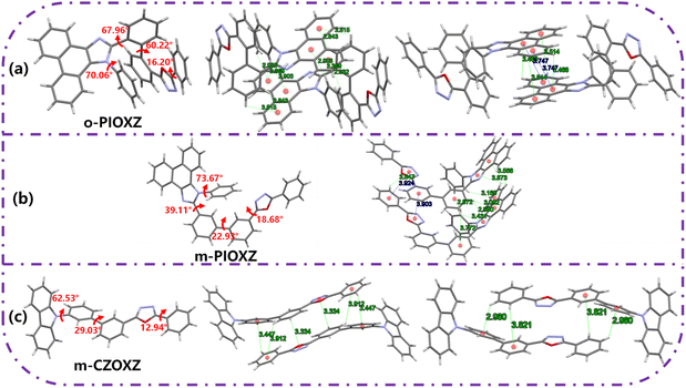 |
| | Fig. 5 The molecular stacking patterns and single crystal structures with torsion angles of (a) m-PIOXZ, (b) o-PIOXZ and (c) m-CZOXZ. | |
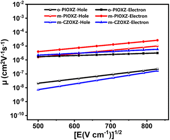 |
| | Fig. 6 Electron field intensity–mobility curves. The hole-only device structure is ITO/HATCN (10 nm)/m-PIOXZ or o-PIOXZ or m-CZOXZ (80 nm)/HATCN (10 nm)/Al (100 nm), and the electron-only device structure is ITO/LiF (1 nm)/TPBi (10 nm)/m-PIOXZ, o-PIOXZ, m-CZOXZ (80 nm)/LiF (1 nm)/Al (100 nm). | |
Table 2 The carrier mobility of the three materials under an electric field of 5.0 × 10⁵ V cm−1
| Compounds |
Hole mobility [cm2 V−1 s−1] |
Electron mobility [cm2 V−1 s−1] |
| o-PIOXZ |
9.3 × 10⁻⁸ |
2.5 × 10⁻⁶ |
| m-PIOXZ |
5.1 × 10⁻⁶ |
1.3 × 10⁻⁵ |
| m-CZOXZ |
5.2 × 10⁻⁸ |
4.7 × 10⁻⁶ |
Electroluminescence performances
The electroluminescence performance of these three molecules as the EML in non-doped OLEDs was initially studied. The device structure was designed as follows: ITO/HATCN (20 nm)/TAPC (40 nm)/TCTA (5 nm)/mCP (5 nm)/EML (20 nm)/TPBi (35 nm)/LiF (1.5 nm)/Al (100 nm). Among them, ITO is used as the anode; HATCN (1,4,5,8,9,11-hexaazatriphenylenehexacarbonitrile) serves as the hole injection layer; TAPC (4,4′-cyclohexylidenebis[N,N-bis(p-tolyl)aniline]) and TCTA (4,4′,4′′-tris(carbazol-9-yl)-triphenylamine) function as the hole transport layers; mCP (1,3-bis(carbazol-9-yl)benzene) acts as the electron blocking layer; TPBi (2,2′,2"-(1,3,5-benzinetriyl)-tris(1-phenyl-1-H-benzimidazole)) is used as both the electron transport layer and hole injection layer; LiF is used as the electron injection layer. The chemical structures and HOMO/LUMO energy levels of the different layers of the device are shown in Fig. 7. The data are summarized in Table 3.
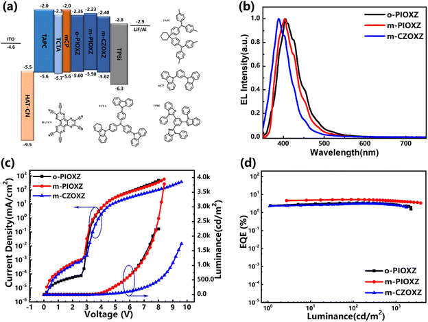 |
| | Fig. 7 (a) Energy level diagrams; (b) EL spectra; (c) luminance–voltage–current density curves of non-doped OLEDs; and (d) external quantum efficiency–luminance curves. | |
Table 3 EL data of non-doped ultraviolet fluorescent OLEDs
| Emitters |
Vona [V] |
Lmaxb [cd m−2] |
CEmaxc [cd A−1] |
PEmaxd [lm W−1] |
EQEmaxe [%] |
λELf [nm] |
CIE (x, y)g |
| Von = turn-on voltage at 1 cd m2. Lmax = maximum luminance. CEmax = maximum current efficiency. PEmax = maximum power efficiency. EQEmax = maximum external quantum efficiency. λEL = peak of the electroluminescence spectrum. CIE = CIE coordinates recorded at EQEmax. |
| o-PIOXZ |
3.2 |
2244 |
1.06 |
0.84 |
3.40 |
405 |
(0.161, 0.056) |
| m-PIXOZ |
3.2 |
3782 |
1.08 |
0.99 |
5.23 |
404 |
(0.160, 0.045) |
| m-CZOXZ |
3.6 |
1739 |
0.50 |
0.28 |
3.15 |
389 |
(0.166, 0.047) |
First, all three devices show electroluminescence at around 400 nm, which is similar to their neat films and meets the demand of near-ultraviolet emission, revealing that the device structures are reasonable. Among the three non-doped OLEDs, m-PIOXZ exhibits the highest EQE of 5.23%, which is among the best results for non-doped ultraviolet OLEDs. This result can be first assigned to the balanced carrier mobilities of m-PIOXZ, which can be understood by the increased turn-on voltage of the m-CZOXZ non-doped OLED. Next, although m-PIOXZ is a LE material, the PLQY of m-PIOXZ is twice that of o-PIOXZ and m-CZOXZ (Table 1), which is also a key reason for the high EQE.
The simultaneously realized good hole and electron mobilities and the reasonable triplet energy level of m-PIOXZ further motivate us to investigate its application as an efficient host for phosphorescent OLEDs (PhOLEDs). The PhOLEDs were constructed using Ir(ppy)2acac (bis[2-(2-pyridinyl-N)phenyl-C](acetylacetonato)iridium(III)), PO-01 (Iridium(III) bis(4-phenylthieno[3,2-c]pyridinato-N,C2′)acetylacetonate), and Ir(MDQ)2acac (bis(2-methyldibenzo[f,h]quinoxaline)(acetylacetonate)iridium(III)) as phosphorescent dopants for green, yellow, and red emission, respectively. The device structure of the PhOLED involves changing the EML in the undoped device to host: x wt% guest (where x = 8 for green and x = 3 for yellow and red). The test results are summarized in Fig. 8 and Table 4. We also fabricated the PhOLED using o-PIOXZ and m-CZOXZ as hosts for reference. First, as shown in Table 4, the turn-on voltage of the PhOLED with m-PIOXZ and o-PIOXZ as the host is lower than that of the doped devices with m-CZOXZ as the host, which is similar to those of their non-doped devices. Notably, the turn-on voltages of all PhOLEDs are lower than those of their non-doped OLEDs, especially, the turn-on voltages of PhOLEDs related to m-PIOXZ are all as low as 2.8 V. More importantly, all three materials show efficient energy transfer to the phosphorescent guests in all PhOLEDs, revealing their abilities as host materials. (Fig. S20†).
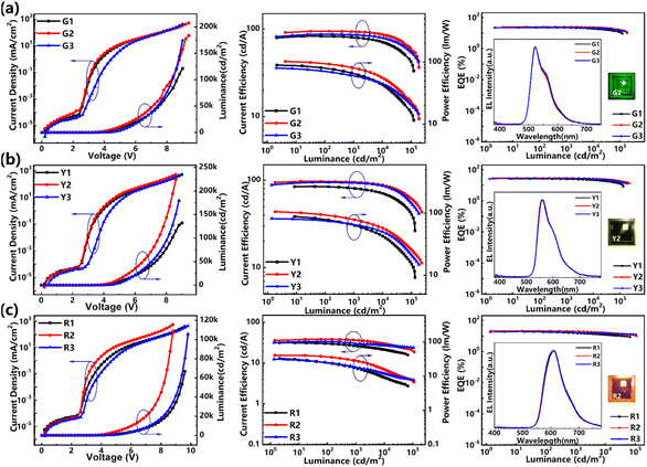 |
| | Fig. 8 The current density–voltage–luminance curves, current efficiency–luminance–power efficiency curves, and EQE–luminance curves (inset: the EL spectrum and photograph of the operating devices) of the doped devices with (a–c) are green, yellow, and red PhOLEDs, respectively. o-PIOXZ, m-PIOXZ, and m-CZOXZ are the host materials for G1, G2, and G3, R1, R2, and R3, and Y1, Y2, and Y3 devices, respectively. | |
Table 4 EL performance of PHOLEDs based on m-PIOXZ, o-PIOXZ, and m-CZOXZ hosts
| Devicesa |
Vonb [V] |
Lmaxc [cd m−2] |
CEmaxd [cd A−1] |
PEmaxe [lm W−1] |
EQEmaxf [%] |
EQEroll-offg [%] |
λELh [nm] |
CIEi (x, y) |
| o-PIOXZ, m-PIOXZ, and m-CZOXZ are the host materials for G1, G2, and G3, Y1, Y2, and Y3, and R1, R2, and R3 devices, respectively. Von = turn-on voltage at 1 cd m−2. Lmax = maximum luminance. CEmax = maximum current efficiency. PEmax = maximum power efficiency. EQEmax = maximum external quantum efficiency. EQEroll-off = external quantum efficiency roll-off from the maximum value to 1000 cd m−2. λEL = peak of the electroluminescence spectrum. CIE = CIE coordinates recorded at EQEmax. |
| G1 |
2.8 |
121![[thin space (1/6-em)]](https://www.rsc.org/images/entities/char_2009.gif) 192 192 |
82.68 |
89.07 |
22.29 |
3.05 |
524 |
(0.33, 0.62) |
| G2 |
2.8 |
184![[thin space (1/6-em)]](https://www.rsc.org/images/entities/char_2009.gif) 047 047 |
94.44 |
102.34 |
25.20 |
1.15 |
523 |
(0.32, 0.63) |
| G3 |
3.2 |
174![[thin space (1/6-em)]](https://www.rsc.org/images/entities/char_2009.gif) 659 659 |
87.18 |
80.25 |
23.27 |
1.49 |
523 |
(0.32, 0.62) |
| Y1 |
3.0 |
132![[thin space (1/6-em)]](https://www.rsc.org/images/entities/char_2009.gif) 085 085 |
84.61 |
88.34 |
25.99 |
5.40 |
562 |
(0.48, 0.51) |
| Y2 |
2.8 |
224![[thin space (1/6-em)]](https://www.rsc.org/images/entities/char_2009.gif) 515 515 |
96.91 |
105.63 |
29.61 |
2.36 |
561 |
(0.48, 0.51) |
| Y3 |
3.4 |
179![[thin space (1/6-em)]](https://www.rsc.org/images/entities/char_2009.gif) 917 917 |
94.54 |
81.60 |
28.64 |
2.56 |
559 |
(0.47, 0.51) |
| R1 |
3.0 |
66![[thin space (1/6-em)]](https://www.rsc.org/images/entities/char_2009.gif) 851 851 |
31.72 |
33.20 |
19.03 |
20.69 |
612 |
(0.61, 0.38) |
| R2 |
2.8 |
108![[thin space (1/6-em)]](https://www.rsc.org/images/entities/char_2009.gif) 781 781 |
38.78 |
40.71 |
21.38 |
6.87 |
608 |
(0.60, 0.39) |
| R3 |
3.2 |
105![[thin space (1/6-em)]](https://www.rsc.org/images/entities/char_2009.gif) 826 826 |
33.91 |
31.52 |
18.88 |
13.75 |
607 |
(0.60, 0.39) |
Compared to the other two materials, m-PIOXZ possesses the best PhOLED performance, due to its satisfactory and balanced carrier mobilities. For example, the Lmax, CEmax and PEmax of the green-doped device G2 reach 184![[thin space (1/6-em)]](https://www.rsc.org/images/entities/char_2009.gif) 047 cd m−2, 94.44 cd A−1 and 102.34 lm W−1, respectively; and the EQEmax reaches 25.20%, which are excellent results compared to the previous reports.22,28,35,43–46 More importantly, the efficiency roll-off at 1000 cd m−2 of G2 is only 1.15% and the roll-off at 5000 cd m−2 is only 4.81%, revealing that the device stability using m-PIOXZ is expectable. The performance of PhOLEDs with these three molecules as host materials is better than that of traditional commercial host materials, such as CBP and mCP. The data are summarized in Fig. S21, S22, and Table S2.† Therefore, we further estimated the OLED operational lifetime of the G2 device. As shown in Fig. S23 and Table S1,† the operational lifetime of the G2 device reaches LT50 = 67.75 h at a luminance of 3548 cd m−2 without encapsulation, corresponding to a 583 h lifetime at an initial luminance of 1000 cd m−2, which is also a good result compared to the previous reports. Notably, not only the green OLED but also the yellow and red OLED Y2 and R2 using m-PIOXZ as host materials also obtain competitive performances in terms of the device efficiency, efficiency roll-off and operational lifetime. Last but not least, although m-PIOXZ is a LE molecule, the separated HOMOs/LUMOs and the effective stacking mode create a good hole–electron transport channel, balancing the carrier transport rate and facilitating efficient recombination of holes and electrons, which improves EL efficiency and reduces efficiency roll-off.
047 cd m−2, 94.44 cd A−1 and 102.34 lm W−1, respectively; and the EQEmax reaches 25.20%, which are excellent results compared to the previous reports.22,28,35,43–46 More importantly, the efficiency roll-off at 1000 cd m−2 of G2 is only 1.15% and the roll-off at 5000 cd m−2 is only 4.81%, revealing that the device stability using m-PIOXZ is expectable. The performance of PhOLEDs with these three molecules as host materials is better than that of traditional commercial host materials, such as CBP and mCP. The data are summarized in Fig. S21, S22, and Table S2.† Therefore, we further estimated the OLED operational lifetime of the G2 device. As shown in Fig. S23 and Table S1,† the operational lifetime of the G2 device reaches LT50 = 67.75 h at a luminance of 3548 cd m−2 without encapsulation, corresponding to a 583 h lifetime at an initial luminance of 1000 cd m−2, which is also a good result compared to the previous reports. Notably, not only the green OLED but also the yellow and red OLED Y2 and R2 using m-PIOXZ as host materials also obtain competitive performances in terms of the device efficiency, efficiency roll-off and operational lifetime. Last but not least, although m-PIOXZ is a LE molecule, the separated HOMOs/LUMOs and the effective stacking mode create a good hole–electron transport channel, balancing the carrier transport rate and facilitating efficient recombination of holes and electrons, which improves EL efficiency and reduces efficiency roll-off.
Conclusion
In conclusion, three types of ultraviolet to deep-blue emissive molecules were synthesized and characterized. The donor–acceptor structure of these materials enables their dual functionality as ultraviolet-emitting materials and efficient hosts for phosphorescent dopants, particularly the meta-linked material m-PIOXZ. Green, yellow, and red PhOLEDs utilizing m-PIOXZ as the host achieve high efficiencies with EQEmax exceeding 20% (low efficiency roll-off) and exhibit extended operational lifetimes, outperforming commercial host materials. These results highlight the significant potential of m-PIOXZ for practical applications.
Data availability
The data supporting this article have been included as part of the ESI.† Additional data are available from the corresponding author upon reasonable request.
Author contributions
L. Chu synthesized the materials, characterized their basic properties, performed data processing and analysis, and wrote the manuscript. C. Ma carried out the fabrication and characterization studies of the devices. L. Zhang, Y. Zhou, J. Song, and Q. Sun conducted data verification, reviewed and revised the article, and supervised the work. S.-T. Zhang supported the theoretical calculations. W. Yang provided financial support and supervised the work. S. Xue provided financial support, conceived the idea, and reviewed and edited the article.
Conflicts of interest
The authors declare that they have no conflict of interest.
Acknowledgements
This work was supported by the National Natural Science Foundation of China (No. 51873095 and 52273183), the Taishan Scholar Constructive Engineering Foundation of Shandong Province of China (No. tsqn202211164), and the Natural Science Foundation of Qingdao City of China (No. 23-2-1-239-zyyd-jch). We also thank the Open Project of the State Key Laboratory of Supramolecular Structure and Materials of Jilin University (sklssm2024032).
Notes and references
- C. W. Tang and S. A. VanSlyke, Appl. Phys. Lett., 1987, 51, 913–915 CrossRef CAS.
- Y. Xu, P. Xu, D. Hu and Y. Ma, Chem. Soc. Rev., 2021, 50, 1030–1069 RSC.
- P. Han, C. Lin, E. Xia, J. Cheng, Q. Xia, D. Yang, A. Qin, D. Ma and B. Z. Tang, Angew. Chem., Int. Ed., 2023, 62, e202310388 CrossRef CAS.
- U. Deori, G. P. Nanda, C. Murawski and P. Rajamalli, Chem. Sci., 2024, 15, 17739–17759 RSC.
- J. Lou, G. Li, X. Guo, B. Li, D. Yang, H. Zhang, Z. Wang and B. Z. Tang, Small, 2024, 20, 2308468 CrossRef CAS PubMed.
- H. Liu, Q. Bai, L. Yao, H. Zhang, H. Xu, S. Zhang, W. Li, Y. Gao, J. Li, P. Lu, H. Wang, B. Yang and Y. Ma, Chem. Sci., 2015, 6, 3797–3804 RSC.
- X. He, J. Lou, B. Li, X. Dong, F. Zhong, W. Liu, X. Feng, D. Yang, D. Ma, Z. Zhao, Z. Wang and B. Z. Tang, Adv. Mater., 2024, 36, 2310417 CrossRef CAS PubMed.
- X. Guo, G. Li, J. Lou, K. Chen, R. Huang, D. Yang, H. Zhang, Z. Wang and B. Z. Tang, Small, 2022, 18, 2204029 CrossRef CAS PubMed.
- B. Li, J. Lou, H. Zhang, G. Li, X. He, Y. Huang, N. Zheng, Z. Wang, D. Ma and B. Z. Tang, Adv. Funct. Mater., 2023, 33, 2212876 CrossRef CAS.
- P. Ma, Y. Chen, Y. Man, Q. Qi, Y. Guo, H. Wang, Z. Li, P. Chang, C. Qu, C. Han and H. Xu, Angew. Chem., Int. Ed., 2024, 63, e202316479 CrossRef CAS.
- Y. Luo, S. Li, Y. Zhao, C. Li, Z. Pang, Y. Huang, M. Yang, L. Zhou, X. Zheng, X. Pu and Z. Lu, Adv. Mater., 2020, 32, 2001248 CrossRef CAS PubMed.
- S. Liu, X. Zhang, C. Ou, S. Wang, X. Yang, X. Zhou, B. Mi, D. Cao and Z. Gao, ACS Appl. Mater. Interfaces, 2017, 9, 26242–26251 CrossRef CAS.
- S.-L. Lin, L.-H. Chan, R.-H. Lee, M.-Y. Yen, W.-J. Kuo, C.-T. Chen and R.-J. Jeng, Adv. Mater., 2008, 20, 3947–3952 CrossRef CAS.
- Q. Li, Y. Guo, J. Lan, Y. Yang, D. Wu and Z. Bin, Chem. Sci., 2024, 15, 16096–16102 RSC.
- K. E. Linton, A. L. Fisher, C. Pearson, M. A. Fox, L.-O. Pålsson, M. R. Bryce and M. C. Petty, J. Mater. Chem., 2012, 22, 11816–11825 RSC.
- Y. Jia, Y. Zhang, S. Fan, S. Wu, X. Zhao, S. Wang and X. Li, Org. Electron., 2019, 64, 259–265 CrossRef CAS.
- H. Zhou, R. Wang, M. Sun, Y. Zhou, L. Zhang, J. Song, Q. Sun, S.-T. Zhang, W. Yang and S. Xue, Chem. Sci., 2024, 15, 18601–18607 RSC.
- H. Zhang, B. Zhang, Y. Zhang, Z. Xu, H. Wu, P.-A. Yin, Z. Wang, Z. Zhao, D. Ma and B. Z. Tang, Adv. Funct. Mater., 2020, 30, 2002323 CrossRef CAS.
- Z. Zhong, X. Zhu, X. Wang, Y. Zheng, S. Geng, Z. Zhou, X. J. Feng, Z. Zhao and H. Lu, Adv. Funct. Mater., 2022, 32, 2112969 CrossRef CAS.
- C. Du, H. Liu, Z. Cheng, S. Zhang, Z. Qu, D. Yang, X. Qiao, Z. Zhao and P. Lu, Adv. Funct. Mater., 2023, 33, 2304854 CrossRef CAS.
- X. Zhan, Z. Wu, Y. Lin, Y. Xie, Q. Peng, Q. Li, D. Ma and Z. Li, Chem. Sci., 2016, 7, 4355–4363 RSC.
- J. Xu, H. Liu, J. Li, Z. Zhao and B. Z. Tang, Adv. Opt. Mater., 2021, 9, 2001840 CrossRef CAS.
- C. Han, Z. Zhang, H. Xu, J. Li, G. Xie, R. Chen, Y. Zhao and W. Huang, Angew. Chem., Int. Ed., 2012, 51, 10104–10108 CrossRef CAS.
- W. Zhang, J. Yu, Q. Cao, Y. Qian, J. Wang, C. Yang, H. Zhuang, W. Bian, Y. Xin and X. Ban, J. Mater. Chem. C, 2023, 11, 16247–16257 RSC.
- M.-H. Tsai, Y.-H. Hong, C.-H. Chang, H.-C. Su, C.-C. Wu, A. Matoliukstyte, J. Simokaitiene, S. Grigalevicius, J. V. Grazulevicius and C.-P. Hsu, Adv. Mater., 2007, 19, 862–866 CrossRef CAS.
- Y. Tao, C. Yang and J. Qin, Chem. Soc. Rev., 2011, 40, 2943–2970 RSC.
- X. Yang, G. Zhou and W.-Y. Wong, Chem. Soc. Rev., 2015, 44, 8484–8575 RSC.
- C. Liu, T. Li, M. Sun, M. Xie, Y. Zhou, W. Feng, Q. Sun, S.-T. Zhang, S. Xue and W. Yang, Adv. Funct. Mater., 2023, 33, 2215066 CrossRef CAS.
- G.-X. Yang, J.-J. Zhu, S.-S. Tang, H.-J. Tan, X. He, J.-X. Jian, X.-H. Zheng and Q.-X. Tong, Adv. Photonics Res., 2021, 2, 2100031 CrossRef CAS.
- W. Cui, C. Liu, X. Chao, M. Xie, Q. Sun, D. Liu, Y. Pan, S.-T. Zhang, S. Xue and W. Yang, Adv. Opt. Mater., 2023, 11, 2202947 CrossRef CAS.
- P. Yu and Y. Xiao, Materials, 2021, 14, 2349 CrossRef CAS PubMed.
- M. Sun, C. Ma, M. Xie, L. Chu, X. Wang, Q. Sun, W. Yang and S. Xue, Org. Chem. Front., 2023, 10, 4878–4886 RSC.
- D. Sylvinson, H.-F. Chen, L. M. Martin, P. J. G. Saris and M. E. Thompson, ACS Appl. Mater. Interfaces, 2019, 11, 5276–5288 CrossRef PubMed.
- W.-C. Chen, Y. Yuan, S.-F. Ni, Q.-X. Tong, F.-L. Wong and C.-S. Lee, Chem. Sci., 2017, 8, 3599–3608 RSC.
- W. Ma, Z. Bin, G. Yang, J. Liu and J. You, Angew. Chem., Int. Ed., 2022, 61, e202116681 CrossRef CAS.
- Q. Wang, F. Lucas, C. Quinton, Y.-K. Qu, J. Rault-Berthelot, O. Jeannin, S.-Y. Yang, F.-C. Kong, S. Kumar, L.-S. Liao, C. Poriel and Z.-Q. Jiang, Chem. Sci., 2020, 11, 4887–4894 RSC.
- H. Sasabe, N. Toyota, H. Nakanishi, T. Ishizaka, Y.-J. Pu and J. Kido, Adv. Mater., 2012, 24, 3212–3217 CrossRef CAS PubMed.
- N. A. Kukhta, T. Matulaitis, D. Volyniuk, K. Ivaniuk, P. Turyk, P. Stakhira, J. V. Grazulevicius and A. P. Monkman, J. Phys. Chem. Lett., 2017, 8, 6199–6205 CrossRef CAS PubMed.
- Y. Tan, Z. Wang, C. Wei, Z. Liu, Z. Bian and C. Huang, Org. Electron., 2019, 69, 77–84 CrossRef CAS.
- Y.-T. Chang, J.-K. Chang, Y.-T. Lee, P.-S. Wang, J.-L. Wu, C.-C. Hsu, I.-W. Wu, W.-H. Tseng, T.-W. Pi, C.-T. Chen and C.-I. Wu, ACS Appl. Mater. Interfaces, 2013, 5, 10614–10622 CrossRef CAS.
- T. Lu and F. Chen, J. Comput. Chem., 2012, 33, 580–592 CrossRef CAS PubMed.
- T. Lu and Q. Chen, Chem. Methods, 2021, 1, 231–239 CrossRef CAS.
- B. Wang, X. Lv, J. Tan, Q. Zhang, Z. Huang, W. Yi and L. Wang, J. Mater. Chem. C, 2016, 4, 8473–8482 RSC.
- B. Patil, J. Lade, S.-S. Chiou, Y.-C. Cheng, Y.-F. Lin, Y. Jadhav, P. Chetti, C.-H. Chang and A. Chaskar, Org. Electron., 2021, 92, 106090 CrossRef CAS.
- B. Sun, K.-N. Tong, S.-N. Liu, M.-K. Fung and J. Fan, J. Mater. Chem. C, 2021, 9, 2969–2976 RSC.
- B. Sun, K.-N. Tong, X. Chen, J.-L. He, H. Liu, M.-K. Fung and J. Fan, J. Mater. Chem. C, 2021, 9, 7706–7712 RSC.
Footnote |
| † Electronic supplementary information (ESI) available: General methods, detailed thermal properties, CV curves, compound syntheses and characterization, other theoretical calculations, spectra, crystallographic data, other device performances, etc. CCDC 2410469, 2410470 and 2413461. For ESI and crystallographic data in CIF or other electronic format see DOI: https://doi.org/10.1039/d5sc00374a |
|
| This journal is © The Royal Society of Chemistry 2025 |
Click here to see how this site uses Cookies. View our privacy policy here.  Open Access Article
 a and
Shanfeng Xue
 *a
*a


![[thin space (1/6-em)]](https://www.rsc.org/images/entities/char_2009.gif) 192
192![[thin space (1/6-em)]](https://www.rsc.org/images/entities/char_2009.gif) 047
047![[thin space (1/6-em)]](https://www.rsc.org/images/entities/char_2009.gif) 659
659![[thin space (1/6-em)]](https://www.rsc.org/images/entities/char_2009.gif) 085
085![[thin space (1/6-em)]](https://www.rsc.org/images/entities/char_2009.gif) 515
515![[thin space (1/6-em)]](https://www.rsc.org/images/entities/char_2009.gif) 917
917![[thin space (1/6-em)]](https://www.rsc.org/images/entities/char_2009.gif) 851
851![[thin space (1/6-em)]](https://www.rsc.org/images/entities/char_2009.gif) 781
781![[thin space (1/6-em)]](https://www.rsc.org/images/entities/char_2009.gif) 826
826![[thin space (1/6-em)]](https://www.rsc.org/images/entities/char_2009.gif) 047 cd m−2, 94.44 cd A−1 and 102.34 lm W−1, respectively; and the EQEmax reaches 25.20%, which are excellent results compared to the previous reports.22,28,35,43–46 More importantly, the efficiency roll-off at 1000 cd m−2 of G2 is only 1.15% and the roll-off at 5000 cd m−2 is only 4.81%, revealing that the device stability using m-PIOXZ is expectable. The performance of PhOLEDs with these three molecules as host materials is better than that of traditional commercial host materials, such as CBP and mCP. The data are summarized in Fig. S21, S22, and Table S2.† Therefore, we further estimated the OLED operational lifetime of the G2 device. As shown in Fig. S23 and Table S1,† the operational lifetime of the G2 device reaches LT50 = 67.75 h at a luminance of 3548 cd m−2 without encapsulation, corresponding to a 583 h lifetime at an initial luminance of 1000 cd m−2, which is also a good result compared to the previous reports. Notably, not only the green OLED but also the yellow and red OLED Y2 and R2 using m-PIOXZ as host materials also obtain competitive performances in terms of the device efficiency, efficiency roll-off and operational lifetime. Last but not least, although m-PIOXZ is a LE molecule, the separated HOMOs/LUMOs and the effective stacking mode create a good hole–electron transport channel, balancing the carrier transport rate and facilitating efficient recombination of holes and electrons, which improves EL efficiency and reduces efficiency roll-off.
047 cd m−2, 94.44 cd A−1 and 102.34 lm W−1, respectively; and the EQEmax reaches 25.20%, which are excellent results compared to the previous reports.22,28,35,43–46 More importantly, the efficiency roll-off at 1000 cd m−2 of G2 is only 1.15% and the roll-off at 5000 cd m−2 is only 4.81%, revealing that the device stability using m-PIOXZ is expectable. The performance of PhOLEDs with these three molecules as host materials is better than that of traditional commercial host materials, such as CBP and mCP. The data are summarized in Fig. S21, S22, and Table S2.† Therefore, we further estimated the OLED operational lifetime of the G2 device. As shown in Fig. S23 and Table S1,† the operational lifetime of the G2 device reaches LT50 = 67.75 h at a luminance of 3548 cd m−2 without encapsulation, corresponding to a 583 h lifetime at an initial luminance of 1000 cd m−2, which is also a good result compared to the previous reports. Notably, not only the green OLED but also the yellow and red OLED Y2 and R2 using m-PIOXZ as host materials also obtain competitive performances in terms of the device efficiency, efficiency roll-off and operational lifetime. Last but not least, although m-PIOXZ is a LE molecule, the separated HOMOs/LUMOs and the effective stacking mode create a good hole–electron transport channel, balancing the carrier transport rate and facilitating efficient recombination of holes and electrons, which improves EL efficiency and reduces efficiency roll-off.


