2D Ti3C2Tx–xGnP incorporating PVDF/PMMA blend composites for dielectric capacitors
Received
18th October 2024
, Accepted 7th January 2025
First published on 22nd January 2025
Abstract
A comprehensive study of the dielectric and ferroelectric characteristics of polymer composites of xGnP–MXene hybrids (GMHs) in PVDF/PMMA blend films made via a solution casting method is reported. In the present study, we processed a flexible dielectric material by utilizing xGnP–MXene hybrids (GMHs) in a PVDF/PMMA blend. The heterogeneous polymer–polymer and polymer–GMH interactions in these hybrid nanocomposites (HNCs), as well as the composition-dependent crystal phases of the PVDF, were validated by the structural and morphological characteristics. The permittivity and AC conductivity of a composite containing 15 wt% hybrids are 157.4 and 8.04 × 10⁻⁸ S cm−1 at 100 Hz, respectively. These values are 15 times and 5 orders of magnitude greater than those of the pure blend. Thermal analysis showed 13.59% crystallinity for 15 wt% HNCs. The maximum energy density of the 15 wt% HNC is 2.78 J cm−3, and its power density is 12.12 MW cm−3. An excellent balance of dielectric properties was accomplished by combining Ti3C2Tx and xGnP in a suitable (1![[thin space (1/6-em)]](https://www.rsc.org/images/entities/char_2009.gif) :1 wt%) ratio. The processed materials are particularly effective in flexible microelectronic devices and are especially efficient at storing energy in dielectric capacitors.
:1 wt%) ratio. The processed materials are particularly effective in flexible microelectronic devices and are especially efficient at storing energy in dielectric capacitors.
1. Introduction
Electric power storage using dielectric materials is crucial to electronic and power generation systems, such as capacitors, automobiles, green energy production, medical equipment, and converter systems. Dielectric materials must have considerable dielectric permittivity and significant breakdown intensities in order to withstand the polarization caused by electric fields, which is required for the storage of electrical energy. The polarization of the dielectric material in an electric field and the applied electric field control the amount of energy stored in a capacitor. The charged energy density of the non-linear dielectric material can be written as,| | 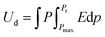 | (1) |
where applied electric field, saturation polarization, and remnant polarization are represented by the letters E, Pm, and Pr, respectively. Furthermore, the linear dielectric formula can be expressed as,| |  | (2) |
where εr and ε0 denote the relative dielectric constant and the vacuum dielectric constant respectively. Several investigations of binary polymer blends including crystalline polymers have been conducted in this context, and they are receiving a lot of attention from the scientific and business communities. For instance, protective films or coating materials made up of fluoropolymers are well recognized for their exceptional protective qualities.1 The characteristics of miscibility of blends generally connect two polymer components and have attracted a lot of attention among polymer blends. It has been widely researched that poly(vinylidene fluoride)/poly(methyl methacrylate), or PVDF/PMMA, is a common miscible blend.2 The blended PVDF and PMMA showed good miscibility over their whole composition range because of the double-bonded oxygen of the carbonyl group of the PMMA monomer unit, which significantly interacts with the acidic hydrogen of the CH2–CF2 monomer unit of PVDF. PVDF has strong mechanical, chemical, oxidation, and UV resistance, as well as thermal stability, and other qualities. It has the molecular formula (CH2–CF2) n, can be cast in a variety of polymorphs, including polar β, γ, and δ and non-polar α and ε phases.3,4 Due to the trans-planar zigzag shape, the β-phase exhibits the highest spontaneous polarization. The net dipole moment of the β-phase is generally higher in comparison to α and γ-phases. There are several studies in the literature on the creation of the electroactive β-phase using high voltage poling5 and mechanical stretching at high temperatures.6 PVDF is a multifunctional polymer that displays a number of significant characteristics, including ferroelectricity, pyroelectricity, and piezoelectricity. These behaviors are mostly exhibited when the polymer forms the polar β-phase.7,8 PMMA is a clear amorphous polymer that is frequently utilized in thermoplastic substances due to its transparency, impact resistance, and production simplicity. Neat polymers have very low relative permittivity so it is important to enhance the dielectric properties as much as possible so that conducting composites or blends are benefited. The insulating polymer matrix is accommodated by the conducting nanofillers through the incorporation of graphene,9 carbon nanotubes (CNT),10 graphene oxide (GO),11 graphite nano-platelets (GNPs),12 MXene (Ti3C2TX)13etc. The outstanding functional features, vast surface areas, and electrical and mechanical properties of the above 2D materials have attracted great attention in recent years.
Exfoliated graphite nano-platelets (xGnP) are made by using a variety of chemical and mechanical exfoliation procedures from graphene. These are being added to polymer blends to increase the strength, stiffness, durability, and hardness of composites as well as electrical conductivity and also have improved applications in the automotive and aerospace sectors. In addition to carbon nanoparticles, a brand new class of two-dimensional materials known as MXenes has recently shown exceptional dielectric characteristics in the polymer matrix. MXenes have the universal formula MnXn−1Tx, where ‘M’ represents early transition metals (such as Sc, Ti, Zr, Hf, V, Nb, Ta, Cr, Mo, and others), ‘X’ denotes C or N components, Tx stands for the surface terminations on the outer layer, such as –OH, –O, or –F, and ‘n’ is 1, 2, 3… up to n.14 They have shown themselves as nanofillers for blend matrices to successfully boost their permittivity because of their strong electrical conductivity.15,16 The dielectric characteristics of the composites are significantly influenced by the uniformity of the filler in the polymer matrix. It is difficult to fill the interlayer gap of layered-shaped MXene with a polymer, so intercalation can improve accessibility to the inner-layer sheets.17 Functional groups like carboxyls, –F, –O or –OH found in MXenes can interact with the polymer matrix to improve interfacial interaction. The resulting hybrid maximizes filler–matrix compatibility and also reduces defects when combined with xGnPs. They have both high surface area and lightweight materials that perform better at lower filler loadings which is a crucial factor for lightweight composite applications. The hybrid can be easily functionalized by surface modification for energy storage applications.14–16 Numerous earlier studies have looked into incorporation of organic and inorganic fillers into the PVDF/PMMA matrix such as Ni–ZnO, AT–hBN, BFO–MgO, and BaTiO3–OMMT, which results in an exciting energy storage capacity that satisfies the high dielectric constant and energy storage density needed for high-performance capacitors.18–21 Dielectric and ferroelectric analysis of PVDF/PMMA composites by incorporating the two-dimensional xGnP–MXene dual filler has not been reported. This paper reports on the dielectric and ferroelectric analysis of PVDF/PMMA thin films that have been reinforced with GMHs for use as separators in energy storage devices.
2. Experimental section
2.1 Materials
PVDF, with an average molecular weight of approximately ∼1.8 × 10⁵ g mol−1, was purchased from Sigma-Aldrich. PMMA (HI Media Laboratories Pvt. Ltd) has an average molecular weight of ∼3.5 × 10⁵ g mol−1. We purchased concentrated hydrofluoric acid in the form of an aqueous HF solution (40.0%, AR grade) from Qixian Huihongyuan Chemical Co. Ltd (Shanxi, China). Exfoliated graphite nanoplatelets (xGnP-15) were purchased from XG Sciences USA. The Grade-C (surface area of 300 m2 g−1) xGnP utilized had an average thickness of 2 nm, diameter of less than 2 microns and a density of 2.2 g cm−3. The Ti3AlC2 MAX phase (98.0%, AR grade) was purchased from Jilin 11 Technology Co. Ltd (Changchun, China). PVDF and PMMA were all dissolved using 99.5% pure N,N-dimethylformamide (DMF) from Sigma-Aldrich.
2.2 Preparation of the 2D Ti3C2Tx MXene
The selective acid etching of Al atom layers from the Ti3AlC2 MAX phase was used to generate delaminated Ti3C2Tx MXene nanosheets. This was followed by ultrasonic exfoliation in DMSO. To begin with, 100 ml of a concentrated HF (40%) solution was mixed slowly with 10 g of MAX powder, and the mixture was magnetically stirred for 24 hours at 40 °C. The resultant mixture was repeatedly washed with deionized water and ethanol until a pH of 5–6 was achieved. After washing, 4 g of the as-prepared MXenes and 60 ml of DMSO were magnetically stirred for 4–5 hours at room temperature to delaminate the resulting multilayered flakes of MXene powder. The previously described washing methods were applied once again to ensure that all DMSO was eliminated from the MXenes. Ultimately, the resulting suspension was centrifuged for 20 minutes at 8000 rpm, washed with deionized water or ethanol, and dried in a vacuum oven. The delaminated MXene nanosheets were produced after drying.
2.3 Preparation of the PMMA/PVDF-GMHs nanocomposite
The two polymers were first dissolved in DMF separately before being combined to create the PMMA/PVDF mixture (50/50 ratio). The mixture was constantly stirred at room temperature for 2 h to create a homogeneous mixture. The 1:1 ratio of xGnP:Ti3C2Tx was arrived at as a result of experimental optimization, in which various ratios were examined in order to determine which composition offered the optimum combination. Then, xGnP & Ti3C2Tx powder was dissolved and suspended individually in DMF for 45 minutes and added to the homogeneous polymer blend. Several concentrations of nanofiller (2.5, 5.0, 7.5, 10, 15 and 20 wt%) were added to the composite mixture and sonicated for an additional 20 minutes in order to create a homogeneous distribution of filler in the blend matrix. The solution was then spread out over a glass plate to create uniformly thin HNCs. The film was dried in a vacuum oven at 80 °C for 8–10 hours.
2.4 Characterization of the sample
An XRD instrument, model: Rigaku Ultima IV, Japan was utilized for preliminary investigation. Using a Jasco FT-IR-4600 TYPE-A, FTIR spectra were obtained in the wave number range of 500 to 4000 cm−1 to investigate its structure. The interaction between the GMHs and polymer blend was examined using Raman spectroscopy (model: RENISHAW InVia Raman microscope). At room temperature, the microstructure study of the sample was carried out with a field emission scanning electron microscope (FE-SEM) (Carl Zeiss, model: EVO-18). The thermal analysis was performed using Differential Scanning Calorimetry (DSC 1-star Mettler Toledo) equipment, heating the sample at a rate of 10 °C min−1. An LCR meter (model: PSM-1735, LCR N4L, UK) was used to measure the dielectric characteristics in the 25–100 °C temperature range and the 100 Hz–1 MHz frequency range, respectively. An electrical impedance analyzer (Hioki-Impedance Analyzer IM3570) with a frequency range of 100 Hz to 5 MHz was used to assess the electrical impedance characteristics of the synthesized composites at 25 °C. A Marine India P–E loop tracer was used to measure the ferroelectricity of the sample at room temperature.
3. Results and discussion
3.1 Synthesized Ti3C2Tx characteristics
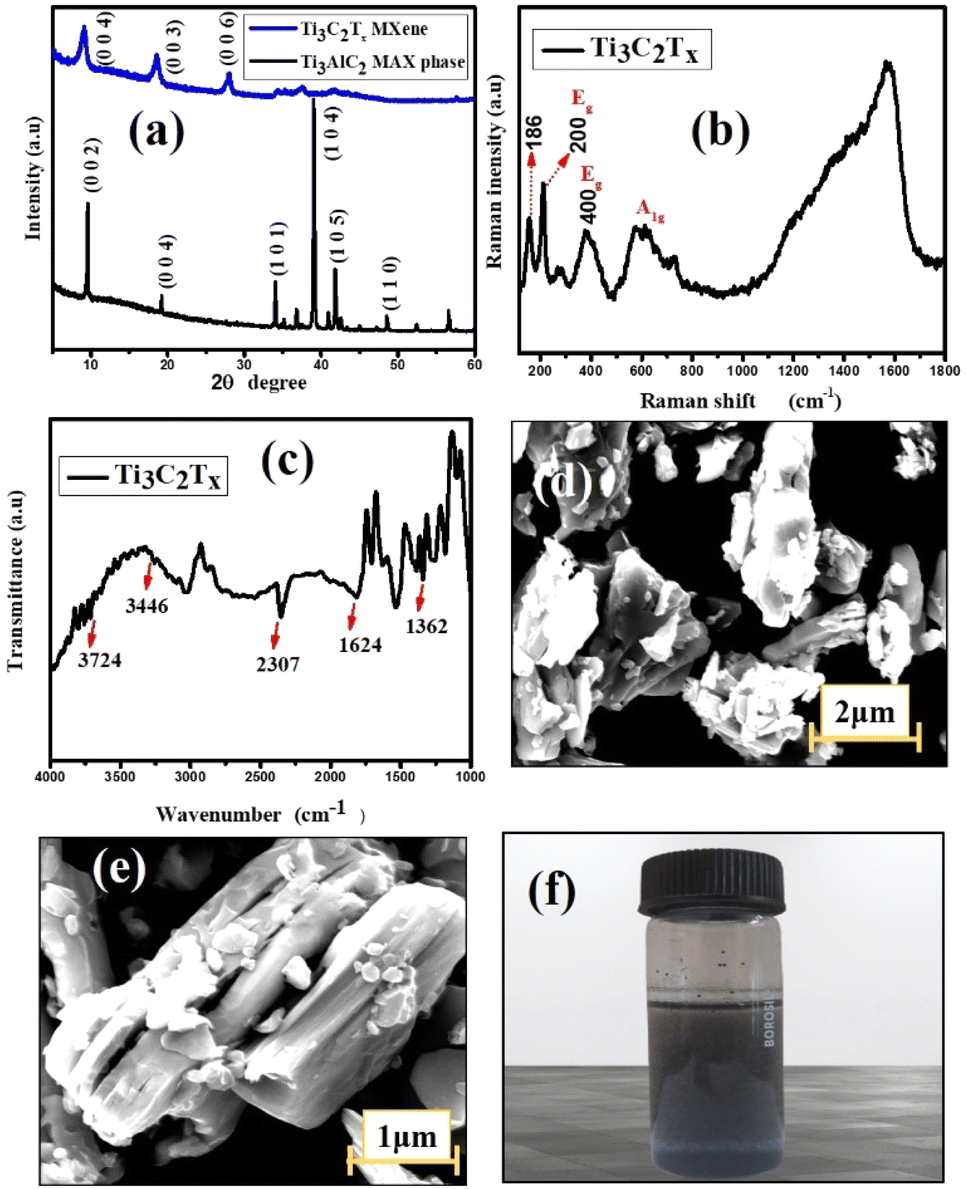
The stacked and exfoliated Ti3C2Tx structures were compared for potential structural alterations using XRD. The typical plot recorded in the 2θ (5–60°) range is displayed in Fig. 1(a). The usual properties are displayed overall in the diffraction pattern and extremely sharp peaks were seen, suggesting a high crystalline characteristic. Although the characteristic (002) peak of Ti3AlC2 has been reported to be at 2θ = 9.6°, it has been shifted to a lower value (8.7°) in this work. This is supposed to be caused by the structural expansion brought about by etching as well as the significant d-spacing that results from replacing Al with –F and –OH/–O termination groups. Another two peaks are observed at 18.3° and 27.6° with corresponding (003) and (006) planes, respectively. Additionally, in contrast to other examples in the literature,22 the intensity of the powerful peak of the MAX phase at 2θ = 38.7° is significantly smaller in Ti3C2Tx and this suggests that Al layers in Ti3AlC2 are eliminated more effectively.23
 |
| | Fig. 1 (a) XRD patterns of Ti3AlC2 & Ti3C2Tx. (b) Raman spectrum of multilayer MXene. (c) FT-IR spectrum of Ti3C2Tx. (d & e) SEM of MXene at low and high magnification respectively. (f) Ti3C2Tx solution in DMF. | |
Fig. 1(d) and (e) show SEM images of the pure multilayered MXene (Ti3C2Tx) powder. A two-dimensional property of MXene can be confirmed by looking at the magnified SEM image of the material. A frequently used method for preparing Ti3C2Tx is etching, which splits a densely packed structure into a single or multilayered substance. The multilayered MXene clearly has a flake-like structure, meaning that the exfoliation process was almost finished. The delaminated MXene showed nanoscale thickness in each layer and the characteristic layered-like structure offers clear proof that the Al atomic layer in Ti3AlC2 was successfully etched.24 The existence of an –OH peak at 3430 cm−1, 1628 cm−1, and 530 cm−1 in the FTIR spectra of m-MXene (Fig. 1(c)) further suggests the presence of an –OH group on the surface of multilayered MXene. The directional alignment of –CH2 & –CF2 dipoles for higher β-phases is facilitated by the fluorine atoms in PVDF, as they may form hydrogen bonds with the –OH on the introduced MXene and also have strong compatibility with the –F on the MXene.
According to the Raman spectra, the primary peak of MXene is represented by the peak at about 200 cm−1 while the remaining two peaks appear at ∼400 and ∼605 cm−1, showing the presence of γ- and β-phases in the hybrid composite.25,26 The peaks at around 300–800 cm−1 line up with the vibrations of the Ti–C bond (Fig. 2(b)). It is important to note that there is a tiny, distinct peak located at about 186 cm−1. This could be due of an excessively high laser power, which produced oxidized Ti3C2Tx. Ti3C2 is a member of the D3d point group unit cell. In Mulliken symbols, the vibrations of Ti3C2Tx are 4Eg + 2A1g + 4Eu + 2A2u.27 The Raman-active nodes are identified by the letters Eg and A1g, whereas the IR-active nodes, Eu and A2u, are found in an irreducible double degenerate mode. The Ti3C2Tx MXene phase was found to have four notable active Raman modes. Ti and C atoms undergo an in-plane vibrational transition known as Eg, and an out-of-plane vibration known as A1g. The two remaining modes are the in-plane and out-of-plane vibrational modes of C atoms. The solution of Ti3C2Tx MXene in DMF is represented in Fig. 1(f).
 |
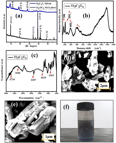
| | Fig. 2 (a) XRD patterns of the HNCs. (b) Raman analysis of the synthesized composites. (c) FT-IR plot of the composites. (d) Plot of β-phase (%) vs. wt% of GMHs present in the composite. | |
3.2 Synthesized PVDF/PMMA–xGnP/Ti3C2Tx characteristics
3.2.1. Structural analysis.
The crystalline and amorphous nature of the neat PVDF/PMMA, and its quaternary composites is shown in Fig. 2(a). The peaks at 18.7° and 20.06° are responsible for the α and β-phases of PVDF, which correspond to (1 0 2) and (0 2 3) planes respectively.28 The diffraction pattern of the polymer blend shows a few small peaks as the wt% of filler increases. The reason for this is that crystalline structures of the hybrid filler are more predominate than the semi-crystalline nature of PVDF in the blend matrix. Furthermore, the broad peak at 2θ = 18–20° denotes the amorphous nature of the PMMA structure. The high intensity peaks are basically observed in the 2θ = 25.5–27.2° and 6.2–9.7° regions. The presence of MXene and xGnP is responsible for the strong peaks in the hybrid composite. The peaks that correspond to xGnP and Ti3C2Tx are separated by the typical peaks at 26.06° and 6.60° associated with the composites respectively, suggesting that these two conducting phases were efficiently distributed in the blend composite. At high filler loading, the peak at roughly 18° vanishes because of enhanced polymer–filler interactions, which can prevent the polymer chains in PVDF/PMMA from forming a crystalline lattice and result in the production of an amorphous phase. The synthesis of MXene is confirmed by the Ti3C2Tx XRD pattern. The delamination of MXene can be verified by the peak changing from 9.3° to 7.2°.29 Thus, the two peaks at 8.7° (0 0 4) and 9.5° (0 0 2) in the synthesized MXene verify the synthesis of partially delaminated Ti3C2Tx.
The interactions between the neat PVDF/PMMA modified with varying ratios of GMHs have been demonstrated by FTIR spectroscopy, as seen in Fig. 2(c). The symmetrically elongated absorption peak of the –CF2 group and the vibration of the –CH2 group were identified as the causes of the characteristic absorption peaks for the pure blend, which were recorded at 1404 cm−1, 1234 cm−1, and 1167 cm−1. The amorphous phase of the material was responsible for the characteristic peak located at 881 cm−1, whereas the presence of the crystalline phase of PVDF was attributable to the absorption peak located at 1056 cm−1. The distinctive absorption peaks of composite and neat PVDF/PMMA were identical after the addition of GMHs, which may have been caused by the moderate change of the composite. The β-phase is associated with the absorbance bands at 512, 843, 872, and 1407 cm−1, whereas the α-phase is associated with the absorbance bands at 510, 813, and 1240 cm−1.30 The percentage of β-phase (Fβ) of the pure blend and hybrid composites can be derived using the following equation, which is provided by Gregorio & Ueno,31
| | | f(β) = Aβ/1.26 × (A∝ + Aβ) | (3) |
where
Aα and
Aβ are the corresponding absorption coefficients for the β phase (840 cm
−1) and the α phase (762 cm
−1).
Fig. 2(d) displays a graph of the percentage of the β phase
vs. wt% of GMHs in the neat blend. At first, it seemed that the percentage of β phase of the composite film was higher, but as the wt% of the hybrid filler increased, those values decreased. There might be a phase transition that changes a portion of the β phase into a new phase with distinct features which could be caused by high filler concentrations. The filler may be well-dispersed at lower concentrations, improving the % of β phase (71.04% for 10 wt% GMHs). Filler particle agglomeration may happen at larger concentrations, resulting in defects and a loss of the desired qualities.
Fig. 2(b) displays the Raman spectra of the solid GMH filled PVDF/PMMA blend and its hybrid composite. The sample contains α, β, and γ crystal phases, as shown by the spectrum of the polymer blend. There is an intense line at 815 cm−1, indicative of the α-phase, and a band at nearly 890 cm−1, typical of the γ-phase rich PVDF.32 The spectra of the pure β and γ phases show strong lines which contribute to the intensity of the peaks at 838 cm−1 and 1440 cm−1. They arise from the bending CH2 vibrations (1440 cm−1), the asymmetric stretching CF2 vibrations (line at 838 cm−1), and the rocking CH2 vibrations.33,34 The PMMA lines in the ranges of 965–1400 cm−1 are seen as a few little peaks in these regions. The Raman scattering vibration spectra of the composites indicate that the mechanically activated filler has different impacts on the crystallization of the neat blend.35 There is an increase in the α-phase content compared to the β-crystal phase when the blend was combined with the non-activated filler. The spectra of this composite are dominated by the strongest PVDF α-phase line, which is located at 815 cm−1 and the intensity of the peak increases in both 5 wt% and 10 wt% composites. The amorphous phase contributes more to the background spectrum when the composite is fabricated, particularly in the 400–570 cm−1 region. The line at 588 cm−1 and 1574 cm−1, which comes from the Ti3C2Tx, proved the presence of the hybrid filler in the overall composite. The GMHs allow PVDF to crystallize more easily in the blend because of their larger specific surfaces and lower average diameters.
3.2.2. Morphological analysis.
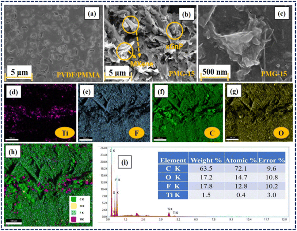
The surface morphology of the lamellar structure of the composites is depicted in Fig. 3(a–c). Although the concentration of GMHs was the greatest (20.0 wt%) in this work, the MXene and xGnP nanosheets were observed to be uniformly distributed throughout the blend matrix. Polymer chains consist of long atoms bound together by weak van der Waals interactions. This increases the flexibility, deformability, and movability of polymers and as a result voids are created within the polymer blend matrix.
 |
| | Fig. 3 FE-SEM images of (a) the PVDF/PMMA blend and (b and c) HNCs with 15 wt% GMHs. (d–h) Color mapping of the composite film. (i) EDS map scanning. | |
The dielectric constant is consequently lowered by these unoccupied regions, which also lower the charge storage capacity. In addition, the voids within the polymer cause it to lose its mechanical and physical characteristics, which makes it unstable at high temperatures.36 Polymers often include intrinsic voids or free spaces in their matrix, which can affect their dielectric performance. These gaps are efficiently filled by the introduction of 2D nanofillers, such as MXene or graphene nanoplatelets. The morphology images demonstrate that when the 10 wt% hybrid particles in the composites change along with the pore size, the size of the pores reduces as the nanoparticles begin to accumulate the voids in the PVDF/PMMA blend. This shows that adding GMHs to the blend improves the structural characteristic (density) of the composite film, which modifies the parameters of several thin film qualities.37 This is further demonstrated by XRD measurements, which show that when the weight percentage of nanoparticles rises, crystallinity of PVDF in the polymer blend continues to decline. The elements of Ti, C, F and O are uniformly distributed, according to the color maps and EDS scanning in Fig. 3(d–h) and (i), respectively, which further identifies the creation of the lamellar structured 2D GMHs.
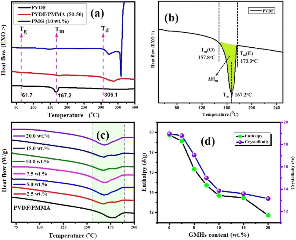
3.2.3. Thermal analysis.
The DSC melting curves for the nanocomposites are shown in Fig. 4(c). The thermogram plots show heating curves which represent the melting behavior of the prepared composites. The crystallinity (Xc) from the first heating cycle was calculated using the following formula to determine the state of the material,38| |  | (4) |
where ΔHm is the melting enthalpy of the composite sample which is calculated by integrating the area under the curve (colored shadow in Fig. 4(b)) and ΔH0100 is the melting enthalpy of 100% crystalline neat PVDF, which is 103.4 J g−1. The single melt peaks of pure PVDF and its blends are observed at around ∼167.2 °C & ∼157.7 °C respectively. The melting peak and crystallinities of the composite films are lower than those of the pure PVDF and its blend respectively. This indicates that the samples we generated primarily consist of α-form crystals. The glass transition temperature (Tg) of the neat blend is explained by a micro-Brownian motion for the main chain backbone which produces an endothermic peak at 61.7 °C.39Fig. 4(a) shows the melting (Tm) and degradation temperature (Td) for PVDF/PMMA composites which are displayed by the second and third endothermic peaks (located at 167.2 °C and 305.1 °C, respectively). The nucleating action of GMHs is demonstrated by the reduced crystallinity of the pure blend from 18.97% to 13.15% brought about by the addition of 20 wt% GMHs (Fig. 4(d)). This is because large amounts of fillers can slow down the segment mobility of PVDF chains, which can impact the kinetics of crystallization.40
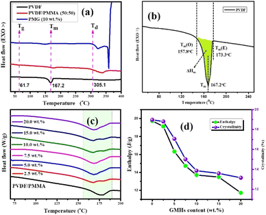 |
| | Fig. 4 DSC heating thermograms of (a) the 10 wt% GMH composite. (b) Onset melting temperature Tm(o), peak melting temperature (Tm), end set temperature Tm(E), change in melting temperature (ΔTm), and melting enthalpy (ΔHm) of pure PVDF, (c) DSC melting curves of the PVDF/PMMA-GMH composites and (d) melting enthalpy & crystallinity. | |
Thus, these findings suggest that both Ti3C2Tx and xGnPs function as nucleating agents for PVDF crystallization more successfully. It may be suggested that the zigzag carbon atoms at the surface of xGnP can match the PVDF segments with all-trans conformation, improving the crystallization, but the presence of PMMA can reduce the overall crystallinity due to its dominating amorphous nature in the composites. All the crystalline parameters of HNCs are displayed in Table 1.
Table 1 Crystallinity of HNCs determined by DSC analysis
| Sample |
T
m(O) (°C) |
T
m (°C) |
T
m(E) (°C) |
ΔTm (°C) |
ΔHm (J g−1) |
X
c (%) |
| PVDF |
157.8 |
167.2 |
173.3 |
15.5 |
42.76 |
41.11 |
| PVDF/PMMA |
145.0 |
176.7 |
189.2 |
44.2 |
19.73 |
18.97 |
| 2.5 wt% |
147.9 |
168.1 |
187.2 |
39.3 |
19.11 |
18.80 |
| 5.0 wt% |
148.4 |
169.0 |
186.5 |
38.1 |
16.31 |
17.06 |
| 7.5 wt% |
149.5 |
169.2 |
186.1 |
36.6 |
14.72 |
15.0 |
| 10.0 wt% |
150.2 |
169.7 |
185.7 |
35.5 |
13.70 |
13.86 |
| 15.0 wt% |
150.8 |
170.2 |
186.7 |
35.9 |
13.48 |
13.59 |
| 20.0 wt% |
149.7 |
168.9 |
185.4 |
35.7 |
11.72 |
13.15 |
3.2.4. Dielectric analysis.
The dielectric constant and loss spectra of the pristine PVDF/PMMA blend and nanocomposites with GMHs are illustrated in Fig. 5(a and b). As frequency increases, the dielectric constant and loss both decrease. The dielectric spectra of HNCs exhibit greater dielectric constant than those of MXene NCs, particularly for the 15 wt% films. The dielectric parameter has been calculated using the well-known formula,| | | ε′ = (l × Cp)/(A × ε0) | (5) |
where Cp is the parallel capacitance (obtained experimentally), εo is permittivity of free space (εo = 8.854 × 10⁻¹² F m−1), A is the area of the film and l is the thickness of the composite film respectively. The dielectric loss (ε′′) of the sample is calculated using the following relation,where D is the loss tangent or dissipation factor (tanδ) spectrum derived for polymer blend composites. The dielectric loss increases and decreases with frequency at room temperature but rises with increasing temperature. The various relaxation mechanisms present in the materials are the cause of the dielectric constant and loss fluctuation with frequency. There may be α-relaxation in the crystalline area, which primarily takes place at roughly 1 MHz and accounts for the significant loss and dielectric constant at low frequencies.41 The orientation polarization of the blend matrix and interface polarization loss are the primary sources of dielectric loss at low frequencies, while the increased mobility of polymer chains within the PVDF matrix causes dielectric relaxation at high frequencies.42
 |
| | Fig. 5 Frequency dependence of (a) real permittivity, (b) tanδ and (c) ac conductivity, (d) temperature dependent ε′ and tanδ at different frequencies for 15 wt% HNCs, (e) plot of ln(σac) vs. 1000/T at different frequencies, (f) ε′ and tanδ with different wt% of GMH loading, (g and h) comparisons (ε′ and tanδ) of the PVDF/PMMA with 15 wt% MXene and 15 wt% GMH loading respectively. | |
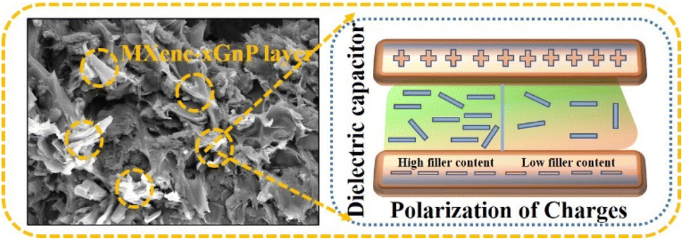
However, the increased slope of the dielectric spectra in the HNCs indicates that the MWS (Maxwell–Wagner–Sillars) polarization mechanism has shifted to higher frequencies. At the same time, a higher filler concentration (15 wt%) may result in the creation of more micro-capacitive structures in the composite films, which would raise the dielectric constant. Furthermore, the FTIR results indicate that as the filler concentration increases, so does the β phase content in the PVDF matrix. Moreover, an increase in the polar β phase can raise the dielectric constant of films.43 The temperature dependent ε′ and tanδ at different frequencies for 15 wt% HNCs are displayed in Fig. 5(d). Despite this, when the GMH content is raised to 20 wt%, the dielectric constant cannot be further improved because the dispersion inside the PVDF/PMMA blend matrix deteriorates and the interfacial effect becomes weaker as shown in Fig. 5(f). Different polarization mechanisms (such as dipolar, ionic, or electronic polarization) may become more active at higher temperatures. In particular, dipolar polarization tends to develop as thermal energy makes it easier for the dipoles inside the polymer chains to orient themselves in response to an external electric field. As a result, the 20 wt% composite has a lower dielectric constant than the 10 & 15 wt% composites. The HNC composite with 15 wt% GMH loading generally has a high dielectric constant of 157.4 and a dielectric loss of 0.091 at 100 Hz as shown in Fig. 5(a). The PVDF/PMMA-15 wt% MXene and PVDF/PMMA-15 wt% GMHs are compared in terms of ε′ and tanδ in Fig. 5(g and h). The phenomenon of increased permittivity in polymer composites containing a conductive filler is explained by the formation of a network of micro-capacitors. The composites have fewer micro-capacitor structures at low filler concentrations because of the wide spacing between xGnP–MXene nanosheets. As Fig. 6 illustrates, the number of microcapacitor structures increases quickly as the gap between MXene nanosheets decreases with an increase in filler content.44,45 The conductive nanocomposites with a high dielectric constant may be able to store a significant quantity of charge due to the broad network composed of many capacitors. The findings show that the composite material satisfies the requirements for practical applications with its reasonable filling amount, easy fabrication process, and good dielectric qualities.
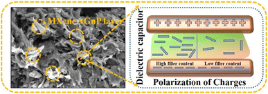 |
| | Fig. 6 Diagrammatic representation of polarization processes associated with the conductive composite. | |
3.2.5. Conductivity analysis.
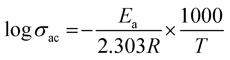
The alternative current conductivities (σac) of all films were determined as a function of frequency at 25 °C, as indicated in Fig. 5(c). The conductivity of every layer increased in a nearly linear pattern as the frequency was raised which demonstrates their strong insulating nature. As a result, they might be employed in the dimensional design of high-performance, low-frequency operating electrical devices or components as flexible-type electrical insulators. As predicted, the highly conductive characteristic of the MXene would cause a rise in the ac conductivity of all homogeneous films when its concentration increased.46 The values of the various compositions of these HNC films increase, with some non-linearity, from 10−9 S cm−1 to 10−2 S cm−1 when the frequency of the applied electric field is increased from 100 Hz to 5 MHz. These polymer blend composites exhibit conductivity dispersion behavior that is comparable to that of a number of other polymer nanocomposite materials.47,48 As expected, the advantageous low ac conductivity of 15 wt% (8.04 × 10⁻⁸ S cm−1) was verified, demonstrating a significant contribution from the barrier effect to the ac conductivity reduction. Naturally, the conductivity would drop if the interface barrier effect prevented electric tree growth throughout the GMH layer in the surface of the composite. At lower frequencies, long-to-short-distance charge movement dominates the electrical conduction in these host polymer matrices. However, as the literature discusses, localized charge movement controls the electrical conduction in the materials over higher frequency fields.49 The Arrhenius formula is followed by the linear connection between logσ and 1000/T,50| | 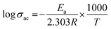 | (7) |
where T is the absolute temperature, R is the molar gas constant (8.314 J mol−1 K−1), and Ea is activation energy. The decreasing linear relationship between logσ and 1000/T is maintained in Fig. 5(e), indicating that rising temperatures can lead to a drop in σac, a phenomenon particularly apparent in semiconductors. At high temperature, the polymer molecules will have high energy, which makes it easier for their bonds to break. Thus, increasing the amorphous area may speed up the movement of ions. Additionally, the results show that ions migrate more easily in the composite with reduced crystallinity.
3.2.6. Impedance analysis.
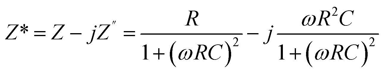
The application of complex impedance spectroscopy (CIS) technology might provide insight into the origins of the dielectric relaxation mechanism related to the dynamics of bound or mobile charges in the bulk or interfacial regions of the examined materials. Fig. 7(a–c) display the real (Z′) and imaginary (Z′′) parts of the impedance plot for HNCs that were tested at 25 °C. The complex impedance and modulus are examined by using the formula,| | 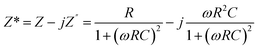 | (8) |
where the complex impedance (Z*) is denoted by the real (Z′) and imaginary (Z′′) components, the complex modulus (M*) is represented by the real (M′) and imaginary parts (M′′) of the electric modulus, ε′ & ε′′ are real and imaginary permittivity, ω is applied frequency, R = resistance and C = capacitance respectively. It is evident from the observations that both the values are greater at lower frequencies, drop monotonically with increasing frequency and reach a constant value with higher frequencies. This phenomenon may be explained by the general tendency of polymeric materials to polarize, which happens when they locally displace in the direction of the applied field in response to the ionic exchange of the number of ions. This behavior results from the absence of charge accumulation at the interface and the decreasing polarization as the space charges lose their ability to sustain and react to the external field. Complex impedance is high at low frequencies, which may be due to space charge polarization. The Nyquist plots (Z′ vs. Z′′) for the nanocomposite at room temperature are displayed in Fig. 7(c). The contributions of grains (g) and grain boundaries (gb) to the resistive properties of the materials are distinguished by the impedance spectrum, which consists of one or more semicircles. A parallel CQR (Q = constant phase element) circuit might serve as an analogous circuit that represents the electrical characteristics of the sample as shown in Fig. 7(d).
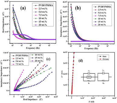 |
| | Fig. 7 (a) Frequency vs. real impedance (Z′), (b) frequency vs. imaginary impedance (Z′′). (c) Nyquist plot (Z′ vs. Z′′) for composites at 25 °C. (d) Fitting parameter and the equivalent circuit diagram for composites. | |
3.2.7. Ferroelectric analysis.
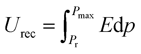
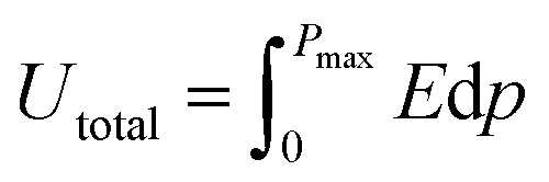
The ferroelectric hysteresis loop for PVDF/PMMA and the PVDF/PMMA-GMHs composite when exposed to an electric field is shown in Fig. 8(a). The hysteresis loops that have been found suggest that the ferroelectric characteristics of the nanocomposite film remain favorable. The equal distribution of the hybrid filler inside the blend matrix is probably responsible for the decrease in saturation polarization value that occurs with an increase in filler content. It contains the energy storage capacity of the material. The maximum polarization (Pmax), remnant polarization (Pr), and external electric field (E) control the energy density of the composite as indicated by the formulae below,51| |  | (9) |
| |  | (10) |
where recovered energy density (Urec) and total energy storage (Utotal) are the relevant terms. The energy storage density inside the P–E loop determines the energy storage efficiency (η), which is determined by,| |  | (11) |
In contrast, the lost energy density is denoted by W2 and the restored energy density by W1. The overall energy density included in the composites is represented by the sum of the values for W1 and W2. The W2 in this case corresponds to the right loop, whereas the W1 is linked to the left loop as shown in Fig. 8(b). The composite that contains 15 wt% GMHs has the largest polarization, which is probably caused by the maximum β phase being present as depicted in Fig. 8(c). The interaction between hybrid nanofillers and the PVDF/PMMA blend matrix at the interface causes the increased polarization. The highest energy density obtained for the 15 wt% composite is 2.78 J cm−3, while the pure blend has an energy density of 1.05 J cm−3 that may be the cause of the increase in polarization (Fig. 8(d)). Overall, a substantial increase in maximum polarization and energy storage efficiency was achieved at a relatively high filler content, ensuring the integrity of the composites and maintaining a high degree of energy storage capacity.
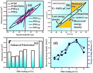 |
| | Fig. 8
P–E hysteresis loop of (a) the composite film and (b) PVDF/PMMA blend. (c) Remnant polarization (Pr) and (d) recovered energy density (W1) and storage efficiency (η) with different wt% GMHs at ambient temperature. | |
4. Application
The breakdown strength and the dielectric constant are the two main factors that affect the energy density of the dielectric capacitor. Polymer chains consist of long atoms bound together by weak van der Waals interactions. Because of this, polymers are more flexible and easily adaptable and moveable, causing the polymer to develop a void inside. These empty regions lower the dielectric constant by decreasing the capacity to store charges. To refill the empty voids inside the polymer and improve the stability and charge occupancy of the polymer matrix, 2D hybrid fillers like MXene and xGnP improve the dielectric characteristics of these materials.52 The recovered energy density (Urec) of the polymer nanocomposite is increased when 2D nanofillers are present because they prevent charges from moving freely in the direction of an applied electric field.
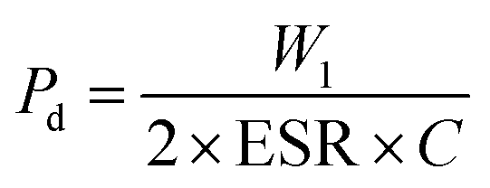
It is important that the energy storage performance of the PVDF/PMMA blend can be significantly increased without the need for surface functionalization by only incorporating a high loading of GMHs (about 15 wt%). In addition to energy storage density, power density is another important factor to consider when assessing the effectiveness of energy storage systems. Furthermore, the power density is evaluated by using the energy storage density. Ragone theory can be utilized for calculating it as,53
| | 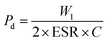 | (12) |
| |  | (13) |
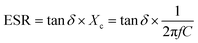
In this case, capacitive reactance (
Xc) and dielectric loss (tan
δ) are used to calculate the equivalent series resistance (ESR). After putting the value of ESR in
eqn (12), we will obtain the overall power density value,
54,55| |  | (14) |
At room temperature, the material has a maximum power density of 12.12 MW cm−3 at 1 kHz. Table 2 summarizes the energy-storage efficiency (η), power density (Pd), and recovered energy density (W1) of the HNCs. The 15 wt% HNC shows better storage efficiency (η) = 69.7% and Pdmax = 12.12 MW cm−3 under a 5 kV cm−1 electric field which has potential for energy-storage capacitor applications which is also confirmed by dielectric and conductivity parameters. The use of GMH composites can significantly improve the overall performance of capacitors due to their outstanding energy storage capabilities. Consequently, the HNCs are typically employed as a separator for batteries and capacitors.
Table 2 Different parameters calculated from the P–E hysteresis loop at room temperature
| Sample name |
Recovered energy density (W1) (J cm−3) |
Remnant polarization (Pr) (μC m−2) |
Power density (Pd) (MW cm−3) |
Energy storage efficiency (η) (%) |
| PMG0 |
1.05 |
0.031 |
9.42 |
60.6 |
| PMG2.5 |
1.29 |
0.022 |
7.10 |
60.4 |
| PMG5.0 |
1.31 |
0.023 |
8.06 |
64.5 |
| PMG7.5 |
1.52 |
0.033 |
9.00 |
65.5 |
| PMG10 |
2.32 |
0.036 |
10.71 |
68.8 |
| PMG15 |
2.78 |
0.034 |
12.12 |
69.7 |
| PMG20 |
1.58 |
0.053 |
6.70 |
66.6 |
5. Summary and conclusion
A flexible and adaptable PVDF/PMMA hybrid composite with 2D xGnP–MXene fillers has been processed through the solution casting method. XRD and FT-IR validate the existence of 2D xGnP–MXene and a β-phase in the characteristic investigations. The homogeneous distribution of GMHs in the PVDF/PMMA matrix and an increase in structural density are seen in the surface morphological images captured by FE-SEM. It is evident that the interfacial polarization between the polymer matrix and GMHs is what causes the notable rise in the dielectric constant and loss. The conductivity and dissipation factor indicate that the polarity of the nanocomposites is improved by an increase in charge carrier mobility and an increase in conductivity as the concentration of filler increases. The ferroelectric characteristics of the material are evaluated through the analysis of the hysteresis loop. The results indicate that HNC films can develop into high-performance energy storage capacitors, with a high efficiency of 69.7% (η) and a maximum power density (Pdmax) of 12.12 MW cm−3. These NCs are also a promising material for the upcoming generation of automated energy storage devices. It can be challenging to achieve homogeneous dispersion of MXene and xGnP in the PVDF matrix at higher scales. The characteristics of the composite may be compromised by filler aggregation. MXenes are oxidizable, particularly when being processed or stored. This can make large-scale preparation more difficult and cause their qualities to deteriorate. The multi-step chemical etching of MXene can be costly and time-consuming. It is still difficult to scale up without sacrificing effectiveness or increasing expenses.
Data availability
The data used for the preparation of the manuscript are available from the corresponding author.
Author contributions
The manuscript was written through contributions of all authors. All authors have given approval to the final version of the manuscript.
Conflicts of interest
There are no conflicts of interest to declare.
References
- X. Zhao, S. Chen, J. Zhang, W. Zhang and X. Wang, J. Cryst. Growth, 2011, 328, 74–80 CrossRef CAS.
- S. Aid, A. Eddhahak, S. Khelladi, Z. Ortega, S. Chaabani and A. Tcharkhtchi, Polym. Test., 2019, 73, 222–231 CrossRef CAS.
- P. M. Martins, S. Ribeiro, C. Ribeiro, V. Sencadas, A. C. Gomes, F. M. Gama and S. Lanceros-Méndez, RSC Adv., 2013, 3, 17938 RSC.
- D. Mondal, A. L. Gayen, B. K. Paul, P. Bandyopadhyay, D. Bera, D. S. Bhar, K. Das, P. Nandy and S. Das, J. Mater. Sci.: Mater. Electron., 2018, 29, 14535–14545 CrossRef CAS.
- G. H. Kim, S. M. Hong and Y. Seo, Phys. Chem. Chem. Phys., 2009, 11, 10506 RSC.
- T. Roopa, H. N. Murthy, D. Harish, A. Jain and G. Angadi, Polym. Polym. Compos., 2020, 29, 198–206 Search PubMed.
- M. Fortunato, C. Chandraiahgari, G. De Bellis, P. Ballirano, F. Sarto, A. Tamburrano and M. Sarto, Nanomaterials, 2018, 8, 743 CrossRef PubMed.
- T. A. Ezquerra, J. C. Canalda, A. Sanz and A. Linares, Colloid Polym. Sci., 2014, 292, 1989–1998 CrossRef CAS.
- B. T. S. Ramanujam, P. V. Adhyapak, S. Radhakrishnan and R. Marimuthu, Polym. Bull., 2020, 78, 1735–1751 CrossRef.
-
B. T. S. Ramanujam and S. Radhakrishnan, in Trends and Applications in Advanced Polymeric Materials, Scrivener Publishers, USA, 2017, pp. 127–143 Search PubMed.
- J.-H. Yang, Y.-S. Zhang, F. Xue, D.-F. Liu, N. Zhang, T. Huang and Y. Wang, Polymer, 2021, 229, 123998 CrossRef CAS.
- F.-C. Chiu and Y.-J. Chen, Composites, Part A, 2014, 68, 62–71 CrossRef.
- W. Li, Z. Song, J. Zhong, J. Qian, Z. Tan, X. Wu, H. Chu, W. Nie and X. Ran, J. Mater. Chem. C, 2019, 7, 10371–10378 RSC.
- K. R. G. Lim, M. Shekhirev, B. C. Wyatt, B. Anasori, Y. Gogotsi and Z. W. Seh, Nat. Synth., 2022, 1, 601–614 CrossRef CAS.
- W. Wu, W. Zhao, Q. Sun, B. Yu, X. Yin, X. Cao, Y. Feng, R. K. Y. Li and J. Qu, Compos. Commun., 2021, 23, 100562 CrossRef.
- W. Li, Z. Song, J. Zhong, J. Qian, Z. Tan, X. Wu, H. Chu, W. Nie and X. Ran, J. Mater. Chem. C, 2019, 7, 10371–10378 RSC.
- A. Tsyganov, M. Vikulova, D. Artyukhov, D. Zheleznov, A. Gorokhovsky and N. Gorshkov, Nanomaterials, 2023, 13, 1337 CrossRef CAS PubMed.
- A. Rajeh, H. A. Althobaiti, S. J. Almehmadi, H. A. Alsalmah, N. A. Masmali, A. I. Al-Sulami and M. Al-Ejji, J. Inorg. Organomet. Polym. Mater., 2023, 34, 1221–1231 CrossRef.
- Y. Feng, J.-L. Li, W.-L. Li, M.-L. Li, Q.-G. Chi, T.-D. Zhang and W.-D. Fei, Composites, Part A, 2019, 125, 105524 CrossRef CAS.
- L. Jing, W. Li, C. Gao, M. Li and W. Fei, Compos. Sci. Technol., 2022, 227, 109568 CrossRef CAS.
- R. J. Sengwa and N. Kumar, Chem. Phys. Impact, 2023, 7, 100281 CrossRef.
- C. Zhao, Q. Wang, H. Zhang, S. Passerini and X. Qian, ACS Appl. Mater. Interfaces, 2016, 8, 15661–15667 CrossRef CAS PubMed.
- Y. Cao, Q. Deng, Z. Liu, D. Shen, T. Wang, Q. Huang, S. Du, N. Jiang, C.-T. Lin and J. Yu, RSC Adv., 2017, 7, 20494–20501 RSC.
- T. Zhang, L. Pan, H. Tang, F. Du, Y. Guo, T. Qiu and J. Yang, J. Alloys Compd., 2017, 695, 818–826 CrossRef CAS.
- A. Sarycheva and Y. Gogotsi, Chem. Mater., 2020, 32, 3480–3488 CrossRef CAS.
- M. Pramanik, M. V. Limaye, P. K. Sharma, M. Mishra, S. K. Tripathy and S. B. Singh, ACS Appl. Mater. Interfaces, 2024, 16, 29121–29131, DOI:10.1002/app.43605.
- S. S. Ray, T. S. K. Sharma, S. Myung, W. M. Choi and Y.-N. Kwon, Desalination, 2024, 580, 117536 CrossRef CAS.
- W. Wu, W. Zhao, Q. Sun, B. Yu, X. Yin, X. Cao, Y. Feng, R. K. Y. Li and J. Qu, Compos. Commun., 2020, 23, 100562 CrossRef.
- A. Qian, S. E. Hyeon, J. Y. Seo and C.-H. Chung, Electrochim. Acta, 2018, 266, 86–93 CrossRef CAS.
- K. Deshmukh, M. B. Ahamed, S. Sankaran, S. K. K. Pasha, K. K. Sadasivuni, D. Ponnamma and M. A.-A. AlMaadeed, Mater. Today Proc., 2018, 5, 8744–8752 CrossRef CAS.
- R. Gregorio Jr and E. M. Ueno, J. Mater. Sci., 1999, 34, 4489–4500 CrossRef.
- T. Boccaccio, A. Bottino, G. Capannelli and P. Piaggio, J. Membr. Sci., 2002, 210, 315–329 CrossRef CAS.
- S. Satapathy, S. Pawar, P. K. Gupta and K. B. R. Varma, Bull. Mater. Sci., 2011, 34, 727–733 CrossRef CAS.
- M. Kobayashi, K. Tashiro and H. Tadokoro, Macromolecules, 1975, 8, 158–171 CrossRef CAS.
- X. Zhou and M. Cakmak, J. Macromol. Sci., Part B: Phys., 2007, 46, 667–682 CrossRef CAS.
- Q. Jia, X. Huang, G. Wang, J. Diao and P. Jiang, J. Phys. Chem. C, 2016, 120, 10206–10214 CrossRef CAS.
- C.-T. Pan, K. Dutt, A. Kumar, R. Kumar, C.-H. Chuang, Y.-T. Lo, Z.-H. Wen, C.-S. Wang and S.-W. Kuo, Int. J. Bioprint., 2022, 9, 647 CrossRef PubMed.
- K. Ke, R. Wen, Y. Wang, W. Yang, B.-H. Xie and M.-B. Yang, J. Mater. Sci., 2010, 46, 1542–1550 CrossRef.
- E. M. Abdelrazek, A. M. Abdelghany, S. I. Badr and M. A. Morsi, J. Res. Updates Polym. Sci., 2017, 6, 45–54 CrossRef CAS.
- N. K. Nath, R. R. Mohanta, R. K. Parida, B. N. Parida and N. C. Nayak, J. Appl. Polym. Sci., 2024, 141(31), e55729 CrossRef CAS.
- C. V. Chanmal and J. P. Jog, eXPRESS Polym. Lett., 2008, 2, 294–301 CrossRef CAS.
- L. Lv, L. Huang, P. Zhu, G. Li, T. Zhao, J. Long, R. Sun and C. Wong, J. Mater. Sci.: Mater. Electron., 2017, 28, 13521–13531 CrossRef CAS.
- S. Mishra, R. Sahoo, L. Unnikrishnan, A. Ramadoss, S. Mohanty and S. K. Nayak, Mater. Res. Bull., 2019, 124, 110732 CrossRef.
- N. K. Nath, R. R. Mohanta, R. K. Parida, B. N. Parida and N. C. Nayak, Mater. Today Chem., 2024, 41, 102338 CrossRef CAS.
- S. Luo, S. Yu, R. Sun and C.-P. Wong, ACS Appl. Mater. Interfaces, 2013, 6, 176–182 CrossRef PubMed.
- X. Liang, A. Garsuch and L. F. Nazar, Angew. Chem., 2015, 127, 3979–3983 CrossRef.
- R. J. Sengwa, N. Kumar and M. Saraswat, Mater. Today Commun., 2023, 35, 105625 CrossRef CAS.
- R. Ram, M. Rahaman and D. Khastgir, Composites, Part A, 2014, 69, 30–39 CrossRef.
- S. X. Drakopoulos, A. C. Patsidis and G. C. Psarras, Mater. Res. Bull., 2022, 145, 111537 CrossRef CAS.
- S. Karan, M. Sahu, T. B. Sahu, Y. K. Mahipal, D. K. Sahu and R. C. Agrawal, Mater. Today Commun., 2017, 13, 269–274 CrossRef CAS.
- B. Chu, X. Zhou, K. Ren, B. Neese, M. Lin, Q. Wang, F. Bauer and Q. M. Zhang, Science, 2006, 313, 334–336 CrossRef CAS PubMed.
- S. J. Kim, M. Jang, G. Jeong, S. Yu, J. Park, Y. Lee, S. Cho, J. Yeom, Y. Lee, A. Choe, Y.-R. Kim, Y. Yoon, S. S. Lee, K.-S. An and H. Ko, Nano Energy, 2021, 89, 106409 CrossRef.
- T. Christen and M. W. Carlen, J. Power Sources, 2000, 91, 210–216 CrossRef CAS.
- M. P. Manoharan, C. Zou, E. Furman, N. Zhang, D. I. Kushner, S. Zhang, T. Murata and M. T. Lanagan, Energy Technol., 2013, 1, 313–318 CrossRef CAS.
- S. S. Hota, D. Panda and R. N. P. Choudhary, J. Power Sources, 2024, 599, 234223 CrossRef CAS.
|
| This journal is © The Royal Society of Chemistry 2025 |
Click here to see how this site uses Cookies. View our privacy policy here. 
 Open Access Article
 This Open Access Article is licensed under a Creative Commons Attribution-Non Commercial 3.0 Unported Licence
 *a
*a