DOI:
10.1039/D4SM01218F
(Paper)
Soft Matter, 2025,
21, 5398-5412
Immobilization and interfacial activation of lipase at liquid and solid interfaces†
Received
16th October 2024
, Accepted 3rd March 2025
First published on 10th March 2025
Abstract
This study investigates the adsorption behaviour of Candida rugosa lipase at silica/water and oil/water interfaces by means of molecular dynamics simulations. The findings reveal distinct adsorption orientations and structural differences that can be related to different enzymatic activities and selectivities. At the silica/water interface, lipase adsorbs with the LID region facing the solvent, in a configuration that is not fully open, but still grants access to its catalytic triad, as shown by tunnel calculations. These also reveal the presence of two ester-exit tunnels, suggesting a high catalytic turnover capability of the adsorbed enzyme. Docking simulations predict binding of triacylglyceride substrates with marked selectivity regarding the length of the hydrophobic chains and the substrate chirality. At the oil/water interface, lipase adsorbs via the LID region with widely open ingress tunnels, facilitating direct substrate extraction from the interface. The two opposite adsorption orientations allow favorable interactions of silica-immobilized lipase with oil droplets that cause no appreciable change in the conformation, activity, or selectivity. These results provide a molecular-scale rationalization of the lipid hydrolysis mechanisms that support the deployment of lipase immobilized in ceramic membranes for lipolytic applications.
1 Introduction
The adsorption of proteins at interfaces and the functionalization of surfaces with enzymes are of great significance. They find application in natural digestion processes and industrial processes, where, for example, lipases are immobilized on support structures.1–4 Especially the immobilization of Candida rugosa lipase is of great interest, as the enzyme experiences an increase in lipolytic activity after adsorption onto hydrophobic surfaces.5,6 The activation of the enzyme is necessary for the hydrolysis of triacylglycerides into fatty acids and glycerol. A major advantage of lipase in industrial and scientific applications is the fact that the structure has been extensively studied in the literature. Therefore, structural details, information about its stability under different conditions and, most importantly, its activity under varying reaction conditions like pH,7 enzyme preparations,8,9 presence of water10–12 and type of solvent13,14 are known. Adlercreutz et al.15 emphasize the positive effect of water on lipase-catalyzed reactions, due to the increased internal flexibility of the enzyme as well as the increased polarity of the active site.
Rehm et al.14 used molecular dynamic simulations to analyze the opening of the LID domain in lipases. They found a solvent-induced LID opening of three different lipases in toluol, whereas no LID opening of the initially closed structure in water could be observed. This underlines the complexity of the interfacial activation of lipase and highlights the interplay of solvent, surface, and enzyme. The activation of the enzyme is usually referred to as the opening of a helical LID structure (consisting of TYR69, PRO74, ALA76, GLU88), which blocks the catalytic site of the protein (SER209, GLU341, HIS449) in the inactive state, making it inaccessible to substrates.6,16–19 Several experimental studies found an improvement in activity and stability due to the immobilization of different lipases on silica20,21 and other supports.22,23 This is of particular interest for the biochemical and pharmaceutic industries, as the handling of immobilized proteins is easier, safer, and can lead to larger conversion yields. Furthermore, substrate selectivity and enantiomeric selectivity were found to be enhanced after immobilization.3,23–27 This is often ascribed to conformational changes in the molecule15,28 that lead to a stabilization of the open (active) conformation, due to hydrophobic interactions.22 Mutation studies strongly suggest that lipase LID structure plays an important role in modulating activity, specificity, and enantioselectivity.29 Furthermore, the hydrophobic nature of the open LID conformation indicates a high affinity towards hydrophobic substrates.19 However, the exact mechanisms behind the adsorption dependent activity and selectivity remain unclear. A molecular-level understanding of the governing mechanisms would enable the engineering of immobilized enzymes with selectivity that matched the exact hydrolytic requirements. It is therefore important to gain insight into the adsorption configurations, binding residues, and conformational changes of the LID structure and the catalytic triad of lipase after adsorption to both hydrophilic and hydrophobic interfaces. In this work, we perform molecular dynamics (MD) simulations of lipase at water–silica interfaces, water–oil interfaces and a combination of both interfaces to gain a detailed insight into the interfacial adsorption behaviour. In particular, we address the influence of bulk water on the enzyme activity by studying the accessibility of the catalytic site under different solvent conditions. Docking simulation of hydrophobic substrates at the catalytic triad give insight into putative binding motifs and enzyme selectivity.
2 Methods
2.1 Protein and interface models
The LIP1 enzyme of the lipase family has been chosen for our study, because it is known to have the highest activity for the hydrolysis of most assayed triacylglycerides.30 Complete high-resolution structures with distinguished open and closed states are available in the Protein Data Bank. The open and closed conformations of Candida rugosa lipase1 have the codes 1CRL31 and 1TRH,32 respectively. The globular protein consists of 534 amino acids with a calculated radius of gyration of 2.24 nm in GROMACS.33 The carbohydrate moiety attached to ASN351 to experimentally stabilize the open LID in the 1CRL structure was removed from the structure prior to simulations. The protonation state of the titradable amino acids were adjusted to a pH of 7.1 using the H++ web server version 3.2.34 All known disulfide bonds were assigned manually. Both structures were solvated in TIP3P water and 17 Na+ ions were added to ensure the charge neutrality of the system using the GROMACS package.33 The systems were energy minimized to a maximum force of 1000.0 kJ mol−1 nm−1 and equilibrated to 1 bar and 300 K for 10 ns with the AMBER-99SB force field using consecutive runs within the NVT, NPT, and NVE ensembles under periodic boundary conditions. The systems with the proteins 1CRL (A0 in Table 1) and 1TRH (E0 in Table 1) in ionic aqueous solution are studied as reference systems for the analysis of immobilized proteins. The equilibrated protein structure in solution is used as the initial structure for the surface simulations (systems AI-D and EI to H in Table 1).
Table 1 Overview of the simulated systems
| Name |
System |
No. of ion |
No. of water |
Cell dimension (nm3) |
Simulation time (ns) |
| A0 |
1CRL bulk |
17 Na+ |
22![[thin space (1/6-em)]](https://www.rsc.org/images/entities/char_2009.gif) 118 118 |
10 × 10 × 10 |
500 |
| AI |
1CRL and SiO2 |
146 Na+ |
74092 |
12 × 12 × 18 |
1000 |
| AII |
1CRL and SiO2, (AI-Δxy) |
146 Na+ |
74092 |
12 × 12 × 18 |
1000 |
| AIII |
1CRL and SiO2, (AI-Δxy) |
146 Na+ |
74092 |
12 × 12 × 18 |
1000 |
| B |
1CRL and SiO2, (AI-Δϕ) |
146 Na+ |
71803 |
12 × 12 × 18 |
580 |
| C |
1CRL and SiO2, (AI-Δϕ) |
146 Na+ |
78701 |
12 × 12 × 18 |
612 |
| D |
1CRL and SiO2, (AI-Δϕ) |
146 Na+ |
78534 |
12 × 12 × 18 |
600 |
| E0 |
1TRH bulk |
17 Na+ |
22101 |
10 × 10 × 10 |
500 |
| EI |
1TRH and SiO2 |
146 Na+ |
78708 |
12 × 12 × 18 |
1000 |
| EII |
1TRH and SiO2, (EI-Δxy) |
146 Na+ |
78708 |
12 × 12 × 18 |
1000 |
| EIII |
1TRH and SiO2, (EI-Δxy) |
146 Na+ |
78708 |
12 × 12 × 18 |
1000 |
| FI |
1CRL and MCT |
19 Na+ |
48485 |
11 × 11 × 22 |
1000 |
| FII |
1CRL and MCT |
19 Na+ |
48485 |
11 × 11 × 22 |
1000 |
| FIII |
1CRL and MCT |
19 Na+ |
48485 |
11 × 11 × 22 |
1000 |
| G |
1CRL, SiO2 and MCT |
150 Na+ |
97345 |
12 × 12 × 25 |
1000 |
| H |
1TRH and MCT |
19 Na+ |
48483 |
11 × 11 × 22 |
400 |
The oil interface was modeled using medium-chained triacylglycerides (MCT) containing 8 C atoms (C8–C8–C8) based on the work of Schestkowa et al.35 The model system consists of 850 triacylglyceride molecules which results in an interface slab of 11 × 11 × 7 nm3, equilibrated to a density of 945 kg m−3. For the silica substrate, we have used an amorphous silica slab model developed by Cole et al.36 In our previous work by Buthenuth et al.37 we have included interaction potentials for titratable surface groups of the silica–water interface to adjust the surface to physiological pH conditions. The interaction potential is capable of adequately describing the interactions of both polar and nonpolar groups of amino acid side chains with silica.37 In previous works by Hildebrand et al.38,39 we have successfully applied the surface model and the potential to study the adsorption of enzymes to silica. We could show that proteins with a distinct dipole moment resulting from a non-uniform charge distributions adsorb in significantly different orientations depending on the pH value on our silica surface model. Furthermore, the dynamic behavior of the adsorbed protein is strongly influenced by the local distribution of charged surface groups. The local conformational changes induced by the surface were analyzed by comparing the experimental and calculated CD spectra of the adsorbed protein conformations.40 In this work, a multiply repeated slab model with lateral dimensions of 12.38941 × 12.38941 nm2 in the xy plane has been chosen to allow for the simulation of single adsorbed proteins with a diameter of about 5.5 nm and to avoid spurious interactions with periodically repeated protein images. In the z direction the slab forms the interface to the solvated protein environment with a total cell height of 18.04524 nm. The protonation states of the terminal surface groups were set to reproduce those of potentiometric titration experiments at pH 7.1.41,42 The resulting surface charge density of −0.06 C m−2, corresponding to a total charge of −129e for the slab, is consistent with the value of −0.05 C m−2 at pH 7.4 in the work of Hildebrand et al.38
2.2 Identification of the starting configurations
In molecular dynamics simulations, initial orientations are a crucial factor influencing the observed trajectories. To ensure the prediction of statistically significant adsorption modes, different strategies were used to determine the initial orientations of the systems with MCTs or silica surfaces. The interaction of MCT and lipase is determined by hydrophobic interactions. We initially placed the 1CRL protein at a distance of 25 Å above the MCT surface in three different orientations. During equilibration, all three independent simulations led to comparable adsorbed protein conformations, which gives us statistical data of three adsorbed systems. In this manuscript, the three independent runs for 1CRL at MCT will be labelled FI, FII, and FIII, as listed in Table 1, and 1TRH at MCT will be labelled H. The interaction of the lipase with the negatively charged silica surface is defined by local interactions between polar or charged groups of surface and protein. The electrostatic double layer on negatively charged SiO2 at pH 7.1, consisting of tightly adsorbed water and counterions, represents a diffusion barrier for the protein. This means that stable adsorption of the lipase on the SiO2 surface is not likely to be achieved within the time frame of atomistic simulations (of the order of 1 microsecond at most). An approach to overcome this diffusion barrier is to pre-bind the protein directly to the bare surface and solvate the system with explicit water molecules afterwards. Here, the correct choice of initial orientation is crucial for the reliability of the results. Therefore, we computed preliminary interaction profiles for the surface coverage of the protein on the surface. To do this, the proteins were systematically rotated in 30-degree intervals around two axes. For each of the resulting orientations, the forces experienced by the protein towards or away from the surface were evaluated from single-point calculations. The force calculation at different heights results in force–distance profiles that give us information about the favored adsorption orientations. For 1CRL, we selected five systems with the five strongest interaction forces, ranging from −500 pN to −300 pN (data not shown). In one system, the ester-exit tunnel was blocked by the surface and was not simulated further. The other four systems were prepared for longer molecular dynamics simulations and will be labelled as systems A to D (Table 1). In addition, for system A we have varied the location of the protein above the substrate in the x and y directions, keeping a constant orientation of the protein. For 1TRH, the interaction profiles were not attractive in any orientation. Therefore, we aligned 1TRH with the most favorable orientation of 1CRL and simulated that orientation at three different locations over the silica surface. The immobilized 1TRH configurations will be labeled as EI to EIII (Table 1).
2.3 MD simulations of lipase at silica–water and MCT–water interfaces
The MD simulations were performed in explicit TIP3P water using the AMBER-99SB force field within the GROMACS package33 under periodic boundary conditions. We have used the GROMACS version 2019.5 and 2021.7 for all molecular dynamics simulations. The systems containing the equilibrated protein and the oil or silica slabs were packed using packmol43 and solvated in GROMACS. In Table 1 a list of all simulated systems is shown. In the following, the systems will be addressed according to their labels given in Table 1. During the MD runs, all surface atoms except the hydrogen atoms were fixed in the z-direction. The bonds involving hydrogen atoms were constrained using the LINCS44 algorithm. The systems were equilibrated to the 300 K TIP3P equilibrium water density of 0.983 ± 0.001 g cm−3. Subsequently, MD simulations were performed using a canonical ensemble with a modified Berendsen thermostat.45 Temperature fluctuations were kept under 5 K using a soft thermostat coupling time of 100 ps, ensuring that the system remains close to a micro-canonical ensemble. The time step was set to 2 fs and the electrostatic interactions were treated with a particle mesh Ewald46 method with a cutoff for non-bonded interactions of 1.2 nm. The trajectory visualization was performed using pymol,47 VMD48 and PoseView.49 For the determination of accessibility tunnels from the solvent-exposed protein surface to the catalytic site, the CAVER software50 was used with parameters chosen according to the documentation. Residues were considered as part of the tunnel if located within a distance of 3.5 Å from the tunnel's walls.
2.4 Docking simulations
To assess the binding modes of the substrates at the catalytic site of the protein, docking simulations were carried out with Autodock 4.2 release 4.2.6.51 In the docking simulations, the substrate was kept flexible while the lipase was kept rigid. We used a grid spacing of 0.5 Å during the docking lamarckian genetic algorithm with a maximum of 25000000 energy evaluations. The Avogadro software52 was used to model the substrates. A total of 11 different structures of medium-chain and long-chain triacylglycerides were modeled and docked. These included a symmetric structure with three C8 chains (tricaprylin), a structure with C6, C8 and C10 chains and its enantiomer, a structure with C6, C8 and C12 chains, a structure with C6, C8 and C14 chains, and a structure with C6, C8 and C16 chains. In further structures, the C6 chain of the five asymmetric structures was replaced by a C8 chain. After docking, the conformations with the lowest binding energies were extracted and uploaded to PoseView49 to visualize the interactions between the substrates and the enzyme.
3 Results
In this section, the results of all the performed simulations will be presented. In the first part, we will discuss the adsorption of the open-state and closed-state conformations of LIP1 on the two different water interfaces with SiO2 and MCT. Afterward, the dynamics of structural key elements such as the LID residues and the catalytic triad of the immobilized proteins will be discussed. A prerequisite for lipase activity is the access of the ester substrates to the active site. Therefore, we will analyze ester-entry and exit tunnels known from the literature of immobilized proteins and complete our investigations with docking simulations of representative MCT molecules in final configurations of lipase after 1 μs of adsorption to silica or MCT surfaces. Finally, we will compare all the results from the single-interface systems with our final double-interface system, consisting of silica, protein, and MCT to link our investigations to experimental observations.
The equilibrated structures of the open and closed conformation of the protein LIP1 are shown in Fig. 1(A0) and (E0). The isopotential surfaces at ±5kBT/e clearly show that both protein structures have a prominent hydrophobic side in the dipole direction and a reverse side with a high negative charge density. They differ in the position of the amino acids (TYR69, PRO74, ALA76, GLU88), which belong to the LID region.19 In the open conformation (A0), the LID region is unfolded/expanded and points to the region of highly negative charge density. The hydrophobic side of the protein, where the ester-entry tunnel towards the catalytic triad is located, is exposed to the environment. In the closed conformation (E0), these LID amino acids are located in front of the highly hydrophobic region of the protein and therefore block the ester-entry tunnel. As a consequence, hydrophobic surface region is significantly reduced.
 |
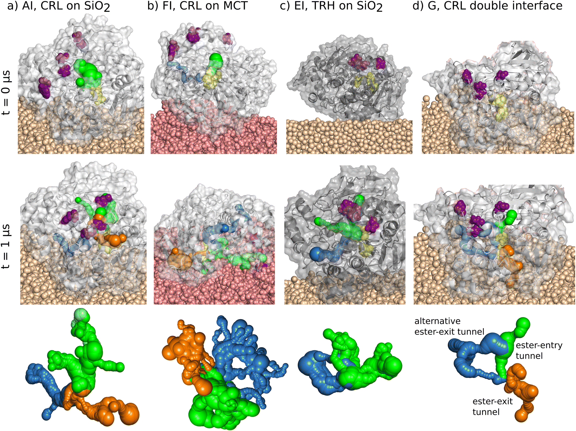
| | Fig. 1 Snapshots of all classes of simulated systems with the naming scheme of Table 1. Systems A, B, C, D, F and H contain the open state of the LIP1 (PDBID: 1CRL). Systems E and G contain the closed state of LIP1 (PDBID: 1TRH). Index 0 refer to the reference LIP1 systems in solution. For the immobilized proteins on SiO2 consequently the starting structure is plotted. The MCT system (FI–III) displays the starting and the final structure after diffusion through the oil phase during MD. The proteins are displayed as new cartoon structure with their corresponding isopotential surfaces at 5kBT (blue) and −5kBT (red) calculated with the Poisson–Boltzmann-solver.53 Index I–III mark the same protein orientation on the substrate at different substrate locations. 1CRL is displayed with a light grey new cartoon structure and a transparent vdW surface. 1TRH is presented in a darker grey tone, respectively. The LID residues are highlighted in purple as vdW balls, the catalytic triad residues in yellow. The orientation of the proteins is highlighted with the plotted dipole arrow with a color gradient from red (negative) to blue (positive) calculated within Gromacs.33 | |
3.1 Adsorption of LIP1 to single interface systems
3.1.1 Adsorption to silica.
For 1CRL the protein side with a high negative charge density is side facing away from the silica surface for all the attractive starting orientations identified on SiO2 (see Section 2.2). We have simulated a total of six different systems with open-state configurations in four different protein orientations (Fig. 1). For systems AI, AII AIII, C, and D, the initial orientations show the protein dipole parallel to the surface. In system B, the dipole points towards the surface. For the closed state configuration, no attractive orientation has been identified, which can be explained by the pronounced negative surface charge distribution on the protein surface. We have aligned the 1THR structure with the 1CRL starting orientation of system A as the initial orientation and used this for three independent simulations (EI to III).
All simulated systems have shown stable adsorption configurations during the simulation time of up to 1 μs. In Fig. 2(a) and (b), the final adsorption configurations after 1 μs of simulation time are presented as representative molecular snapshots for all adsorbed systems. In Fig. 2(e) and (f), all amino acids connected to the silica surface are plotted on one-dimensional contact maps over the simulation time. The transparent bar in (a) and (b) labels the area we have evaluated for the contact maps. Each amino acid within 5 Å above the surface is listed in the plot. A green (1CRL) and blue (1TRH) signal is set below a cutoff distance of 2.7 Å for each frame for the closest heavy atom of the corresponding amino acid (Fig. 2(e) and (f)). A complete list of contact maps for all systems with immobilized lipase can be found in the ESI† (Section S0.1). Here, all amino acids with contact signals for more than 30% of the plotted frames are listed below the plot. Amino acids that are found to be permanently adsorbed (more than 90% of the frames with color signals) are listed in bold letters. For the systems AI–III and EI–III with equal starting orientations, consistent contact groups at ARG324/GLU325, SER496/SER498 and ASP523/SER527 are observed in all six simulations. In addition, further charged and polar amino acids are found in three to five systems, respectively, which surround the key contacts.
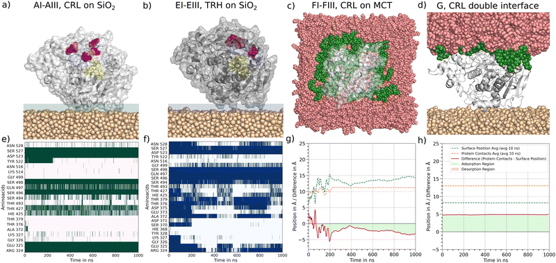 |
| | Fig. 2 Adsorption of 1CRL and 1THR at silica and MCT. In (a) to (d) molecular snapshots of the final configurations of the adsorbed systems are plotted. The silica surface is marked as salmon colored vdW balls, the MCT surface is colored as rose. The protein is displayed according the coloring scheme of Fig. 1. (e) and (f) For adsorption at silica all atoms of the protein with a distance cutoff of 5 Å to the surface are analyzed in contact maps over time. In each frame with a distance lower than 0.27 nm for any heavy atom between an amino acid and a surface atom, a colored (1CRL, green and 1TRH, blue) signal occurs. (g) and (h) The z position of 1CRL (dashed orange line) and the MCT phase (dashed blue line) is plotted over time. The difference between them is plotted with the solid red line. The area below the graph is marked in transparent red for positive Δz values corresponding to desorption, for negative Δz values in transparent green corresponding to adsorption. | |
The systems B, C and D with varying starting orientations reveal alternative contact groups within the protein sequence (Section S0.1, ESI†). In system B numerous stable contacts over the entire simulation time are identified for the contact groups (GLY111/ALA112/ASN113), (ASP199/THR201/LYS202), (THR476/ASP477/LEU478/ASP479/ASN481/THR482) and (LYS488/GLU491) and the individual contacts LYS231, ARG235 and THR430. The total number of contacts is significantly higher for system B in comparison to AI–III. However, the distribution of amino acid side chains involved in the formation of contacts is positively charged and negatively charged or polar, as in the AI–III systems. The nonpolar contacts found for GLY and ALA results from the neighboring amino acids of the main contacts listed above. In general, for the 1CRL systems B to D with different starting orientations, the contacts observed differ in their sequence number but reveal the same chemical character. A detailed list of contacts for these systems is displayed in Table S2 (ESI†).
3.1.2 Adsorption to MCT oil.
In all three systems with 1CRL at the oil–water interface, the protein undergoes rotation while diffusing to the surface, and eventually orients the ester-entry tunnel near the LID residues towards the oil phase. Fig. 1, FI–III shows the representative adsorption configurations after 1 μs of simulation time. These orientations differ substantially from all favored adsorbed states identified on the silica surfaces, and we can therefore assume that there will be no competition for adsorption sites in oil–protein–silica systems. In contrast to the well-defined contact points observed on silica, the adsorption of 1CRL at MCT is driven by less specific hydrophobic interactions. In Fig. 2(c) the top view of a representative snapshot of an adsorbed state highlights in green all MCT molecules in contact with the protein. It can be seen that the radius of MCT molecules is larger than the radius of the protein. In Fig. 2(g) we have analyzed the difference Δz of the z coordinate of all amino acids on the adsorbed side (orange dashed line) and the z coordinate of MCT molecules (blue dashed line) which are labeled green in Fig. 2(c) over time. In the beginning of the time plot, the total Δz (red line) oscillates around zero. Values above zero mean desorption and below zero mean adsorption. After 100 ns, adsorption with higher oscillations until 200 ns can be observed. Here, the MCT molecules rearrange themselves to find a stable encasing of the hydrophobic side of the protein. After 200 ns Δz shows a very smooth behavior, indicating a steady-state adsorption condition. Within the last 200 ns of simulation, the protein is embedded in the MCT phase up to a depth of about 3 Å. Noting that the calculated radius of gyration of 1CRL is 2.24 nm and of one MCT molecule about 0.5 nm, this means that a significant hydrophobic part of the protein is encased by MCT molecules. Compared with the isosurface potential of Fig. 1(A0), this is reasonable, as we have seen a strongly hydrophobic protein surface around the ester-entry tunnel and only a spot with a higher negative surface charge density at the location of the LID residues. In the Section S0.1 (ESI†), all Δz plots for FI to FIII are listed in Table S2 (ESI†). For every system, oscillations are visible at the beginning. All systems find their steady-state condition after about 200 ns with different depth values from 1 to 3 Å for the protein encasing in MCT.
We note that the encasing depth is not necessarily correlated with a more effective substrate penetration into the enzyme's interior. In fact, we observed the spontaneous insertion of one MCT molecule into the ester entry tunnel only in the case of the FIII system, which shows the shallower encasing depth (Fig. 3). In contrast, the conformation of the LID region does affect the interaction with MCT, as revealed by the fact that no stable adsorption or encasing could be observed for the closed conformation of the LIP1 molecule (1TRH). We assume that blocking the strongly hydrophobic side via the LID residues increases the areas of negative charge density on the molecular surface (Fig. 1(E0)), thus hindering the interaction of the protein with the hydrophobic MCT surface.
 |
| | Fig. 3 Molecular snapshot of the system FIII at 1000 ns. MCT surface is displayed as rose vdW balls, the protein with grey new cartoon structure and transparent vdW surface, the catalytic triad is presented with yellow vdW balls. One MCT molecule of the oil phase enters the ester-entry tunnel of 1CRL and is highlighted as pink vdW balls. | |
3.2 Flexibility of the lipase
The strong adsorption of 1CRL and 1TRH at the silica surface and significant encasing in the MCT phase motivate an in-depth investigation of the structural stability of the immobilized systems. In this section, we present a detailed analysis of the enzyme flexibility, as quantified by the RMS fluctuations of each amino acid in the sequence of the immobilized enzymes with respect to the free enzyme in solution. The most representative RMSF plots are reported in Fig. 4, and all other RMS analyses are reported in the ESI,† Fig. S3. The amino-acid-resolved B factors obtained in the MD simulations are plotted on the corresponding proteins in the new cartoon structures next to each panel. A color gradient from white (no fluctuation) via orange (moderate fluctuations of about 0.5 nm) to red (high fluctuations of up to 1 nm) represents the most flexible zones within the protein. For the open state conformation in solution (A0), a low RMSF was observed for the entire sequence of the globular protein, except for the LID region (amino acide 65 to 90). This peak of structural flexibility for the exposed helix (Fig. 4, molecular snapshots) can be observed also for immobilized 1CRL on silica (systems AI–III, B, C, D) as well as on MCT phase (FI–III). In 1TRH, the LID region does not show the same flexibility, neither for the protein in solution (E0), nor for the immobilized one (EI–III). It is conceivable that the conformational change of the LID region of 1TRH that leads to the blocking of the ester entry tunnel stabilizes the overall LID helix. For immobilized 1CRL (system AI–III) another peak occurs around position 450 in the sequence, which involves the amino acid HIS449 of the catalytic triad (SER209–HIS449–GLU341). This peak was not observed for the other adsorbed orientations (B)–(D) on silica, nor for immobilization on MCT. In summary, the most flexible enzyme regions are consistently located in correspondence of sequences that are pivotal for the enzyme activity or inactivity, namely the LID region and the catalytic triad. A detailed analysis of both these regions is thus required to draw conclusions about the catalytic activity of immobilized open-state lipases, as carried out in the next section.
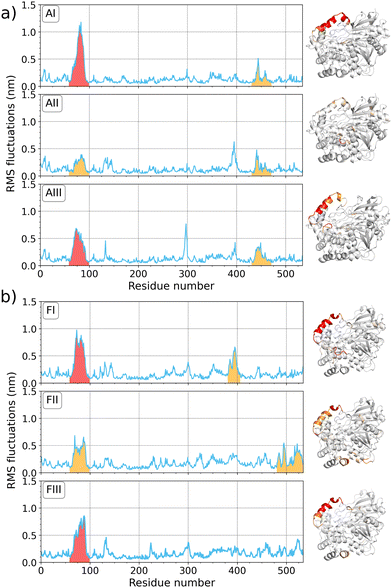 |
| | Fig. 4 Root mean square fluctuation (RMSF) plots for immobilized 1CRL on (a) silica (system A) and (b) MCT phases (system F) over the whole protein sequence of 534 amino acids, each for three individual simulations (I–III). On the right side of the corresponding plots, a molecular snapshot in new cartoon structure is colored according the amino-acid-resolved B factor with a gradient from white to red (0 to 1 nm). Peaks in the RMSF plots are colored with respect to the coloring scheme of the molecular snapshot. | |
3.3 Analysis of the catalytic triad of immobilized lipases
The catalytic mechanism of lipase involves the action of an acid–base-nucleophile triad for the hydrolysis of MCT molecules. In LIP1, GLU341 acts as the acid that polarizes the base HIS449, which in turn activates the nucleophile SER209. The resulting serine is highly reactive and induces splitting of the ester bond in the triacylglyceride molecules. The exchange of the proton between the individual amino acids is essential for the catalytic activity of 1CRL and can be ensured only when the X-H⋯X′ distances between the individual side chains are in the order of magnitude of hydrogen bonds.54 Therefore, it is essential to prevent irreversible structural changes within the catalytic triad upon adsorption at material surfaces. In Fig. 5, the evolution of the distance X–H⋯X′ between the closest atoms of SER209–HIS449–GLU341 are plotted for all simulated immobilized 1CRL molecules. The distances of the catalytic triad for 1CRL in solution and all simulated 1TRH systems can be found in the ESI,† Fig. S1. Based on Voet et al.,54 stable connections in the catalytic triad are defined for SER209(OH) to HIS449(ND/NE) and HIS449(ND/NE) to GLU341(O) up to 0.3 nm. It is quite obvious that in almost all 1CRL systems apart from (B), the distance between SER209 and HIS449 (yellow line in Fig. 5) fluctuates between levels of 0.22 nm and 0.56 nm (in system AIII up to 0.7 nm) independently of the surface. This means that the proteins fluctuate between conformations in which protons could in principle flip to the neighbored amino acid (0.22 nm) and other conformations where the proton exchange cannot take place. Remarkably, system B is the only one with a different dipole orientation than in A, C, and D. In system B, a stable SER209–HIS449 distance of about 0.22 nm is observed for the whole simulation time, as also found for the reference systems in solution and for the immobilized 1THR on silica (Fig. 5 and Fig. S1, ESI†). The fluctuations in AI–III, C and D are less frequent for the HIS449–GLU341 distances, but often related to a previous increase of the SER209–HIS449 distances. The jumps between these distances are associated with a flip of the histidine side chains, as visualized in Fig. 5(d)–(g) for different time frames, breaking the distinct ideal line of the three amino acids (shown in Fig. 5(d)). Analysis of the developments of protein contacts to their underlying surface (Fig. 2 and Section S0.1, ESI†) does not reveal any correlation of the formation or loss of surface contacts with the flip of HIS449 in the catalytic triad. However, the flips are found to be reversible within the time frame of our simulations for all but one system (AII) and the distance of the two outer amino acids (SER209 and GLU341, rose line in Fig. 5) is found to be stable at 0.7 nm. A consistent check of the distances of the Cα atoms of the corresponding three amino acids reveal no significant changes. We thus speculate that the dynamics observed for HIS449 are neither crucial for the overall catalytic activity20–22 nor explain the increase of stereo selectivity.23–27 Rather, in line with the discussion in ref. 29, we investigate the influence of immobilization of the conformation of the LID region.
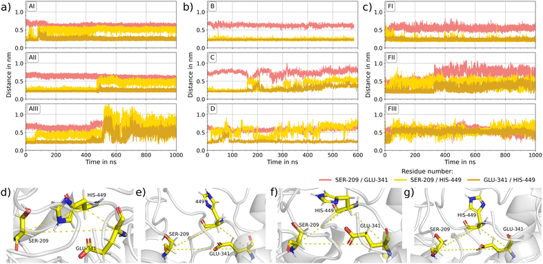 |
| | Fig. 5 Catalytic triad: (a)–(c) the evolution of the distances of SER209–HIS449 (yellow), HIS449–GLU341 (ocre) and SER209–GLU341 (salmon) of immobilized 1CRL over the simulation time are plotted. (a) For different locations of adsorption on silica (AI–III), (b) for different orientations of adsorption on silica (B)–(D) (c) for three independent simulations of 1CRL encased by MCT molecules (FI–III). (d)–(g) Molecular snapshots of the catalytic triad in system D at (d) 0 ns, (e) 150 ns, (f) 250 ns and (g) 500 ns are shown. The Cα atoms of SER209, HIS449 and GLU341 are connected with a dashed line. The formed triangle reveals consistence for all four snapshots. | |
3.4 Analysis of the LID residues of immobilized lipases
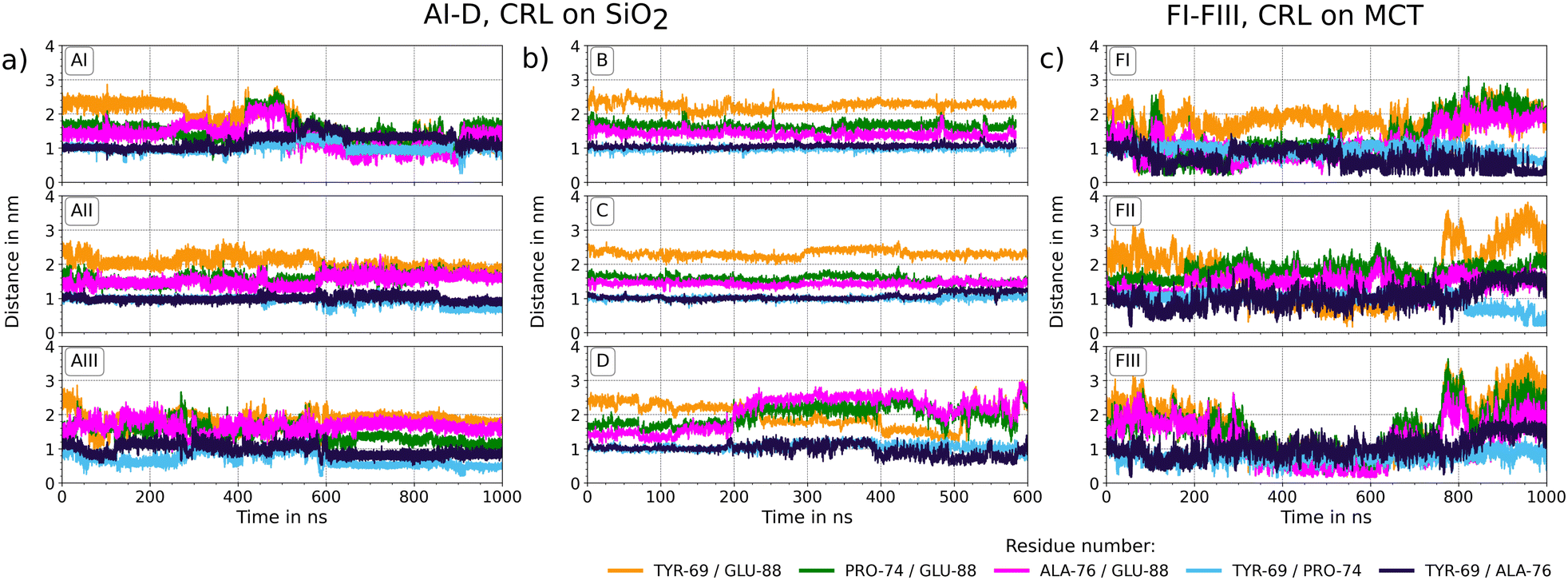
The stability of the LID region of adsorbed closed (1TRH) and open (1CRL) lipase at the SiO2/water and MCT/water interfaces is studied in up to 1 μs long MD simulations and will be discussed with reference to the corresponding solvated systems. In a first step, we have analyzed the protein network that stabilizes the LID domain in snapshot contact maps of the final configurations of each protein system. In Fig. 6 contact maps of the amino acids are shown throughout the protein sequence and as zoom into the LID domain for the representative systems 1CRL (D) and 1TRH (EIII) immobilized at SiO2. Zoomed contact maps for all systems are shown in the ESI,† Fig. S3. In the zoomed-in contact maps, all patterns which occur consistently in all systems of the corresponding open-state and closed-state conformations are highlighted with transparent colored bars and will be discussed in detail in the following. The contact map of system D is highlighted with a violet transparent bar in Fig. 6(a). It consists of residues PRO65 to GLU70, which are in close proximity of the LID region and are connected to PRO294 to ALA298 in the protein body. The snapshot of the LID region of system D (Fig. 6) shows that the LID residues are very exposed and are only connected to the protein body at a single end. They present no specific secondary structure motif, but form a flexible coil. This observation holds for all 1CRL systems, both in solution and immobilized (Fig. S3, ESI†), and is consistent with the RMSF plots that show the highest flexibility in the LID region. In addition, two patterns are visible for 1CRL in system AI (Fig. S3, ESI†) that could not be observed in all other immobilized open-state conformations. These pattern will be discussed separately in the Section 3.7 dedicated to the double interface system G. In the zoomed contact map of system EIII, highlighted with red bars in Fig. 6(b), three patterns emerge that are observed for all the closed-state conformations (Fig. S3, ESI†). The first pattern comprises the amino acids PRO65 to TYR69 in the LID-near region, which are connected to the amino acids GLY295 to TYR299 in the protein body. This pattern is almost consistent with the open-state conformation, and we assume that no effect on the conformational change between the active and inactive states is exerted in that interaction zone. The second pattern shows two signals in one column and addresses the amino acids GLY67 to TYR69 and ASN72 to PRO74 in the LID region which are connected to the same region in the protein body, namely the residues PHE344 to SER348. Specific interactions are THR68/SER348, TYR69/THR347, and LEU73/PHE344. Here, TYR69 is directly involved in the interaction network and was named as one of the determining amino acids in the LID region in the work of Grochulski et al.17 This pattern is present for all 1TRH systems independently of the immobilization, and therefore we classify it as specific to stabilize the inactive form of LIP1. The third pattern is formed by ALA76 to LEU78, LEU80 to MET82, and SER84 to GLU88 in the LID region to the amino acids LEU442 to SER450 in the protein body. These regions contain a high amount of hydrophobic amino acids that stabilizes the interaction pattern. HIS449, which acts as the base in the catalytic triad, is surrounded by interacting residues in the protein body and is sterically blocked by the amino acids SER84, VAL86, and PHE87 of the LID near region. This contact formation induces conformational stabilization of the LID helix, which is clearly visible in the molecular snapshot of system EIII in Fig. 6(b). The helix, which is formed in the inactive state only, lies above the triad residues and closes the entrance to the ester entry tunnel. With this analysis of all contact patterns in the LID near region, we can understand the influence of each single residue on the stabilization of the active and inactive forms of LIP1. We could show that different patterns are present for active and inactive proteins, but no information was so far given on the time evolution and vibrational dynamics of the LID residues. GLU88 was rarely present in the contact pattern discussed so far. As the residue is found to be specifically responsible for the conformational change between the active and inactive state,17 further insight into its dynamics is provided by the analysis of the individual distances between the LID residues for the open and closed conformations. The distances of the LID residues of immobilized 1CRL are plotted in Fig. 7, those of 1TRH and the solvated references can be found in the ESI,† Fig. S2. In comparison with the open and closed state of LIP1, the distances of TYR69–ALA76, ALA76–GLU88 and PRO74–GLU88 are the same at the beginning of the simulations. Despite that, the TYR69–GLU88 and TYR69–PRO74 starting distances are larger for the open-state conformation. However, during the dynamics, it can be observed that the fluctuations within 1CRL (A0) are significantly larger than in 1TRH (E0) for all distances except for PRO74–ALA76. This applies also to the systems immobilized on silica. The LID distances for 1TRH on silica (systems EI–III in ESI,† Fig. S2(b)) show stable values around their starting values. The 1CRL systems on silica show significant changes (Fig. 7(a) and (b)). However, the distribution and magnitude of the changes depend on the orientation of the surface adsorption. The AI–III and D systems show larger changes than the B and C systems, with almost constant values. In AI and D, a significant decrease in the TYR69–GLU88 distance and a strong oscillation of PRO74–GLU88 and ALA76–GLU88 to higher distances can be observed. GLU88 is consistently involved in the observed changes. However, this cannot be correlated with the position of the LID residues toward the solvent or the surface, because the LID of systems A and B is oriented toward the solvent and the LID of C and D is oriented rather toward the silica surface (Fig. 1). The decrease of TYR69–GLU88 for two of the six investigated systems (namely AI and D) could be consistent with at least a partial deactivation of the enzyme. However, the position of the LID at the end of the simulation is still quite different from that in the closed conformation (cf.Fig. 2). During 1CRL adsorption to the MCT phase, the LID residues undergo significant structural rearrangements (Fig. 7(c)). In the systems FI–III, all the distances containing GLU88 are involved. During the approach phase (up to about 200 ns according (Table S2, ESI†)), the distances between the residues TYR69–GLU88, ALA76–GLU88, and PRO74–GLU88 decrease significantly and stay very close during the embedding of the protein in the MCT phase (from 200 ns to about 800 ns). This can also be observed for ALA76–GLU88 and PRO74–GLU88 in AI and for TYR69–GLU88 in AII. In the last 200 ns, when lipase is stable in contact with MCT, the LIDs are widely open, with all distances increasing above their starting values except for the 69–74 pair. In summary, the flexibility of the LID region is significant in both the solvated and the immobilized states, and is larger in the open than the closed state conformation. However, the changes in the distances in the MCT systems also show that a sequential opening of certain residues may occur in response to the solvent environment, and is only marginally affected by surface adsorption. The sequential change and its putative impact on the catalytic activity will be further evaluated with respect to the accessibility of the catalytic triad and substrate conversion with docking simulations.
 |
| | Fig. 6 Protein contact maps of the final configurations of selected systems of (a) 1CRL (system D) and (b) 1TRH (system E) immobilized on silica. For each system, a contact map with the full protein sequence, a zoom into the LID near region PRO65 to VAL90 over the full protein sequence and a zoom of the LID near region over the corresponding contacts in the protein body are displayed (from left to right). Violet transparent bars highlight specific pattern within the LID region with the protein body for the active state of LIP1, red transparent bars for the inactive state of LIP1. The molecular snapshots next to the contact maps rely to the colored pattern respectively. The protein is illustrated in a gray, transparent new cartoon structure. The catalytic triad and the LID residues are marked as yellow and purple CPK model, respectively with a scale factor of 2. Amino acids of the LID region of the contact pattern are highlighted in a purple liquorice model, the contact partner in the protein body as liquorice model with residue type naming scheme (polar in green, unpolar in white). | |
 |
| | Fig. 7 Distance plots of the LID domain in immobilized 1CRL. The distance of the specific residues TYR69, PRO74, ALA76 and GLU88 comprising the LID domain in lipase1 is plotted over the simulation time for all simulated systems of (a) and (b) 1CRL on SiO2 and (c) 1CRL on MCT. | |
3.5 Accessibility of the catalytic site of immobilized lipases
In order to catalyze an enzymatic reaction, the accessibility of the catalytic site and binding of substrates to the triad residues have to be guaranteed. The pathways along which substrate molecules can diffuse from the outer surface of the enzyme to the buried catalytic site are predicted using tunnel calculations.50 The results are presented in Fig. 8. Tunnels with entrances close to or around the lid, which is the natural ingress location of the lipase substrates, are colored green (entry tunnels). Tunnels that connect the catalytic triad to the exit location of the ester product after catalytic conversion, as identified by Foresti et al.,55 are colored orange. Other statistically relevant tunnels are colored blue. It turns out that in solution, the ester exit tunnel of 1CRL fluctuates quite strongly, whereas the ester entry tunnel is significantly more stable. We could assume that the exit tunnel structure will be stabilized as soon as a cleaved fatty acid passes through it. For 1TRH, the entrance tunnel could only be seen in a few snapshots. This led to a starting structure of immobilized 1TRH without visible tunnel, indirectly confirming the validity of the simulation protocols and parameters (Fig. 8(c)). The starting immobilized open structure 1CRL, instead, presents an entry tunnel connecting the hydrophobic side of 1CRL to the catalytic triad. The LID region (shown in purple) is leaned away from that region, confirming the active state of the lipase in this conformation (Fig. 8(a)). After 1 μs of simulation, tunnels could be found for both SiO2-adsorbed structures, as shown in Fig. 8(a) and (c). Interestingly, only the 1CRL structure presents the exit tunnel proposed by Foresti et al.55 However, both structures present a further tunnel composed by the residues ASN176, LEU179, LYS180, MET213, VAL245, SER247, ARG303, LEU304, SER305, TYR306 LEU307, PRO308, ARG309, PRO310, ASN314 and ILE315 (shown in blue). This tunnel can be interpreted either as an alternative binding site of the substrate to the lipase, or, most appropriately, it can be considered as an alternative exit tunnel for the ester products. Tunnels were also calculated from ten snapshots from the last 50 ns of each simulation and were considered statistically relevant if they were present in at least three or more of these snapshots (Tables S4 and S5, ESI†). To graphically render the tunnel time evolution, they are plotted together as a transparent cloud for all time frames, apart from the selected snapshots, in which they are plotted as an opaque structure. Compared with the enzymes in solution, both immobilized lipases offer stable tunnel networks. In 1TRH the network is significantly smaller with one ester entry tunnel and one ester exit tunnel. However, with the blocked catalytic triad (Fig. 6(b)), no ligand can pass the tunnel. In 1CRL, the entrance, the proposed and the newly evaluated exit tunnel are stable throughout the simulation time (Tables S4 and S5, ESI†). Therefore, we can safely conclude that adsorption at the SiO2 interface may positively influence the enzymatic activity for two reasons. First, the adsorbed configurations present stable tunnels for substrate ingress, even when starting with an initially closed LID (1TRH, system EI) or after partial closure of the initially widely open LID (1CRL system AI), as noted above (see Fig. 8). Second, an alternative tunnel for product egress could be identified in the adsorbed structures, which may contribute to increase the catalytic turnover rate.
 |
| | Fig. 8 Visualization of ester-entry and -exit tunnels for (a) 1CRL on SiO2, (b) 1CRL on MCT, (c) 1TRH on SiO2 and (d) 1CRL with both interfaces at t = 0 μs and t = 1 μs of MD simulations. LID and catalytic triad residues are shown in purple and yellow, respectively. In the bottom line the average tunnel structures computed from snapshots taken at every 5 ns in the final 50 ns of simulation are shown. Entry tunnels are colored in green, previously suggested ester-exit tunnels55 in orange and newly predicted tunnels in blue. | |
3.5.1 Accessibility of the catalytic site on MCT.
The accessibility to the active center is again investigated using tunnel calculations (Fig. 8(b)). In the adsorbed configuration, the entrance tunnel (shown in green) faces toward the MCT oil, with the LID residues (purple) deeply sunk into the oil phase. Therefore, substrate molecules can be directly extracted from the interface. The ester-exit tunnel proposed by Foresti et al.55 (orange) connects the catalytic site with the outer lipase surface above the interface. In addition, the alternative ester-exit tunnel (blue) is again revealed, which connects the catalytic site equally to another region of the outer lipase surface above the interface. All of these tunnels are statistically and stably open, as shown in Fig. S4 (ESI†). They undergo rather large variations of their position during the simulation, which may be related to a larger flexibility of the oil–water interface.
3.6 Substrate binding
3.6.1 On silica.
Further arguments towards the activity and the (enantiomeric) selectivity of the free and SiO2-immobilized lipase can be drawn from docking simulations with a variety of triacylglycerid molecules (see Methods, Section 2.4). The results are presented in Fig. 9 using PoseView.49 Tricaprylin (or briefly C8–C8–C8) could be successfully docked to the catalytic site of the open 1CRL structure (Fig. 9). The molecule's side chains are stabilized by a number of hydrophobic interactions, in particular via SER209, which is the nucleophile residue in the catalytic triad. The hydrophilic head forms hydrogen bonds with THR132 and GLY129. However, no successful docking could be obtained for C8–C8–C8 to the SiO2-adsorbed lipase. Instead, the C6–C8–C10 molecule is docked to 1CRL both before (Fig. 9(b)) and after (Fig. 9(c)) adsorption to SiO2, but in rather different binding poses. In the former case, a hydrogen bond is formed with GLU208, and the side chains do not face the catalytic triad. In the latter case, the C10 chain faces the catalytic triad and is stabilized by hydrophobic interactions with SER209 and GLY123. Hydrogen bonds are formed with ASN451 and GLU88, one of the LID residues that showed the most significant movement in our MD simulation (see Fig. 7). Interestingly, the enantiomer of the C6–C8–C10 structure did not show any stable docking pose with the SiO2-adsorbed structure. The above results indicate that adsorption of lipase to the SiO2/water interface induces a reorientation of the LID residues, which in turn modulates the binding selectivity and enantioselectivity toward MCT substrates. This is in line with the experimental literature,56 in which the enantio selectivity could be modulated by mutation of amino acids in the LID region.57,58 Our simulations particularly point to an important role played by ASN451, GLU208 and GLU88 in positioning the substrate inside the binding pocket of the adsorbed enzyme by hydrogen bonds. Special emphasis should be put on GLU88, because it belongs to the LID region.
 |
| | Fig. 9 Two-dimensional representation of triacylglyceride substrate binding to the open (1CRL) lipase before (0 ns) and after (1 μs) adsorption to SiO2. Hydrophobic interactions are depicted in green, hydrogen bonds are shown as dashed lines. The representations were created with PoseView.49 (a) Substrate binding of MCT (C8–C8–C8) to 1CRL at 0 ns, (b) substrate binding of MCT (C6–C8–C10) to 1CRL at 0 ns, (c) substrate binding of MCT (C6–C8–C10) to 1CRL adsorbed to silica/water interface at 1 μs, (d) substrate binding of MCT (C6–C8–C12) to 1CRL adsorbed to silica/water interface at 1 μs. | |
3.6.2 Substrate binding on MCT.
Docking simulations of MCT molecules to adsorbed lipase at the oil/water interface reveal that tricaprylin (C8–C8–C8) binds to it facing the catalytic site and is stabilized, in particular, by hydrophobic interactions with SER209, as already observed for free lipase (Fig. 10(a)). Hydrogen bonds are formed between the hydrophilic head of MCT and SER301. A similar docking pose within the catalytic site is obtained for the C6–C8–C10 molecule (Fig. 10(b)). In particular, in this case its enantiomeric form also docks to the oil-adsorbed lipase (Fig. 10(c)), although in a different pose, in which the C6 chain faces the catalytic triad and is stabilized by interaction with SER209. MCT with longer chains than C10 could not dock favorably with lipase. This indicates a lower (enantiomeric) selectivity of lipase adsorbed to oil than when adsorbed to SiO2 (see previous section).
 |
| | Fig. 10 Two-dimensional representation of triacylglyceride substrate binding to the open (1CRL) lipase before (0 ns) and after (1 μs) adsorption to MCT oil. Color codes as in Fig. 9. (a) Substrate binding of MCT (C8–C8–C8) to 1CRL adsorbed to MCT/water interface at 1 μs, (b) substrate binding of MCT (C6–C8–C10) to 1CRL adsorbed to MCT/water interface at 1 μs, (c) substrate binding of MCT (C6–C8–C10 enantiomer) to 1CRL adsorbed to MCT/water interface at 1 μs. | |
3.7 Analysis of the immobilized open state lipase in contact with the oil phase
So far, we could show that successful immobilization of 1CRL on silica leads to changes in the dynamics of the LID regions, but these changes do not appear to critically affect enzyme activity due to the high flexibility preserved in the region. HIS449, as one of the residues of the catalytic triad, shows notable flips of the side chain. However, the formation of entrance and exit tunnels and the coupling of several MCT ligands in docking simulations reveal stabilization of the active form for immobilized enzymes. All simulations with MCT phases are in line with experimental observations. Although the results are consistent for all SiO2 and MCT systems, analysis of the two-dimensional contact maps reveals the formation of two additional patterns in the AI system (Fig. S3, ESI†), which address the same residues in the protein body but are shifted in their sequence numbers for the residues of the LID domain compared to closed state. This configuration is expected to be representative of the experimental situation in which MCT emulsions are pressured through ceramic membranes functionalized with immobilized lipase. We expect that the strain associated with the flow of the emulsion could induce partial changes, as observed for system AI. Therefore, in the last step of our study we investigate how the immobilized system behaves dynamically in contacts with the MCT phase. To this aim, we simulate the interaction of an oil droplet with system AI immobilized on SiO2, illustrated in Fig. 1. It is consistent with our observation that lipase preferably adsorbs to SiO2 with the LID facing away from the interface, while oil favorably interacts with the hydrophobic region next to the LID region (see Fig. 1 and 2). The MD simulation starts with the final configuration of active (1CRL) lipase immobilized on SiO2 placed in direct contact with an oil droplet via the LID region (Fig. 1G). In Fig. 2h, the contact with the MCT phase is plotted over time and shows that the prepositioned droplet offers stable contact with the MCT phase from the beginning of the simulation. Fig. 11 shows a representative snapshot of the system after 1 μs of simulation (a) together with the corresponding one-dimensional contact map (b) and two-dimensional contact map (e). The protein is in contact with both silica and MCT over the whole simulation time. Whereas 1CRL is stably encased with a depth of about 5 Å in the MCT phase, the individual contacts estimated on the silica side are consistent with the contacts found for AI–III, namely SER527/ASP523, SER496, ARG324/GLU325. In addition, other surrounding amino acids adsorb stably for the whole simulation time (Fig. 11(b)), indicating good equilibration of the starting structure and no influence of the MCT droplet on the contacts to silica. Furthermore, the distances in both the LID residues and the catalytic triad residues remain fairly constant over 1 μs of simulation (Fig. 11(c) and (d)), respectively. Compared to single-surface systems, the fluctuations in distances between pairs of amino acids in these regions are always smaller, and no flipping of the HIS449 side chain is observed. A careful check of the two-dimensional contact map of system G (Fig. 11(e)) offer the additional contact pattern as in the initial structure to be stable for the entire simulation time (yellow bars). These signals reveal additional stabilization of the LID region, but offer a significantly different network in comparison to 1TRH. Whereas in the inactive form (system EIII), the residues GLY67 to TYR69 and ASN72 to PRO74 form the contact for the second pattern, in system AI and G, residues toward higher sequence numbers in the LID region, PRO74, LYS75, and MET82 form the contact to GLY346 to LEU350 in the protein body. Also in the third pattern, only residues ASP79 to LYS85 and PHE87/GLU88 offer contact signals to the amino acids ALA444 to PHE448. Due to that, the whole LID sequence in system G is shifted in a way that HIS449 cannot be sterically blocked. Rather, VAL81 is directly connected to PHE448 and VAL444 chelated by the side chains of ASP79 and GLN83 that hold the LID region in place. Instead, a direct approach of one MCT molecule to the entrance near the catalytic triad is visible (Fig. 11(e), molecular snapshots). This observation is in agreement with the analysis of the tunnel network which offers a narrower channel structure but in consistence with all other 1CRL simulations the presence of one stable ester entrance tunnel and two ester exit tunnel (Fig. 8(d)). This may suggest a stabilizing effect of the MCT phase on the structure of silica-immobilized lipases. In summary, the final distances and the overall lipase structure are very comparable to those of lipase adsorbed at the SiO2/water interface of AI–III (see Fig. 2(a), (e) and Table S1, ESI†). This indicates that oil droplets can interact with SiO2-adsorbed lipase without changing its conformation, which in turn would lead to catalytic activity and substrate binding selectivity similar to those in the absence of oil. Given the structural similarities with the cases already investigated, we did not perform further explicit analyses of accessibility tunnels or substrate loading poses.
 |
| | Fig. 11 Immobilized open state lipase in contact with the oil phase. Results of the doubled interface system with the final adsorption state of AI with a MCT droplet on top as starting configuration simulated for 1 μs. (a) Molecular snapshot of the doubled interface system SiO2/1CRL/MCT, established silica surface contacts of the contact map in (b) are highlighted as liquorice model and naming scheme. (c) Time evolution of the distances of residues SER209, HIS449 and GLU341 of the catalytic triad. (d) Time evolution of the distances of the LID domain, (e) protein contact maps of the final configurations of system G. A contact map with the full protein sequence, a zoom into the LID near region PRO65 to VAL90 over the full protein sequence and a zoom of the LID near region over the corresponding contacts in the protein body is displayed (from left to right). The violet transparent bar highlight the specific pattern within the LID region with the protein body for the active state of LIP1. The yellow bars highlight pattern, which are belong neither to the active nor the inactive form and occur upon immobilization of 1CRL at silica in system AI as the initial structure for system G only. The molecular snapshots highlight the interaction network of the corresponding pattern. The coloring scheme is the same like in Fig. 3. | |
4 Conclusions
In this study, we investigated the adsorption of lipase to silica–water and oil–water interfaces by means of classical molecular dynamics simulations. We were able to successfully immobilize both protein conformations on silica and identified fixed anchor points in the protein to the surface material, revealing no significant changes between the open and closed state conformation of LIP1. However, in all different orientations the substrate entry region (LID) is oriented toward the solvent, granting access to the catalytic triad of the enzyme. However, 1CRL and 1TRH show only minimal changes in their sequence, but exhibit fundamentally different behavior in the approach to MCT. Analysis of the surface potential of both enzymes offer explanations for the distinction between open and closed conformation.
1CRL is significantly more affine to oily liquid phases, as the protein surface has a larger hydrophobic surface due to the rearrangement of the LID region. The adsorption of MCT oil takes place with the LID region facing directly and strongly interacting with the oil, suggesting that substrates can be directly extracted from the interface.
A comprehensive contact analysis of the LID region in the protein has shown that in 1TRH the LID region is stabilized as a helical structure by defined contact patterns. This helix forces negatively charged glutamic and aspartic acid residues to be exposed to the polar solvent in a wide distribution and maximizes the surface area with a strong negative surface potential that is repulsive to the MCT phase. Stabilization of the LID helix leads to a steric blockade of the ester entry tunnel by the residues SER84, VAL86, and PHE87, which are firmly anchored in the helix and are not involved in the formation of the contact network with the protein.
In experiments, an increase of immobilized active lipases are explained by hydrophobic interactions. We could not confirm surface induced specific changes in the dynamics neither of the catalytic triad nor the formation of the LID domain upon surface adsorption, independent of the surface. Rather, we confirm the appearance of an ester exit tunnel as proposed by Foresti et al.,55 and predict the appearance of another alternative exit tunnel, which was not formed in solution. The substrate accessibility tunnels showed the largest flexibility, with a widely open entry tunnel toward the oil and the two ester-exit tunnels connecting the catalytic triad toward the outer lipase structure far from the interface, hinting to a high enzymatic activity. This could potentially lead to high catalytic turnover rates for SiO2-adsorbed lipase. Although starting with a fully open LID conformation results in partial closure of the entrance during some of our MD simulation, tunnel calculations reveal that the catalytic triad still remains accessible. Nevertheless, the docking simulations show a marked selectivity of the SiO2-adsorbed lipase toward asymmetric MCT molecules with chain lengths of 6, 8 and 10 C atoms. The docking to SiO2-adsorbed lipase in only one of its enantiomeric forms, gives strong evidence for enhanced enantio selectivity after immobilization on silica. In the MCT systems, the docking simulations show less marked selectivity with respect to SiO2-adsorbed lipase and suggest different binding poses of the MCT substrates at the catalytic active site. However, docking of MCT molecules with hydrophobic chains longer than 10 C atoms was never observed and a clear limitation to medium chained MCT molecules is noticed. Due to favorable adsorption orientations to SiO2 and oil, silica-immobilized lipase can come in contact with oil droplets in a way that allows easy ingress of MCT molecules to the catalytic site. The exposure of the silica-adsorbed structure to an additional oil interface had no further impact on the enzyme's conformation, in particular on the distances among LID or triad residues, was observed. The set of simulations thus provides a molecular-level rationalization of the high activity and increased substrate selectivity of Candida rugosa lipase after immobilization on silica. This could be exploited in future application of lipase immobilized on ceramic membrane for triacylglycerides hydrolysis.
Author contributions
Patrick Giefer: conceptualization (lead); investigation (lead); writing – original draft (lead); writing – review & editing (equal). Udo Fritsching: funding acquisition (lead); supervision (equal); writing – review & editing (equal). Lucio Colombi Ciacchi: supervision (equal); writing – review & editing (equal). Susan Köppen-Hannemann: supervision (lead); conceptualization (equal); writing – original draft (equal); writing – review & editing (equal).
Data availability
All data from systems A0 to H are stored at https://doi.org/10.5281/zenodo.14844485. For each system, an all-atom coordinate file in gro format, a tpr file containing the simulation setup specifications, and a coordinate and trajectory file set (gro/xtc) with removed water molecules are available. In the uploaded trajectories, a sampling frequency of 100 ps and an accuracy of 2 decimal for each atom position are provided. The naming scheme is consistent with the naming scheme of the simulated systems. The analysis plots are consequently applied for all systems. In the manuscript, we show selected plots that represent the observations that are discussed in this work. All remaining plots are listed in the ESI.†
Conflicts of interest
The authors have no conflicts to disclose.
Acknowledgements
This project has been funded by the German Research Foundation (DFG) within the SPP 1934 “DiSPBiotech” under Grant No. FR 912/40. Computational Ressources were provided by The North-German Supercomputing Alliance (HLRN) under Grant No. hbi00037. We are thankful for the assistance of Daria Sazanovich for the creation of the TOC figure.
Notes and references
- P. Ferrer, J. L. Montesinos, F. Valero and C. Solà, Appl. Biochem. Biotechnol., 2001, 95, 221–256 CrossRef CAS PubMed.
- P. Chandra, Enespa, R. Singh and P. K. Arora, Microb. Cell Fact., 2020, 19, 1–42 CrossRef PubMed.
- J.-C. Chen and S.-W. Tsai, Biotechnol. Prog., 2000, 16, 986–992 CrossRef CAS PubMed.
- S. Benjamin and A. Pandey, Yeast, 1998, 14, 1069–1087 CrossRef CAS PubMed.
- L. Sarda and P. Desnuelle, Biochem. Biophys. Acta, 1958, 30, 513–521 CAS.
- R. Verger, Trends Biotechnol., 1997, 15, 32–38 CrossRef CAS.
- C. T. Hou, J. Ind. Microbiol., 1994, 13, 242–248 CrossRef CAS.
- A. Bastida, P. Sabuquillo, P. Armisen, R. Fernández-Lafuente, J. Huguet and J. M. Guisán, Biotechnol. Bioeng., 1998, 58, 486–493 CrossRef CAS PubMed.
- R. C. Rodrigues, J. J. Virgen-Ortíz, J. C. dos Santos, Á. Berenguer-Murcia, A. R. Alcantara, O. Barbosa, C. Ortiz and R. Fernandez-Lafuente, Biotechnol. Adv., 2019, 37, 746–770 CrossRef CAS PubMed.
- E. Wehtje and P. Adlercreutz, Biotechnol. Bioeng., 1997, 55, 798–806 CrossRef CAS PubMed.
- R. Wedberg, J. Abildskov and G. H. Peters, J. Phys. Chem. B, 2012, 116, 2575–2585 CrossRef CAS PubMed.
- P. Trodler and J. Pleiss, BMC Struct. Biol., 2008, 8, 9 CrossRef PubMed.
- L. F. García-Alles and V. Gotor, Biotechnol. Bioeng., 1998, 59, 684–694 CrossRef.
- S. Rehm, P. Trodler and J. Pleiss, Protein Sci., 2010, 19, 2122–2130 CrossRef CAS PubMed.
- P. Adlercreutz, Chem. Soc. Rev., 2013, 42, 6406 RSC.
- J. Barriuso, M. E. Vaquero, A. Prieto and M. J. Martínez, Biotechnol. Adv., 2016, 34, 874–885 CrossRef CAS PubMed.
- P. Grochulski, F. Bouthillier, R. J. Kazlauskas, A. N. Serreqi, J. D. Schrag, E. Ziomek and M. Cygler, Biochemistry, 1994, 33, 3494–3500 CrossRef CAS PubMed.
- J. Pleiss, M. Fischer and R. D. Schmid, Chem. Phys. Lipids, 1998, 93, 67–80 CrossRef CAS PubMed.
- P. Grochulski, Y. Li, J. Schrag, F. Bouthillier, P. Smith, D. Harrison, B. Rubin and M. Cygler, J. Biol. Chem., 1993, 268, 12843–12847 CrossRef CAS PubMed.
- A. Kumar, G. D. Park, S. K. Patel, S. Kondaveeti, S. Otari, M. Z. Anwar, V. C. Kalia, Y. Singh, S. C. Kim, B.-K. Cho, J.-H. Sohn, D. R. Kim, Y. C. Kang and J.-K. Lee, Chem. Eng. J., 2019, 359, 1252–1264 CrossRef CAS.
- E. Ranjbakhsh, A. Bordbar, M. Abbasi, A. Khosropour and E. Shams, Chem. Eng. J., 2012, 179, 272–276 CrossRef CAS.
- A. G. Cunha, G. Fernández-Lorente, M. L. E. Gutarra, J. V. Bevilaqua, R. V. Almeida, L. M. C. Paiva, R. Fernández-Lafuente, J. M. Guisán and D. M. G. Freire, Appl. Biochem. Biotechnol., 2008, 156, 133–145 CrossRef PubMed.
- D. Kahveci and X. Xu, Biotechnol. Lett., 2011, 33, 2065–2071 CrossRef CAS PubMed.
- Q. Zhang, J. Qian, H. Guo, W. Zhang and C. Kuang, J. Nanosci. Nanotechnol., 2020, 20, 6168–6172 CrossRef CAS PubMed.
- M. Mohammadi, Z. Habibi, S. Dezvarei, M. Yousefi, S. Samadi and M. Ashjari, Process Biochem., 2014, 49, 1314–1323 CrossRef CAS.
- C. Bernal, F. Guzman, A. Illanes and L. Wilson, Food Chem., 2018, 239, 189–195 CrossRef CAS PubMed.
- W. H. Yu, D. S. Tong, M. Fang, P. Shao and C. H. Zhou, J. Mol. Catal. B: Enzym., 2015, 111, 43–50 CrossRef CAS.
- U. Derewenda, A. M. Brzozowski, D. M. Lawson and Z. S. Derewenda, Biochemistry, 1992, 31, 1532–1541 CrossRef CAS PubMed.
- F. Secundo, G. Carrea, C. Tarabiono, P. Gatti-Lafranconi, S. Brocca, M. Lotti, K.-E. Jaeger, M. Puls and T. Eggert, J. Mol. Catal. B: Enzym., 2006, 39, 166–170 CrossRef CAS.
- N. López, M. A. Pernas, L. M. Pastrana, A. Sánchez, F. Valero and M. L. Rúa, Biotechnol. Prog., 2008, 20, 65–73 CrossRef PubMed.
- P. Grochulski and M. Cygler, J. Biol. Chem., 1993, 268(17), 12843–12847 CrossRef CAS PubMed.
- P. Grochulski and M. Cygler, Protein Sci., 1994, 3(1), 82–91 CrossRef CAS PubMed.
- M. J. Abraham, T. Murtola, R. Schulz, S. Páll, J. C. Smith, B. Hess and E. Lindahl, SoftwareX, 2015, 1–2, 19–25 CrossRef.
- R. Anandakrishnan, B. Aguilar and A. V. Onufriev, Nucleic Acids Res., 2012, 40, W537–W541 CrossRef CAS PubMed.
- H. Schestkowa, T. Wollborn, A. Westphal, A. M. Wagemans, U. Fritsching and S. Drusch, J. Colloid Interface Sci., 2019, 536, 300–309 CrossRef CAS PubMed.
- D. J. Cole, M. C. Payne, G. Csányi, S. M. Spearing and L. C. Ciacchi, J. Chem. Phys., 2007, 127, 204704 CrossRef PubMed.
- A. Butenuth, G. Moras, J. Schneider, M. Koleini, S. Köppen, R. Meißner, L. B. Wright, T. R. Walsh and L. C. Ciacchi, Phys. Status Solidi B, 2011, 249, 292–305 CrossRef.
- N. Hildebrand, S. Köppen, L. Derr, K. Li, M. Koleini, K. Rezwan and L. Colombi Ciacchi, J. Phys. Chem. C, 2015, 119, 7295–7307 CrossRef CAS.
-
L. Derr, Interactions between enzymes and oxide colloidal particles and their influence on enzymatic activity, VDI Verlag, 2016 Search PubMed.
- N. Hildebrand, M. Michaelis, N. Wurzler, Z. Li, J. D. Hirst, A. Micsonai, J. Kardos, A. Gil-Ley, G. Bussi, S. Köppen, M. Delle Piane and L. C. Ciacchi, ACS Biomater. Sci. Eng., 2018, 4, 4036–4050 CrossRef CAS PubMed.
- J. Sonnefeld, A. Göbel and W. Vogelsberger, Colloid Polym. Sci., 1995, 273, 926–931 CrossRef CAS.
- P. M. Dove and C. M. Craven, Geochim. Cosmochim. Acta, 2005, 69, 4963–4970 CrossRef CAS.
- L. Martínez, R. Andrade, E. G. Birgin and J. M. Martínez, J. Comput. Chem., 2009, 30, 2157–2164 CrossRef PubMed.
- B. Hess, H. Bekker, H. J. Berendsen and J. G. Fraaije, J. Comput. Chem., 1997, 18, 18–1463 CrossRef.
- W. F. van Gunsteren and H. J. C. Berendsen, Angew. Chem., Int. Ed. Engl., 1990, 29, 992–1023 CrossRef.
- T. Darden, D. York and L. Pedersen, J. Chem. Phys., 1993, 98, 10089–10092 CrossRef CAS.
-
L. Schrödinger and W. DeLano, PyMOL, 2020, https://www.pymol.org/pymol Search PubMed.
- W. Humphrey, A. Dalke and K. Schulten, J. Mol. Graphics, 1996, 14, 33–38 CrossRef CAS PubMed.
- K. Stierand, P. C. Maass and M. Rarey, Bioinformatics, 2006, 22, 1710–1716 CrossRef CAS PubMed.
- E. Chovancova, A. Pavelka, P. Benes, O. Strnad, J. Brezovsky, B. Kozlikova, A. Gora, V. Sustr, M. Klvana, P. Medek, L. Biedermannova, J. Sochor and J. Damborsky, PLoS Comput. Biol., 2012, 8, e1002708 CrossRef CAS PubMed.
- G. M. Morris, R. Huey, W. Lindstrom, M. F. Sanner, R. K. Belew, D. S. Goodsell and A. J. Olson, J. Comput. Chem., 2009, 30, 2785–2791 CrossRef CAS PubMed.
- M. D. Hanwell, D. E. Curtis, D. C. Lonie, T. Vandermeersch, E. Zurek and G. R. Hutchison, J. Cheminf., 2012, 4, 1–17 Search PubMed.
- E. Jurrus, D. Engel, K. Star, K. Monson, J. Brandi, L. E. Felberg, D. H. Brookes, L. Wilson, J. Chen, K. Liles, M. Chun, P. Li, D. W. Gohara, T. Dolinsky, R. Konecny, D. R. Koes, J. E. Nielsen, T. Head-Gordon, W. Geng, R. Krasny, G. Wei, M. J. Holst, J. A. McCammon and N. A. Baker, Protein Sci., 2017, 27, 112–128 CrossRef PubMed.
-
D. Voet, Fundamentals of biochemistry, Wiley, [Hoboken], 4th edn, 2016 Search PubMed.
- M. L. Foresti and M. L. Ferreira, Biomacromolecules, 2004, 5, 2366–2375 CrossRef CAS PubMed.
- Z. Zhao, D. Herbst, B. Niemeyer and L. He, Food Bioprod. Process., 2015, 96, 240–244 CrossRef CAS.
- S. Brocca, F. Secundo, M. Ossola, L. Alberghina, G. Carrea and M. Lotti, Protein Sci., 2009, 12, 2312–2319 CrossRef PubMed.
- M. Holmquist, M. Martinelle, P. Berglund, I. G. Clausen, S. Patkar, A. Svendsen and K. Hult, J. Protein Chem., 1993, 12, 749–757 CrossRef CAS PubMed.
|
| This journal is © The Royal Society of Chemistry 2025 |
Click here to see how this site uses Cookies. View our privacy policy here. 
 Open Access Article
 This Open Access Article is licensed under a
  *a,
U.
Fritsching
*a,
U.
Fritsching