
 Open Access Article
 This Open Access Article is licensed under a
 Creative Commons Attribution 3.0 Unported Licence
Defect dynamics in cholesterics: beyond the Peach–Koehler force†
Joseph
Pollard
 *ab and
Richard G.
Morris
abc
*ab and
Richard G.
Morris
abc
aSchool of Physics, UNSW, Sydney, NSW 2052, Australia. E-mail: joe.pollard@unsw.edu.au
bEMBL Australia Node in Single Molecule Science, School of Medical Sciences, UNSW, Sydney, NSW 2052, Australia
cARC Centre of Excellence for the Mathematical Analysis of Cellular Systems, UNSW Node, Sydney, NSW 2052, Australia
First published on 20th February 2025
Abstract
The Peach–Koehler force between disclination lines was originally formulated in the study of crystalline solids, and has since been adopted to provide a notion of interactions between disclination lines in nematic liquid crystals. Here, we argue that the standard formulation of this interaction force seemingly fails for materials where there is a symmetry-broken ground state, and suggest that this is due to the interaction between disclination lines and merons: non-singular yet non-trivial topological solitons. We examine this in the context of chiral nematic (cholesteric) liquid crystals, which provide a natural setting for studying these interactions due to their energetic preference for meron tubes in the form of double-twist cylinders. Through a combination of theory and simulation we demonstrate that, for sufficiently strong chirality, defects of +1/2 winding will change their winding through the emission of a meron line, and that interactions between the merons and defects dominate over defect–defect interactions. Instead of the Peach–Koehler framework, we employ a method based on contact topology—the Gray stability theorem—to directly calculate the velocity field of the material. We apply our framework to point defects as well as disclination lines. Our results have implications not just for chiral materials, but also for other phases with modulated ground states, such as the twist-bend and splay-bend nematics.
1 Introduction
Disclination lines are the fundamental topological defects of nematic liquid crystals in three-dimensional geometries. As centres of strong elastic distortion they are the dominant factor in the material's dynamics, and as such have been studied extensively.1–13 Amongst other things, they govern the isotropic–nematic transition and subsequent coarsening processes,14–16 as well as determine the behaviour of stable nematic textures, including their response to elastic stresses and external fields.17–19In crystalline materials, the standard approach to studying interactions between defects involves the Peach–Koehler force, an interaction force between disclination lines which is analogous to the Lorentz force in electromagnetism.20 It has since been adopted to describe the interactions between disclination lines in nematic liquid crystals.5,21 To apply the Peach–Koehler framework, we fix a set of defects and minimise the free energy subject to the constraint of the material having these defects. The resulting stresses and the Burgers vector of the disclination line are then used to compute the forces experienced by the disclination lines. It is also important to include additional forces, such as a line tension or terms coming from boundary conditions.13 Notably, this framework has been applied to study disclination motion in nematic materials in the one elastic constant approximation; a setting in which it has been very successful, yielding predictions that agree with simulation and experiment.10,12,13,22
However, to our knowledge, the predictions of this theory have not not been studied in depth in more complex settings, for example in materials where the single elastic constant approximation is strongly violated—for example, in lyotropic chromonic materials the elastic anisotropy lies at the heart of the interesting phenomenology, causing them to form chiral structures even though the molecules are not themselves chiral—or materials with broken symmetry in the ground state, such as cholesterics (chiral nematics)23 and twist-bend and splay-bend materials.24 In these cases, there are three broad challenges to applying the Peach–Koehler theory. First, at a practical level, there is difficulty in computing the minimisers of the energy, which is relatively straightforward in the one elastic constant approximation but not when there is elastic anisotropy or broken-symmetry terms in the energy. Second, and more fundamentally, non-uniform global structures selected for by the broken symmetry terms can also cause issues—for example, cholesterics select for helical winding in the director field, including along disclination lines, and this is not captured by the Peach–Koehler force. Finally, and most pertinent to this paper, these classes of material exhibit stable topological solitons, called merons and Skyrmions. In a recent paper, we described the topological and geometric aspects of defect–defect interactions, and showed that merons play a fundamental role in mediating interactions.25 Defect–meron interactions are not captured by the Peach–Koehler force, at least not in its standard formulation. Therefore, to go beyond the results of our previous work25—which focusses on topological and structural properties which are agnostic to the actual physics of these materials—we must understand the role that elastic forces play in these interactions.
The purpose of this paper is to begin an investigation of defect–defect and defect–meron interactions in materials that cannot be a approximated with one elastic constant. We choose to examine these issues in a particular class of materials, the chiral nematic liquid crystals, also called cholesterics. There are two key reasons why these are a convenient class of materials in which to study this problem. Firstly, chirality stabilises meron tubes in the form of ‘double-twist cylinders’, which are energetically favoured over a meron-free texture for sufficiently strong chirality26—thus, the issue of how merons interact with defects and mediate interactions between defects is of genuine practical importance in cholesterics. Secondly, the special topology of the cholesteric phase allows for their study via the machinery of contact topology,27–33 making them analytically tractable in a way that other classes of material are not.
The remainder of this paper is organised as follows. We review the topology of cholesterics in Section 2. By comparing the predictions of the Peach–Koehler theory with numerical simulations, we show in Section 3 that this theory appears not to give good predictions for the motion and behaviour of defects in a chiral material when the chirality is sufficiently strong; we see substantially different behaviour from an achiral system. Chiral disclinations with an initially +1/2-winding profile change their winding by the emission of a meron line (double-twist cylinder), and that a winding of the director profile along the disclination may cause it to buckle into a helix. This last case cannot be understood within the Peach–Koehler framework, as the Peach–Koehler force is entirely insensitive to profile winding.10 These observations suggest the Peach–Koehler interaction force between disclinations can be overcome by a force arising from the merons. Interestingly, merons were originally introduced in quantum chromodynamics to explain the phenomenon of quark confinement34—a similar effect occurs in cholesterics, with merons acting to screen interactions between disclination lines.
Instead of using the Peach–Koehler framework to analyse these materials, in Section 4 we adopt an approach based on contact topology. Under the assumption that the material maintains a consistent sense of handedness, the Gray stability theorem27,35 allows us to explicitly calculate the velocity field of the material. This technique has previously been applied to defect-free cholesterics,28 but we apply it to the case where the material contains disclination lines for the first time. We show that the predictions of this theory correspond much more closely to what is seen in simulation and experiment. Flow-field calculations show that meron tubes are driven to expand, and it is this which drives the motion of defects in a cholesteric, not Peach–Koehler-type interactions between the defects themselves. This behaviour appears generic in a cholesteric, and the change in winding of +1/2-lines appears to be the fundamental mechanism underlying the formation of double-twist regions from an initially random state.
One advantage to an approach based on contact topology is that it doesn't just allow for an analysis of disclination lines, but can also be applied to geometric structures such as cholesteric ‘layers’, topological solitons, and even point defects. In Section 5 we analyse the motion of a radial hedgehog defect in a droplet, and again show that our theory corresponds closely to what is observed in simulation and experiment-namely, that a radial hedgehog will displace from the centre of the droplet towards the boundary. In this particular example the material does not (and cannot29) maintain a consistent sense of handedness throughout the droplet or even in a neighbourhood of the defect. The fact that our technique still applies when this constraint is relaxed suggests that we may well be able to apply this framework to a broader class of materials which are of current experimental interest, for example lyotropic chromonics, as well as the twist-bend and splay-bend nematics. We close in Section 6 with a discussion of our results and the possibilities for future work.
2 Topology, elasticity, and the Peach–Koehler force in a cholesteric
Chiral materials furnish an especially rich source of topological and geometric phenomena, and liquid crystal materials comprised of chiral molecules (cholesterics) are no exception. In this section we review both the topology and the elasticity of these materials, and explain how the deceptively simple chiral symmetry-breaking leads to substantially different behaviour from an achiral material.The free energy for a cholesteric liquid crystal in the one elastic constant approximation is,
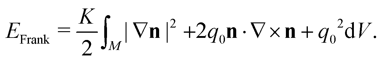 | (1) |
This energy favours nonzero twisting of the material, n·∇ × n ∼ −q0, with molecules rotating along a given direction p called the pitch axis.23,36 Making the assumption that the material is everywhere chiral, n·∇ × n ≠ 0, allows for an analysis of cholesterics using the machinery of contact topology,28–33 with results that compare well with simulation and experiment. In this work, we further develop the ideas of Machon28 to understand how chirality influences structural changes to defects during passive relaxational processes that involve minimising the free energy. We do not discuss the effect of hydrodynamics in this paper.
We remark that (1) is also the energy for a ferromagnet with the Dzyaloshinskii–Moriya interaction interaction, with n now a magnetic polarisation field. Since the magnetic field is orientable disclination lines do not arise in these materials, but merons, Skyrmions, and point defects (‘Bloch points’) do. Thus, some parts of our results will apply to these materials as well. There is a further potential application to superfluid phases of helium-3, which can form chiral structures and exhibit point defects, merons/Skyrmions, and string-like objects analogous to disclination lines.37,38
2.1 The contact topology of cholesterics and their disclinations
We briefly review the contact topology of chiral materials. The first key distinction between chiral and achiral materials is that the former have a binary, and global, topological invariant called ‘overtwistedness’. A cholesteric texture is overtwisted if it contains a ‘double-twist cylinder’, the core of which is a meron with +1 winding and a rotational structure—these are often referred to as ‘Bloch’ merons in the literature on magnetic systems.‡ A cholesteric texture is tight if no such structures exist in the material. The standard cholesteric helix,nq = cos![[thin space (1/6-em)]](https://www.rsc.org/images/entities/char_2009.gif) qzex + sinqzey, qzex + sinqzey, | (2) |
Correspondingly, disclination lines in cholesterics can be broken down into two topologically-distinct classes depending on whether a local neighbourhood is tight or overtwisted32—note that we can have disclinations that are locally tight inside a texture that is globally overtwisted, provided that any overtwisted disks are either entirely separate from the disclinations, or else have their boundary on the disclination line itself. The tight disclinations are exactly those that possess a well-defined winding number along the entire length of the line—that is, on any cross-sectional disk we can consider the winding of the director around the boundary of the disk, and for a tight disclination this number is constant and independent of the choice of disk.
Tight disclination lines arise in the majority of well-known cholesteric textures featuring defects, including meron lattices and blue phases. Note these textures are globally overtwisted because of the presence of double-twist cylinders, but the disclinations themselves are locally tight. Tight disclinations inside a globally tight texture can be generated in Grandjean–Cano geometries.39 The overtwisted disclinations have changes in winding, and will result from crossing tight disclination lines, for example.40 Examples of locally-overtwisted disclinations with attached meron tethers have been realised in recent experiments.41
The tight class of disclinations further splits into the τ-lines, which are also singularities of the cholesteric pitch axis, and the χ-lines, along which the pitch axis is nonsingular.23,32 The former are analogous to edge dislocations in a crystal or in a smectic—as they are singular for the pitch axis, they are also defects for the cholesteric's layer structure—while the latter possess a helical winding and are analogous to screw dislocations in a smectic.
A tight director field that is constrained to be free from defects cannot be made overtwisted without the creation of regions of reversed handedness, and vice versa. Thus, in defect-free textures tightness is a condition which is protected by a chiral energy barrier roughly proportional to Kq0/2 times the size of the region in which the constraint n·∇ × n ≠ 0 is violated.28 Only in regions of sufficiently large bend or splay distortion can this occur. The χ and τ classes of disclination are also topologically distinct, and for the χ class the helical winding q is invariant under homotopies which preserve the condition n·∇ × n ≠ 0 and create no additional defects—this winding number is therefore also protected by a chiral energy barrier.32
Defects open up an additional pathway by which a tight material can become overtwisted. It is possible for a tight ±1/2 disclination (of either χ-type or τ-type) to convert into a 1/2 disclination line by the emission of a ±1-winding meron line.25 Meron lines of −1-winding and those of +1-winding with a radial profile (‘Néel’ merons) are energetically costly, and thus we do not expect them to spontaneously nucleate. However, it is well-known that Bloch merons—i.e. double-twist cylinders—are energetically favoured in a cholesteric,26 and so disclination lines of +1/2-winding can serve as sources for the nucleation of topological solitons within a cholesteric material via their conversion into −1/2 disclinations—we discuss this further in later sections. It is also possible for a pair of +1/2 disclinations to merge to create a +1 singular line which then ‘escapes’ to form a meron tube, provided a force acts on them which overcomes the natural repulsion of like-sign defects. This merging can occur along the entire length of the disclinations, removing them entirely, but also potentially along just a segment of the disclinations, resulting in a pair of disclinations with a meron tether.25,33,41
Since the presence of these double-twist cylinders is exactly the condition of overtwistedness, we see that defects serve as mediators for the transition between tight and overtwisted textures. Double-twist cylinders are the energetically-preferred structure in a cholesteric,26 so understanding the defect- and meron-mediated transition from a (tight) helical state to an (overtwisted) state with a lattice of double-twist cylinders is of some interest beyond the question of disclination motion.
2.2 Cholesteric elasticity
To derive elastic forces such as the Peach–Koehler force, we require appropriate definitions of the stress and strain in a cholesteric. First, we briefly review Lagrangian elasticity in a tensor-based framework, following Eshelby.21,42 Suppose the material can be described by a displacement field u = uiei written in a coordinate frame and also assume that there exists a stored energy function (energy density) W(ui, ∂jui) depending on u and its gradient. We define the material strain to be εij = ∂jui. The Euler–Lagrange equation governing the evolution of the displacement field. | (3) |
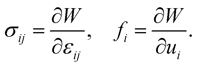 | (4) |
We may apply this framework to a nematic by taking the director n = niei to stand for the displacement field and choosing our energy functional to be the Frank energy. This suggests a choice of strain εij = ∂jni. We may define the stress σ and the force f as in eqn (4). In components, the Frank energy density is
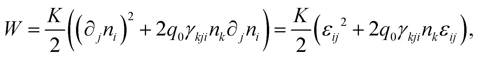 | (5) |
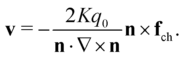
| σ = K(∇n + q0J), fch = Kq0∇ × n, | (6) |
| ∂tn = K(∇2n − 2q0∇ × n). | (7) |
 . We can remedy this by instead considering ε = J∇n. By differentiating the Frank energy density of eqn (5) with respect to this choice of strain, we find that the correct form of the stress is in fact
| σ = K(J∇n − q0(I − nn)), | (8) |
An alternative approach to cholesteric elasticity involves the introduction of a ‘cholesteric derivative’, a connection D which is still compatible with the Euclidean metric but has torsion. This connection is defined by,
| (Din)j = ∇inj + q0γijknk, | (9) |
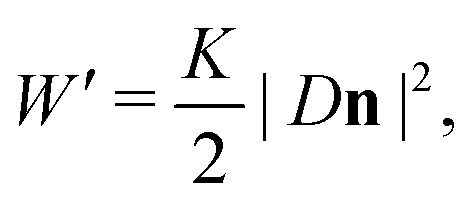 | (10) |
The energy density W′ differs from the Frank energy density W of eqn (5) by the saddle-splay term. This saddle-splay is a total divergence which does not contribute to the Euler–Lagrange equation in the bulk, but nonetheless plays an important role in the elasticity of cholesterics, especially their defects.26,36,44,45 In terms of this energy density, the strain is ε = JDn, and the associated stress tensor is σ = KJDn —this then yields the same stress tensor as we get from the Frank energy density, eqn (8).
2.3 The Ericksen and Peach–Koehler forces
Computing the Peach–Koehler interaction force between defects in a nematic requires us to know the Burgers vector of the defect. Regardless of whether we are dealing with τ- or χ-lines, liquid crystal defects are analogous to screw dislocations in a crystal. For a defect in a liquid crystal with winding k the Burgers' vector is therefore B = 2πkΩ, where Ω is the ‘rotation vector’, defined so that the director field lies everywhere in the planes orthogonal to Ω along the disclination.5,10,46In a cholesteric, this definition leaves something to be desired. The Burgers vector can distinguish between tight and overtwisted disclinations, as the latter class must have a change in winding, which in turn corresponds to points where Ω is orthogonal to the disclination (such points are usually referred to as ‘twist profiles’,5,10,46 but we may also call them ‘Legendrian points’, after a related concept in contact topology27). However, all tight disclinations have a neighbourhood in which the director can be homotoped so that the rotation vector is Ω = ±t, for t the tangent vector to the line.32 Thus, the Burgers vector does not distinguish between edge-like (τ) and screw-like (χ) disclinations, despite their behaviour being quantitatively different, and nor does it ‘see’ the topological invariant q. The insensitivity of the Burgers vector to helical windings is a known issue.10 It may be possible to develop an alternative approach to the Burgers vector which accurately captures this distinction in a cholesteric. This approach, outlined briefly in our previous work,25 is based on the method of convex surface theory for contact topology27 and conceptually much closer to the Volterra process construction of defects.5 Studying possible generalisations or adaptions of the Burgers vector concept is beyond the scope of this work, and we continue to use the standard definition in the remainder of this article.
If t denotes the tangent vector to the line, then the Peach–Koehler force (per unit length) is10
| fPK = (B·σ) × t. | (11) |
An alternative approach to deriving this force was given by Eshelby.21,42 The stress and strain can be packaged into the Ericksen stress tensor ρ, which has components,
| ρij = (W − p0)δij − εkiσkj, | (12) |
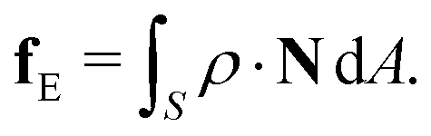 | (13) |
To obtain the force on a disclination line, we must take S to be a tube enclosing the disclination. This approach makes explicit a fundamental assumption that underlies the entire theory: for the force to be well-defined, the integral must be independent of the choice of this surface. This will be the case exactly when ρ is divergence-free, and this in turn occurs only when the director minimises the energy with density W, and so this assumption is necessary for the force to be well-defined. It is well known that the Peach–Koehler theory gives incorrect predictions of disclination line motion when this assumption is not met. For example, if a pair of disclination lines of opposite winding have profiles that are ‘twisted’ relative to one another, not minimising the free energy, then the defects move towards one another on curved trajectories, while the Peach–Koehler theory predicts that they will move along the straight line segment between them.12,47
In an achiral nematic in the one elastic constant approximation this assumption means finding a director field which is harmonic, ∇2n = 0, which is not generally difficult. However, if we wish to generalise the theory to treat chiral materials or materials with distinct elastic constants then finding an energy minimising director analytically is now more of a challenge. This limits practical application of the theory beyond the assumption of ordinary nematics in the one elastic constant approximation. Alternative approaches which do not rely on this assumption (and which also apply to point defects) have been discussed in the literature,12 but these can also become very complicated.
3 Disclination motion in a cholesteric
We now examine interactions between disclination lines in a chiral material through a combination of the Peach–Koehler theory and simulation. The simplest nontrivial case for us to study consists of a pair of straight, parallel disclination strands along lines L1, L2 with winding numbers k1, k2, respectively. It can be shown that a director field minimising the energy for this configuration in the achiral case (q0 = 0) is n = cosϕex + sinϕey, with ϕ the harmonic function,10,47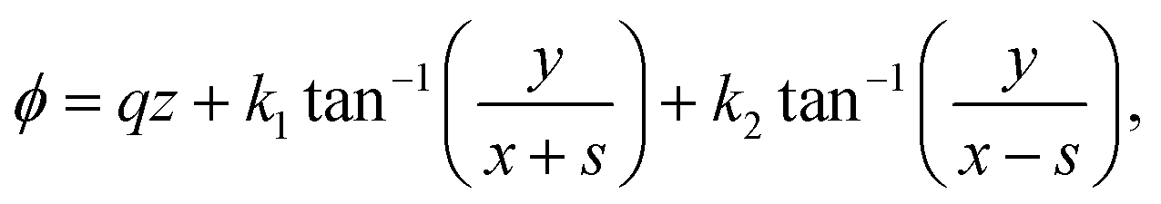 | (14) |
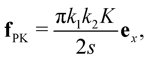 | (15) |
We can use eqn (15) to predict the time at which the defects will annihilate by treating each disclination as a particle with unit mass at position x(t). By Newton's law, the Peach–Koehler force is then equal to the acceleration 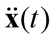 . From this, we may calculate the time for one defect to reach the origin, and since the other defect experiences an equal and opposite force this will be the time to annihilation. As an approximation, this time scales like the separation s.
We now turn to the case of parallel disclination lines in a cholesteric, with q0 > 0. Before we do any analysis, we see what happens in a numerical simulation by minimising the free energy. To simulate disclinations we cannot use the Frank energy of eqn (1), although we will continue to employ this for our analysis. Instead we minimise the Landau–deGennes energy of the Q-tensor Q = n⊗n − I/3 with the initial n being the director with two disclinations of opposite winding ±1/2 separated along the x-axis, exactly eqn (14). The energy to be minimised is then43
 | (16) |
We consider a box of height h = 50 in the z direction and length 2h in the x and y directions. To minimise the potentially-confounding effects of other forces we impose no boundary conditions, making the director periodic along the z direction. For an achiral system, with q0 = 0, the disclinations move closer together along the x-axis regardless of the value of the phase winding q and with a speed that increases as they get closer together (i.e. as the separation 2s gets smaller), exactly as the expression in eqn (15) for the Peach–Koehler force predicts.
To simulate a strongly chiral system we consider q0 = 2π/h so that the box length h is equal to the pitch. We initialise the defects so that the separation between them is also h. Let us first examine the case of a τ-line, q = 0. Instead of moving towards one another and annihilating, the +1/2 disclination always moves along the direction of its ‘tail’ while the −1/2 disclination remains fixed. Thus, depending on the relative orientation they either move apart, Fig. 1(a), or towards one another, Fig. 1(b). We can even rotate the profile by 90 degrees, in which case the +1/2 disclination stills moves along the tail, which is now in a direction orthogonal to the axis between the two disclinations. This shows a curious similarity with the behaviour in an achiral contractile active nematic, where the active forces drive motion of +1/2 defects, but not −1/2 defects, along their tails. In the active system, the broken rotational symmetry of the +1/2 causes it to self-propel in this way, while the −1/2 has a three-fold rotational symmetry that results in a flow field that makes it stable.48 As we shall argue below, similar symmetry considerations apply here. Of course, our system is passive and not active and so the dynamics does not continue indefinitely, and we eventually reach an equilibrium state in which the disclination positions are fixed. Notably, they do not annihilate as they do in the achiral system, even when the relative orientation is such that the motion of the motile defect is towards the other defect, as in Fig. 1(b).
 | ||
| Fig. 1 The motion of τ-lines in a cholesteric depends on the winding and orientation. We consider a pair of disclination lines, one with winding −1/2 (blue) and one with winding +1/2 (red). Lines with winding +1/2 move along the direction of their ‘tail’, and rapidly change their winding to −1/2 via the emission of a +1-winding rotation meron line (green), which has the structure of a double-twist cylinder. The motion of the +1/2-winding line can therefore be either (a) away from, or (b) towards the −1/2-winding line, depending on the relative orientation of the profiles. This is in contrast to the achiral nematic case, where opposite winding disclinations move together and annihilate. We show the initial positions of the lines as transparent tubes, and the final equilibrium positions as solid tubes. In each case we show an inset with the initial director across a surface, coloured according to the angle between the x and y components. The simulations shown are performed when the pitch p is equal to the height of the simulation box. | ||
Another interesting behaviour occurs. In our simulations the +1/2 disclination rapidly converts into a −1/2 disclination via the emission of a +1-winding singular line which immediately ‘escapes into the third dimension' to give a meron tube,25,33 the mechanism for generating double-twist regions that we identified in Section 2. The texture is initially tight, but becomes overtwisted through this process while still maintaining a consistent sense of handedness, n·∇ × n < 0.
Now we simulate a χ-line. We again use the director defined by eqn (14), now with q = 1. We continue to use q0 = 2π/h. The result of our simulation is shown in Fig. 2. In this case we see a destabilisation of the +1/2 defect into a helix due to the motion of the defect along the ‘tail’, whose direction now rotates as we move along the z-axis. As with the τ-line, in this simulation the +1/2 singular line converts into a −1/2 winding singular line, leaving behind a +1 winding meron which sits at the core of the helix—this meron also has a slight helical winding to it, paralleling the disclination, which suggests the motion of the defect occurs slightly before the conversion process. The −1/2 defect also destabilises into a narrow helix, but the width of the helix does not grow as fast as that for the initially +1/2. Similar helical instabilities of +1/2 defect lines are also been observed in simulations of active cholesterics in thin films,49 without the conversion to the −1/2 defect occurring, again due to the self-propulsion effect of the +1/2 defect.
 | ||
| Fig. 2 Initially-straight χ-lines in a cholesteric destabilise into helices. As with τ-lines, defects with winding −1/2 (blue) are stable while those with winding +1/2 convert into winding −1/2 by the emission of a meron line (green), with the local structure of a double-twist cylinder. (a) The helix of the initially +1/2-winding line (right side of image) is wider than that of the initially −1/2-winding line (left side of image). The meron also has a helical shape. The helices are not perfect, but exhibit ‘kinks’, as seen from the side-on view. (b) Running the simulation for longer results in the meron line breaking up into strands that connect parts of the −1/2 disclination. The simulation is shown for pitch p equal to the height of the simulation box h. | ||
As time goes on the director field picks up a large z-component along the disclination that initially has +1/2 winding, but not along the disclination that initially has −1/2 winding. The shape is also not a perfect helix, but rather develops ‘kinks’ that are clearly seen in Fig. 2(a), with the helix becoming more flat in two places and more vertical in the middle. These particular geometric features have been observed in both the τ- and λ-lines of chiral materials in various numerical and experimental settings.39,50–53 They bear a striking resemblance to the ‘cusps’ that appear in Legendrian curves—that is, curves whose tangent vector is everywhere orthogonal to the director—in contact topology.27 On the level of topology the disclinations in cholesterics themselves bear a close correspondence to Legendrian curves, with which they share a topological invariant called the Thurston–Bennequin number.27,28,32 This half-integer is the number of 2π rotations of the director as we go around the disclination line, which defines the helical winding q of a chiral χ-line. It is invariant precisely because there are always Legendrian curves parallel to the disclination in arbitrarily small neighbourhood of the line with Thurston–Bennequin number q, and this cannot be changed by a homotopy preserving chirality.32 The buckling of the χ-line into a helix can then be seen as a buckling instability of the shape of cholesteric layers themselves, which is qualitatively similar to the Helfrich–Hurault instability.28 Eventually, the disclination crosses though the meron tube, resulting in a disclination with meron tethers, Fig. 2(b). The local structure of these crossing points is of type D6+ in the terminology introduced in our previous work.25
The same behaviours observed at p ∼ h can be seen when we simulate a single disclination line in the box, with fixed boundary conditions, and thus the observed behaviour does not arise from interactions between disclination lines. We may suspect that an important role is played by the additional force fch of eqn (6), or rather the related torque n × fch.
We can confirm this by a computation of the Peach–Koehler force. Staring from the same director field as in the achiral case, we may compute its associated stress tensor viaeqn (8) and insert into the formula for the Peach–Koehler force, eqn (11). Clearly, this will yield the same force on L2 as in the achiral material, plus an extra term of the form
| −Kq0(2πk1ez·(I − nn)) × ez. | (17) |
ϕex + sinϕey with ϕ as in eqn (14), this extra term vanishes.
A difficulty here is that our model director field, which is harmonic, is an energy minimiser for an achiral material but not a chiral one. Finding an energy minimiser means solving the Euler–Lagrange equation in eqn (7), which is significantly more difficult than constructing a harmonic director field. Thus, it is quite reasonable that our calculation yields an incorrect prediction. We do not know how to write down a director field that exactly minimises the chiral energy. However, based on theory and a qualitative analysis of numerical simulations the director field
| nτ1/2 = cos(θ/2)m − sin(θ/2)ez, | (18) |
Because both the Burgers’ vector and tangent to L1 are aligned with ez, the only parts of the stress tensor that contribute to the Peach–Koehler force are σzx, σzy. We find that:
 | (19) |
We have described this behaviour at fixed q0, equivalently fixed pitch length, but it is natural to study the crossover between this behaviour and the behaviour of the achiral case q0 = 0, where the disclination lines with opposite winding always come together and annihilate in the centre of the box in accordance with the predictions of the Peach–Koehler theory. To do this we vary the pitch length, so that p = h/a for a ∈ [0.1, 1] (equivalently, q0 = 2πa/h). It is also natural to vary the separation between the defects: we consider 2s = bh, for b ∈ [0.1, 1]. The simulations shown in Fig. 1 and 2 are at a = b = 1.
We consider the same initial condition used for Fig. 1(a). Whether the defects annihilate, or whether the conversion occurs, depends on the values of the parameters, as illustrated in Fig. 3. Generally, even a small chirality is sufficient to produce the observed behaviour provided the defects are sufficiently separated, while a strong chirality can counteract the Peach–Koehler force even at very small initial separations of the lines. The separation line is a hyperboloid where 2s/p is constant.
 | ||
| Fig. 3 The behaviour of a pair of opposite-winding disclination lines in a cholesteric depends on both the distance 2s between them and the pitch length p of the cholesteric. We analyse this in terms of the dimensionless parameters 2s/h and h/p, where h is the height of the simulation box and hence the length of the disclination lines. Red crosses denote parameters for which the disclination lines come together and annihilate, resulting in a uniform texture in equilibrium. This is the parameter regime in which the Peach–Koehler force is sufficiently strong to win out over the effects of chirality. In the other regime, corresponding to green circles, the +1/2 winding disclination changes its winding by meron emission and the system tends to an equilibrium with stable disclinations. | ||
As we can see from Movies S1–S4 (ESI†), the process begins by the +1/2 moving along its ‘tail’, while the initially-planar director rotates into the third dimension close to the +1/2 defect. Once the director rotates by π/2, the meron is emitted. The motion of the +1/2 defect away from the −1/2 defect is a result of chirality, and the strength of any chiral effect must scale linearly with q0. As a rough approximation, obtained by treating s as a constant in the acceleration eqn (11), the time to annihilation scales linearly with s, so that the critical value  of the inverse pitch for which chiral behaviour dominates over the behaviour due to the Peach–Koehler force scales with the separation like
  —equivalently, the critical pitch length scales p* ∼ s—which is qualitatively in agreement with Fig. 3.
It is also interesting to consider defect loops. We consider a closed loop which has vanishing defect charge and is half +1/2-winding and half −1/2-winding, with two Legendrian points (twist profiles). Such a loop can be constructed so that the director field is everywhere 2D, in the xy-planes, and the rotation vector is constant and aligned with the z-direction. Because it is chargeless it can be embedded in a uniform background without additional defects. This texture is shown in Fig. 4(a). In an achiral system, a combination of line tension and the Peach–Koehler force will cause this loop to shrink until it disappears, leaving behind a purely uniform texture. Based on our analysis of straight defects lines, it is reasonable to conjecture that the behaviour will also be different in a chiral system.
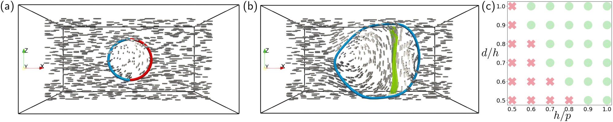 | ||
| Fig. 4 The fate of a chargeless disclination loop in a cholesteric. (a) The director is initially planar, and the loop is comprised of two segments, one +1/2 winding (red) and the other −1/2 winding (blue). In an achiral material in the one elastic constant approximation, this loop would shrink regardless of its diameter as a result of the Peach–Koehler force. Because it has vanishing defect charge it can be removed by this process, resulting in a uniform texture. (b) In a cholesteric, for a sufficiently large loop and sufficiently strong chirality (here the pitch length is p = 0.75h, with the loop being of radius 0.5h, for h the height of the simulation box) this is not what occurs. Instead, the +1/2 segment of the disclination emits a meron to change its winding, and the resulting loop is stabilised despite its vanishing defect charge. (c) As with straight line segments the observed behaviour depends on the initial diameter d of the loop and the chirality, which we characterise through the dimensionless parameters d/h and h/p. Red crosses denote a parameter value at which the loop shrinks and disappears, while green circles denote an equilibrium structure with a stable disclination loop as in (b). | ||
If this texture were chiral, the disclination loop would be an example of the overtwisted class. However, the texture is not chiral and cannot be made chiral by a small perturbation. Instead, in a system with sufficiently strong chirality the local structure of the loop reconfigures itself in much the same way as the straight lines we have just described: the +1/2-winding part of the loop initially moves away along the ‘tail’ of the +1/2 profile, and then changes its winding by the emission of a meron line. Once this has happened, it is possible for the texture to become uniformly chiral, and the resulting disclination line is a tight χ-line (although the texture itself is overtwisted, because of the meron), and the −1/2 profile rotates through two full turns as we move around the loop, so that it has ‘self-linking’.25,54 The topological nature of this process and the local reconfigurations to the director by which it occurs is described in ref. 25.
We simulate this conversion, for an isolated defect loop in a cholesteric. We show the resulting stable structure in Fig. 4(b), and a full simulation in Movie S5 (ESI†). The simulation is in a box of size 2h × 2h × h with periodic boundary conditions, and q0 is chosen so that the pitch length is p = 0.75h, i.e., we take q0 = 2πa/h with a = 0.75. For the simulation shown in Fig. 4 the initial loop is a circle in the xz-plane with diameter d = 0.5h. Loops that are too small still shrink, and loops will also shrink if the material is insufficiently chiral—as with the straight disclination lines, we can determine the stability diagram numerically by performing simulations at different degrees of chirality (characterised by a = h/p) and initial loop diameter (characterised by b = d/h), Fig. 4(c). These structures have been observed previously in simulations55,56 and are structurally similar to both meron lattices and to the blue phases.26
We may also examine the behaviour of disclination lines in a more general setting. Simulating a quench, in which a material is rapidly cooled from the isotropic phase into the cholesteric phase, can be done by initialising the Q-tensor to be fully random inside a box. We impose planar anchoring on the top and bottom slices of the box, with a fixed director field ex along the bottom and top slices. The material then nucleates a complex network of disclination lines, with no preference for a particular winding of the profile and no consistent sense of handedness. This complex network gradually coarsens away as the material minimises the energy in eqn (16). At sufficiently high chirality we observe similar behaviour to what is shown in Fig. 1 and 2. Defects with +1/2 winding are rare, and the material prefers to convert them into −1/2 winding by the emission of meron lines. Over time, and depending on parameters such the dimensions of the simulation box and the strength of the chirality, these disordered networks of disclinations and merons tend towards various more symmetric structures. For example, we may find lattices of −1/2 χ-type disclinations with helical structure, connected by meron tubes (in a manner similar to what is shown in Fig. 2(b)) that are required to meet topological constraints on the projection of the director into cross-sections, or lattices of disclination loops similar to what is shown in Fig. 4(b). In Movie S6 (ESI†) we show an example of a quench resulting in such a loop, in a simulation box of size 2h × 2h × h and a material with pitch length p = 0.75h. In is not our goal to describe these in detail here, as they have been thoroughly explored in previous work53,55,57—our focus is on the process by which we arrive at such structures.
Plainly, our observed behaviour—+1/2 disclinations changing their winding via meron emission, rather than annihilating with −1/2 disclination lines—occurs quite generally, and also cannot be explained by the Peach–Koehler theory alone. In the next section we analyse this behaviour using an alternative approach.
4 The gray stability theorem and the velocity of a cholesteric defect
We now give an analysis of the motion of cholesteric disclinations using a result from contact topology which allows us to directly calculate the velocity field in a chiral material, and also to do this globally and not just along defect lines.4.1 Evolution of chiral director fields without defects
Both fluids and elastic solids evolve by isotopy. This means the configuration of the material at time t is related to its configuration at time 0 by some time-parametrised diffeomorphism ψt, such that ψ0 is the identity. Intuitively, we think of the actual molecules of the solid being moved to different places: the molecule initially at some position p moves to the position ψt(p) at time t. The time derivative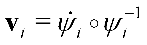 of this diffeomorphism gives the velocity of the material—in fluid dynamics, the diffeomorphism ψt is called the Lagrangian flow, while vt is the Eulerian flow.
A liquid crystal behaves differently. In a passive nematic, the material ‘sticks’ may rotate independently from the background space, inducing distortions without the actual ‘molecules’ of the material moving from their initial positions, and hence the material evolution is via the weaker notion of homotopy. In a homotopy, we may imagine that each ‘stick’ is pinned in place but may rotate freely, as opposed to an isotopy where the sticks may move but not rotate. Changes in the homotopy class of a director require the creation of defects; changes in the isotopy class require the creation of solitons, e.g. merons.25 Homotopy results in more complicated dynamics in general, however, the special topology of the cholesteric simplifies matters considerably. As long as the material is defect free and the constraint n·∇ × n ≠ 0 on the twist holds then, for any homotopy of the director that preserves this constraint, we can always find an isotopy that describes the same motion as the homotopy—that is, we can always think of the evolution of the director as being the result of the background molecules moving without any independent rotation, even if this is not physically what is occurring. This result, know as the Gray stability theorem in contact topology,27,28,35 strongly constrains the motion of a chiral material. Furthermore, the theorem gives an explicit construction of the velocity field of the isotopy, as we now explain.
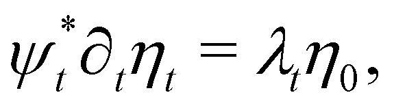
For a nematic, an evolution via isotopy implies that there is a time-dependent diffeomorphism ψt relating the director at time t, nt, to the initial director n0. This relationship is 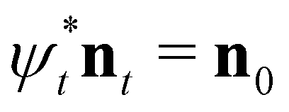 . The dual 1-form ηt to the director field then satisfies the equation
 | (20) |
| ∂tη + Lvη = (∂tlogλ)η, | (21) |
 | (22) |
 , and hence its direction is unambiguous. As noted by Machon,28 this evolution also arises from an appropriate limit of the Ericksen–Leslie equations, and so can be viewed as a kind of simplified hydrodynamics for a chiral director. It implies the conservation of the cholesteric layer structure, and can be used to explain the Helfrich–Hurault buckling instability in cholesterics.28
We should be careful to note that, while the flow field v can be defined for any cholesteric director, in general it will not correspond to the physical flow field. In particular, there is no density in our model for the liquid crystal, so it does not makes sense to impose an incompressibility constraint ∇·v = 0, nor is it required as v is nonphysical. The divergence of the flow field does have meaning however. Consider a volume C which is part of the material, with boundary ∂C. If the flow field v points outwards from the boundary—i.e. the divergence is positive there, ∇·v > 0—then the volume C is growing. Analogously, regions in which ∇·v < 0 are shrinking. If C represents a soliton, e.g. C is a double-twist cylinder in which the director rotates by π/2 in every direction outwards from the core line until it is planar on ∂C, then the condition ∇·v > 0 throughout C implies the volume of the material taken up by the soliton is increasing.
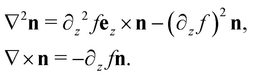
The flow field in eqn (22) is valid for any evolution ∂tn, provided that the twist is nonvanishing at all times and no defects are present. Under dynamics corresponding to energy minimisation we know that the time evolution of a cholesteric director is given by the Euler–Lagrange equation in eqn (7). Putting eqn (7) into eqn (22) then results in an exact global expression for the velocity v of the material's flow field:
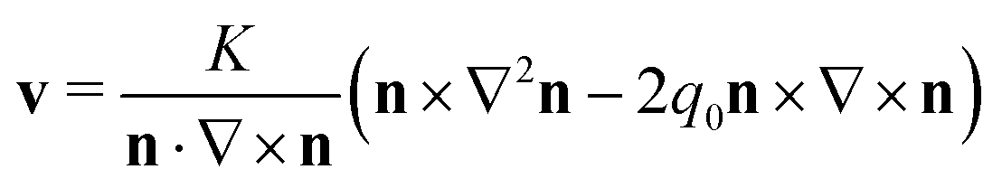 | (23) |
| ∇ × n = (n·∇ × n)n + n × b, | (24) |
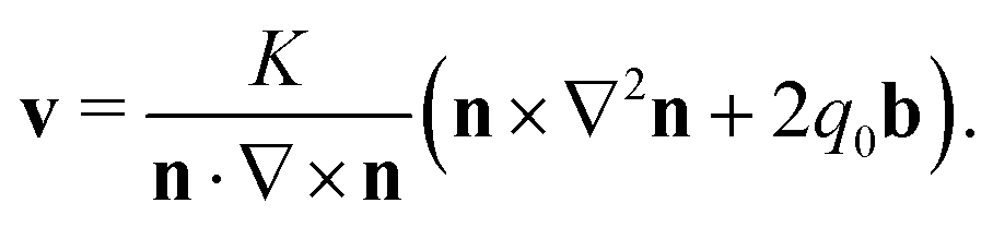 | (25) |
 | (26) |
We can gain further insight into the behaviour of this flow field by examining a simple model. Consider the director field
| n = cosf(z)ex + sinf(z)ey, | (27) |
 | (28) |
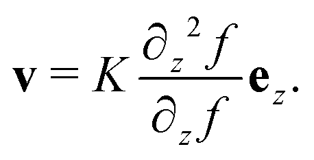 | (29) |
We further illustrate the Gray stability theorem in Fig. 5, which shows the flow field in a meron tube. The expansion of the meron core region is effected by a homotopy of the director field which rotates the ‘sticks’, but by Gray stability this can be seen as the result of an isotopy which ‘moves’ the helical integral curves of the director outwards.
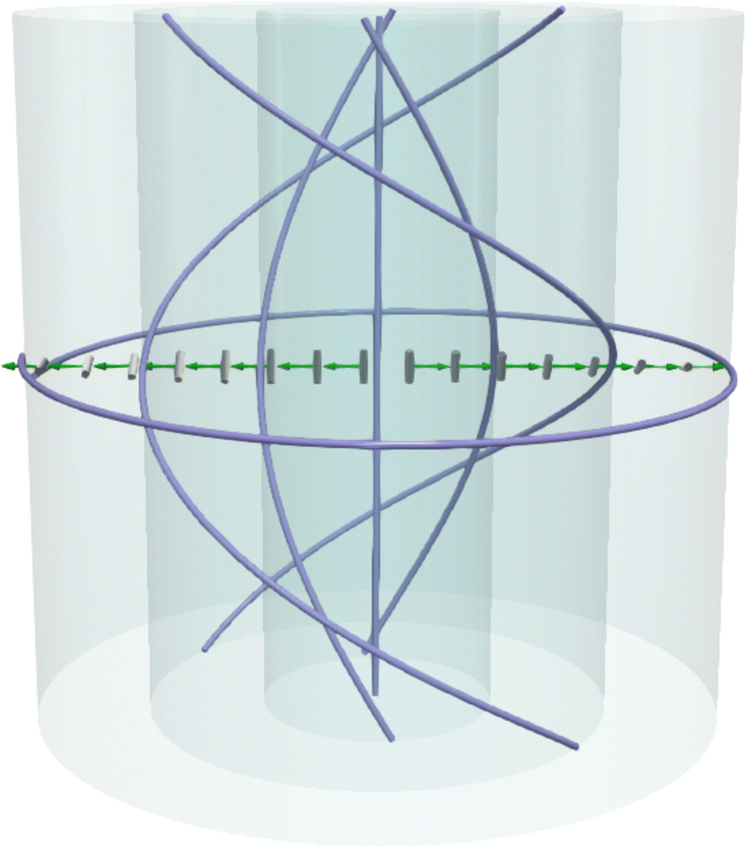 | ||
| Fig. 5 Illustration of the Gray stability theorem for a meron in the form of a double-twist cylinder. Gray stability shows an equivalence between homotopies of the director field and isotopies, which can be viewed as moving the integral curves of the director field. In a meron, the integral curves of the director (purple curves) are helices that limit on a flat circles at the boundary of the meron and a straight line at its core. Energy minimisation leads to an expansion of the meron. This involves a homotopy of the director field (gray), but Gray stability shows the result of this homotopy is the same as the flow of a diffeomorphism that translates the helices outwards along the velocity field in eqn (23), shown in green. Equivalently, we think of the cylinders on which these integral curves sit (blue) also being translated outwards, leading to the growth of the domains which they bound. | ||
4.2 The flow field in the presence of defects
The construction outlined in the previous subsection assumes that no defects are present. If there are point or line defects in the material, then the construction remains valid provided that the defects themselves only move by isotopy and do not undergo structural changes, such as a change in winding number. In general, an evolution that is a homotopy but not an isotopy is associated with one of the following structural changes to a material: (a) the creation or annihilation of defects (b) a change in the structure of the defect set, for example a change in winding of a disclination line or the conversion of a point defect from a radial hedgehog to a hyperbolic hedgehog,25 or else (c) the creation, annihilation, or topological reconfiguration of surfaces on which the twist vanishes.We can still use this theory to predict the motion of a defect line, computing the velocity field at any time except the instant in which structural changes (e.g., meron emission) occur. An advantage of this approach is that it does not just give us the motion of disclination lines but also point defects, as we discuss in Section 5 below. We can also use it to track the motion of other topological/geometric structures associated with the cholesteric, such as merons, Legendrian curves, and the cholesteric layers.28
It is important to note that the velocity field v of eqn (23) will not generally be the velocity of the defects themselves. Rather, it describes the motion of the director field ‘sticks’ via the relationship  , and we may infer the motion of defects from this.
We restrict ourselves to tight disclinations with a well-defined winding number along the entire length, and consider the two subclasses of tight disclination—the τ- and χ-lines—separately. The χ-lines are the most straightforward. We consider the model director,32
| nχ = cos(kθ + qz)ex + sin(kθ + qz)ey | (30) |
| ∇ × nχ = sin(qz + (k − 1)θ)ez − qn. | (31) |
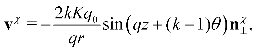 | (32) |
 and we have introduced nχ⊥ = ez × nχ.
These flow fields are shown in Fig. 6(a) and (b), on the cross-section z = 0—for different values of z the picture is rotated as appropriate. In both cases, the velocity is not defined at the defect point itself.
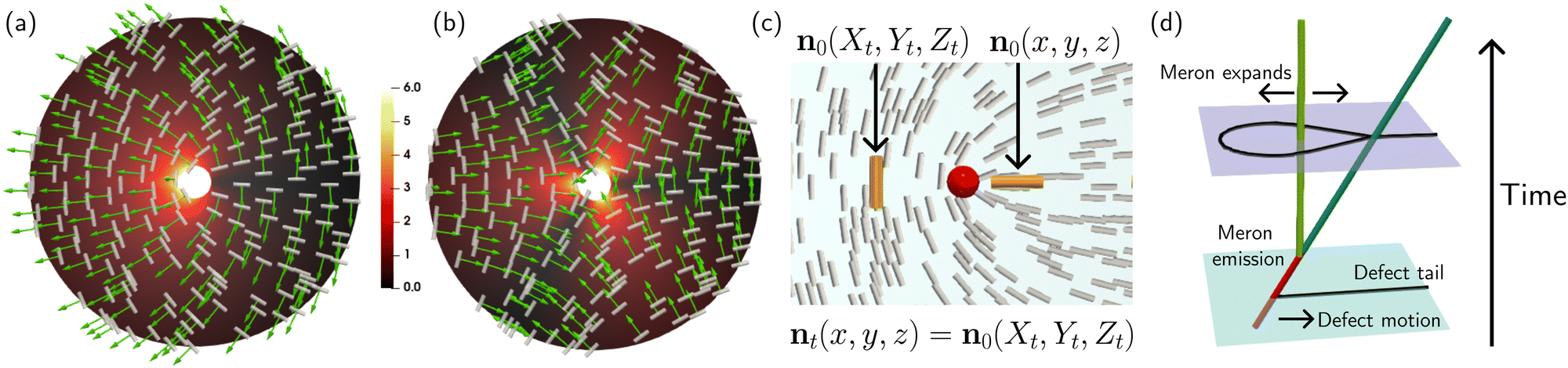 | ||
| Fig. 6 (a) The material flow field generated by the director distortions around a χ-line with winding +1/2. We show the flow field v (green) on the slice z = 0 coloured by the magnitude |v|, along with the director n (grey sticks). The flow depends on z only through the orthogonal direction n⊥ to the director. (b) The flow field around a χ-line with winding −1/2. We can see visually that the symmetries of this flow field will not cause the defect to change its winding. (c) The action of the flow around a +1/2 defect (red sphere) causes instantaneous translation of the coordinate system to the left, which induces a translation of the defect to the right. Consider a point (x, y, z) in the material. At time t, the flow field has moved this to the point (Xt, Yt, Zt). The time t director field nt at (x, y, z) is related to the initial director field n0 by nt(x, y, z) = n0(Xt, Yt, Zt). (d) In the longer term, energy minimisation causes a +1/2 defect to convert into a −1/2 defect through the emission of a meron. We visualise this by examining the spatio-temporal change across a 2D slice in the material, with the third dimension in this panel corresponding to time. Initially—at a time corresponding to the pale blue slice—we see a +1/2 defect (red), which we visualise with the ‘tail’ pointing right. It is moving along this direction due to the flow field, as shown in (c). As time goes on, the disclination undergoes the emission of a meron (green) and changes its winding to −1/2 (blue). The resulting −1/2 defect is not motile in isolation, but in this situation it continues to move in the same direction due to the expansion of the meron tube, as described in the text and indicated on the lilac slice. | ||
First consider the +1/2 disclination, Fig. 6(a). Being aligned with n⊥, we see that the flow field vanishes at the defect point as well as along the ‘tail’ of the defect (positive x-axis), while simultaneously driving the director ‘sticks’ away from the tail. To understand how the defect moves, we calculate the change in coordinates described by these flow fields. Write X, Y, Z = ψχt(x, y, z) for the coordinates of the image of the point initially at physical coordinates (x, y, z) under the action of the isotopy ψχt generated by the flow field in eqn (32). Examining just the X coordinate, and restricting to the slice z = 0, we find
 | (33) |
 and Θ = tan−1(Y/X) are the polar coordinates in the transformed coordinate system. Along the x-axis, we see that Ẋ is negative along the negative x-axis and vanishes along the positive x-axis. If we flow the director field along this isotopy, we have nχt(x, y, z) = nχ0(X, Y, Z). Since the origin is moving left (along the negative x-axis) under the flow, the defect point at the origin moves right (along the positive x-axis) under the flow, i.e. the defect moves along its tail. This is illustrated in Fig. 6(c).
We should be careful to note that this is not exactly the flow under which the defect moves, because the flow field itself will change in time as a result of the director changing, but this calculation predicts its instantaneous motion. This is the behaviour that can be seen in Movies S1–S4 (ESI†), where the +1/2 disclination moves even prior to its conversion to −1/2 winding. This is also agrees with our estimate regarding the critical value of chirality necessary to see this behaviour rather than defect annihilation: the speed at which the +1/2 defect moves towards the −1/2 defect under the Peach–Koehler force is roughly proportional to K/d, with d being the distance between them, while the speed at which it moves away due to the chirality is proportional to Kq0.
The shape of flow field, which drags matter away from the ‘tail’ of +1/2 defect, eventually results in an ‘opening up’ of the comet shape which causes the meron emission. Moreover, we can see from eqn (31) that the force due to chirality fch has a component along the ez direction which causes the ‘escape’ of this singularity, making it the core of a meron—this rotation of the director into the third dimension is also seen in the simulations. As shall shall show momentarily, the flow field around a meron causes it to expand, and this expansion drives the motion of the disclination along the negative x-axis, i.e., the direction that was the tail of the +1/2 defect.
This process is visualised schematically in Fig. 6(d). We consider the defect profile on a single slice, the z = 0 slice, and visualise the change in this profile over time (the third dimension in Fig. 6(d)). We indicate the time 0 behaviour as a pale blue slice. Here, we see a single +1/2 defect (red). As time goes on, the flow field drives a transition into a pair consisting of a meron (double-twist cylinder, green) and a −1/2 defect (blue). In the terminology of our previous work25 this is a D−5 (‘parabolic umbilic’) structural change in the defect set, which can also be observed in experiments.41 The ‘dividing curve’,25,32 the line across which the director is tangent to the z = 0 slice, is shown in black in Fig. 6(d) at these two times. On the lilac slice, the black loop encloses the double-twist region, and the −1/2 defect is pinned to the boundary of this region.
For a χ-line the profile, and hence the direction of the ‘tail’, rotates along the line, and hence we do indeed see the predicted destabilisation of an initially straight line into a helix. The handedness of the helix matches the handedness of the material—indeed, it changes handedness if we simultaneously change the sign of q0 and q.
By contrast, the flow pattern around the −1/2 defect, Fig. 6(c), does not lead to meron emission or to motion. The flows drive the ‘sticks’ inwards, towards the three ‘arms’ of the −1/2 defect and the defect point itself, stabilising the structure. As we have remarked, the behaviour we observe is fundamentally due to the symmetry breaking of the +1/2 defect, the same reason as in an active nematic, albeit by a different mechanism.
To summarise, the effective flow field generated by a +1/2 defect in a cholesteric causes it to spontaneously move along its tail, while −1/2 defects are fixed. Changes in the director structure cause it to change its winding to −1/2. This arrests its motion, however it requires the emission of a meron line (double-twist cylinder) whose own flow field further drives motion. We now compute the flow field in a double-twist cylinder to show this. The director field in a double-twist cylinder of radius R is
 | (34) |
We compute the curl,
 | (35) |
 | (36) |
 | (37) |
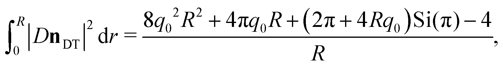
 . By taking the derivative with respect to R and setting this equal to zero, we find this is minimised when,
| 8q02R2 = 2πSi(π) + π2 − 4. | (38) |
From this energetic argument we might naively imagine that a standard cholesteric helix will spontaneously nucleate merons. However, contact topology shows that a conversion from a tight cholesteric helix to an overtwisted state containing a double-twist cylinder requires either (i) the creation of defects, or (ii) the nucleation of regions of reversed handedness. Moreover, since merons are themselves topological objects they can only be created in pairs, so the creation of double-twist cylinders also necessitates the nucleation of −1-winding merons in addition to regions of reversed handedness. This would also be required by a −1/2-winding disclination changing its winding to +1/2.
A local model for a chiral −1-winding meron close to its core axis is
| n−1 = sin(β)(cosθex + sinθey) − cos(β)ez, | (39) |
 . Calculating |Dn−1|2 and restricting to r = 0 gives the energy density along the central line,
| |Dn−1|2|r=0 = 2q02, | (40) |
The emission of a Néel meron (with a radial profile) from a +1/2 defect will also convert it to −1/2, but—in contrast to the double-twist cylinder—a Néel meron will be emitted from the ‘tail’ of the +1/2 comet shape and cause the defect to propel along the direction that was the ‘head’. We do not expect to observe this process in a cholesteric because Néel merons have higher energy than double-twist cylinders. However, we suggest that materials that have an energetic preference for splay distortions could exhibit similar phenomena to those described here for cholesterics, with +1/2 disclination lines changing their winding to −1/2 by the emission of Néel, rather than Bloch, merons. This may potentially result in the stabilisation of chargeless defect loops similar to what is shown in Fig. 4(b).
For completeness we examine the τ-lines as well. These can be described by the director field
| nτ = cosϕm + sinϕez, | (41) |
Thus, it seems that this process of +1/2 defect lines changing their winding may be generic, and that it is the fundamental mechanism underlying the nucleation of double-twist regions within a cholesteric. Moreover, the Peach–Koehler theory cannot account for these changes.
5 The motion of point defects
It is also interesting to apply this framework to the study of point defects in cholesterics. We consider a particular case of relevance to recent experiments: the behaviour of a radial point defect inside a spherical droplet.29,58 Since this situation involves no disclination lines, without loss of generality we may simulate this by minimising the Frank energy (eqn (1)) rather than the Landau–deGennes energy (eqn (16)). Indeed, for the latter energy point defects are known to blow up into small rings, which is undesirable here.We consider a spherical droplet of radius R with normal anchoring boundary conditions. For an achiral system, the energy minimiser is a radial point defect at the centre of the droplet. Using arguments from contact topology, one can show that it is impossible for a director n containing a radial hedgehog point defect to be chiral, i.e. we cannot have n·∇ × n ≠ 0 in a neighbourhood of the defect, and hence hedgehogs always sit on a surface separating regions of reversed handedness.29,33 In experiments and simulations, hedgehogs in a spherical droplet of chiral nematic will displace from the centre of the droplet (their equilibrium position in an achiral nematic) and move towards the boundary in an attempt to minimise the region of disfavoured handedness. We show an example simulation with R/p = 0.5 in Fig. 7(a), where p = 2π/q0 is the pitch length.
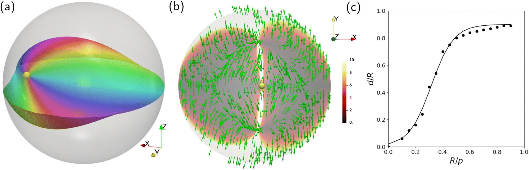 | ||
| Fig. 7 (a) In a cholesteric, a hedgehog point defect initially at the centre of a spherical droplet with radial anchoring will displace from the centre of the droplet. We show the position of the point defect as a yellow orb, and we show a Pontryagin–Thom surface where the z component of the director vanishes, coloured according to the angle between the x and y components. (b) This behaviour can be deduced from the projection into the z = 0 surface of the flow field v (green), which predicts a flow of material away from the negative x-axis of the droplet, resulting in a motion of the point defect along the positive x-axis. The surface z = 0, is coloured according to |v|. (c) At a relatively low chirality (panel (a) shows p = 0.5R) this results in a equilibrium position of the defect that sits some distance d > 0 away from the centre of the droplet. We plot the relative displacement distance d/R is a function of the ratio R/p between the radius of the droplet and the pitch length (black points), which we fit to a sigmoid function, eqn (45) (solid black line). As the cholesteric pitch length grows the defect moves closer and closer to the boundary to minimise the size of the region of ‘wrong’ handedness attached to it. For R/p ≥ 1 the hedgehog reconfigures into a hyperbolic defect and moves back towards the centre of the droplet, as discussed in previous work29 (not illustrated). | ||
We can analyse this using the framework described in the previous section. The nematic hedgehog has n = er in a spherical coordinate system r, θ, ϕ. Since the twist vanishes everywhere we cannot apply the framework described in the previous section to this director, so we instead consider a ‘twisted hedgehog’ of the form,
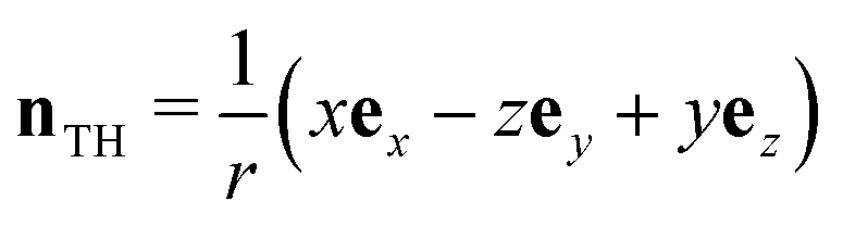 | (42) |
While the twist vanishes along x = 0 it is still possible for us to calculate the flow field within each half of the sphere that the twist is nonzero. We compute that ∇2nTH ∼ nTH, so again only the curl term will contribute to the flow field. We compute that
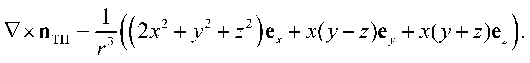 | (43) |
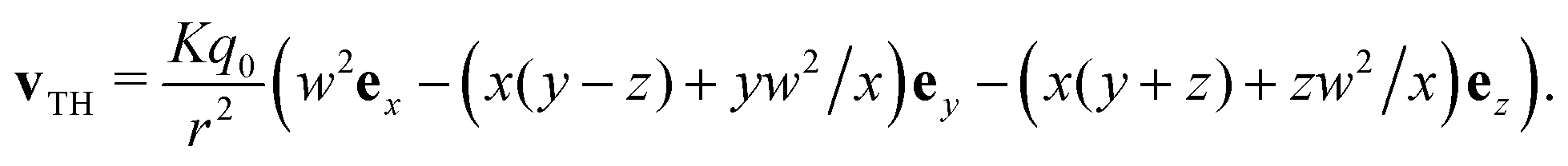 | (44) |
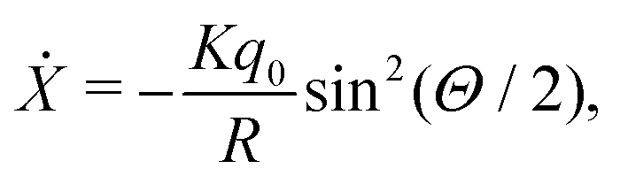
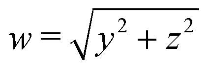 . Close to the surface where x = 0 we have w ≈ r, and the ex-component of the velocity field (which, we observe, is well-defined at x = 0 even if the ey, ez components are not) is approximately +Kq0ex. Thus, this surface should flow along the positive x-axis, and correspondingly the defect will also move away from the centre of the droplet along the positive x-axis with a speed proportional to q0. This matches with the results of our numerical simulations.
This calculation does not include the effects of a hard boundary condition, which is present in the experiments reported in ref. 29 and 58 as well as the simulation shown in Fig. 7(a). This could be included as an additional force by introducing a term proportional to (1 − n·er)2 into the energy, which penalises deviation from the radial anchoring boundary condition. We calculate the flow field numerically for such a texture, with the point defect displaced slightly along the positive x-axis, Fig. 7(b). As our calculation suggests, the flow field drives a motion of the defect along the positive x-axis. The Pontryagin–Thom surface with nz = 0 develops a characteristic ‘clamshell’ shape, seen in Fig. 7(a). This too can be predicted from the flow field, which drives material ‘up’ away from the z = 0 plane on one side of the droplet, and ‘down’ on the other.
This describes the instantaneous motion of the defect, but not its long term behaviour. The boundary repulsion effect results in an equilibrium position for the defect which is dependent on the inverse pitch length q0. By performing simulations starting from the initial condition in eqn (42) with the defect displaced slightly from the origin,§ we determine the equilibrium normalised displacement d/R of the hedgehog from the centre of the droplet as a function of the ratio R/p, for fixed K = 0.1 and a hard boundary condition, corresponding to an effectively infinite anchoring energy.¶ The numerically-calculated values are shown as circles in Fig. 7(c). Based on the shape of the simulation data, we attempt to fit the displacement d/R against a sigmoid function,
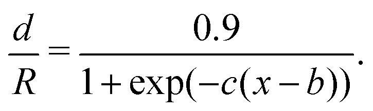 | (45) |
At large enough chirality, p ∼ R, the hedgehog initially displaces towards the boundary, but then eventually moves back towards the centre of the droplet as it transforms from a radial to a hyperbolic structure which can be locally chiral.29 Various aspects of this process have been described previously using analytics and simulations.25,29,59,60 In Movie S7 (ESI†), we show a full simulation of the conversion process at p = R from various angles.
6 Discussion
The energetic preference for maintaining a uniform sense of handedness imposes strong constraints on the textures formed in a chiral material, and in particular the structure of the defects.23,29,32,33 It also imposes strong constraints on dynamics,28 a fact we have exploited here to study the kinematics of defects in a passive cholesteric liquid crystal. We have shown via a combination of simulations and analytical calculations that the τ- and χ-line disclinations of a cholesteric exhibit qualitatively different dynamical behaviour from one another and also from the achiral nematic case. Notably, defects of opposite winding do not attract as they do in an achiral material, but rather +1/2 defects change their winding to −1/2 by emission of a meron, and the resulting disclination propels along the ‘tail’ of the original +1/2 ‘comet’. This latter behaviour results in initially-straight χ-lines destabilising into helices. Following Machon,28 we have performed an analysis of disclination motion in cholesterics using the Gray stability theorem from contact topology to calculate the material velocity field, which we have used to explain this phenomenon: the asymmetry of +1/2 defects drives an ‘unfolding’ of the comet shape, resulting in change in winding and corresponding meron emission.We have argued that the Peach–Koehler force does not explain this behaviour, as the additional terms that arise from chirality do not result in different predictions of the motion of the disclination lines. It is not clear to us whether this can be remedied, either by the consideration of additional forces, or perhaps a modification to the definition of the Burgers vector along the lines suggested in our previous work.25 The Peach–Koehler framework can still correctly predict the behaviour in some cases, for instance in the experiments described in ref. 39. As we have shown, the Peach–Koehler force still dominates the interactions when the chirality is small and/or the separation between the disclinations is small. However, in general we believe that the notion of meron-mediated interactions between disclination lines25 challenges the extent to which the Peach–Koehler formalism can describe the full behaviour of nematic liquid crystals.
It is well known that the Peach–Koehler force in both a crystal and a liquid crystal is analogous to the Lorentz force in electromagnetism.20,43 Our work therefore hints at the potential for further analogies between liquid crystals and well-studied phenomena in field theory and particle physics. We have described an interaction between disclinations which is mediated by merons and cannot be explained by the Peach–Koehler force—this sounds tantalisingly similar to the weak interaction between fermions, which does not arise from electromagnetism and is mediated by bosons. Textures such as meron and Skyrmion lattices also have their analogues in particle physics. It is natural to ask whether this qualitative comparison may be made formal, and whether this may facilitate a deeper understanding of the phenomena we have described in this work. It may be possible to derive such a correspondence by considering field theories of liquid crystals. For example, the free energy of a uniaxial liquid crystal can be written as an SO(2) gauge theory with an interaction term involving the Peach–Koehler force, at least when the material is achiral.61 Further, an analogy can be made between smectics/cholesterics and the Ginzburg–Landau theory of superconductors, and this analogy has been used to understand the twist-grain boundary phase.62
We have also applied our analysis based on the Gray stability theorem to a hedgehog point defect in a spherical droplet, a scenario where the assumption that the director is everywhere chiral does not hold. Even without this assumption, the calculation of the flow field from Gray stability is still possible, and it still sheds insight on the behaviour of the defect, which drifts away from the centre of the droplet and towards the boundary.29,58 Our calculations are based on the energy (eqn (1)), which is also the energy of a chiral ferromagnet with the Dzyaloshinskii–Moriya interaction. Our results can therefore be applied to understand the motion of merons, Skyrmions, and point defects (Bloch points) in these materials as well.
The example of the hedgehog defect suggests that an analysis using the Gray stability theorem could potentially be extended far beyond its original application to defect-free chiral structures by relaxing the requirement that the twist be nonzero. More generally, the distinction between motion of a nematic which is a homotopy that integrates to an isotopy and a motion which is merely a homotopy is both subtle and interesting,25 with structural and dynamical consequences that are not well understood. Violation of the integrability condition occurs due to the creation/annihilation of topologically-protected features (defects, solitons) and potentially also due to the creation/annihilation of non-topological features such as twist, splay, and bend walls. While bend and splay walls are frequently discussed in the context of active nematics due to their relationship with the active force, especially in two-dimensional systems, to our knowledge the dynamics of twist walls have not been examined in any detail, nor have two-dimensional bend and splay walls been analysed in detail in three-dimensional systems. The Gray stability theorem may help to study the motion of these geometric features in both passive and active materials, and we welcome further work in the area.
Conflicts of interest
There are no conflicts to declare.Appendices
A Numerical simulations
In this appendix we give further details of the numerical simulations performed in this work.All simulations involve numerical minimisation of the Landau–deGennes free energy given by eqn (16), except for the simulations shown in Fig. 7 and Movie S7 (ESI†), where we use the Frank energy, eqn (1). For the bulk part of the Landau–deGennes energy we take parameters A = −a0β(1/β − 1/3), B = −a0β, C = a0β with a0 = 0.05 and β = 0.6 in all simulations. We take the elastic constant K = 0.05 for the distortion part of the Landau–deGennes energy, as well as the Frank energy, and explore different values of the chirality q0 as detailed in the main text. We did explore simulations in which the elastic constants differ slightly, but the results were qualitatively the same as for the one constant energy.
We numerically minimise the energy using a finite-difference scheme on a cubic grid with Lx × Ly × Lz grid points. For the simulations shown in Fig. 1–4 and Movies S1–S6 (ESI†) we take Lx = Ly = 100, Lz = 50. For the simulation shown in Fig. 7 and Movie S7 (ESI†) we take Lx = Ly = Lz = 100.
For the simulations in Fig. 1–4 and Movies S1–S4 (ESI†) we impose periodic boundaries along the z direction and free boundaries (unconstrained evolution) along the x and y directions. Imposing periodic boundaries or fixed boundaries along the x and y directions does not change the results. In Fig. 7 and Movie S7 (ESI†) we impose a hard radial boundary on the director within the spherical droplet by constraining it to be radial for all grid points outside a fixed radius of R = 48 grid points from the centre—this corresponds to an anchoring energy with an effectively-infinite elastic constant.
We track the change in energy from timestep to timestep throughout the simulations, and deem the director to have reach an equilibrium when the change falls below a threshold value.
The director is extracted from the Q-tensor Q by finding the unit eigendirection corresponding to the largest eigenvalue. Disclination lines are points where Q vanishes. We identify them using a suitable contour of the function |Q|. Our choice of a0 for the parameter in the bulk part of the energy sets are desired value of |Q| ∼ 0.4 throughout the bulk, with large deviations from this value only occurring close to defects. We find values of |Q| = 0.2 to |Q| = 0.25 to be appropriate for identifying disclinations. The winding of the disclination is determined by plotting the ‘dividing curve’ on this contour, the set of points where the director is tangent to the surface. This allows for a visual identification of winding numbers, as described in ref. 25. We can also identify this winding by plotting the angle between the x and y components of the director field on a surface cutting across the defect. Merons are escaped structures, and be identified by plotting the set of points where the director aligns with the z-direction as described in ref. 25. The point defect in the simulation shown in Fig. 7 and Movie S7 (ESI†) is identified by plotting a Pontryagin–Thom surface and looking at the colour winding.29,63
Data availability
The data supporting this article have been included as part of the ESI.†Acknowledgements
JP and RGM acknowledge funding from the EMBL Australia program. RGM acknowledges funding from the Australian Research Council Centre of Excellence for Mathematical Analysis of Cellular Systems (CE230100001).Notes and references
- M. Kleman, L. Michel and G. Toulouse, J. Phys. Lett., 1977, 38, 195–197 CrossRef CAS.
- M. Kleman, J. Phys. Lett., 1977, 38, 199–202 CrossRef.
- N. D. Mermin, Rev. Mod. Phys., 1979, 51, 591–648 CrossRef CAS.
- G. Volovik and O. Lavrentovich, Zh. Eksp. Teor. Fiz., 1983, 85, 1997 CAS.
- M. Kleman, Points, lines, and walls: in liquid crystals, magnetic systems, and various ordered media, J. Wiley, Chichester, New York, 1983 Search PubMed.
- K. Jänich, Acta Appl. Math., 1987, 8, 65–74 CrossRef.
- M. Kleman, Rep. Prog. Phys., 1989, 52, 555–654 CrossRef CAS.
- M. Kleman and J. Friedel, Rev. Mod. Phys., 2008, 80, 61–115 CrossRef CAS.
- S. Čopar, Phys. Rep., 2014, 538, 1–37 CrossRef.
- C. Long, X. Tang, R. L. B. Selinger and J. V. Selinger, Soft Matter, 2021, 17, 2265–2278 RSC.
- G. P. Alexander and R. D. Kamien, Liq. Cryst. Rev., 2022, 10, 91–97 CrossRef CAS.
- C. D. Schimming and J. Viñals, Proc. R. Soc. A, 2023, 479, 20230042 CrossRef.
- C. Long and J. V. Selinger, Liq. Cryst., 2024, 1–17 Search PubMed.
- J. M. Kosterlitz and D. J. Thouless, J. Phys. C: Solid State Phys., 1973, 6, 1181–1203 CrossRef CAS.
- S. R. Renn and T. C. Lubensky, Phys. Rev. A: At., Mol., Opt. Phys., 1988, 38, 2132–2147 CrossRef PubMed.
- I. Chuang, B. Yurke, A. N. Pargellis and N. Turok, Phys. Rev. E: Stat. Phys., Plasmas, Fluids, Relat. Interdiscip. Top., 1993, 47, 3343–3356 CrossRef CAS PubMed.
- G. Taylor, Proc. R. Soc. A, 1934, 145, 362–387 CAS.
- P. Poulin, H. Stark, T. C. Lubensky and D. A. Weitz, Science, 1997, 275, 1770–1773 CrossRef CAS PubMed.
- M. Škarabot, M. Ravnik, S. Žumer, U. Tkalec, I. Poberaj, D. Babič, N. Osterman and I. Muševič, Phys. Rev. E: Stat. Phys., Plasmas, Fluids, Relat. Interdiscip. Top., 2007, 76, 051406 CrossRef PubMed.
- M. Peach and J. S. Koehler, Phys. Rev., 1950, 80, 436–439 CrossRef.
- J. D. Eshelby, Philos. Mag. A, 1980, 42, 359–367 CrossRef CAS.
- C. Long, M. J. Deutsch, J. Angelo, C. Culbreath, H. Yokoyama, J. V. Selinger and R. L. Selinger, Phys. Rev. X, 2024, 14, 011044 CAS.
- D. A. Beller, T. Machon, S. Čopar, D. M. Sussman, G. P. Alexander, R. D. Kamien and R. A. Mosna, Phys. Rev. X, 2014, 4, 031050 CAS.
- A. Jákli, O. D. Lavrentovich and J. V. Selinger, Rev. Mod. Phys., 2018, 90, 045004 CrossRef.
- J. Pollard and R. G. Morris, Morse Theory and Meron Mediated Interactions Between Disclination Lines in Nematics, arXiv, 2024, preprint, arXiv:2408.01032, https://arxiv.org/abs/2408.01032.
- D. C. Wright and N. D. Mermin, Rev. Mod. Phys., 1989, 61, 385–432 CrossRef CAS.
- H. Geiges, An Introduction to Contact Topology, Cambridge University Press, 1st edn, 2008 Search PubMed.
- T. Machon, New J. Phys., 2017, 19, 113030 CrossRef.
- J. Pollard, G. Posnjak, S. Čopar, I. Muševič and G. P. Alexander, Phys. Rev. X, 2019, 9, 021004 CAS.
- J. Eun, J. Pollard, S.-J. Kim, T. Machon and J. Jeong, Proc. Natl. Acad. Sci. U. S. A., 2021, 118, e2102926118 CrossRef CAS PubMed.
- Y. Han, J. Dalby, A. Majumdar, B. M. G. D. Carter and T. Machon, Phys. Rev. Res., 2022, 4, L032018 CrossRef CAS.
- J. Pollard and G. P. Alexander, Phys. Rev. Lett., 2023, 130, 228102 CrossRef CAS PubMed.
- J. Pollard and G. P. Alexander, New J. Phys., 2024, 26, 063027 CrossRef CAS.
- C. G. Callan, R. Dashen and D. J. Gross, Phys. Rev. D: Part. Fields, 1978, 17, 2717–2763 CrossRef CAS.
- J. W. Gray, Ann. Math., 1959, 69, 421 CrossRef.
- T. Machon and G. P. Alexander, Phys. Rev. X, 2016, 6, 011033 Search PubMed.
- G. E. Volovik and K. Zhang, Phys. Rev. Res., 2020, 2, 023263 CrossRef CAS.
- G. E. Volovik, J. Exp. Theor. Phys., 2020, 131, 11–17 CrossRef CAS.
- I. Smalyukh, S. Shiyanovskii and O. Lavrentovich, Chem. Phys. Lett., 2001, 336, 88–96 CrossRef CAS.
- V. Poenaru and G. Toulouse, J. Phys., 1977, 38, 887–895 CrossRef.
- J.-S. Wu, R. A. Valenzuela, M. J. Bowick and I. I. Smalyukh, Topological Rigidity and Non-Abelian defect junctions in chiral nematic systems with effective biaxial symmetry, arXiv, 2024, preprint, arXiv:2410.19293, https://arxiv.org/abs/2410.19293.
- J. D. Eshelby, J. Elasticity, 1975, 5, 321–335 CrossRef.
- P.-G. deGennes and J. Prost, The physics of liquid crystals, Clarendon Press, Oxford, 2nd edn, 2013 Search PubMed.
- J. P. Sethna, D. C. Wright and N. D. Mermin, Phys. Rev. Lett., 1983, 51, 467–470 CrossRef CAS.
- J. V. Selinger, Liq. Cryst. Rev., 2018, 6, 129–142 CrossRef CAS.
- J. Friedel and P. DeGennes, C. R. Acad. Sci., Paris, Ser. A B, 1969, 268, 257–259 CAS.
- X. Tang and J. V. Selinger, Soft Matter, 2017, 13, 5481–5490 RSC.
- L. Giomi, M. J. Bowick, P. Mishra, R. Sknepnek and M. Cristina Marchetti, Proc. R. Soc. A, 2014, 372, 20130365 Search PubMed.
- W. Wang, H. Ren and R. Zhang, Phys. Rev. Lett., 2024, 132, 038301 CrossRef CAS PubMed.
- J.-S. B. Tai and I. I. Smalyukh, Science, 2019, 365, 1449–1453 CrossRef CAS PubMed.
- J.-S. Wu and I. I. Smalyukh, Liq. Cryst. Rev., 2022, 10, 34–68 CrossRef CAS.
- P. Pieranski, Liq. Cryst. Rev., 2022, 10, 6–33 CrossRef CAS.
- J.-i Fukuda, Liq. Cryst. Rev., 2022, 10, 69–90 CrossRef CAS.
- S. Čopar and S. Žumer, Proc. R. Soc. A, 2013, 469, 20130204 CrossRef.
- J.-I. Fukuda and S. Žumer, Nat. Commun., 2011, 2, 246 CrossRef PubMed.
- J.-i Fukuda and S. Žumer, Progress in Liquid Crystal Science and Technology, World Scientific, 2013, pp. 113–131 Search PubMed.
- J.-i Fukuda and S. Žumer, Phys. Rev. Lett., 2011, 106, 097801 CrossRef PubMed.
- G. Posnjak, S. Čopar and I. Muševič, Nat. Commun., 2017, 8, 14594 CrossRef CAS PubMed.
- S. Paparini and E. G. Virga, Liq. Cryst., 2023, 50, 1498–1516 CrossRef CAS.
- F. Ciuchi, M. P. De Santo, S. Paparini, L. Spina and E. G. Virga, Liq. Cryst., 2024, 1–13 CAS.
- K. Kawasaki and H. R. Brand, Ann. Phys., 1985, 160, 420–440 CAS.
- T. Lubensky, Phys. A, 1995, 220, 99–112 CrossRef.
- B. G.-G. Chen, PhD Thesis, University of Pennsylvania, 2012 Search PubMed.
Footnotes |
| † Electronic supplementary information (ESI) available. See DOI: https://doi.org/10.1039/d4sm01478b |
| ‡ A ‘Néel’ meron, which has the director pointing radially outwards from the core line, can be made chiral only be introducing a rotational component to the director, in which case it is topologically equivalent to the Bloch type and its cross-section still defines an overtwisted disk.33 |
| § This symmetry-breaking is necessary to avoid an unstable equilibrium in the numerics. The direction of displacement does not influence the direction along which the defect moves—the defect will always move so as to minimise the region of positive twist. |
| ¶ For an effectively infinite anchoring strength this distance will not depend on K, however for finite anchoring strength it will depend on the ratio between K and the elastic constant associated with the anchoring term in the free energy. |
| This journal is © The Royal Society of Chemistry 2025 |