
 Open Access Article
 This Open Access Article is licensed under a
 Creative Commons Attribution 3.0 Unported Licence
Shape selective cracking of polypropylene on an H-MFI type zeolite catalyst with recovery of cyclooctane solvent†
Tomohiro
Fukumasa
a,
Yuya
Kawatani
a,
Hiroki
Masuda
a,
Ikuto
Nakashita
a,
Ryusei
Hashiguchi
a,
Masanori
Takemoto
 b,
Satoshi
Suganuma
c,
Etsushi
Tsuji
a,
Toru
Wakaihara
d and
Naonobu
Katada
*a
b,
Satoshi
Suganuma
c,
Etsushi
Tsuji
a,
Toru
Wakaihara
d and
Naonobu
Katada
*a
aCenter for Research on Green Sustainable Chemistry, Faculty of Engineering, Tottori University, 4-101 Koyama-cho Minami, Tottori 680-8552, Japan. E-mail: katada@tottori-u.ac.jp
bDepartment of Chemical System Engineering, School of Engineering, The University of Tokyo, 7-3-1 Hongo, Bunkyo-ku, Tokyo 113-8656, Japan
cInstitute for Catalysis, Hokkaido University, Kita21, Nishi10, Kita-ku, Sapporo, Hokkaido, Japan
dInstitute of Engineering Innovation, School of Engineering, The University of Tokyo. Department of Project, 2-11-16 Yayoi, Bunkyo-ku, Tokyo 113-8656, Japan
First published on 21st November 2024
Abstract
The use of hydrocarbon solvents for zeolite-catalyzed polyolefin cracking narrows the molecular weight distribution of the products, which enhances the efficiency of polyolefin chemical recycling to naphtha, a key precursor to polyolefins. However, solvent consumption remains a challenge. In this study, zeolite microporosity was used to achieve shape-selective polyolefin cracking while allowing solvent recovery. With an H-MFI type zeolite catalyst combined with cyclooctane as the solvent, polypropylene was selectively converted without cyclooctane reactivity. In a typical case, 84% of polypropylene was converted into C3-27 aliphatic and monocyclic aromatic compounds (equivalent to liquid petroleum gas, naphtha, kerosene, jet and diesel) with 79% selectivity, while 95% of cyclooctane was recovered. This study is the first to demonstrate solvent recyclability in polyolefin cracking on an acidic zeolite, contributing to the chemical recycling of polyolefin into its precursor, naphtha, with high selectivity facilitated by the presence of solvent but without solvent consumption.
Sustainability spotlightHere we submit a paper “Shape Selective Cracking of Polypropylene on an H-MFI Type Zeolite Catalyst with Recovery of Cyclooctane Solvent”, reporting a fact that polyolefin was selectively cracked into naphtha-related gaseous and liquid hydrocarbons over an MFI-zeolite catalyst with small micropores, while the solvent, cyclooctane, was mostly recovered. This will open a way for chemical recycling of polyolefins without consuming other materials contributing to sustainability in the plastic industry. The paper states that the reason for this phenomenon was the shape-selectivity due to the microporous structure. The contents are based on the sustainability concept and will gather interest of the readers of RSC Sustainability. |
Introduction
Achieving a carbon-neutral society requires the exploration of alternatives to the two primary uses of petroleum: fuel and chemical resources. While petroleum-based fuels are being rapidly replaced by electricity, hydrogen, ammonia and synthetic fuels—often sourced from solar, wind or biophotosynthetic energy—the demand for petroleum-derived chemicals, especially plastics, remains high. In 2015, it was estimated that 300 million tons of plastic were discarded (landfilled or incinerated), of which approximately 100 million tons were recycled.1 Expanding plastic recycling is critical for establishing a sustainable carbon cycle and protecting the marine environment.Polyolefins (POs), such as polyethylene (PE) and polypropylene (PP), account for 60% of the plastics produced and consumed.1 In actual waste, even after advanced sorting,2 a variety of PO molecules with different chain lengths and microstructures remain. In the field of PO recycling, mechanical recycling is difficult because it involves separating the waste plastic and restoring the initial physicochemical properties of each polymer part. Therefore, chemical recycling is required to convert POs into hydrocarbons equivalent to their raw material, namely, naphtha.3,4
POs can undergo hydrogenolysis into small hydrocarbon molecules. For hydrogenolysis, noble metal catalysts, such as Ru5 or Pt,6 are required to upgrade POs into alkanes under pressurized hydrogen. By contrast, POs are long-chain alkanes. The catalytic cracking of short-chain alkanes has been well studied and practiced since the early 20th century.7–16 The most advanced catalysts for alkane cracking are acid-form (H-form) zeolites with framework types such as FAU and MFI.
Zeolites are a group of crystalline materials formed by a three-dimensional network of Si–O covalent bonds with micropores due to the framework topology. Some of the Si (oxidation number +4) in the framework is substituted by Al (+3), which generates a negative charge on the framework which can hold a cation. When the counter cation is H+, the zeolite is called H-, proton-, acidic- or acid-form zeolite, and the proton plays the role of Brønsted acid. The number of Brønsted acid sites on the H-form zeolite is principally equal to the number of Al atoms.17–19 This enables the adjustment of the concentration of Brønsted acid sites and the distance between two Brønsted acid sites, which strongly influences the catalytic selectivity and life.20 The acid strength (the ability to stabilize the counter cation21) is dependent on the framework topology.19,22 Some specific framework topologies, e.g., MFI, show strong Brønsted acidity owing to the structural feature generating strong compression from both ends of the Si–OH–Al group.21–23
H-form zeolites have been used in various chemical reactions, including conversion of artificial24–37 and bio-derived20,38 polymers. H-form zeolites have high potential for recycling and extended catalyst life, reducing the costs of catalysts because the framework components are only Si, O and Al. These components form strong covalent bonds and exhibit durability against high temperatures, humidity, and reduction/oxidation conditions. Even on zeolites, the Al–O–Si–O–Al bond induces dealumination and structural distortion.18,39,40 However, the Al–O–Si–O–Al bond is not formed with <ca. 1 mol kg−1 of Al in the MFI framework.41 Therefore, an MFI type zeolite with <ca. 1 mol kg−1 of Al (called high silica ZSM-5 zeolite, corresponding to >16 of the Si/Al molar ratio) does not lose crystallinity at temperatures less than approximately 1273 K,42 suggesting structural stability at such a reaction temperature of 673 K and durability against calcination typically at 873 K for regeneration of the active sites. Previous studies have found that this type of zeolite exhibits recyclability as a catalyst for the degradation of polymers such as sucrose and cellulose.20 Zeolites are microporous, which limits the diffusion rates of reactants; however, even with this drawback, the strong Brønsted acidity of these zeolites allows the catalytic cracking of alkanes at ca. 773 K, where product selectivity can be controlled.43 The catalytic cracking of POs has already been attempted.24,26–37,44–52 The mechanism of acid catalysis for PO cracking has been elucidated using metal chloride catalysts,53 which are not practical owing to the difficulty in separating the catalyst from the product. A narrow molecular weight distribution was observed on an MFI type zeolite catalyst.25 Based on the reaction conditions and nature of the catalyst, two types of reactions are possible: (1) combined pyrolysis (non-catalytic thermal decomposition) and catalytic cracking of the pyrolysis product,54,55 and (2) direct cracking of POs over a solid catalyst.56,57
Previous reports have indicated that the use of solvents provides advantages in the catalytic cracking of polymers.54,58–61 In the reaction field, a pure PO forms a highly viscous liquid, causing problems such as local overheating of the reactor wall and overdecomposition into carbonaceous materials. Solvents (or simply co-existing liquids) suppress the viscosity of the reactants and promote thermal and material diffusion.58,60 Because the reaction temperature can be easily controlled in the presence of solvent, the product is expected to have a narrow molecular weight distribution. The use of solvents is also advantageous for the separation and transportation of practical waste prior to the reaction.62
However, methods using solvents for PO cracking have a fatal drawback. The solvent (any organic compound) reacts and is consumed in the same manner as the polymer as long as it is in contact with the active sites, making it impossible to recycle the carbon. In limited cases, attempts have been made to recover the solvent. To recycle carbon fibers from carbon fibre-reinforced polymer (CFRP) composites, the resin matrix was decomposed by cleaving the ester bonds under mild conditions (433 K), and the relatively stable monoethanolamine solvent was recovered.63 Decomposition of polyethylene terephthalate (PET) was achieved under mild conditions (<403 K) while suppressing the decomposition of the imidazole solvent.64 The chemical stability of ionic liquids has been applied for the recovery of solvents during polymer decomposition.65 All of these known techniques combine reaction conditions suitable for the decomposition of the target polymer with a solvent that is stable under those conditions. However, the decomposition of POs (long-chain alkanes), which are chemically inert, requires extreme reaction conditions, such as a high temperature of 673 K.
In this study, we aimed to develop a method based on the shape selectivity owing to the microporosity of zeolites. Because it has been reported that PO cracking proceeds within micropores,37 a combination of a zeolite with small micropores and a solvent with a bulky molecular shape was used to ensure shape selectivity of the reactants for the selective cracking of POs and selective recovery of the solvent (Scheme 1). For the first time, we combined an MFI type zeolite with small micropores (diameter ca. 0.55 nm)66 as a catalyst and cyclooctane with a bulky molecular shape (ca. 0.8 nm)67 as a solvent, which will be the first step in developing a method for the chemical recycling of POs without consuming other materials.
 | ||
| Scheme 1 Assumed material flow during shape selective cracking in micropores of zeolite. | ||
To the best of our knowledge, the effect of micropore characteristics on the polymer cracking activity and product distribution has been reported;56,68–73 however, the selective conversion of polymers and solvent recovery based on the shape selectivity of the reactants have not been reported. Additionally, we tested a series of zeolites treated with a base (alkali) in the presence of amorphous silica for PO cracking. In addition to changes in the external surface area by the base treatment,74 we expected the modification of the local structure, such as recrystallization,75 by the presence of amorphous silica. Based on the change in PO cracking activity caused by the silica alkali treatment, the location of PO cracking and the origin of selectivity were discussed.
Results and discussion
Quality of the parent MFI sample
X-ray diffraction (XRD) showed that the parent sample (denoted as “0” in Fig. 1) had a strong-intensity diffraction pattern attributed to the MFI crystal structure. Nitrogen adsorption at 77 K of the parent sample (denoted as “0” in Fig. S1†) showed a type I isotherm76 and high micropore volume (0.13 cm3 g−1), as shown in Table 1. These indicate that the parent sample had a highly crystalline MFI framework topology.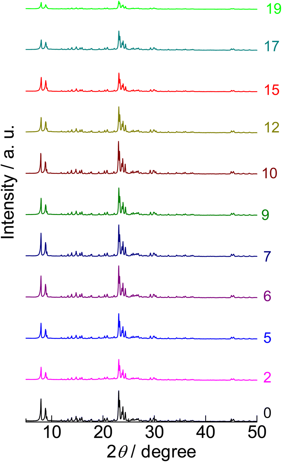 | ||
| Fig. 1 X-ray diffraction patterns of (0) parent MFI and (2)–(19) silica-alkali-treated MFI under Cu Kα X-ray irradiation (0.154 nm). The digits indicate the amount of NaOH used for the silica-alkali treatment in units of mol kgzeolite−1. | ||
| Sample name | Description | Si/Al molar ratio | [Al]/mol kg−1 | Origin | Micropore volumea/cm3 g−1 | External surface areab (area of meso- and macropore wall)/m2 g−1 | Brønsted acid amount/mol kg−1 | Lewis acid amount/mol kg−1 |
|---|---|---|---|---|---|---|---|---|
| a Determined from N2 capillary condensation capacity at p/p0 = 0.005 and 77 K.96,97 b For zeolites, the external surface area is determined by the t-plot method,95 while for amorphous silica and silica-alumina, the total surface area is determined by the BET method.99 c Values of silica-alkali-treated MFI prepared with 12 mol kgzeolite−1 of NaOH as a representative sample. | ||||||||
| Parent MFI | ZSM-5 zeolite with MFI framework topology | 15 | 0.9 | EX-122 from Mizusawa Industrial Chemicals, Ltd., ion exchanged into NH4-form | 0.13 | 9 | 0.72 | 0.00 |
| Silica-alkali-treated MFI | Modified ZSM-5 zeolite with MFI framework topology | 15c | 0.9c | Parent MFI was treated with NaOH solution in the co-presence of amorphous silica, ion exchanged into NH4-form | 0.12c | 39c | 0.89c | 0.00c |
| Amorphous silica | Used for silica-alkali treatment | ∞ | 0 | Reolosil from Tokuyama Corp. | 0.013 | 434 | 0.00 | 0.00 |
| Beta | Zeolite β with Beta framework topology | 14 | 1.1 | 930NHA from Tosoh Corp. | 0.22 | 33 | 0.83 | 0.04 |
| ASA | Amorphous silica-alumina | 5.7 | 2.6 | N631-L from JGC Catalysts and Chemicals Ltd | 0 | 483 | 0.17 | 0.09 |
The 27Al nuclear magnetic resonance (NMR) spectrum of the parent sample (denoted as “0” in Fig. 2) showed a major resonance at 57 ppm (four-coordinated Al) with a small proportion at 4 ppm (six-coordinated Al). Moreover, the framework Al content ( at 0 mol kgzeolite−1 of NaOH in Fig. 3, indicating the sample before the alkali treatment) was similar to the total Al content (
 at 0 mol kgzeolite−1 of NaOH in Fig. 3) as estimated from 29Si NMR (Fig. S2†). These observations indicate that most of the Al was incorporated into the framework of the parent MFI sample. Table 1 shows that the amount of Brønsted acid sites (0.72 mol kg−1) was close to the amount of Al (0.9 mol kg−1), and the amount of Lewis acid was negligible, which confirms that most of the Al atoms were incorporated into the framework and served as Brønsted acid sites.
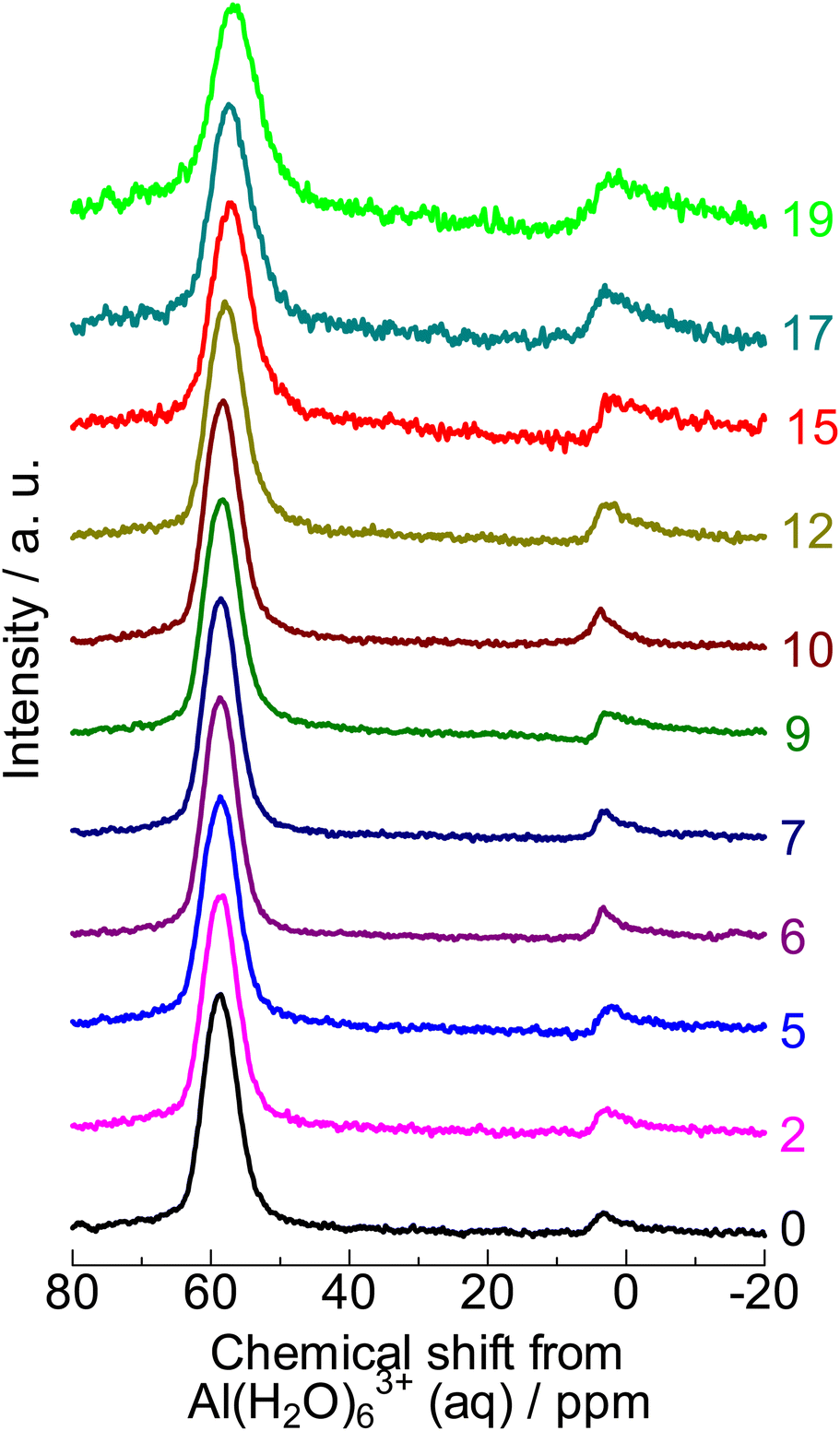 | ||
| Fig. 2 27Al NMR spectra of (0) parent MFI and (2)–(19) silica-alkali-treated MFI. The digits indicate the amount of NaOH used for the silica-alkali treatment in units of mol kgzeolite−1. | ||
 | ||
Fig. 3 Solid recovery ( ), and changes in total ( ), and changes in total ( , from ICP) and framework [ , from ICP) and framework [ , from 29Si NMR (Fig. S2†)] Al contents by silica-alkali treatment of MFI zeolite. *: Recovery = Weight ratio of (recovered solid)/(used zeolite + silica). , from 29Si NMR (Fig. S2†)] Al contents by silica-alkali treatment of MFI zeolite. *: Recovery = Weight ratio of (recovered solid)/(used zeolite + silica). | ||
In conclusion, the parent sample was highly crystalline MFI zeolite, which had a high proportion of framework Al atoms that served as Brønsted acid sites.
Change in textural properties by silica-alkali treatment
The alkali (base) treatment of zeolite partially dissolves the zeolite and forms wormhole-like mesopores, resulting in an increase in the external surface area (total area of meso- and macropore walls).74 Wakihara et al. found that recrystallization proceeded in the region close to the external surface of zeolite in a basic solution containing a silica source.75 We used this silica-alkali treatment method to maintain high crystallinity in the region near the external surface. This gradually changed the properties of the external surface as follows.
Fig. 3 ( ) shows that the solid recovery after the alkali treatment at 453 K decreased when the amount of base (NaOH) increased, indicating that a part of the parent solid (amorphous silica + parent MFI zeolite) was dissolved in the base. The Al content (
 ) gradually increased with increasing NaOH, suggesting that the dissolution of the SiO2 component in the base occurred prior to the dissolution of the Al-containing part. The dissolution of amorphous silica, which had only a pure component, is speculated to occur in the low NaOH concentration region. Meanwhile, the framework Al content (
 ) was almost constant in the region of 0–10 mol kgzeolite−1 of NaOH but increased in higher NaOH amount regions (12 mol kgzeolite−1), suggesting the dissolution of zeolite (aluminosilicate) framework in >12 mol kgzeolite−1 of NaOH. In very high alkali concentration regions (>15 mol kgzeolite−1 of NaOH), the difference between the total and framework Al contents became significantly large, and 27Al NMR (Fig. 2) showed a relatively large proportion of the six-coordinated Al, indicating that some of the Al dislodged from the framework remained in the solid as extra-framework Al species.
XRD (Fig. 1) confirmed that only the MFI crystalline phase was observed throughout the silica-alkali treatments with different NaOH amounts. However, the XRD intensity was suppressed to ca. 68% by the silica-alkali treatment with 2 mol kgzeolite−1 of NaOH, then gradually recovered up to ca. 100% in the region of 7–10 mol kgzeolite−1 of NaOH and finally decreased again with a further increase in the amount of NaOH, as shown in Fig. 4 ( ). The crystallite size was estimated from the width of diffraction (Fig. S3†) using the Scherrer equation,77 as shown in Fig. 4 (
 ). It was maintained in the region of 0–12 mol kgzeolite−1 of NaOH, and further increase in the NaOH amount reduced the crystallite size. The reduction of crystallite size may affect the decrease in XRD intensity in the same region (>12 mol kgzeolite−1 of NaOH); however, the weak intensity of XRD peaks in the low NaOH amount region (2–5 mol kgzeolite−1) was presumably due to low crystallinity.
 | ||
Fig. 4 Intensity ( ) and crystallite size ( ) and crystallite size ( ) estimated using the Scherrer equation63 from the full width at half maximum (Fig. S3†) of the diffraction peak ascribed to the MFI (0 5 1) plane (2θ = 23.1°) observed by X-ray diffraction (Fig. 1). Intensity is normalized by the value on parent MFI (EX-122). ) estimated using the Scherrer equation63 from the full width at half maximum (Fig. S3†) of the diffraction peak ascribed to the MFI (0 5 1) plane (2θ = 23.1°) observed by X-ray diffraction (Fig. 1). Intensity is normalized by the value on parent MFI (EX-122). | ||
Scanning electron microscopy (SEM) analysis (Fig. 5) showed large crystals of parent MFI (0) and small particles around the MFI crystallites treated with 2–5 mol kgzeolite−1 of NaOH. It is presumed that the particles were remaining amorphous silica which was added for the silica-alkali treatment. At 9 mol kgzeolite−1, the small particles (amorphous silica) diminished, and the morphology of the solid was similar to that of the parent MFI. At >12 mol kgzeolite−1, holes (mesopores) with a diameter <10 nm were observed.
 | ||
| Fig. 5 Field emission scanning electron microscope (FE-SEM) images of (0) parent MFI and (2)–(19) silica-alkali-treated MFI. The digit in parentheses indicates the amount of NaOH used for the silica-alkali treatment in units of mol kgzeolite−1. | ||
As shown in Table 1, the micropore volume of parent MFI was high (0.130 cm3 g−1) as stated in the previous subsection, while that of amorphous silica was low (0.013 cm3 g−1). In contrast, the external surface area of parent MFI was low (9 m2 g−1), whereas that of amorphous silica was high (434 m2 g−1). As shown in Fig. 6, the pore diameter of amorphous silica was distributed in the 10–200 nm region; some of them should be ascribed to the slits among the particles.
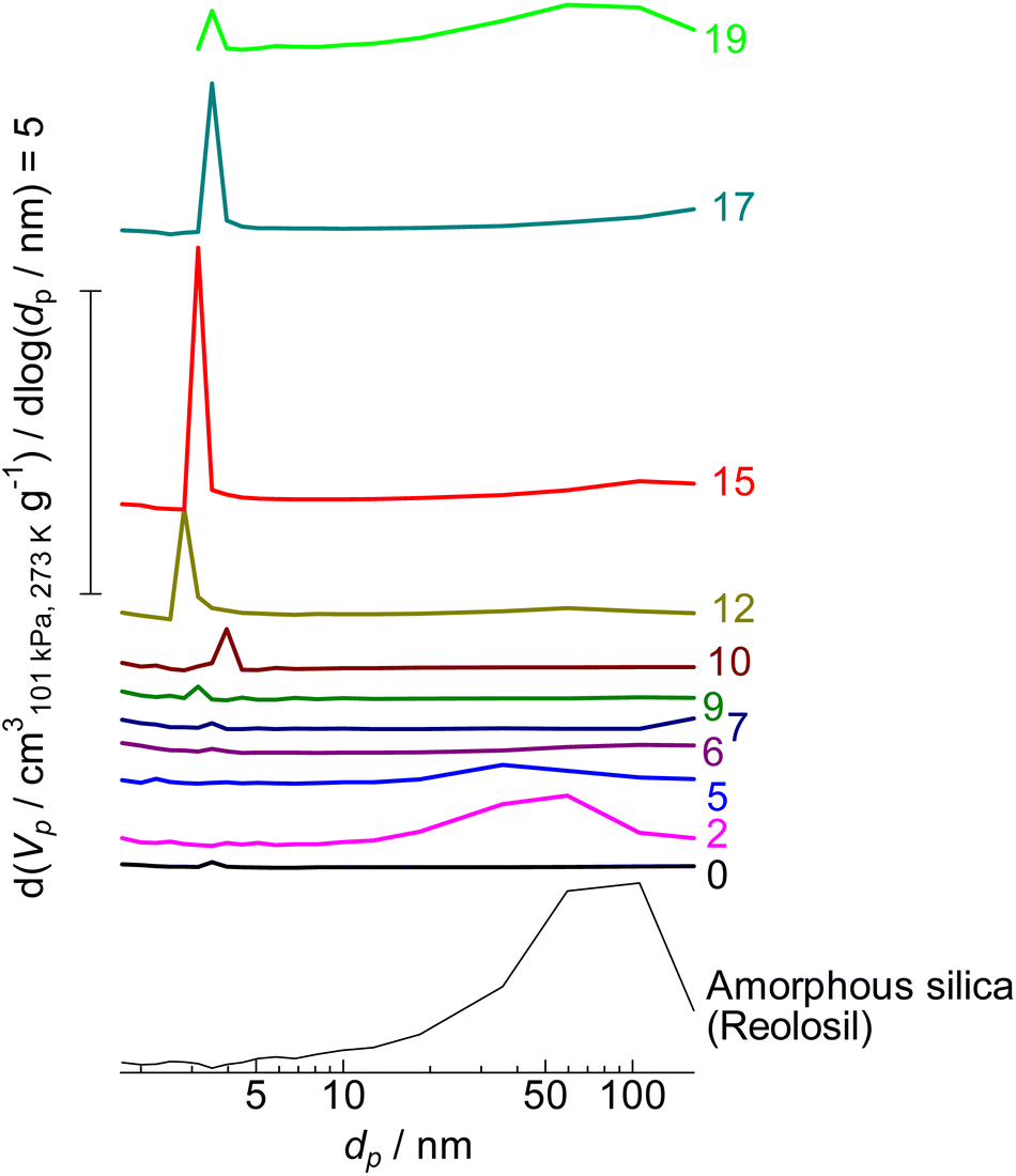 | ||
| Fig. 6 Mesopore diameter distribution of (0) parent MFI and (2)–(19) silica-alkali-treated MFI and amorphous silica (Reolosil) estimated by the BJH method.75 The digits indicate the amount of NaOH used for the silica-alkali treatment in units of mol kgzeolite−1. Vp and dp represent the pore volume and diameter, respectively. | ||
By the alkali treatment with 2–5 mol kgzeolite−1 of NaOH, the micropore volume was decreased, as shown in Fig. 7 ( ), whereas the micropore volume was recovered at >6 mol kgzeolite−1 of NaOH up to the level equivalent to the parent MFI. At 2–5 mol kgzeolite−1 of NaOH, meso- and macropores with diameters of 10–200 nm were observed (Fig. 6), resulting in a high volume of mesopores with diameters >9 nm (Fig. 7,
  ). At 6–9 mol kgzeolite−1 of NaOH, the meso-/macropore volume was low. Fig. 6 shows that, at >10 mol kgzeolite−1 of NaOH, new mesopores with diameters <5 nm, were generated. The distribution peak of pore diameter around 4 nm calculated from the desorption branch is ascribable to the cavitation of nitrogen filling the pore entrances,78 and therefore, the actual diameters on these samples are estimated to be less than the values where the peaks were observed, that is, less than several nanometers. Consequently, the volume of mesopores with diameters <9 nm (Fig. 7,
  ) increased in the region of 10–15 mol kgzeolite−1 of NaOH, with a maximum at 15 mol kgzeolite−1, and decreased with further increases in NaOH.
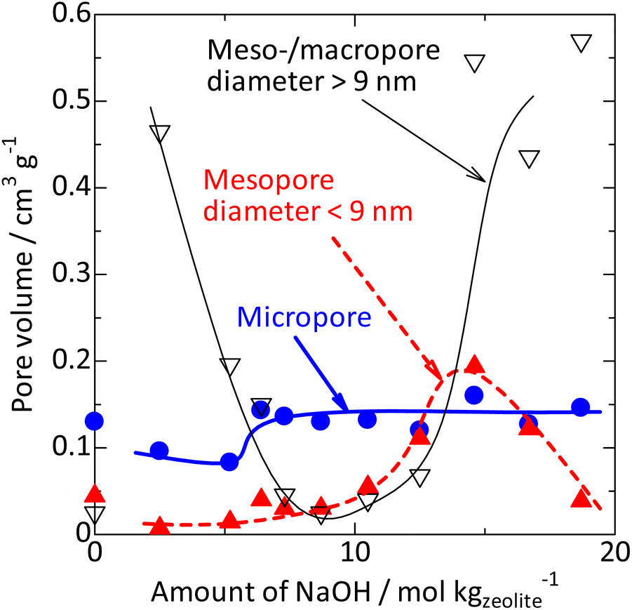 | ||
Fig. 7 Changes in volumes of micropores ( ), mesopores with diameter <9 nm ( ), mesopores with diameter <9 nm ( ) and meso-/macropores >9 nm ( ) and meso-/macropores >9 nm ( ) by silica-alkali treatment of MFI zeolite. The micropore volume was calculated from the amount of nitrogen filling the micropores73,74 from the adsorption branch, while the mesopore volume was estimated using the BJH method75 from the desorption branch (mesopore diameter distribution is shown in Fig. 6), based on the nitrogen adsorption/desorption isotherm at 77 K (Fig. S1†). ) by silica-alkali treatment of MFI zeolite. The micropore volume was calculated from the amount of nitrogen filling the micropores73,74 from the adsorption branch, while the mesopore volume was estimated using the BJH method75 from the desorption branch (mesopore diameter distribution is shown in Fig. 6), based on the nitrogen adsorption/desorption isotherm at 77 K (Fig. S1†). | ||
These observations clarify the changes in the chemical composition and textural properties due to the silica-alkali treatments with different NaOH amounts.
(1) The added amorphous silica was gradually dissolved by the alkali treatment, but at 2–5 mol kgzeolite−1 of NaOH, the amorphous silica remained. The obtained solid was a mixture of amorphous silica and zeolite, as shown by the SEM results and the low crystallinity observed in the XRD; hence its micropore volume was lower than that of the parent MFI. Meso-/macropores with diameters >9 nm, ascribed to the amorphous silica, were observed, whereas mesopores with diameters <9 nm were hardly observed.
(2) At 6–9 mol kgzeolite−1 of NaOH, most of the added amorphous silica was dissolved by alkali treatment, with the resultant solid showing high crystallinity, high micropore volume, and low mesopore volume. This agrees with the fact that the solid mainly consisted of highly crystalline MFI zeolite.
(3) At 10–15 mol kgzeolite−1 of NaOH, wormhole-like mesopores in nanometric dimensions were generated by the alkali treatment of the MFI zeolite in the presence of silicate species dissolved in the solvent.
(4) At >11 mol kgzeolite−1 of NaOH, desilication of the MFI zeolite proceeded to increase the framework Al content. The crystal size was reduced, as shown by XRD.
(5) In the extremely high alkali concentration region (>15 mol kgzeolite−1 of NaOH), destruction of the MFI structure proceeded owing to significant desilication, resulting in the low crystallinity shown by XRD and a large proportion of extra-framework Al species shown by 27Al NMR.
The catalytic activity for 1,3,5-triisopropylbenzene cracking was negligible on the parent zeolite and amorphous silica. It was increased by the silica-alkali treatment in the range of 6–10 mol kgzeolite−1 of NaOH, and high conversion was maintained with further increases in NaOH, as shown in Fig. 8 ( ). These results suggest that the number of the Brønsted acid sites on the external surface was mainly increased by the treatments with 6–10 mol kgzeolite−1 of NaOH. Notably, as explained previously, the silica-alkali-treated MFI with 6–9 mol kgzeolite−1 of NaOH mainly consisted of highly crystalline MFI zeolite. However, the activity of Brønsted acid sites on the external surface was much higher than that of the parent MFI. It is likely that the external surface of the parent MFI was covered by an inert layer, which was highly siliceous and/or amorphous and dissolved in the low alkali concentration region, similar to the amorphous silica.
 | ||
Fig. 8 Change in the external surface area ( ) and catalytic activities for 1,3,5-triisopropylbenzene cracking ( ) and catalytic activities for 1,3,5-triisopropylbenzene cracking ( ) and PP cracking (conversion at 663 K, ) and PP cracking (conversion at 663 K,  ) by silica-alkali treatment of MFI zeolite. ) by silica-alkali treatment of MFI zeolite. | ||
Consequently, we obtained a series of MFI samples whose chemical and external surface properties were modified. As shown in Fig. 8, the activity of Brønsted acid sites on the external surface ( ) was generated at 6–10 mol kgzeolite−1 of NaOH, whereas the external surface area (
 ) was significantly increased in a slightly larger NaOH amount region, 9–15 mol kgzeolite−1. The framework Al content (Fig. 3,
  ) increased in a higher NaOH amount region, >11 mol kgzeolite−1.
Location of PP cracking
It is known that polyolefins, such as PP, are cracked on acidic zeolites. In this study, we attempted to clarify the location of this reaction. We tested the following four hypotheses.(1) In the initial stage of the reaction, the PP molecules are bulky and large; therefore, thermal pyrolysis proceeds in solution without a catalyst, producing polymer fragments.
(2) The PP cracking is first catalysed by the Brønsted acid sites on the external surface of zeolite, and the acid sites within the micropores mainly contribute to the subsequent cracking of the formed medium-length alkanes.
(3) The molecular chains of PP penetrate the micropores of the zeolite, and cracking occurs within the pores. Micropores restrict the diffusion of long molecules; however, when only the end of the molecule is inserted into the pore, diffusion is sufficiently fast because of the short length of the alkyl moiety within the pore. Therefore, the reaction mainly proceeds in micropores close to the pore mouths.
(4) The diffusion of PP is sufficiently faster than the reaction, and the reaction proceeds throughout the micropores.
As shown in the previous subsection, a series of samples with different chemical and external surface properties were obtained, allowing experiments to test the above hypotheses.
At 663 K, cracking of PP (0.25 g) was tested in cyclooctane (1 g) without a catalyst, and negligible reactivity (conversion <1%) was observed. Thus, Hypothesis (1) was rejected. Fig. 8 ( ) shows the change in catalytic activity for PP cracking with respect to the NaOH amount employed for the alkali treatment. Considerable activity was observed on the unmodified MFI. In the region of <9 mol kgzeolite−1 of NaOH, the activity did not increase significantly. In this region, the activity of Brønsted acid sites on the external surface was increased by the silica-alkali treatment, as shown in Fig. 8 (
 ). Thus, the PP cracking activity is not related to the activity of Brønsted acid sites on the external surface. This suggests that the contribution of the acid sites on the external surface to PP cracking was not dominant, which refutes Hypothesis (2). The low activity of the acid sites on the external surface of the MFI type zeolite for the polymer pyrolysis and related reactions has been reported.79 As shown in Fig. 8 (
 ), silica-alkali treatment in the >9 mol kgzeolite−1 region significantly enhanced the PP cracking activity. In this region, the external surface area increased, as shown in Fig. 8 (
 ). Fig. 9 shows a good relationship between the PP cracking activity and the external surface area; simultaneously, its vertical intercept was not zero. These observations suggested that PP cracking predominantly occurred in the micropores of the MFI type zeolite. However, PP cracking activity was not correlated with the framework Al content (increased at >11 mol kgzeolite−1 of NaOH, as shown in Fig. 3
 ), demonstrating that the activity was not dependent on the total Brønsted acidity. This is consistent with the fact that PP cracking occurs in a limited portion of the zeolite. Because a high external surface area enhanced the activity, Hypothesis (3) was supported, and Hypothesis (4) was rejected. It is likely that PP cracking occurred mainly in the micropores, and the region near the pore mouth was mainly responsible for the reaction.
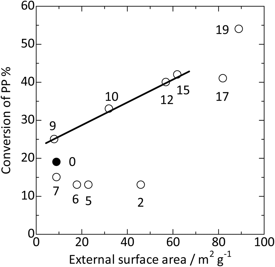 | ||
Fig. 9 Plots of PP conversion at 663 K against external surface area. The conversion on parent MFI is shown using  , whereas those on the silica-alkali-treated MFI samples are shown using , whereas those on the silica-alkali-treated MFI samples are shown using  . The digits indicate the amount of NaOH used for the silica-alkali treatment in units of mol kgzeolite−1. . The digits indicate the amount of NaOH used for the silica-alkali treatment in units of mol kgzeolite−1. | ||
Tsubota et al. also reported the dependency of low-density polyethylene (LDPE) cracking activity on the physicochemical properties of MFI type zeolite to indicate that at least a part of LDPE cracking proceeded in the micropores.37
The kinetic diameter of monomethyl-branched alkane is regarded to be 0.50 nm,80 smaller than the diameter of micropores of MFI type zeolite (10-ring, ca. 0.55 nm).67 Thus, it is reasonable that a part of the PP molecule penetrates the micropores of MFI type zeolite. PP forms a three-dimensional network with entanglements and cross-links consisting of multiple chains, even at a high temperature of 673 K. It is speculated that the head of the molecule penetrated the micropores, and the reaction proceeded in the region close to the pore entrance.
Catalytic activities for cracking of cyclohexane and polypropylene
Hereafter, the effects of the reactant polymer, solvent, catalyst, and reaction temperature will be shown through experiments involving the variation of these variables, as in Entries 1–13 in Table 2.| Entry | Polymer (0.25 g) | Solvent (1 g) | Catalyst (0.05 g) | Reaction temperature/Ka |
|---|---|---|---|---|
| a Reaction time was 1 h in all entries. b Amorphous silica-alumina N631-L. c MFI zeolite treated with silica and alkali (12 molNaOH kgzeolite−1). | ||||
| 1 | No | Cyclooctane | No | 673 |
| 2 | PP | Cyclooctane | No | 673 |
| 3 | No | Cyclooctane | Parent MFI zeolite | 673 |
| 4 | PP | No | Parent MFI zeolite | 673 |
| 5 | PP | Cyclooctane | Parent MFI zeolite | 673 |
| 6 | PP | Hexadecane | Parent MFI zeolite | 673 |
| 7 | PP | Cyclooctane | Beta zeolite | 673 |
| 8 | PP | Cyclooctane | ASAb | 673 |
| 9 | PP | Cyclooctane | Silica-alkali-treated MFI zeolitec | 673 |
| 10 | PP | Cyclooctane | Silica-alkali-treated MFI zeolitec | 693 |
| 11 | LLDPE | Cyclooctane | Silica-alkali-treated MFI zeolitec | 673 |
| 12 | GPPS | Cyclooctane | Silica-alkali-treated MFI zeolitec | 673 |
| 13 | PP | No | Silica-alkali-treated MFI zeolitec | 673 |
As shown in Table 3, heating of pure cyclooctane (Entry 1) and a mixture of cyclooctane and PP (Entry 2) without a catalyst at 673 K for 1 h resulted in negligible conversion of cyclooctane and PP. These indicate that the non-catalytic reaction of alkanes under the experimental conditions has a negligible influence on the discussion below, and the reactions observed below were mainly the catalytic cracking of alkanes and not pyrolysis (non-catalytic thermal decomposition).
| Entry | Reactant | Catalyst | Cyclooctane conversion/% | PP conversion/% |
|---|---|---|---|---|
| 1 | Cyclooctane 1.0 g | No | 2.3 | — |
| 2 | Cyclooctane 1.0 g + PP 0.25 g | No | 1.8 | 4.3 |
| 3 | Cyclooctane 1.0 g | Parent MFI 0.05 g | 24 | — |
| 4 | PP 0.25 g | Parent MFI 0.05 g | — | 57.3 |
Entry 3 in Table 3 shows that the cyclooctane conversion in the presence of parent MFI zeolite as a catalyst was also negligible. It is presumed that because of its bulky molecular shape, cyclooctane did not enter the micropores of the MFI type zeolite. The kinetic diameter of cyclooctane is 0.80 nm,66 larger than the micropore diameter of the MFI type zeolite (ca. 0.55 nm),67 and is in agreement with the inactivity of cyclooctane on the MFI type zeolite. In contrast, heating of pure PP with the parent MFI at 673 K for 1 h (Entry 4) resulted in a high conversion of PP. This agrees with the previous subsection, where the conversion of PP was observed at a slightly lower temperature of 663 K. Thus, pure cyclooctane was not converted, while pure PP was converted using the MFI type zeolite catalyst.
Next, we investigated the reaction of a mixture of PP and cyclooctane on the parent MFI zeolite, as shown in Fig. 10 (Entry 5). The conversion of cyclooctane was very low (3%), and most of the cyclooctane was recovered, while the PP conversion was 28%. Most of the products were liquid (C5-40) hydrocarbons.
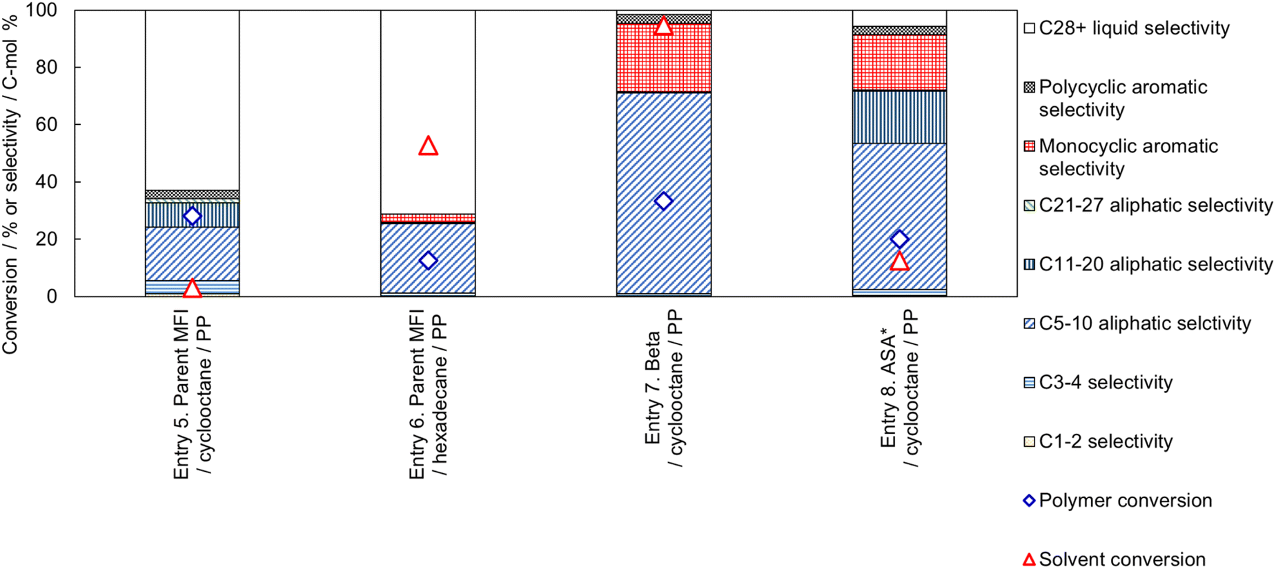 | ||
| Fig. 10 Effect of catalyst and solvent combination on the cracking performance (PP and solvent conversion, and selectivity) of PP (0.25 g) with solvent (1 g) and catalyst (0.05 g) at 673 K for 1 h, where ASA* denotes amorphous silica alumina N631-L. | ||
In Entry 6, a linear alkane (hexadecane) was used as the solvent for PP cracking on the parent MFI zeolite catalyst. The conversion of hexadecane was high (53%), while the PP conversion was suppressed (13%) compared to that in cyclooctane (Entry 5, 28%). The high reactivity of hexadecane on the MFI zeolite suggests that hexadecane penetrates the micropore of MFI and occupies the cavities to suppress the diffusion and conversion of PP molecules. In Entries 7 and 8, catalysts with larger pore sizes (Beta type zeolite and amorphous silica-alumina) showed higher conversions of cyclooctane.
Thus, a high PP conversion and low solvent conversion were observed only when cyclooctane and MFI type zeolite were used as the solvent and catalyst, respectively. The cyclooctane molecule (kinetic diameter 0.80 nm)66 is larger than the micropore of MFI (10-ring, ca. 0.55 nm).67 The use of narrow solvent molecule (hexadecane, whose kinetic diameter should be equivalent to other linear alkanes, 0.43 nm)80 or the use of catalysts with larger pore sizes (Beta: 12-ring, 0.74 × 0.64 nm81 or amorphous silica-alumina N631-L: averagely 4 nm82) showed no selectivity. As explained in the previous subsection, PP cracking proceeds mainly in the micropores, even in the MFI type zeolite, which has the smallest pore size among the presently used catalysts. These facts clearly indicate that the selective reaction of PP in the PP-cyclooctane mixture is caused by reactant shape selectivity. Only molecules smaller than the catalyst pores reacted selectively, while molecules bulkier than the pores were recovered without any reaction.
In the field of polymer cracking, shape selectivity (transition state shape selectivity or product shape selectivity in terms of the reaction mechanism), in which the product distribution is influenced by the porous structure, has been known.70,83 However, to the best of our knowledge, the contribution of reactant shape selectivity to the selective recovery of the solvent has not been reported. Herein, we report the first example of reactant shape selectivity with a microporous catalyst applicable to the chemical recycling of POs without consuming other materials (solvents), as shown in Scheme 1.
Entry 9 in Fig. 11 shows the catalytic performance of silica-alkali-treated MFI (12 molNaOH kgzeolite−1) for PP cracking in cyclooctane. Compared to Entry 5 in Fig. 10 (parent MFI), the PP conversion on the silica-alkali-treated MFI was higher, in agreement with the previous subsection, where the enhancement of activity for PP cracking by the increase in the external surface area was demonstrated. The silica-alkali-treated MFI zeolite was then tested at a slightly higher temperature (693 K) for PP cracking (Entry 10). The PP conversion reached 84%, and the sum of C3-27 aliphatic and monocyclic hydrocarbons selectivities was 79%, meaning that most of the PP was converted into valuable hydrocarbons (LPG, naphtha, kerosene, jet, and diesel), while the cyclooctane conversion was 5% (95% of cyclooctane was recovered). Entry 11 indicates that the selective cracking can be applied to linear low-density polyethylene (LLDPE). On the silica-alkali-treated MFI, 80% of PE (here LLDPE) was converted into mainly C5-10 aliphatic and monocyclic aromatic hydrocarbons, while only 4% of cyclooctane was consumed. Entry 12 shows 95% of PS (here general purpose polystyrene, GPPS) was converted. In this case, it was speculated that the high reactivity of alkylaromatic hydrocarbons resulted in the non-catalytic cracking of PS, and the intermediates reacted on the zeolite. It was confirmed that the cyclooctane conversion was low (4%) in this case also and that selective cracking was applicable to PO and PS. Throughout Entries 9–12, the conversion of cyclooctane was ≤5%, presumably because the micropore of the silica-alkali-treated MFI was also small owing to the MFI framework topology.
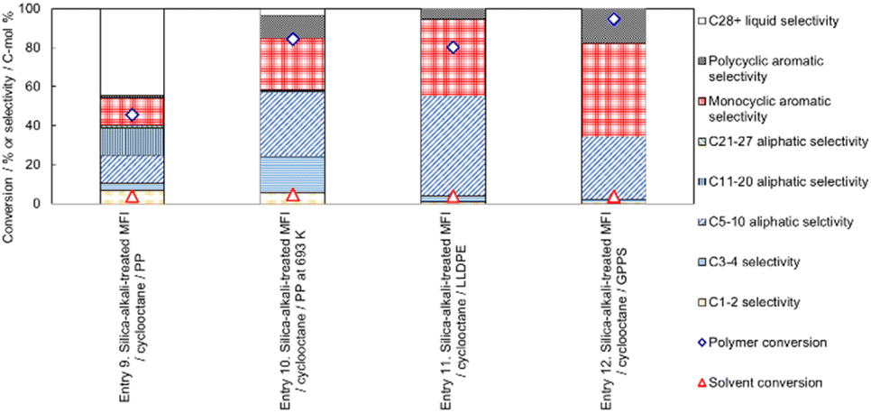 | ||
| Fig. 11 Influence of reaction temperature (Entries 9 and 10, PP cracking at 673 and 693 K, respectively) and influence of reactant polymers (Entries 9, 11 and 12, PP, LLDPE and GPPS cracking, respectively, at 673 K) on polymer cracking performance catalyzed by silica-alkali-treated MFI for 1 h with polymer (0.25 g), cyclooctane as the solvent (1 g) and silica-alkali-treated MFI (prepared with 12 molNaOH kgzeolite−1) as the catalyst (0.05 g). | ||
Fig. 12 shows the effect of the presence of cyclooctane on the selectivity of MFI type zeolite-catalysed PP cracking. Comparison of Entries 4 (without solvent) and 5 (with cyclooctane solvent) shows that, over the parent MFI zeolite catalyst, the use of the solvent significantly increased the C5-20 aliphatic selectivity, whereas C3-4 and C28+ selectivities were suppressed. The decrease in the amount of small (C3-4) hydrocarbons in the presence of cyclooctane is ascribable to the lower reaction progress shown by the lower PP conversion in Entry 5, whereas the decrease in C28+ liquid selectivity reveals that the chain length distribution of products was narrowed by adding cyclooctane. In addition, also on the silica-alkali-treated MFI catalyst, the formation of C3-4 and C28+ hydrocarbons observed without the catalyst (Entry 13) was significantly suppressed in the presence of cyclooctane (Entry 9). The use of solvents for PO cracking contributes to high mass and heat transfer and a homogeneous temperature distribution.54 In the presence of cyclooctane, these effects probably result in a narrow product distribution. A narrow product distribution is necessary to produce a specific region of a hydrocarbon mixture, such as naphtha. Fig. 12 shows the advantage of selectivity achieved by the addition of solvent.
 | ||
| Fig. 12 Comparison of PP cracking performances in the absence (Entries 4 and 13) and presence (Entries 5 and 9) of cyclooctane solvent catalyzed by parent MFI (Entries 4 and 5) and silica-alkali-treated MFI (Entries 13 and 9, prepared with 12 molNaOH kgzeolite−1) at 673 K for 1 h with PP as the polymer (0.25 g), cyclooctane as the solvent (1 g) and a catalyst (0.05 g). | ||
Notably, high selectivity for valuable hydrocarbon compounds was achieved by the reaction in cyclooctane, although cyclooctane itself was not present in the micropores where PO cracking occurred. As mentioned above, the primary role of the solvent in PO cracking is probably to improve thermal and mass transportation. The high selectivity observed in the presence of the solvent outside the reaction field (micropore) indicates that the solvent influenced heat and mass transportation but did not directly influence the chemistry of the active site or the reaction mechanism.
For the short chain alkane (C3-8) cracking, the active site has been clarified to be a strong Brønsted acid site based on the relationship between activity and acidic properties15,43,84–87 and dependence of activation enthalpy on ammonia desorption enthalpy.43,88–91 Since strong Brønsted acidity is required to initiate the reaction, nonclassical carbonium ion formation is considered the initial step in the reaction. C–C bond cleavage of the carbonium ion leads to the formation of a carbenium ion and a short alkane pair, as in reaction (1).92 The former is further decomposed into a shorter carbenium ion and alkene pair, as in reaction (2).12,93 In reaction (2), tertiary carbenium ions are preferred over secondary and primary carbenium ions; thus, alkanes longer than C3 are preferentially formed, unlike non-catalytic radical reactions where all C–C bonds have similar probabilities for cleavage, resulting in the considerable formation of C1-2 fragments.


As PO is an alkane, PO cracking catalysed by acidic zeolite, as shown in the present study, is believed to have the same reaction mechanism. The low selectivity of C1-2 products observed in the reactions catalyzed by the acidic zeolite is consistent with the mechanism. The low activity of ASA (amorphous silica-alumina) with lower Brønsted acid strength23,82 is also in agreement with the speculated mechanism.
In contrast, the PO polymer forms a three-dimensional network. As stated in the previous subsection, it is speculated that the head of a molecule penetrates the micropores to contact the Brønsted acid sites on the pore walls.
This work shows the possibility of a new sustainable method for polymer recycling that does not consume solvents and has high selectivity for the polymer precursor owing to the presence of the solvent. In the small-scale experiments, almost complete recovery of the solvent (>95%) was achieved; however, in a real process the efficiency of several steps, such as separation of the catalyst from the hydrocarbon mixture, separation of the solvent from the product, and purification of the solvent for repeated use, is an issue. Therefore, a life cycle assessment (LCA) of the new process based on a comprehensive evaluation of these efficiencies is necessary in the next research stage.
In addition, we have not yet tested the repeated use of the catalyst; therefore we have no experimental evidence about the life, degradation and recyclability of the catalyst because the recycling test requires complex experimental procedures for the complete collection of the solid catalyst after the reaction in a small reaction tube and separation of the zeolite from the remaining solid polymer in the present reaction system. Therefore, information on the recyclability of the catalyst, energy and resource consumption, and economic efficiency has not been obtained. Here we can discuss only the general trend of the catalytic life of MFI type zeolites, which typically exhibit low solubility in organic media, high stability at temperatures such as 1373 K42 in the low Al concentration region (<ca. 1 mol kg−1). Therefore, it is reasonable to expect that the MFI type zeolite is durable under the reaction conditions (673 K) and the calcination conditions required for the regeneration of active sites (typically 873 K). In addition, compared to other zeolites, MFI type zeolites are known to have a distinct long life for reactions such as the transalkylation91 and cracking94 of hydrocarbons. It is therefore expected that the MFI type zeolites can be repeatedly used for polymer cracking. It is predicted that contaminants in practical waste such as alkaline salts and nitrogen-containing organic compounds with basicity could neutralise the Brønsted acid sites to lose the catalytic activity, and therefore a more important research subject is the applicability and recyclability for the cracking of practical waste POs containing these contaminants. Here we showed only fundamental findings, and the evaluation of the recyclability of the catalyst should be the subject of the next study.
Experimental
Catalyst preparation
NH4-ZSM-5 zeolite (aluminosilicate with an MFI framework topology, Si/Al molar ratio of 15, EX-122 from Mizusawa Industrial Chemicals, Ltd) was used as the parent MFI sample. Table 1 lists its important physicochemical properties. Amorphous silica (Reolosil from Tokuyama Corp.) was used as a feedstock, and its properties are also shown in Table 1.For the silica-alkali treatment, the parent MFI (6 g) was added to a mixture of amorphous silica (4 g), NaOH (FUJIFILM Wako Pure Chemical Corp), and 60 cm3 of ion-exchanged water, stirred in an autoclave at 453 K for 2 h, washed and filtered. The obtained Na-form of zeolite (3.5 g) was twice ion-exchanged with an aqueous solution (300 cm3) of NH4NO3 (24 g) at 338 K for 4 h.
In addition, zeolite β (aluminosilicate with a Beta framework topology, hereafter Beta) and amorphous silica-alumina (hereafter ASA) were employed as catalysts (shown in Table 1).
The NH4-form zeolites were calcined at 813 K for 4 h in air, and the obtained H-form zeolites were used for the PO cracking reaction.
Nitrogen adsorption/desorption isotherms were measured at 77 K using Microtrac-BEL BELSorp-max or BELSorp-mini equipment after evacuation at 573 K for 1 h. The micropore volume was calculated by the t-plot method,95 and the value was confirmed to be similar to the volume of liquid nitrogen showing capillary condensation96,97 at p/p0 = 0.01 and T = 77 K, where p, p0 and T are the pressure of nitrogen, vapor pressure of nitrogen, and temperature, respectively. Here, the volume of pores with diameters 2–50 nm is termed the mesopore volume and was calculated by the Barrett–Joyner–Halenda (BJH) method.98 The external surface area, that is, the area of mesopore and macropore walls in this study, was calculated by the t-plot method.95
Solid-state magic angle spinning nuclear magnetic resonance (MAS NMR) spectra were recorded using a JNM-ECZ 400 instrument (JEOL). The 29Si dipolar decoupling (DD) MAS NMR spectra were measured at 79.42 MHz with a π/2 pulse length of 3.3 μs, a relaxation delay of 30 s, and a spinning frequency of 10 kHz. The 27Al MAS NMR spectra were measured at 104.17 MHz with a π/2 pulse length of 2.97 μs, a relaxation delay of 5.0 s, and a spinning frequency of 14 kHz.
Catalytic cracking of PO
Cyclooctane and hexadecane, purchased from FUJIFILM Wako Pure Chemical Corp., were used as solvents. PP (Mw: weight average molecular weight = 370![[thin space (1/6-em)]](https://www.rsc.org/images/entities/char_2009.gif) 000 and Mn: number average molecular weight = 32000), LLDPE (Mw = 110000 and Mn = 39000), and GPPS (Mw = 240000 and Mn = 15000) were supplied by Japan Petroleum and Carbon Neutral Fuels Energy Center. The molecular weight distributions were analyzed using gel permeation chromatography as detailed in Fig. S4.† The polymer (0.25 g) and catalyst (0.05 g) were placed in a solvent (1 g) in a stainless-steel tube (i.d. 10 mm, volume 3.6 cm3), and the gas phase was purged with N2. It was sealed, and heated using an electric furnace while maintaining the temperature of the thermocouple attached to the stainless-steel tube at 663–693 K for 1 h. After cooling, the stainless-steel tube was connected to a gas syringe, and the volume of the formed gas was measured at atmospheric pressure and room temperature. The gaseous products were analyzed by gas chromatograph with a flame ionization detector (FID-GC). The solid and liquid were then separated, and the liquid was analyzed by an internal standard method using a two-dimensional FID-GC. The solid was washed with pentane, dried, and weighed.
000 and Mn: number average molecular weight = 32000), LLDPE (Mw = 110000 and Mn = 39000), and GPPS (Mw = 240000 and Mn = 15000) were supplied by Japan Petroleum and Carbon Neutral Fuels Energy Center. The molecular weight distributions were analyzed using gel permeation chromatography as detailed in Fig. S4.† The polymer (0.25 g) and catalyst (0.05 g) were placed in a solvent (1 g) in a stainless-steel tube (i.d. 10 mm, volume 3.6 cm3), and the gas phase was purged with N2. It was sealed, and heated using an electric furnace while maintaining the temperature of the thermocouple attached to the stainless-steel tube at 663–693 K for 1 h. After cooling, the stainless-steel tube was connected to a gas syringe, and the volume of the formed gas was measured at atmospheric pressure and room temperature. The gaseous products were analyzed by gas chromatograph with a flame ionization detector (FID-GC). The solid and liquid were then separated, and the liquid was analyzed by an internal standard method using a two-dimensional FID-GC. The solid was washed with pentane, dried, and weighed.
Conclusions
Alkali (NaOH) treatment of the MFI type zeolite in the presence of amorphous silica suggests that PP cracking mainly proceeded in the region near the entrances of the micropores. As previously reported for other hydrocarbon solvents, the use of cyclooctane as a solvent provided a narrow molecular weight distribution of the products in the PP cracking on the MFI catalyst. The combination of the cyclooctane solvent and MFI catalyst resulted in the selective cracking of PP, while most of the cyclooctane was recovered. Using a linear alkane (hexadecane) as the solvent or a catalyst with large pores (Beta type zeolite or amorphous silica-alumina) resulted in high conversion of both solvent and PP. These observations indicate that selective PP cracking is based on the shape selectivity caused by the 10-ring micropores of MFI and the bulky molecular shape of cyclooctane. The products were valuable hydrocarbons. For example, the reaction of PP (0.25 g) with cyclooctane (0.1 g) on silica-alkali-treated MFI (0.05 g) at 693 K for 1 h converted 84% of PP into C3-27 aliphatic and monocyclic aromatic compounds (equivalent to LPG, naphtha, kerosene, jet, and diesel) with 79% selectivity, while 95% of cyclooctane was recovered. The newly discovered shape-selective cracking of PO with solvent recovery will contribute to a sustainable process for the chemical recycling of PO into its precursor, naphtha, with high selectivity facilitated by the presence of solvent without consuming the solvent.Data availability
The data supporting this article have been included as part of the ESI.†Author contributions
Tomohiro Fukumasa: data curation, investigation, methodology, visualization, writing – original draft, Yuya Kawatani: data curation, investigation, methodology, visualization, writing – original draft, Hiroki Masuda: data curation, investigation, methodology, visualization, Ikuto Nakashita: data curation, investigation, Ryusei Hashiguchi: data curation, investigation, Masanori Takemoto: investigation, methodology, visualization, Satoshi Suganuma: methodology, validation, writing – review & editing, Etsushi Tsuji: methodology, validation, writing – review & editing, Toru Wakaihara: conceptualization, funding acquisition, methodology, project administration, writing – review & editing, and Naonobu Katada: conceptualization, data curation, formal analysis, funding acquisition, methodology, project administration, validation, visualization, writing – original draft, writing – review & editing.Conflicts of interest
There are no conflicts to declare.References
- R. Geyer, J. R. Jambeck and K. L. Law, Sci. Adv., 2017, 3, e1700782 CrossRef PubMed.
- R. Noll, in Laser-Induced Breakdown Spectroscopy: Fundamentals and Applications, ed. R. Noll, Springer Berlin Heidelberg, Berlin, Heidelberg, 2012, pp. 275–386, DOI:10.1007/978-3-642-20668-9_14.
- C. G. Schirmeister and R. Mulhaupt, Macromol. Rapid Commun., 2022, 43, 2022247 CrossRef PubMed.
- I. Vollmer, M. J. F. Jenks, M. C. P. Roelands, R. J. White, T. Harmelen, P. Wild, G. P. Laan, F. Meirer, J. T. F. Keurentjes and B. M. Weckhuysen, Angew. Chem., Int. Ed., 2020, 59, 15402–15423 CrossRef CAS PubMed.
- Y. Nakaji, M. Tamura, S. Miyaoka, S. Kumagai, M. Tanji, Y. Nakagawa, T. Yoshioka and K. Tomishige, Appl. Catal., B, 2021, 285, 119805 CrossRef CAS.
- P. Zhao, W. Guo, Z. Gui, J. Jiang, Z. Zhu, J.-J. Li, L. Zhao, J. Zhou and Z. Xi, ACS Sustain. Chem. Eng., 2024, 12, 5738–5752 CrossRef CAS.
- P. B. Venuto and R. T. Habib, Catal. Rev.:Sci. Eng., 1978, 18, 1 CrossRef CAS.
- A. Corma, J. B. Monton and A. V. Orchilles, Appl. Catal., 1985, 16, 59–74 CrossRef CAS.
- H. G. Karge, V. Mavrodinova, Z. K. Zheng and H. K. Beyer, Appl. Catal., 1991, 75, 343–358 CrossRef CAS.
- A. R. Songip, T. Masuda, H. Kuwahara and K. Hashimoto, Energy Fuels, 1994, 8, 136–140 CrossRef CAS.
- V. B. Kazansky, M. V. Frash and R. A. vanSanten, Appl. Catal., A, 1996, 146, 225–247 CrossRef CAS.
- S. M. Babitz, M. A. Kuehne, H. H. Kung and J. T. Miller, Ind. Eng. Chem. Res., 1997, 36, 3027–3031 CrossRef CAS.
- S. Kotrel, M. P. Rosynek and J. H. Lunsford, J. Phys. Chem. B, 1999, 103, 818–824 CrossRef CAS.
- P. Borges, R. R. Pinto, M. A. N. D. A. Lemos, F. Lemos, J. C. Vedrine, E. G. Derouane and F. R. Ribeiro, J. Mol. Catal. A: Chem., 2005, 229, 127–135 CrossRef CAS.
- N. Katada, S. Nakata, S. Kato, K. Kanehashi, K. Saito and M. Niwa, J. Mol. Catal. A: Chem., 2005, 236, 239–245 CrossRef CAS.
- F. Lonyi, A. Kovacs and J. Valyon, J. Phys. Chem. B, 2006, 110, 1711–1721 CrossRef CAS PubMed.
- N. Katada, H. Igi, J. H. Kim and M. Niwa, J. Phys. Chem. B, 1997, 101, 5969–5977 CrossRef CAS.
- N. Katada, Y. Kageyama and M. Niwa, J. Phys. Chem. B, 2000, 104, 7561–7564 CrossRef CAS.
- M. Niwa, N. Katada and K. Okumura, in Characterization and Design of Zeolite Catalysts, Springer, Heidelberg, 2010, pp. 9–27 Search PubMed.
- H. Li, S. Yang, A. Riisager, A. Pandey, R. S. Sangwan, S. Saravanamurugan and R. Luque, Green Chem., 2016, 18, 5701–5735 RSC.
- N. Katada, Mol. Catal., 2018, 458, 116–126 CrossRef CAS.
- N. Katada, K. Suzuki, T. Noda, G. Sastre and M. Niwa, J. Phys. Chem. C, 2009, 113, 19208–19217 CrossRef CAS.
- N. Katada, K. Yamamoto, M. Fukui, K. Asanuma, S. Inagaki, K. Nakajima, S. Suganuma, E. Tsuji, A. Palcic, V. Valtchev, P. S. Petkov, K. Simeonova, G. N. Vayssilov and Y. Kubota, Microporous Mesoporous Mater., 2022, 330, 111592 CrossRef CAS.
- R. C. Mordi, J. Dwyer and R. Fields, Polym. Degrad. Stab., 1994, 46, 57–62 CrossRef CAS.
- J. Aguado, J. L. Sotelo, D. P. Serrano, J. A. Calles and J. M. Escola, Energy Fuels, 1997, 11, 1225–1231 CrossRef CAS.
- S. C. Cardona and A. Corma, Appl. Catal., B, 2000, 25, 151–162 CrossRef CAS.
- E. Y. Hwang, J. R. Kim, J. K. Choi, H. C. Woo and D. W. Park, J. Anal. Appl. Pyrolysis, 2002, 62, 351–364 CrossRef CAS.
- J. R. Kim, Y. A. Kim, J. H. Yoon, D. W. Park and H. C. Woo, Polym. Degrad. Stab., 2002, 75, 287–294 CrossRef CAS.
- A. Marcilla, A. Gómez, J. A. Reyes-Labarta, A. Giner and F. Hernández, J. Anal. Appl. Pyrolysis, 2003, 68–69, 467–480 CrossRef CAS.
- Q. Zhou, L. Zheng, Y. Z. Wang, G. M. Zhao and B. Wang, Polym. Degrad. Stab., 2004, 84, 493–497 CrossRef CAS.
- A. Durmus, S. N. Koç, G. S. Pozan and A. Kasgöz, Appl. Catal., B, 2005, 61, 316–322 CrossRef CAS.
- K. Pyra, K. A. Tarach and K. Gora-Marek, Appl. Catal., B, 2021, 297, 120408 CrossRef CAS.
- A. Santoso, A. Sholikhah, S. Sumari, M. R. Asrori, A. R. Wijaya, R. Retnosari and I. B. Rachman, J. Renewable Mater., 2022, 10, 2781–2789 CAS.
- J. Mensah, P. H. Yan, A. Rawal, A. F. Lee, K. Wilson, N. Robinson, M. L. Johns, E. Kennedy and M. Stockenhuber, ChemCatChem, 2024, 16, e202300884 CrossRef CAS.
- S. D. Xu, J. H. Tang and L. Fu, Langmuir, 2024, 40, 3984–4000 CrossRef CAS PubMed.
- N. H. Nazarloo, O. Zabihi, K. Shirvanimoghaddam, M. Ahmadi and M. Naebe, ChemCatChem, 2024, 16, e202300909 CrossRef.
- S. Tsubota, S. Kokuryo, K. Tamura, K. Miyake, Y. Uchida, A. Mizusawa, T. Kubo and N. Nishiyama, Catal. Sci. Technol., 2024, 14, 1369–1374 RSC.
- Z. Yu, H. Wu, Y. Li, Y. Xu, H. Li and S. Yang, Ind. Eng. Chem. Res., 2020, 59, 16970–16986 CrossRef CAS.
- N. Katada, T. Kanai and M. Niwa, Microporous Mesoporous Mater., 2004, 75, 61–67 CrossRef CAS.
- N. Katada, T. Takeguchi, T. Suzuki, T. Fukushima, K. Inagaki, S. Tokunaga, H. Shimada, K. Sato, Y. Oumi, T. Sano, K. Segawa, K. Nakai, H. Shoji, P. Wu, T. Tatsumi, T. Komatsu, T. Masuda, K. Domen, E. Yoda, J. N. Kondo, T. Okuhara, Y. Kageyama, M. Niwa, M. Ogura, M. Matsukata, E. Kikuchi, N. Okazaki, M. Takahashi, A. Tada, S. Tawada, Y. Kubota, Y. Sugi, Y. Higashio, M. Kamada, Y. Kioka, K. Yamamoto, T. Shouji, Y. Arima, Y. Okamoto and H. Matsumoto, Appl. Catal., A, 2005, 283, 63–74 CrossRef CAS.
- D. Barthomeuf, J. Phys. Chem., 1993, 97, 10092–10096 CrossRef CAS.
- S. P. Zhdanov, N. N. Feoktistova, N. I. Kozlova and I. G. Polyakova, Bull. Acad. Sci. USSR, Div. Chem. Sci., 1985, 34, 2463–2466 CrossRef.
- N. Katada, S. Sota, N. Morishita, K. Okumura and M. Niwa, Catal. Sci. Technol., 2015, 5, 1864–1869 RSC.
- A. Marcilla, J. C. García-Quesada, S. Sánchez and R. Ruiz Femenia, J. Anal. Appl. Pyrolysis, 2005, 74, 387–392 CrossRef CAS.
- D. Fraczak, Przem. Chem., 2018, 97, 299–304 CAS.
- I. Muhammad and G. Manos, ACS Sustain. Chem. Eng., 2022, 10, 15824–15837 CrossRef CAS.
- S. B. Zhang, M. Li, Z. Y. Zuo and Z. Q. Niu, Green Chem., 2023, 25, 6949–6970 RSC.
- R. Tiwari, N. Azad, D. Dutta, B. R. Yadav and S. Kumar, Sci. Total Environ., 2023, 881, 163433 CrossRef CAS PubMed.
- Y. W. Yang, R. M. Pan and S. A. Yong, Fuel, 2024, 361, 130734 CrossRef CAS.
- Q. Xu, J. H. Zhu, B. C. Wu, G. Z. Jin, Y. P. Liu, A. H. Huang, C. Y. Tian and Y. T. Luo, J. Energy Inst., 2024, 113, 101556 CrossRef CAS.
- L. An, Z. L. Kou, R. J. Li and Z. Zhao, Catalysts, 2024, 14, 212 CrossRef CAS.
- K. d. J. Mesquita, J. C. Pinto and H. P. Pacheco, Macromol. React. Eng., 2024, 18, 2300061 CrossRef CAS.
- W. Zhang, H. Yao, R. Khare, P. R. Zhang, B. D. Yang, W. D. Hu, D. Ray, J. Z. Hu, D. M. Camaioni, H. M. Wang, S. Kim, M. S. Lee, M. L. Sarazen, J. G. Chen and J. A. Lercher, Angew. Chem., Int. Ed., 2024, 63, e202319580 CrossRef CAS PubMed.
- J. M. Arandes, J. Erena, M. J. Azkoiti, D. Lopez-Valerio and J. Bilbao, Fuel Process. Technol., 2004, 85, 125–140 CrossRef CAS.
- Y. Peng, X. Wang, L. Fan, Q. Zhang, X. Cui, X. Tian, Q. Wu, K. Cobb, R. Ruan, H. Tu, J. Yang and Y. Wang, J. Cleaner Prod., 2023, 418, 138039 CrossRef CAS.
- J. Wang, J. C. Jiang, Y. J. Sun, Z. P. Zhong, X. B. Wang, H. H. Xia, G. H. Liu, S. S. Pang, K. Wang, M. Li, J. M. Xu, R. Ruan and A. J. Ragauskas, Energy Convers. Manage., 2019, 200, 112088 CrossRef CAS.
- A. C. Jerdy, L. Trevisi, M. Monwar, M. A. González-Borja, R. Abbott, L. Lobban and S. Crossley, Appl. Catal., B, 2023, 337, 122986 CrossRef CAS.
- S. Wu, K. Xu, L. Jiang and L. Wang, AASRI Procedia, 2014, 7, 3–7 CrossRef.
- S. H. Ng, Energy Fuels, 1995, 9, 216–224 CrossRef CAS.
- J. Aguado, D. P. Serrano, G. Vicente and N. Sanchez, J. Polym. Environ., 2006, 14, 375–384 CrossRef CAS.
- D. J. Machhi, B. Modhera and P. A. Parikh, J. Mater. Cycles Waste Manage., 2023, 25, 3005–3020 CrossRef CAS.
- Y. B. Zhao, X. D. Lv and H. G. Ni, Chemosphere, 2018, 209, 707–720 CrossRef CAS PubMed.
- Q. Zhao, L. An, C. Li, L. Zhang, J. Jiang and Y. Li, Compos. Sci. Technol., 2022, 224, 109461 CrossRef CAS.
- T. Thiounn and R. C. Smith, J. Polym. Sci., 2020, 58, 1347–1364 CrossRef CAS.
- T. Christoff-Tempesta and T. H. Epps, ACS Macro Lett., 2023, 12, 1058–1070 CrossRef CAS PubMed.
- L. M. Chua, I. Hitchcock, R. S. Fletcher, E. M. Holt, J. Lowe and S. P. Rigby, J. Catal., 2012, 286, 260–265 CrossRef CAS.
- R. Le Van Mao, S. T. Le, D. Ohayon, F. Caillibot, L. Gelebart and G. Denes, Zeolites, 1997, 19, 270–278 CrossRef CAS.
- O. Akin, R. J. Varghese, A. Eschenbacher, J. Oenema, M. S. Abbas-Abadi, G. D. Stefanidis and K. M. Van Geem, J. Anal. Appl. Pyrolysis, 2023, 172, 106036 CrossRef CAS.
- H. Shafaghat, S. Gulshan, A. C. Johansson, P. Evangelopoulos and W. H. Yang, Appl. Surf. Sci., 2022, 605, 154734 CrossRef CAS.
- M. M. Hasan, N. Batalha, G. Fraga, M. H. M. Ahmed, L. Pinard, M. Konarova, S. Pratt and B. Laycock, Sustainable Energy Fuels, 2022, 6, 1587–1602 RSC.
- A. Farooq, S. Valizadeh, G. H. Rhee, J. Lee, J. Jae, S. C. Jung, W. H. Chen and Y. K. Park, Energy Convers. Manage., 2022, 261, 115652 CrossRef CAS.
- Y. M. Kim, J. Jeong, S. Ryu, H. W. Lee, J. S. Jung, M. Z. Siddiqui, S. C. Jung, J. K. Jeon, J. Jae and Y. K. Park, Energy Convers. Manage., 2019, 195, 727–737 CrossRef CAS.
- Y. K. Park, M. Z. Siddiqui, Y. Kang, A. Watanabe, H. W. Lee, S. J. Jeong, S. Kim and Y. M. Kim, Catalysts, 2018, 8, 656 CrossRef.
- M. Ogura, S. Y. Shinomiya, J. Tateno, Y. Nara, M. Nomura, E. Kikuchi and M. Matsukata, Appl. Catal., A, 2001, 219, 33–43 CrossRef CAS.
- T. Wakihara, A. Ihara, S. Inagaki, J. Tatami, K. Sato, K. Komeya, T. Meguro, Y. Kubota and A. Nakahira, Cryst. Growth Des., 2011, 11, 5153–5158 CrossRef CAS.
- K. S. W. Sing, Pure Appl. Chem., 1985, 57, 603–619 CrossRef CAS.
- A. L. Patterson, Phys. Rev., 1939, 56, 978–982 CrossRef CAS.
- C. J. Rasmussen, A. Vishnyakov, M. Thommes, B. M. Smarsly, F. Kleitz and A. V. Neimark, Langmuir, 2010, 26, 10147–10157 CrossRef CAS PubMed.
- C. Hu, H. Zhang, S. Wu and R. Xiao, Energy Convers. Manage., 2020, 210, 112678 CrossRef CAS.
- H. H. Funke, A. M. Argo, J. L. Falconer and R. D. Noble, Ind. Eng. Chem. Res., 1997, 36, 137–143 CrossRef CAS.
- T. O. Bok, E. P. Andriako, E. E. Knyazeva and I. I. Ivanova, RSC Adv., 2020, 10, 38505–38514 RSC.
- N. Katada, Y. Kawaguchi, K. Takeda, T. Matsuoka, N. Uozumi, K. Kanai, S. Fujiwara, K. Kinugasa, K. Nakamura, S. Suganuma and M. Nanjo, Appl. Catal., A, 2017, 530, 93–101 CrossRef CAS.
- J. Gancedo, H. Q. Li, J. S. Walz, L. Faba, S. Ordóñez and G. W. Huber, Appl. Catal., A, 2024, 669, 119484 CrossRef CAS.
- N. Katada, Y. Kageyama, K. Takahara, T. Kanai, H. A. Begum and M. Niwa, J. Mol. Catal. A: Chem., 2004, 211, 119–130 CrossRef CAS.
- J. S. Jung, T. J. Kim and G. Seo, Korean J. Chem. Eng., 2004, 21, 777–781 CrossRef CAS.
- T. Noda, K. Suzuki, N. Katada and M. Niwa, J. Catal., 2008, 259, 203–210 CrossRef CAS.
- K. Okumura, T. Tomiyama, N. Morishita, T. Sanada, K. Kamiguchi, N. Katada and M. Niwa, Appl. Catal., A, 2011, 405, 8–17 CrossRef CAS.
- J. Y. Shen and A. Auroux, in Fluid Catalytic Cracking Vi: Preparation and Characterization of Catalysts, ed. M. Occelli, 2004, vol. 149, pp. 35–70 Search PubMed.
- N. Katada, K. Suzuki, T. Noda, W. Miyatani, F. Taniguchi and M. Niwa, Appl. Catal., A, 2010, 373, 208–213 CrossRef CAS.
- M. Niwa, K. Suzuki, N. Morishita, G. Sastre, K. Okumura and N. Katada, Catal. Sci. Technol., 2013, 3, 1919–1927 RSC.
- K. Nakamura, R. Mizuta, S. Suganuma, E. Tsuji and N. Katada, Catal. Commun., 2017, 102, 103–107 CrossRef CAS.
- S. Kotrel, H. Knözinger and B. C. Gates, Microporous Mesoporous Mater., 2000, 35–36, 11–20 CrossRef CAS.
- W. M. Zhang and P. G. Smirniotis, J. Catal., 1999, 182, 400–416 CrossRef CAS.
- B. Bensafi, N. Chouat and F. Djafri, Coord. Chem. Rev., 2023, 496, 215397 CrossRef CAS.
- A. Galarneau, F. Villemot, J. Rodriguez, F. Fajula and B. Coasne, Langmuir, 2014, 30, 13266–13274 CrossRef CAS PubMed.
- D. Mitsuyoshi, K. Kuroiwa, Y. Kataoka, T. Nakagawa, M. Kosaka, K. Nakamura, S. Suganuma, Y. Araki and N. Katada, Microporous Mesoporous Mater., 2017, 242, 118–126 CrossRef CAS.
- K. Nakajima, S. Suganuma, E. Tsuji and N. Katada, React. Chem. Eng., 2020, 5, 1272–1280 RSC.
- E. P. Barrett, L. G. Joyner and P. P. Halenda, J. Am. Chem. Soc., 1951, 73, 373–380 CrossRef CAS.
- (a) S. Brunauer, P. H. Emmett and E. Teller, J. Am. Chem. Soc., 1938, 60, 309–319 CrossRef CAS; (b) R. Geyer, J. R. Jambeck and K. L. Law, Sci. Adv., 2017,(3), e1700782 CrossRef PubMed.
Footnote |
| † Electronic supplementary information (ESI) available: Compositions of solutions after PP cracking experiments, nitrogen adsorption isotherms, 29Si NMR spectra and full width at half maximum of XRD. See DOI: https://doi.org/10.1039/d4su00484a |
| This journal is © The Royal Society of Chemistry 2025 |