
 Open Access Article
 This Open Access Article is licensed under a
 Creative Commons Attribution 3.0 Unported Licence
Integrated fractionation and templating of lignin using magnesium for sustainable and tailored porous carbon†
Angelo Robiños ab,
Hao Zhangb,
Zekra Mousavia,
Tor Lauréna,
Jan-Henrik Småtta,
Leena Hupaa,
Chunlin Xu*b and
Johan Bobacka*a
ab,
Hao Zhangb,
Zekra Mousavia,
Tor Lauréna,
Jan-Henrik Småtta,
Leena Hupaa,
Chunlin Xu*b and
Johan Bobacka*a
aLaboratory of Molecular Science and Engineering, Faculty of Science and Engineering, Åbo Akademi University, Henriksgatan 2, 20500 Åbo-Turku, Finland. E-mail: johan.bobacka@abo.fi
bLaboratory of Natural Materials Technology, Faculty of Science and Engineering, Åbo Akademi University, Henriksgatan 2, 20500 Åbo-Turku, Finland. E-mail: chunlin.xu@abo.fi
First published on 24th April 2025
Abstract
The heterogeneity of lignin presents challenges in fabricating lignin-derived carbon materials with well-defined structures. This study investigated the use of magnesium as a fractionating agent via precipitation to modify the heterogeneity of lignin, which was then integrated with the MgO templating technique to produce functionalized porous carbon with tailored porosity. First, alkaline-dissolved spruce kraft lignin was precipitated under varied pH conditions, resulting in magnesium–lignin (MgL) complexes with different degrees of higher molecular weight lignin fractions. These complexes underwent a pre-heating treatment at 700 °C, facilitating the formation of nano-sized MgO domains within the carbon matrix. Acid leaching was subsequently carried out, followed by a high-temperature post-heating treatment at 1400 °C to remove the magnesium oxide (MgO), leaving behind nano-sized porous structures. The variation in fractionation pH affected the form of magnesium in the MgL complex, influencing MgO crystal formation during pyrolysis and allowing for tunable pore sizes in the resulting carbon during templating. Additionally, the presence of magnesium enhanced carbon yields after heat treatment at 1400 °C, with stoichiometric optimizations involving magnesium and pH increasing yields from 35% to 49%. These findings establish the groundwork for precise and more sustainable design of lignin-derived porous carbon materials.
Sustainability spotlightLignin is often burned as a low-grade fuel, wasting its rich chemical potential and contributing to unsustainable practices. Our work presents a technique that simultaneously fractionates lignin and incorporates a Mg salt to create well-defined pore structures while enhancing carbonization yields. By stoichiometrically optimizing mixture components, we effectively applied chemical science to improve the resource efficiency and minimize waste. This process aligns with UN Sustainable Development Goal 12: Responsible Consumption and Production, paving the way for greener industrial transformation. Moreover, the resulting porous carbon materials can be applied in energy storage, catalysis, and environmental remediation, further paving the way for achieving UN Sustainable Development Goals 6 (Clean Water and Sanitation), 7 (Affordable and Clean Energy), and 13 (Climate Action). |
1 Introduction
Humankind faces pressing challenges today in the areas of climate change, environmental pollution, and energy crisis. These bring out an increasing need to discover economically viable and environmentally friendly solutions. Carbon and its derivatives are highlighted as ideal materials for developing solutions to these problems due to their applicability in energy storage, catalysis, adsorption, and gas capture and storage.1 This versatility stems from their conductivity, stability, high specific surface area, and customizable pore structure.2–4 Currently, state-of-the-art carbon materials are predominantly derived from petroleum refining, which is unsustainable and the main contributor to the challenges mentioned above.5 Meanwhile, lignocellulosic materials, particularly lignin, hold great promise as precursors for carbon production. With its high carbon content (>60%), exceptional tunability due to its abundance of oxygen and aromatic functional groups, and low cost, lignin stands out as a highly desirable and sustainable choice.4,6 Such conditions boosted research towards improving the lignin refining processes and subsequent valorization. In fact, carbon materials derived from various lignin have demonstrated exceptional performance across different applications, such as batteries,7,8 supercapacitors,9–11 catalysts,12–14 and environmental remediation.15,16A significant challenge, however, exists when utilizing lignin as a carbon precursor – its inherent heterogeneity, reflected in its broad molecular weight distribution (polydispersity) and complex chemical structure. This leads to uneven properties and performance when it is used in the preparation of chemicals and materials, significantly hindering its high-value utilization.17 The primary solution identified for this dilemma is through lignin fractionation, where lignin is segregated into distinct fractions with reduced heterogeneity.17,18 Various fractionation methods such as pH-controlled precipitation, partial solubility in solvents, and membrane technologies have been developed. These processes are crucial in the effective engineering of lignin to value-added materials with reproducible properties and improved performance.17 Indeed, carbon materials derived from lignin have shown improvement in their target performance after fractionation because of the increase in their uniformities and shifts in their molecular weight distributions.18–21 However, when producing carbon materials, the feasibility of large-scale production is also crucial. Current lignin fractionation techniques often fall short in this regard. Relying on organic solvents and acids can be costly and hazardous, and their recovery and treatment can be quite energy intensive.17 Fractionation through membrane filtration, on the other hand, offers significant industrial potential due to its operational ease and environmental benefits, but the expensive instrumentation and the poor solubility of most commercial lignin are major limitations.17,22 A fractionation technique that limits the use of aforementioned chemicals and equipment, while producing large quantities of more uniform lignin for high-value carbon production, is therefore desired.
Nonhazardous and abundant metal ions, such as zinc, iron, and magnesium, have shown significant potential as fractionating agents for this purpose. Their ability to precipitate dissolved lignin or co-precipitate with it and provide functionalization at the same time has been extensively demonstrated, enabling applications in supercapacitors,9,11 catalysts,23,24 adsorbents,25–27 and hydrogels.28 Most of these studies, however, focus primarily on the ability of metal ions to facilitate synthesis, particularly in “one-step” or “one-pot” processes,9,26,27 with an emphasis on structuring the material as desired. Systematic understanding and control over the metal–lignin interactions during fractionation itself is still lacking, which limits the optimization of the structure and functionality of the resulting materials. Additionally, the effects of metal fractionation on lignin molecular weights are rarely linked to the ensuing synthesis or material yields.
Given that the pH, as well as the nature of the metal ion, significantly influence metal–lignin interactions,29,30 the aforementioned gaps could be addressed by exploring pH-controlled variations in metal–lignin complexation and fractionation processes. In this study, magnesium ions (Mg2+) were used because they precipitate effectively to form Mg(OH)2 within the pH range of 10–13, which encompasses the same conditions for lignin precipitation, as the pH goes down, enabling co-precipitation or magnesium–lignin complexation.29,31 Additionally, free Mg2+ has shown to coagulate lignin down to pH 6.32 After fractionating the complex out of the mixture, magnesium can then be easily removed and recycled using a dilute acid, simultaneously isolating the lignin fraction. More importantly, if magnesium is retained and the magnesium–lignin complex is subjected to carbonization, it could undergo dehydration and form a magnesium oxide (MgO) template with its surrounding oxygen. Upon removal of this template with dilute acid, the resulting homogeneous porous carbons can be utilized for various applications.33–35 This integrated fractionation–templating technique not only improves the reproducibility of carbon properties and makes the process more streamlined but would also facilitate a clearer analysis and understanding of the fractionation–structure relationship. The main goal of this study was therefore to assess both the lignin fractionation using magnesium and the subsequent production of porous carbon via MgO templating. Special focus was placed on understanding the underlying mechanisms during the fractionation process, and how this can be leveraged to enhance material properties. Additionally, stoichiometric optimization of lignin, additives, and metal ions was explored to further improve the carbon yield.
2 Experimental section
2.1 Materials
Spruce kraft lignin (SKL, LignoBoost®), provided by Metgen Oy (Kaarina, Finland), was stored in a refrigerator and subsequently acclimated to room temperature prior to every use. LignoBoost® lignin was used in this study for its availability, consistent quality, low salt content and high purity.36 These characteristics provide a controlled environment, allowing better assessment of magnesium–lignin interactions compared to other technical lignins with more complex compositions and structures. The hydroxyl group content of lignin was determined with 31P NMR spectroscopy using the protocol from Meng et al.,37 as detailed in the ESI.† The aliphatic–OH, phenolic–OH, and carboxylic–OH groups were quantified as 2.4, 3.7, and 0.4 mmol g−1, respectively, resulting in a total of 6.5 mmol g−1 lignin–OH groups. Hydrogen peroxide (H2O2, 30%), hydrochloric acid (HCl, 30%), and nitric acid (HNO3, 65%) were procured from Merck. 2-Chloro-4,4,5,5-tetramethyl-1,3,2-dioxaphospholane (C6H12ClO2P, TMDP, 95%), chromium(III) acetylacetonate (Cr(C5H7O2)3, Cr(acac)3, 97%), deuterated chloroform (CDCl3, 99.8% D), N-hydroxy-5-norbornene-2,3-dicarboxylic acid imide (C9H9NO3, e-HNDI, 97%) lithium bromide (LiBr, ≥99%), magnesium sulfate (MgSO4, ≥98%), and pyridine (C5H5N, anhydrous, 99.8%) were obtained from Sigma-Aldrich. Dimethyl sulfoxide (C2H6OS, ≥99.9%) and sodium hydroxide (NaOH, 98.3%) were acquired from Fisher Chemical. Ethanol (C2H5OH, ≥99.8%) was bought from VWR Chemicals. Deionized water (ELGA Purelab Ultra, resistance: 18.2 MΩ cm) was used throughout the work.2.2 Magnesium–lignin (MgL) complex preparation
Dispersions of SKL with 10% (w/v) concentration were prepared by mixing 4 g SKL samples with 40 mL of NaOH solutions with varied concentrations at room temperature, as outlined in Table 1 and Scheme 1. The NaOH concentrations were chosen to ensure the dissolution of the majority of lignin, as described by Melro et al.31 MgL1 and MgL2 were made less alkaline than MgL3 and MgL4. The dispersions were mixed for 24 h under constant agitation with a nutating mixer (VWR, USA). Using a centrifuge (Hermle Z36HK, USA), the resulting mixtures were then separated for 1 h at 10![[thin space (1/6-em)]](https://www.rsc.org/images/entities/char_2009.gif) 000 rpm and 20 °C. The obtained supernatants were transferred to glass vessels, and 200 mL of deionized water was added to each of them to prepare the dissolved lignin solutions for precipitation and concurrent fractionation.
000 rpm and 20 °C. The obtained supernatants were transferred to glass vessels, and 200 mL of deionized water was added to each of them to prepare the dissolved lignin solutions for precipitation and concurrent fractionation.
| Complex | Lignin, Lignin–OH | Solvent (NaOH, OH−) | Precipitant (MgSO4, Mg2+, HCl, H+) | Remarksa |
|---|---|---|---|---|
| a Based on Mg(OH)2 formation, accounting for added HCl. | ||||
| MgL1 | 10.0% (w/v), 26.0 mmol | 1.0% (w/v), 10.0 mmol | 6% (w/v), 24.9 mmol Mg, —, — | Excess Mg2+ |
| MgL2 | 10.0% (w/v), 26.0 mmol | 1.0% (w/v), 10.0 mmol | 6% (w/v), 24.9 mmol Mg, 0.25 M, 12.5 mmol | Excess Mg2+ and H+ |
| MgL3 | 10.0% (w/v), 26.0 mmol | 2.5% (w/v), 25.0 mmol | 6% (w/v), 24.9 mmol Mg, —, — | Excess OH− |
| MgL4 | 10.0% (w/v), 26.0 mmol | 2.5% (w/v), 25.0 mmol | 6% (w/v), 24.9 mmol Mg, 0.25 M, 12.5 mmol | Excess Mg2+ |
 | ||
| Scheme 1 Schematic illustration of the preparation of MgL complexes and derived carbons in this work. | ||
Solutions for precipitation consisted of 6% (w/v) MgSO4 dissolved in either deionized water or 0.25 M HCl to allow the formation of different lignin fractions based on their interactions with Mg2+ under varying pH conditions. The concentration of MgSO4 was chosen based on the quantity of lignin–OH groups that could theoretically interact with Mg2+. Furthermore, the amounts of lignin, Mg2+ and OH− ions mixed in MgL3 and MgL4 were stoichiometrically balanced for the formation of Mg(OH)2, while an excess of Mg2+ was added in MgL1 and MgL2. The process was facilitated by a dosing system (905 Titrando, Metrohm, Switzerland), which ensured the controlled delivery of the precipitants. Exactly 50 mL of the precipitant was added to the dissolved lignin solution in a span of 1 h, at regular intervals of 4 s, while under continuous stirring. Each addition consisted of the same volume of precipitant. At the end of precipitation, another 1 h was allotted for ripening of the solids, wherein the mixtures were just stirred, and no additional precipitant was added. The pH was monitored throughout the whole process using a pH electrode (Solitrode 6.022.100, Metrohm, Switzerland). Nitrogen gas flow was also kept above the solution surface to prevent the interference from atmospheric CO2. A tightly sealed Teflon™ (PTFE) lid covered the vessel and had designated holes for the pH electrode, dosing connections, and gas source. Following the ripening, the resulting solid–liquid mixtures were centrifuged at 10000 rpm for 30 min at 20 °C, yielding a clear phase separation. The solid residues were washed multiple times with deionized water and afterwards dried in an oven at 105 °C. The resulting solid magnesium–lignin complexes (MgL1, MgL2, MgL3, and MgL4) were then ground and subjected to characterization experiments and further processing. To ensure reproducibility, the synthesis was conducted twice, with parallel measurements performed for verification.
2.3 Magnesium–lignin (MgL) complex carbonization
The MgL complexes were initially carbonized at 700 °C for 1 h, with a heating rate of 10 °C min−1 under a nitrogen gas stream (500 mL min−1) in a tube furnace (VST 12/600, Carbolite, United Kingdom), followed by cooling to room temperature. The carbonized complexes were then designated as pre-washed MgL (MgL-AW, including MgL1-PW, MgL2-PW, MgL3-PW, and MgL4-PW). Subsequently, they were crushed and ground with an agate mortar and pestle before being immersed in 1.0 M HCl solution under a fume hood. The resulting suspensions were sonicated for 1 h and then left to age for 24 h at room temperature with constant stirring. Following that, they were filtered with a 0.2 μm filter (47 mm Nuclepore™ Polycarbonate Track-Etched Membranes, Cytiva Whatman™, United Kingdom), and the residues underwent washing with deionized water and ethanol before drying at 40 °C under vacuum. At this stage, the carbonized complexes will be referred to as acid-washed MgL (MgL-AW, including MgL1-AW, MgL2-AW, MgL3-AW, and MgL4-AW). Finally, high temperature MgL carbons (MgL-HT, including MgL1-HT, MgL2-HT, MgL3-HT, and MgL4-HT) were obtained by subjecting the acid-washed MgL samples to a second carbonization at 1400 °C for 1 h. This was done in a high-temperature tube furnace (ETF 50/17, Entech, Sweden), under an argon gas stream (350 mL min−1), at a rate of 4 °C min−1. The samples were then cooled to room temperature.2.4 Thermal analysis
Thermogravimetric analysis (TGA), differential thermogravimetry (DTG), and normalized heat flow (NHF) analysis of the MgL complexes were carried out using a thermogravimetric analyzer (SDT 650, TA Instruments, USA), with a heating rate of 10 °C min−1 from 30 °C to 900 °C and nitrogen (100 mL min−1) as the purge gas. The samples were oven-dried at 105 °C overnight prior to the analysis.2.5 Fourier transform infrared spectroscopy
The infrared (IR) spectra of MgL complexes were obtained using attenuated total reflection Fourier transform infrared (ATR-FTIR) spectroscopy (Nicolet iS50, Thermo Fisher, USA) with 64 scans and covering the wavenumber range 4000–500 cm−1. The samples were mounted directly atop the ATR unit and measured with the pressure stamp.2.6 Molecular weight distribution
The molecular weight distribution and polydispersity of the MgL complexes were determined based on the protocol by Zinovyev et al.38 using a high-performance size exclusion chromatograph (1100/1260 series, Agilent, USA) equipped with a refractive index detector (Optilab™ Refractive Index Detector, Wyatt Technology, USA) and a MALS detector (DAWN™ Multi-angle Light Scattering, Wyatt Technology, USA). First, the magnesium in the complexes was removed by washing with dilute HCl until the pH of the washings reached around 2.5. Subsequently, the magnesium-free lignin was freeze-dried and dissolved in 0.05 M lithium bromide (LiBr) in dimethyl sulfoxide (DMSO) at a concentration of 5 mg mL−1. The mixtures were stirred overnight and then filtered over a 0.44 μm nylon syringe filter (Agilent, USA) before injection into the column (X-stream H2O 103 Å, Jordi Labs, USA). Based on the described protocol, the absolute molecular weights (M) can be determined without relying on standard calibrations using the following equation:
 | (1) |
2.7 CHN analysis
The C, H, and N elemental compositions of MgL complexes, MgL-PW, MgL-AW, and MgL-HT, were analyzed using a CHN analyzer (FLASH 2000, Thermo Scientific, USA).2.8 Inductively coupled plasma-optical emission spectrometry (ICP-OES)
The S, Mg, and Na elemental compositions of MgL complexes, MgL-PW, MgL-AW, and MgL-HT, were analyzed using an ICP-OES analyzer (Optical Emission Spectrometer Optima 5300 DV, PerkinElmer, USA). Approximately 0.1 g of each solid sample was dissolved by adding 5 mL of concentrated HNO3 and 1 mL H2O2, followed by digestion in a microwave digester (Multiwave 3000, Anton Paar, Austria) for 65 minutes. After digestion, the solutions were diluted with 50 mL deionized water. Calibrations of the ICP-OES instrument were then performed with 1, 5, and 20 mg L−1 in 1.5% HNO3 of SpectraScan standards (SS-1152 for S and SS-028226 for Mg and Na). When the measured concentrations of the samples exceeded the calibration range, the samples were further diluted. The elemental content in each sample was then calculated based on the initial sample weight and dilution factor.2.9 X-ray diffraction (XRD)
The diffraction patterns of MgL-PW, MgL-AW, and MgL-HT were acquired using an X-ray diffractometer (AXS D8 Discover, Bruker, Germany) with CuKα radiation (λ = 1.5406 Å) under 40 kV accelerating voltage and 40 mA emission current. The diffraction angle (2θ) range was set from 10° to 80°, with an increment of 0.04° and data collection of 10 s per step. The interlayer spaces between graphene layers (d002) were then calculated from the (002) plane values using the Bragg equation:
 | (2) |
 | (3) |
2.10 Scanning electron microscopy (SEM)
The surface morphology and topography as well as the elemental components of the MgL complexes, MgL-PW, MgL-AW, and MgL-HT were investigated using a scanning electron microscope (LEO Gemini 1530, Zeiss/LEO, Germany), equipped with an X-ray detector (UltraDry Silicon Drift, Thermo Scientific, USA) operating at an accelerating voltage of 2.70 kV. The samples were ground, and the powders were adhered to carbon tapes and analyzed without further preparation.2.11 Transmission electron microscopy (TEM)
The internal structures of MgL-HT were analyzed using a transmission electron microscope (JEM-1400 PLUS, JEOL Ltd, Japan) in bright-field mode with an accelerating voltage of 80 kV. The samples were diluted in ethanol to a 1.0% (w/v) concentration before analysis.2.12 Raman spectroscopy
The Raman spectra of MgL-HT carbon samples were acquired using a Raman microscope (Renishaw Ramascope, UK). An Ar-ion laser with an excitation wavelength of 514 nm and a laser power of 25.0 mW, spanning the wavenumber region from 2000 to 800 cm−1, was used. The spectrometer was calibrated against a Si standard (520 cm−1). For the measurements, less than 1 mg of each sample was mounted on a standard microscopy glass slide, and the spectra were collected directly without any pre-treatment. The Raman spectra were deconvoluted into one Gaussian-shaped band (D3, at about 1500 cm−1) and four Lorentzian-shaped bands (G, D1, D2 and D4 at about 1580, 1350, 1620, and 1200 cm−1, respectively) according to the methodology suggested by Sadezky et al.39 and using a Raman deconvolution software.402.13 Nitrogen physisorption
Nitrogen physisorption measurements were carried out using a gas sorption analyzer (Autosorb-1, Quantachrome Instruments, USA). Prior to analysis, the samples were degassed at 150 °C for 15 h to remove all physically adsorbed materials trapped in the pores. The apparent surface area (SABET) was determined by the Brunauer–Emmett–Teller (BET) method41 in the pressure range of 0.05–0.20P/P0. The pore size distribution was assessed using the quenched solid density functional theory (QSDFT) model42 to account for the surface geometrical inhomogeneity. The total volume of pores was calculated at a relative pressure of P/P0 = 0.99.3 Results and discussion
3.1 MgL complex formation and fractionation
In general, lignin exhibits colloidal characteristics under alkaline conditions. However, when the pH of the solution is lowered, the negatively charged groups in lignin undergo protonation. This eliminates the electrostatic repulsive forces responsible for stabilizing lignin as a dispersion, resulting in the precipitation or coagulation of lignin.43 As shown in Fig. 1a–d, this process was monitored by potentiometrically measuring the pH while adding MgSO4 and HCl to the SKL dissolved in NaOH. Also, as depicted in Fig. 1e, there are three potential mechanisms by which Mg2+ can precipitate or coagulate lignin out of the solution: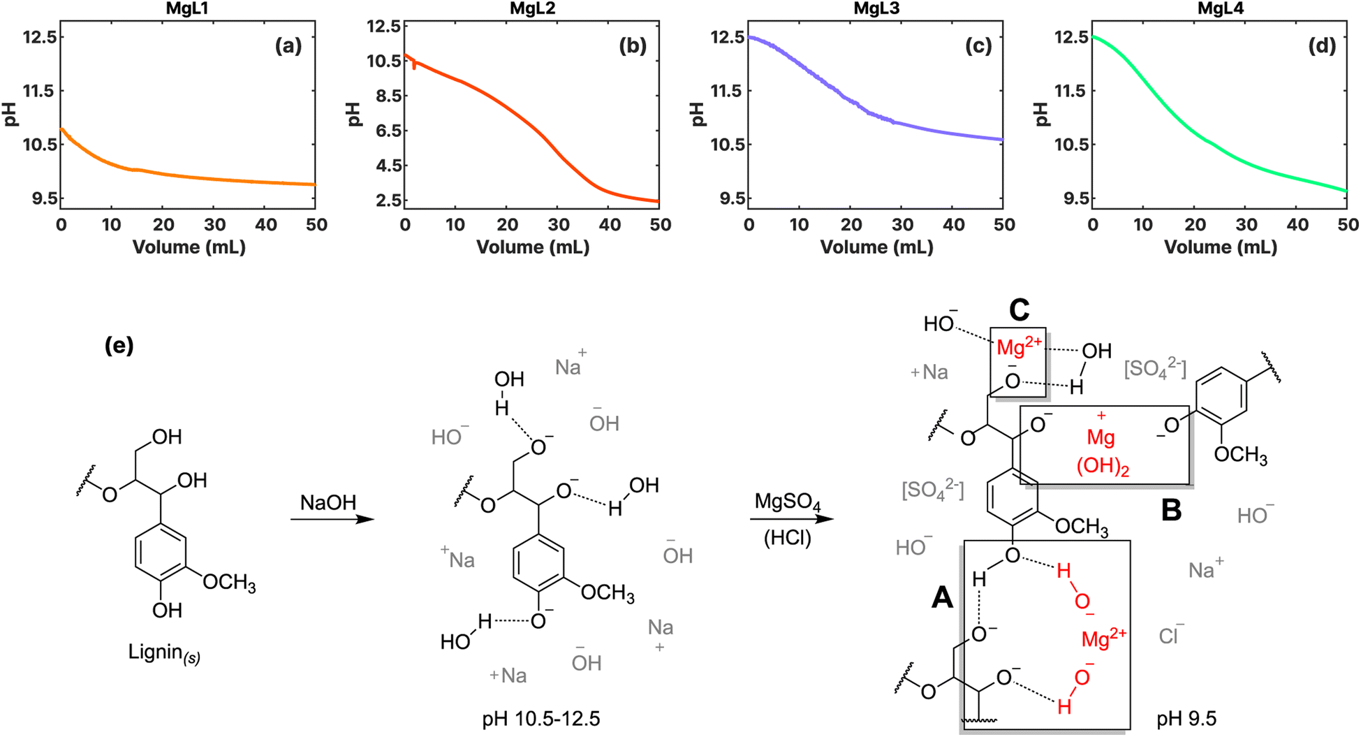 | ||
| Fig. 1 Potentiometric (pH) curves illustrating the formation of magnesium–lignin (MgL) complexes through lignin precipitation: (a) MgL1; (b) MgL2; (c) MgL3; (d) MgL4. (e) Proposed mechanism of lignin precipitation or coagulation by magnesium set at a final pH of 9.5. | ||
(A) Mg2+ ions form solid Mg(OH)2 under alkaline conditions, leading to the decrease in the pH of the solution, the gradual resurgence of H-bonding in lignin, and subsequently to the indirect precipitation of lignin out of the solution.
(B) Mg(OH)2 is slightly positively charged below its isoelectric point, which is at pH 12. This allows it to interact with the negatively charged groups of lignin (pKa > pH),29 serving as the nuclei to which lignin can coagulate around. Ragnar et al.44 determined and summarized the pKa values of lignin groups.
(C) As the pH is further reduced, either through the formation of Mg(OH)2 or by the addition of H+, the system will attempt to equilibrate the solution by dissolving the previously formed Mg(OH)2. This process liberates the Mg2+ ions, which can then interact with the negatively charged groups of lignin, facilitating their coagulation.32
In MgL1 and MgL2, where less quantity of NaOH was used to dissolve the lignin, the majority of the initially added OH− ions were used to deprotonate the lignin. Consequently, only a limited amount of OH− ions remained accessible for the precipitation of Mg(OH)2. Calculations presented in the ESI† also reveal that the precipitation of Mg(OH)2 is not favorable at approximate pH levels below 10.35, a range prevalent in most of the events in MgL1 and MgL2 systems. The main mechanism in these two systems under alkaline conditions is therefore lignin coagulation due to free Mg2+ ions (Fig. 1e(C)). In the case of MgL2, wherein an excess of H+ ions was introduced, an intricate interplay of reactions arose. This may have involved both the coagulation of free Mg2+ ions with lignin as well as the stabilization of free Mg2+ ions under acidic solutions. During this process, Mg2+ ions may have become trapped inside the evolving lignin matrix as the pH is continuously decreased. For MgL3 and MgL4 solutions, initially having pH levels around 12.5, precipitation took place as soon as Mg2+ was added (Fig. 1e(A)). As the pH of the solution gradually lowered, the formed Mg(OH)2, which became slightly positively charged, coagulated lignin (Fig. 1e(B)) until the hydroxide parts dissociated and only the Mg2+ remained interacting with lignin (Fig. 1e(C)). Such is the case observed in MgL4. Conversely, in the MgL3 solution, where no excess H+ ions were added, the pH did not drop below 10.35. Thus, more of the Mg(OH)2 precipitate remained in it compared to the other systems. Notably, the results obtained here aligns well with the remarks outlined in Table 1.
FTIR spectra (Fig. 2a) were obtained to study the dried MgL complexes. Most of the differences were found in the peak intensities, which decreased after lignin dissolution. This trend was notable across several peaks that are assigned as follows:45–47 (1) the peaks at 1594, 1510, and 1425 cm−1 correspond to ring stretching and the peaks at 1265 and 1211 cm−1 are attributed to ring bending. These peaks arose from aromatic groups that are commonly found in lignin. (2) The peak at 2935 cm−1 indicates C–H stretching of the OCH3 group and CH2OH group and those at 1452 and 1462 cm−1 are due to C–H bending of OCH3 and CH2OH groups. (3) The peak at 1078 cm−1 represents the C–O deformation in secondary alcohols and aliphatic ethers, and the peak at 1030 cm−1 signifies C–O deformation of methoxy groups. (4) The peak at 1145 cm−1 corresponds to C–H in-plane deformation, and the peak at 850 cm−1 indicates C–H out-of-plane deformation, both for lignin G-units. In addition, the wide peak at 3330 cm−1 is attributed to the aromatic and aliphatic hydroxyl groups in the material and is typically broad if H-bonding is present.47 Out of the complexes, MgL2 had the broadest peak at 3330 cm−1, comparable to that of SKL. In contrast, MgL1, MgL3, and MgL4 did not have very apparent peaks at 3330 cm−1 due to the absence of H-bonding when they were dissolved,31 precipitated, and coagulated. The minute peak in 3700 cm−1, observed solely in MgL3, is recognized as a brucite lattice vibration,48,49 which signifies the presence of remaining Mg(OH)2 in a crystalline form. The peak observed at 1709 cm−1 corresponds to the C![[double bond, length as m-dash]](https://www.rsc.org/images/entities/char_e001.gif) O stretching of unconjugated carbonyls. Upon the dissolution of lignin with NaOH, this peak disappeared, possibly due to enolate formation resulting from nucleophilic attacks from the abundant OH−. In addition, the absence of the peak at 1365 cm−1, which is due to the ring stretching of lignin units with a hydroxyl group at the 4-position (phenyl–OH), also suggests deprotonation by OH− ions.47 In both cases, the peaks reoccurred only in MgL2 after protonation with excess acid.
O stretching of unconjugated carbonyls. Upon the dissolution of lignin with NaOH, this peak disappeared, possibly due to enolate formation resulting from nucleophilic attacks from the abundant OH−. In addition, the absence of the peak at 1365 cm−1, which is due to the ring stretching of lignin units with a hydroxyl group at the 4-position (phenyl–OH), also suggests deprotonation by OH− ions.47 In both cases, the peaks reoccurred only in MgL2 after protonation with excess acid.
 | ||
| Fig. 2 (a) FTIR spectra of MgL complexes. (b) Refractive index molecular weight distributions of lignin fractions obtained from magnesium fractionation. | ||
The absolute molecular weights of magnesium-liberated lignin fractions were determined by size-exclusion chromatography. Fig. 2b shows the comparison among the four MgL complexes and the original SKL, normalized by the peak height on the differential refractive index (RI) response. Table 2 presents various molecular weight parameters. Generally, higher molecular weights (HMWs) were obtained for MgL complexes compared to SKL. Specifically, the MgL1, MgL3, and MgL4 lignin fractions show peak molecular weights being shifted to the left, corresponding to earlier elution times, with differences among them attributed to the fractionation pH. This suggests that the magnesium and acid were unable to precipitate the lower molecular weight (LMW) fractions, either due to their higher solubility because of their smaller sizes or the propensity of HMW lignin to precipitate Mg2+ and H+ first, at the operating pH values. This behaviour aligns with the findings of Sundin and Hartler,29 who reported that the precipitation of kraft lignin by metal cations could only partially precipitate lignin with molecular weights between 1 and 5 kDa, while LMW lignin at <1 kDa does not precipitate at all. Consequently, HMW lignin molecules became the most abundant after fractionation. This behavior also corresponds to the acid precipitation method, where HMW lignin tends to precipitate first when the acid is added at higher pH values, around 10 to 11. This occurs due to the reduced solubility of the HMW lignin after their weaker acidic groups (which have a higher pKa) become protonated.50 Meanwhile, some portion of the HMW lignin, eluting around 20 min, are also missing in the MgL1, MgL3, and MgL4 lignin fractions. This is most likely not due to fractionation but rather to the insufficient dissolution of lignin at the utilized NaOH concentration, as displayed in Fig. S2.† Moreover, the highly alkaline environment is very conducive to the breakdown of lignin to LMW compounds.51,52
| Sample | Mn (kDa) | Mp (kDa) | Mw (kDa) | Mw/Mn (kDa) |
|---|---|---|---|---|
| MgL1 | 8.8 ± 1.1 | 11.6 ± 5.3 | 46 ± 22 | 5.1 ± 1.9 |
| MgL2 | 11.8 ± 0.9 | 7.3 ± 2.6 | 648 ± 194 | 55.6 ± 20.6 |
| MgL3 | 13.4 ± 5.5 | 13.0 ± 4.5 | 51 ± 5 | 4.2 ± 2.1 |
| MgL4 | 7.4 ± 1.1 | 7.8 ± 2.0 | 30 ± 4 | 4.0 ± 0.1 |
| SKL | 6.7 ± 0.8 | 5.6 ± 0.2 | 36 ± 2 | 5.4 ± 0.4 |
On the other hand, MgL2 exhibited a different behavior compared to the three fractions discussed earlier. This is primarily due to the formation of aggregates, clusters of lignin molecules that appear as a single particle during light scattering, thereby resulting in earlier elution of peaks (as shown in Fig. S3†) and subsequently to HMW values. Lignin aggregation is mainly driven by hydrogen bonding, resulting from acid precipitation of lignin, as well as π–π stacking due to HOMO–LUMO interactions between aromatic groups in the lignin.53,54 As elaborated in Table 1, a certain amount of acid that resulted in an excess was added to MgL2, rendering it highly susceptible to aggregation. Meanwhile, the results presented in Table 2 for MgL2 served as definitive confirmation of the presence of aggregates in this sample, as unreasonably HMW values were obtained.
In terms of the resulting heterogeneity, the polydispersity indices of MgL lignin fractions decreased, with the exemption of MgL2, in comparison to SKL (Table 2). Previous studies have found that the molecular weight and polydispersity of lignin affected the resulting yield and structures of pyrolysis products. The study by Guo et al.55 on alkali lignin pyrolysis revealed that while evolution temperature ranges and the volatile product species were not significantly affected, the final residual weight appeared to be impacted to a certain extent by the molecular weight and polydispersity of the fractions. Higher residual weights were then observed when fractions were more polydisperse, and this has also been reported by other studies.56,57 Furthermore, it was found that the ratio of evolved gases and functional groups obtained from the fractions after pyrolysis can vary depending on the molecular weight of the precursor lignin. Lignin which have LMW distributions had also been found to be graphitized earlier than HMW lignin, as the temperature was increased.58 The removal of the LMW fraction after fractionation with magnesium can be advantageous for energy and environmental applications as it prevented the growth of graphitized carbons with morphologies that featured mirror-like surfaces with higher densities and low porosities. In fact, when synthesizing carbon nanofibers, it was found that HMW and lower polydispersity enhanced the overall mechanical performance.59
3.2 High temperature treatment of MgL complexes
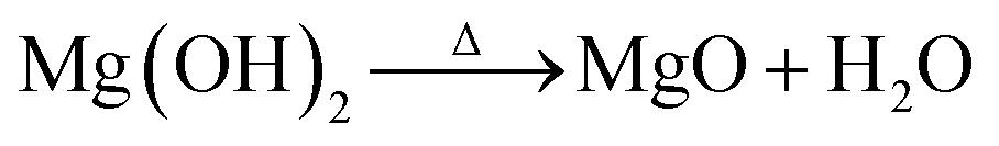
The thermal stabilities of MgL complexes along with SKL and Mg(OH)2 were analyzed, and the results are presented in Fig. 3a–c as TGA, DTG, and NHF curves. All the precipitated MgL complexes have much higher percentage of residual weight than SKL, with MgL3 retaining the most material, followed by MgL4, MgL1, and MgL2. Contrary to what was mentioned in the earlier section, the results of TGA show no clear relationship between the residual weights and molecular weights, nor polydispersities. This discrepancy is mainly attributed to the presence of magnesium in different forms, influenced by the fractionation pH. Data from prior studies also suggest that carbon precursors impregnated with magnesium demonstrated better resistance to mass loss at higher temperatures.25,33,60 This can be understood better by examining Mg(OH)2 and lignin pyrolysis reactions, as the magnesium in the complexes closely resembles the Mg(OH)2 structure, either after precipitating with hydroxide or after interacting with charged oxygen groups in lignin. Mg(OH)2 dehydrates to form MgO around 327 °C,61 in accordance with the following equation:
 | (4) |
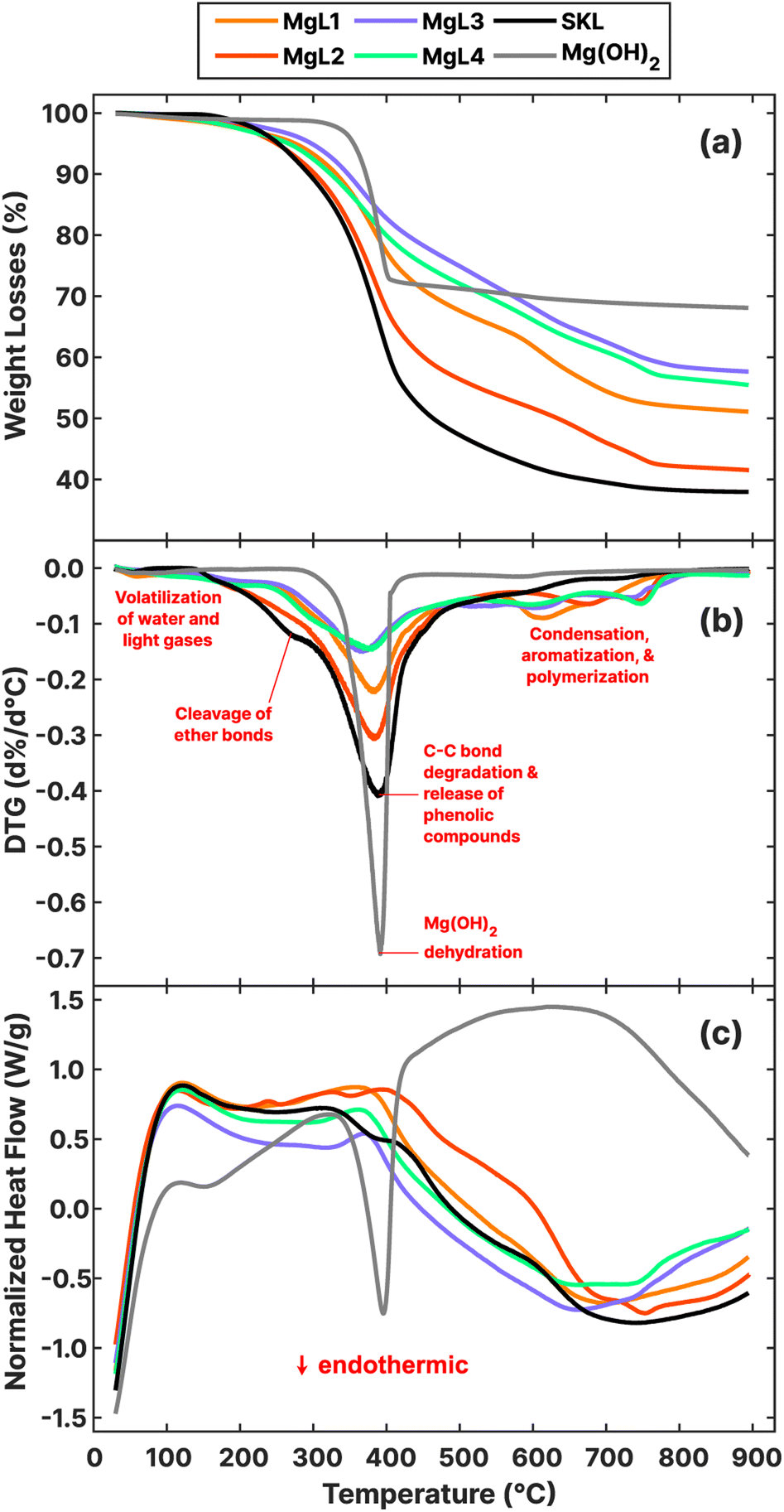 | ||
| Fig. 3 (a) Thermogravimetric analysis (TGA), (b) differential thermogravimetry (DTG), and (c) normalized heat flow (NHF) curves of MgL complexes, SKL, and Mg(OH)2. | ||
Pyrolysis and gasification reactions in lignin, on the other hand, occur over a large temperature range, with the highest rate of decomposition around 360–400 °C. The reactions can be divided into two stages: alkyl chain conversion and breaking of some unit linkages (150–420 °C) and aromatic substituent conversion and charring (380–800 °C).62 Throughout this process, magnesium and its forms affect how lignin is thermally decomposed. In the TGA and DTG results, the first major deviation from the source SKL can be observed in the first stage of pyrolysis around 200–400 °C, where the percentage weight losses significantly decreased for all MgL complexes, culminating in the DTG peaks around 360–390 °C. Previously reported analyses63–65 of the pyrolysis of model lignin dimers revealed that α- and β-ether bonds, which are the most common linkages in lignin, representing more than 56%,66 are readily cleaved at these temperature ranges. Specifically, the cleaving of α-ether (Ph), β-ether (Ph, Cγ–OH), and α, β-ether (Ph) have onset temperatures of 200 °C, 250 °C, and 250 °C, respectively, generating quinone methide intermediates and radical species. The suggested cleaving mechanism involves the heterolytic C–O separation initiated by the donation of an electron pair from the O–H in the phenolic structure.64,67,68 However, this mechanism is less feasible in the presence of magnesium, which localizes the negative charge of the phenolate anion, as depicted for α-ether (Ph) in Fig. 4. Such is the case for MgL1, MgL3, and MgL4, where their phenyl–H have been dissociated, as previously discussed in their FTIR spectra. In MgL2, magnesium was not so successful in inhibiting the cleaving mechanism because the phenyl–H was protonated following the addition of excess acid.
 | ||
| Fig. 4 Cleaving mechanism of α-ether (Ph) linkages in lignin and lignin complexed with magnesium during pyrolysis. | ||
Starting at 300 °C, C–C bonds between alkyl chains become unstable and react, and compounds with one to three carbon atoms such as methane, acetaldehyde, and carboxylic acids form. These reactions provoke the rupture of the branches between aromatic rings and are responsible for the highest decomposition rate around 360–390 °C, and the consequent release of phenolic compounds such as p-cresol, guaiacol, and syringol.62 Coinciding with this is the endothermic dehydration of Mg(OH)2, as shown in the NHF curve in Fig. 3c. This process seems to inhibit the exothermic lignin pyrolysis reactions at this point, but specific mechanisms require further investigation. In line with this, the complexes fractionated at higher pHs and containing a higher magnesium content (details in Table 3) experienced greater inhibition or lower percentage weight loss. Meanwhile, the counterpart homolytic cleavage of α- and β-ether bonds of non-Ph dimer groups took place at their onset temperature in the range of 350–400 °C67 and were not that affected by the presence of magnesium because their phenyl–O were methylated.
The second stage of lignin pyrolysis began when the ortho-methoxy groups became reactive around 380 °C and were substituted by –OH, –CH3, or –H groups, leading to the evolution of methanol and methane at around 400–430 °C. Between 500 and 800 °C, deviations from SKL are again observed in the DTG curves of the complexes in the form of several local maxima. These peaks can be attributed to the production of CO from the remaining oxygenated groups in the residue, such as the robust 4–O–5 ether linkage or hydroxyl substituents.62,70 During this phase, magnesium primarily exists as MgO, an oxide known to catalyze carbon coupling reactions, including ketonization and aldol condensations while also enhancing the removal of CO2 and oxygenates in the volatiles.71 The pronounced local maxima of the complexes could have resulted from competing CO and CO2 evolution and catalyzed condensation in the volatiles, along with ongoing aromatization and polymerization of the char.
The preparation of the MgL complexes and their derived carbon is illustrated as a mass flow chart in Fig. 5, while the percentage yields are detailed in Table S1.† Carbon synthesized at around 600–800 °C usually display abundant defects and porosity with a large surface area that is suitable for adsorption, catalysis, and supercapacitor applications. Meanwhile, hard carbon for batteries requires higher temperatures (around 1000–1600 °C) to alleviate the decrease in the initial coulombic efficiency (ICE) caused by solid electrolyte interface (SEI) film formation.72 Carbonizing in two stages presents the possibility of utilizing both types of carbon for the aforementioned purposes. Furthermore, two-stage carbonization was found to provide the best ICEs, reversible capacities, and high-rate performances in sodium batteries, as one-stage carbonization does not allow enough time for carbon atoms to reorganize into a more optimal structure.73 Thus, the first stage carbonization was done at 700 °C. At this temperature, the magnesium in the carbon is in its oxide form and can be removed using acid to form pores in the material. Additionally, at this point, the NHF curves of the complexes (Fig. 3c) are close to their minima. This can be related to the end of the endothermic processes, such as Mg(OH)2 dehydration, which contributes to higher mass retention in the material. In the second stage carbonization, 1400 °C was chosen for the reasons mentioned above. Temperatures higher than this risk cause the pores to collapse as graphitization progresses.72 Among the MgL complexes, MgL3 and MgL4, where Mg2+ and OH− were stoichiometrically balanced for Mg(OH)2 formation, gave the highest yields, retaining 49% and 44% from the lignin after carbonization at 1400 °C, followed by MgL1 and MgL2 with 41% and 37% yields. Notably, MgL3 had the highest magnesium content and alkalinity, while MgL2 showed the opposite. SKL yielded the lowest at 35%.
 | ||
| Fig. 5 Flow chart of carbon synthesis from SKL. | ||
| Sample | From CHN | From ICP-OES | From difference | ||||
|---|---|---|---|---|---|---|---|
| C (% w/w) | H (% w/w) | N (% w/w) | S (% w/w) | Mg (% w/w) | Na (% w/w) | Oa (% w/w) | |
| a Calculation of uncertainty was performed using uncertainty propagation as described by Skoog et al. (2007).69 | |||||||
| SKL | 62.7 ± 3.1 | 5.04 ± 0.52 | 0.90 ± 0.01 | 1.81 ± 0.05 | 0.01 ± 0.001 | 0.19 ± 0.02 | 29.3 ± 3.2 |
| MgL1 | 54.5 ± 0.5 | 4.94 ± 0.03 | 1.79 ± 0.15 | 4.29 ± 0.14 | 3.38 ± 0.13 | 1.03 ± 0.04 | 30.1 ± 0.6 |
| MgL2 | 55.5 ± 0.4 | 4.98 ± 0.02 | 1.34 ± 0.06 | 3.95 ± 0.21 | 1.84 ± 0.11 | 0.88 ± 0.06 | 31.5 ± 0.5 |
| MgL3 | 48.5 ± 1.3 | 4.61 ± 0.11 | 1.15 ± 0.04 | 4.03 ± 0.13 | 5.00 ± 0.18 | 2.39 ± 0.29 | 34.3 ± 1.4 |
| MgL4 | 52.6 ± 0.3 | 4.84 ± 0.03 | 1.04 ± 0.03 | 3.80 ± 0.16 | 3.40 ± 0.22 | 2.24 ± 0.19 | 32.1 ± 0.4 |
| MgL1-PW | 68.1 ± 3.5 | 1.16 ± 0.07 | 1.02 ± 0.02 | 4.23 ± 0.34 | 5.22 ± 0.30 | 1.71 ± 0.21 | 18.5 ± 3.5 |
| MgL2-PW | 73.8 ± 2.4 | 1.14 ± 0.07 | 0.98 ± 0.01 | 5.03 ± 0.11 | 4.03 ± 0.37 | 2.03 ± 0.22 | 13.0 ± 2.4 |
| MgL3-PW | 63.9 ± 5.2 | 1.11 ± 0.06 | 1.01 ± 0.05 | 4.02 ± 0.15 | 6.76 ± 0.34 | 3.39 ± 0.29 | 19.8 ± 5.2 |
| MgL4-PW | 67.7 ± 1.4 | 1.12 ± 0.06 | 1.04 ± 0.01 | 3.88 ± 0.08 | 5.08 ± 0.28 | 3.49 ± 0.48 | 17.6 ± 1.5 |
| MgL1-AW | 75.4 ± 1.3 | 1.40 ± 0.06 | 1.11 ± 0.03 | 4.33 ± 0.20 | 3.59 ± 0.32 | 0.80 ± 0.11 | 13.4 ± 1.4 |
| MgL2-AW | 81.5 ± 1.0 | 1.29 ± 0.01 | 1.00 ± 0.01 | 5.35 ± 0.14 | 1.23 ± 0.08 | 0.42 ± 0.02 | 9.2 ± 1.0 |
| MgL3-AW | 78.5 ± 2.7 | 1.51 ± 0.02 | 0.99 ± 0.01 | 4.13 ± 0.22 | 3.66 ± 0.28 | 0.13 ± 0.01 | 11.1 ± 2.8 |
| MgL4-AW | 73.8 ± 0.7 | 1.42 ± 0.01 | 1.14 ± 0.01 | 3.93 ± 0.11 | 4.30 ± 0.45 | 1.35 ± 0.12 | 14.1 ± 0.8 |
| MgL1-HT | 85.6 ± 1.3 | 0.38 ± 0.01 | 1.09 ± 0.02 | 4.06 ± 0.17 | 2.57 ± 0.08 | 0.04 ± 0.01 | 6.3 ± 1.3 |
| MgL2-HT | 86.3 ± 2.1 | 0.30 ± 0.01 | 1.00 ± 0.01 | 2.42 ± 0.10 | 1.24 ± 0.12 | 0.02 ± 0.02 | 8.7 ± 2.1 |
| MgL3-HT | 88.0 ± 3.0 | 0.38 ± 0.02 | 0.98 ± 0.03 | 3.16 ± 0.10 | 1.78 ± 0.19 | 0.01 ± 0.01 | 5.8 ± 3.1 |
| MgL4-HT | 84.4 ± 5.7 | 0.39 ± 0.06 | 1.04 ± 0.01 | 3.50 ± 0.12 | 2.98 ± 0.46 | 0.03 ± 0.01 | 7.6 ± 5.7 |
| SKL-HT | 71.1 ± 16.7 | 0.14 ± 0.02 | 0.66 ± 0.08 | 0.61 ± 0.01 | 0.06 ± 0.001 | 0.01 ± 0.001 | 27.4 ± 16.7 |
3.3 Characterization of MgL-derived carbons
The SEM images of carbons derived from MgL complexes are presented in Fig. 6. After the first stage of carbonization, the MgL-PW carbons were extensively coated with MgO, which is evident from the charging effect observed on their surfaces. The MgO was then significantly removed from the surfaces after washing with acid, as can be seen in all MgL-AW samples. Concurrently, pores were formed in the carbon structure in places where the MgO previously occupied. The second stage of carbonization resulted in higher degree of graphitization, as indicated by the more organized structure of the carbons in MgL-HT samples. Furthermore, the SEM images also confirmed that MgL2 shows the highest degree of aggregation among the studied complexes, which remained apparent even after the acid washing step. | ||
| Fig. 6 SEM images of MgL-derived carbons. Magnification: 50k×. Signal: InLens. The displayed 500 nm scale is applicable to all images. | ||
Table 3 presents the progression of the elemental composition of the materials throughout the process, as determined by CHN and ICP-OES analyses. The carbon content decreased following fractionation but steadily increased after carbonization. High uncertainty in the carbon measurement can also indicate heterogeneity in the carbon. SKL-HT, which was thermally treated and acid-washed without fractionation, exhibited particularly high values. Initially, only a trace amount of magnesium was detected in SKL, indicating that it was mostly introduced through the addition of MgSO4. Consequently, the sulfur content increased because of this. The addition of NaOH, on the other hand, increased the sodium content. Meanwhile, the oxygen content, determined by difference, increased after fractionation and the addition of the aforementioned chemicals. However, this oxygen content gradually decreased due to carbonization, acid washing, and the subsequent transformation of MgO to MgS, as will be discussed later.
XRD results at various stages of carbon synthesis are shown in Fig. 7a–c. After the initial carbonization at 700 °C (Fig. 7a), peaks corresponding to MgO (200) and (220) were observed at 42.9° and 62.2°, respectively.74 The bases of these peaks were broader for MgL1-PW, MgL3-PW, and MgL4-PW, suggesting smaller crystallite sizes or the presence of microstrains (distortions or dislocations) within the crystals. This also indicates that MgO is more evenly distributed within the carbon matrices of these three complexes, likely due to stronger interaction of magnesium with lignin before carbonization. In contrast, MgL2-PW exhibited larger MgO crystallite sizes, as the lignin and magnesium interaction weakened at lower pHs, leading to phase separations between the neutral lignin and charged magnesium, prior to carbonization. After washing with acid (Fig. 7b), the MgO peaks diminished, while two broad peaks with centers around 23° and 44° emerged. Removing inorganics such as MgO in the carbon through HCl treatment has been found to free up occupied active sites and improve the capacity of carbon-based anodes in batteries.75 This freeing-up process could have been what amplified the graphitic regions in the washed samples. The first observed peak (002) is related to the spacing between graphene layers, while the second one, overlapping with the MgO (200) peak, is due to contributions of the (100) and (101) reflections.76 These two peaks became more defined after the second carbonization stage (Fig. 7c), where more graphitization is expected.
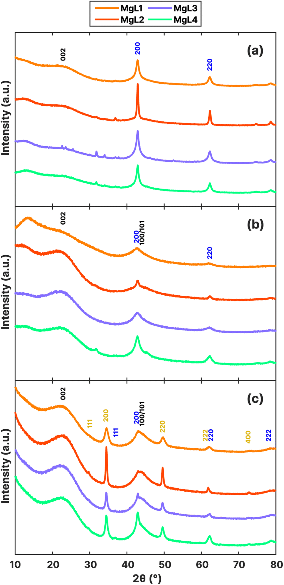 | ||
| Fig. 7 XRD patterns of MgL-derived carbons: (a) pre-washed, (b) acid-washed, and (c) HT-carbon. The black, blue, and yellow annotations indicate the presence of graphitic carbon, MgO, and MgS crystalline structures, respectively. | ||
MgS is a major by-product obtained from the MgL-HT carbons, with peaks observed at 29.8°, 34.5°, 49.6°, 61.9°, and 72.9°, corresponding to the (111), (200), (220), (222), and (400) planes, respectively. A significant amount of sulfur came from MgSO4 during precipitation, as inferred from the sulfur content progression in Table 3. Starting at 350 °C, the transformation of sulfur was driven by thermochemical reduction of MgSO4 and aromatization. The thermochemical reduction of MgSO4 by organic compounds generates MgO, H2S, and CO2, during which thiophenes are also increasingly produced both in the solid and tar phases.77,78 At temperatures above 700 °C (during the MgL-HT carbonization process), a sharp degradation of these thiophene compounds occurs, leading to significant H2S formation. As pyrolysis progressed, these H2S chemisorbs on the MgO surface, which has a high affinity for H2S.79,80 Since MgO is a basic oxide and H2S is a weak acid, they would undergo an acid–base neutralization reaction following the mechanism given below.
| MgO + H2S → MgS + H2O | (5) |
The interlayer spaces between graphene layers (d002), the apparent crystallite thickness along the c-axis (Lc), and the apparent crystallite width along the a-axis (La) were calculated for MgL-HT carbons, and the results are presented in Table 4. The d002 values ranged from 3.82 to 3.86 Å, which is greater than 3.70 Å, proposed by Cao et al.81 as the distance needed for sodium ions to overcome the energy barrier and intercalate between the graphene layers when the carbon is used as the anode material for sodium-ion batteries. Meanwhile, the Lc and La of the MgL-HT carbons did not differ from each other considerably, indicating consistent crystallite sizes of the graphitic domains across all synthesis methods.
| Sample | From XRD | From Raman | ||||
|---|---|---|---|---|---|---|
| d002 (Å) | Lc (Å) | La (Å) | AD1/AG | AD1/(AG + AD1 + AD2) | FWHM of D1 peak (cm−1) | |
| MgL1-HT | 3.84 | 10.8 | 48.2 | 3.11 | 0.740 | 117 |
| MgL2-HT | 3.84 | 10.5 | 46.3 | 3.58 | 0.758 | 117 |
| MgL3-HT | 3.86 | 10.4 | 46.6 | 3.13 | 0.741 | 108 |
| MgL4-HT | 3.82 | 10.7 | 49.2 | 2.98 | 0.731 | 118 |
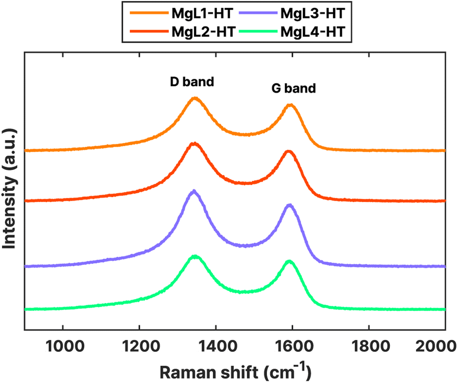
Nanoscale structures and the degree of disorder in MgL-HT carbons were further investigated using Raman spectroscopy. The obtained Raman spectra, shown in Fig. 8, exhibited characteristic peaks typical for carbonaceous materials at around 1350 cm−1 (D band) and 1600 cm−1 (G band). The G band signifies the ideal graphitic lattice, whereas the D band indicates defects within the lattice structure, or the presence of amorphous characteristics in the carbon. From the acquired spectra, the D band is slightly higher than the G band. The ratio of intensities (ID/IG) between these bands could serve as a quantitative measure of structural disorder in the carbon. To quantify this ratio, a preliminary procedure was performed, wherein the G and D bands in the Raman spectra were deconvoluted into four Lorentzian-shaped bands (G, D1, D2, and D4) and one Gaussian-shaped band (D3). A peak area ratio such as AD1/AG can then be calculated as ID/IG.39,82 Other indicators, such as the AD1/(AG + AD1 + AD2) ratio and the full width at half-maximum (FWHM) of the D1 peak, were also suggested to lessen the variability induced by analytical and fitting procedures and to serve as a robust indicator of structural ordering of the carbonaceous material, respectively.39,83
 | ||
| Fig. 8 Raman spectra of MgL-HT carbons. | ||
The deconvolution of the obtained Raman peaks is shown in Fig. S4,† while the calculated structural disorder indicators are presented in Table 4. Higher AD1/AG and AD1/(AG + AD1 + AD2) ratios and higher FWHMs of the D1 peak suggest a larger structural disorder. As can be seen from Table 4, these values for MgL2-HT are the highest. This disorder could have stemmed from the higher heterogeneity (polydispersity) of its initial lignin fraction, likely leading to a more disordered structure upon carbonization. The other three samples which underwent magnesium fractionation had lower values, indicating relatively more ordered structures.
The textural features of the materials after carbonization and template removal were determined through N2 adsorption, as summarized in Fig. 9 and Table 5. All the carbons exhibited type I isotherms, distinguished by their steep uptake at low relative pressure (P/P0) values due to enhanced adsorbent–adsorptive interactions in narrow micropores (Fig. 9a). Specifically, type I (a) isotherms are observed for MgL1, MgL2, and MgL4, mainly having pores with widths narrower than approximately 1 nm. MgL3, on the other hand, showed characteristics of type I (b) isotherm, with pore size distributions that include wider micropores to narrow mesopores.84 These findings are corroborated by the pore size distribution graph obtained using the QSDFT model.
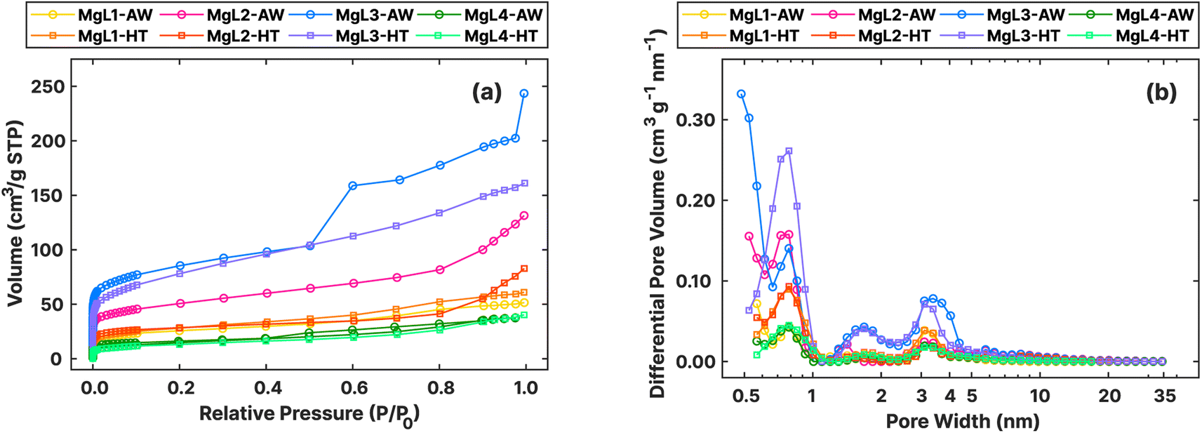 | ||
| Fig. 9 (a) Adsorption isotherms of N2 at −196 °C obtained for MgL-AW and MgL-HT carbons. (b) Pore size distributions from N2 adsorption isotherms, assessed using the QSDFT model, for MgL-AW and MgL-HT carbons. | ||
| Sample | SABET (m2 g−1) | Avg. pore size (nm) | Pore vol. (cm3 g−1) |
|---|---|---|---|
| MgL1-AW | 94 | 3.4 | 0.080 |
| MgL2-AW | 183 | 4.4 | 0.203 |
| MgL3-AW | 310 | 4.9 | 0.377 |
| MgL4-AW | 53 | 2.2 | 0.058 |
| MgL1-HT | 103 | 3.6 | 0.094 |
| MgL2-HT | 105 | 4.8 | 0.128 |
| MgL3-HT | 278 | 3.6 | 0.249 |
| MgL4-HT | 50 | 5.0 | 0.062 |
As shown in Fig. 9b, the pore distribution of all carbon was found to be more concentrated at widths below 1 nm. The dropwise addition of Mg2+ likely allowed relatively isolated interaction with oxygen groups at various sites, resulting in MgO crystal domains that yielded smaller than 1 nm pores after removal. Meanwhile, MgL3 exhibited a higher presence of mesopores, whose formation strongly depends on the type of MgO precursor used.33 This may again be attributed to the high pH during fractionation and complex formation, which made Mg(OH)2 common in the matrix, leading to the formation of larger MgO crystal domains, as compared to Mg2+. This convenient tunability of pore sizes through changes in fractionation pH enables the creation of carbons with diverse porosity. Additionally, MgL-AW carbons seemed to exhibit more pores as the widths become lower below 0.5 nm, with their distribution curves trending upward beyond the measurement limits. The possible abundance of pores smaller than 0.5 nm in MgL-AW carbons and their absence in MgL-HT carbons aligned with the expected outcome of applying higher carbonization temperatures. Higher temperatures lead to enhanced degree of graphitization and the gradual collapse and closure of existing pores, starting with the smallest ones.85
TEM images of MgL-HT carbons, which provide valuable information on the final pore structures, are shown in Fig. 10. A bimodal hierarchical porosity, which features interconnection of the pores at micro-/meso-length scales, can be observed in all MgL-HT carbons. This is likely due to the formation of interconnected MgO crystals of varying sizes, resulting from the presence of different magnesium precursors in the MgL complex, driven by pH-influenced magnesium–lignin interactions. This is favorable as it can facilitate ion transfers at the electrode/electrolyte interface for energy storage applications, enhance reagent diffusion during catalytic reactions, and its increased permeability also makes it a potential adsorbent for gas and liquid separation.86
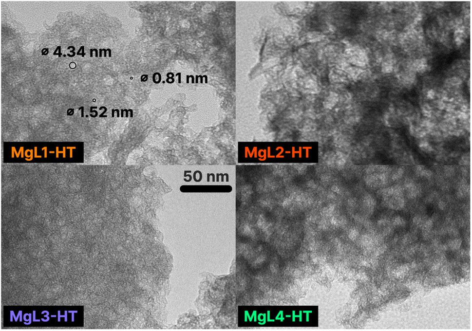 | ||
| Fig. 10 TEM images of MgL-HT carbons. Magnification: 120k×. The displayed 50 nm scale is applicable to all images. Some pore diameters are specified in MgL1-HT. | ||
3.4 Prospects of MgL-derived carbons
The integrated, stoichiometrically driven fractionation and templating method, using magnesium to produce high-value carbon from lignin, aligns with UN SDG 12 by promoting sustainable consumption and production. This approach also offers a safer and more environmentally friendly alternative to traditional acid- and organic-based fractionation techniques, which pose significant environmental and safety risks. In addition, the lignin fractions utilized in this study are the ones bound to magnesium, as they produce higher yields. However, the discarded supernatant after fractionation, although smaller in amount, could also find use in producing other higher value-added lignin-based materials, such as lignin nanoparticles, with its expected lower molecular weight and polydispersity.87,88 During pore formation, Mg2+ ions can also be recovered from the acid washing process and reused, enhancing the sustainability of the technique.MgL-AW and MgL-HT carbons, with their porous and graphitic structure, have shown potential for use in supercapacitors and alkali-ion batteries, similar to previously studied MgO-templated carbons.34,89 Moreover, MgL-HT carbons are MgS/C composites, the same material that Helen and Fichtner90 utilized as an anode material for a lithium-ion battery, achieving a stable capacity of 530 mA h g−1 after 100 cycles. This composite leveraged the MgS theoretical capacity of 951 mA h g−1 with lithium, and an analogous system is theoretically possible with sodium. MgL-PW, with its MgO/C structure, can be used as a catalyst in the production of aromatic hydrocarbon from lignin. In fact, among the catalysts tested by Ryu et al.,91 the MgO/C structured one was the most efficient in removing oxygenated compounds, thereby enhancing the production of aromatic hydrocarbons. The MgO in MgL-PW can likewise be utilized for hydrogen sulfide removal,80 while MgL-HT, again with its MgS/C structure, is effective for the removal of heavy metals from industrial effluents.92
When synthesizing carbon for various applications, information about yields is often scarce, with studies featuring complicated and multi-step processes without fully considering the practicality or quantities of chemicals involved.4,93 So, even though the resulting material is the most novel material and has the best performance among the state-of-the-art ones, upscaling the process becomes a huge challenge. The yields of the carbon produced with the simple technique presented in this work are high enough and well accounted for in Table S1.† Sharma et al.94 pyrolyzed lignin up to 750 °C, and the yield was around 40% solid char. The same amount can also be estimated from TGA curves of SKL in Fig. 3. Meanwhile, the MgL-HT carbons achieved yields of around 37% to 49%, based on the initial lignin weight (Table S1†), even after subjecting them to temperatures as high as 1400 °C. Additionally, the used MgO porogen is much more environment-friendly than the usually employed KOH, which has a detrimental impact on the environment and, incidentally, results in a low carbon yield.95 Upscaling the process developed in this work is therefore economical, as well as ecological due to the absence of environmentally adverse chemicals, as earlier mentioned.
Two downsides of the technique, however, are that high temperatures are still required to produce the carbon materials, and additional acid washing steps are necessary to remove the template or to isolate the lignin after fractionation. While the use of higher temperatures is harder to circumvent at this stage, sustainability can be improved by potentially eliminating or reducing the acid washing step. This can be the case if higher ratios of MgO or MgS are desired in the final product.
4 Conclusions
This study evaluated a lignin fractionation method that uses magnesium ions (Mg2+) to precipitate with lignin and form MgL complexes. This process was combined with a MgO templating technique to produce porous carbon. Potential mechanisms involving magnesium–lignin interactions at distinct pH ranges were presented to elucidate how the resulting lignin fractions in MgL complexes varied in chemical structure, molecular weight distribution and polydispersity. MgL complexes fractionated at a high pH generally showed HMW fractions, with lower heterogeneity and polydispersity compared to their lignin precursor. The same interactions were also linked to the optimized yield of MgL complex-derived carbon, as they inhibited certain pyrolysis reactions, such as the cleavage of ether linkages. Insight into the sudden formation of magnesium sulfide (MgS) after the second stage carbonization was also provided, wherein the thermochemical reduction of sulfate and the degradation of thiophene compounds were identified as the main drivers. Additionally, pore formation facilitated by MgO templating was found to be tunable by adjusting the MgO crystal formation through the fractionation pH. Hierarchical bimodal micro-/mesopore size distributions, resulting from the pH-influenced magnesium–lignin interactions, were also achieved in the MgL-HT carbons. Altogether, these findings lay a strong foundation for future research, including the exploration of alternative anions and precipitating agents to MgSO4, a deeper investigation of the roles of Mg and S in specific applications such as energy storage, catalysis, adsorption, and filtration, and the advancement of these materials for use as hard carbon. Finally, this work highlights the potential for generating various functionalities in the synthesized materials through each step of the process, from the initial fractionation and precipitation to the formation of the complex and its subsequent transformations into MgL-PW, MgL-AW, and MgL-HT.Data availability
The data supporting this article have been included as part of the ESI.† The RAMAN-Deconvolution code used in this study is available at GitHub (https://github.com/MacDumi/RAMAN-Deconvolution).40 The version employed is v1.0.2β (commit SHA: 8c8ac0a0da544823530df70d50631d89901afb63).Author contributions
Angelo Robiños: conceptualization, writing – original draft, methodology, investigation, formal analysis, visualization, data curation, and funding acquisition. Hao Zhang: investigation, formal analysis, writing – review & editing, and funding acquisition. Zekra Mousavi: supervision and writing – review & editing. Tor Laurén: resources and project administration. Jan-Henrik Smått: investigation, formal analysis, and writing – review & editing. Leena Hupa: supervision, writing – review & editing. Chunlin Xu: supervision, writing – review & editing, project administration, resources, and funding acquisition, Johan Bobacka: supervision, writing – review & editing, project administration, resources, and funding acquisition.Conflicts of interest
There are no conflicts to declare.Acknowledgements
A. R. would like to thank the Åbo Akademi Doctoral Study Network for the financial support. All the authors would like to thank the Jane and Aatos Erkko Foundation for funding the “Development of sustainable technologies for electrical energy storage based on biomaterials and 3D printing project (SUSTEC, Grant no. 220015)” to which this research belongs to. This work is part of the activities of the Johan Gadolin Process Chemistry Centre (PCC). Parts of the research used the Research Council of Finland Research Infrastructure “Printed Intelligence Infrastructure” (PII-FIRI). M. J. Dirbeba is gratefully acknowledged for providing assistance in drafting the mass flowchart.Notes and references
- W.-J. Liu, H. Jiang and H.-Q. Yu, Chem. Rev., 2015, 115, 12251–12285 CrossRef CAS PubMed.
- F. Lian and B. Xing, Environ. Sci. Technol., 2017, 51, 13517–13532 CrossRef CAS.
- S. Khodabakhshi, P. F. Fulvio and E. Andreoli, Carbon, 2020, 162, 604–649 CrossRef CAS.
- W. Zhang, X. Qiu, C. Wang, L. Zhong, F. Fu, J. Zhu, Z. Zhang, Y. Qin, D. Yang and C. C. Xu, Carbon Res., 2022, 1, 14 CrossRef CAS.
- H. Marsh and F. Rodriguez-Reinoso, Activated Carbon, 2006, pp. 243–321 Search PubMed.
- E. Lizundia, M. H. Sipponen, L. G. Greca, M. Balakshin, B. L. Tardy, O. J. Rojas and D. Puglia, Green Chem., 2021, 23, 6698–6760 RSC.
- X. Lin, Y. Liu, H. Tan and B. Zhang, Carbon, 2020, 157, 316–323 CrossRef CAS.
- J. S. Yeon, S. H. Park, J. Suk, H. Lee and H. S. Park, Chem. Eng. J., 2020, 382, 122946 CrossRef CAS.
- W. Li, G. Wang, W. Sui, Y. Xu, A. M. Parvez and C. Si, Int. J. Biol. Macromol., 2023, 234, 123603 CrossRef CAS PubMed.
- M. Xu, X. Zhu, Y. Lai, A. Xia, Y. Huang, X. Zhu and Q. Liao, Appl. Energy, 2024, 353, 122095 CrossRef CAS.
- W. Li, C. Li, Y. Xu, G. Wang, T. Xu, W. Zhang and C. Si, J. Colloid Interface Sci., 2024, 659, 374–384 CrossRef CAS.
- X. Yu, L. Peng, X. Gao, L. He and K. Chen, RSC Adv., 2018, 8, 15762–15772 RSC.
- M. Li, Q. Zhang, B. Luo, C. Chen, S. Wang and D. Min, Ind. Crops Prod., 2020, 145, 111920 CrossRef CAS.
- Y. Qi, J. Li, Y. Zhang, Q. Cao, Y. Si, Z. Wu, M. Akram and X. Xu, Appl. Catal., B, 2021, 286, 119910 CrossRef CAS.
- L. Sellaoui, A. Gómez-Avilés, F. Dhaouadi, J. Bedia, A. Bonilla-Petriciolet, S. Rtimi and C. Belver, Chem. Eng. J., 2023, 452, 139399 CrossRef CAS.
- G.-J. Jiao, J. Ma, Y. Li, D. Jin, Y. Guo, J. Zhou and R. Sun, Sci. Total Environ., 2021, 761, 143217 CrossRef CAS.
- T. Pang, G. Wang, H. Sun, W. Sui and C. Si, Ind. Crops Prod., 2021, 165, 113442 CrossRef CAS.
- W. Li, G. Wang, W. Sui, T. Xu, L. Dai and C. Si, Ind. Crops Prod., 2023, 204, 117276 CrossRef CAS.
- K.-L. Wu, W.-W. Zhang, T.-B. Jiang, M. Wu, W. Liu, H.-M. Wang and Q.-X. Hou, Int. J. Biol. Macromol., 2023, 227, 146–157 CrossRef CAS.
- Q. Li, S. Xie, W. K. Serem, M. T. Naik, L. Liu and J. S. Yuan, Green Chem., 2017, 19, 1628–1634 Search PubMed.
- Z. Xue, H. Sun, G. Wang, W. Sui, H. Jia and C. Si, Int. J. Biol. Macromol., 2024, 258, 128963 CrossRef CAS.
- A.-S. Jääskeläinen, T. Liitiä, A. Mikkelson and T. Tamminen, Ind. Crops Prod., 2017, 103, 51–58 CrossRef.
- Q. Yan, J. Li, X. Zhang, E. B. Hassan, C. Wang, J. Zhang and Z. Cai, J. Nanopart. Res., 2018, 20, 1–20 CrossRef CAS.
- H. Zhou, S. Hong, H. Zhang, Y. Chen, H. Xu, X. Wang, Z. Jiang, S. Chen and Y. Liu, Appl. Catal., B, 2019, 256, 117767 CrossRef.
- N. Ponomarev, O. Pastushok, E. Repo, B. Doshi and M. Sillanpaa, ACS Appl. Nano Mater., 2019, 2, 5492–5503 CrossRef CAS.
- K. Dai, X. Peng, P. Yang, M. Li, C. Tang, W. Zhuang, H. Ying and J. Wu, J. Environ. Chem. Eng., 2020, 8, 104283 CrossRef CAS.
- R. Kaur, S. Sandhu, A. K. Pujari, S. Paul and J. Bhaumik, ChemistrySelect, 2024, 9, e202402934 CrossRef CAS.
- E. I. Evstigneyev, E. V. Grinenko, A. S. Mazur and A. V. Vasilyev, J. Wood Chem. Technol., 2021, 41, 73–82 CrossRef CAS.
- J. Sundin and N. Hartler, Nord. Pulp Pap. Res. J., 2000, 15, 306–312 CAS.
- R. Garcia-Valls and T. Hatton, Chem. Eng. J., 2003, 94, 99–105 CrossRef CAS.
- E. Melro, A. Filipe, D. Sousa, A. J. Valente, A. Romano, F. E. Antunes and B. Medronho, Int. J. Biol. Macromol., 2020, 148, 688–695 CrossRef CAS.
- T. Lindström, Colloid Polym. Sci., 1980, 258, 168–173 CrossRef.
- T. Morishita, T. Tsumura, M. Toyoda, J. Przepiórski, A. Morawski, H. Konno and M. Inagaki, Carbon, 2010, 48, 2690–2707 CrossRef CAS.
- A. Kamiyama, K. Kubota, D. Igarashi, Y. Youn, Y. Tateyama, H. Ando, K. Gotoh and S. Komaba, Angew. Chem., Int. Ed., 2021, 60, 5114–5120 CrossRef CAS.
- W. Geng, F. Ma, G. Wu, S. Song, J. Wan and D. Ma, Electrochim. Acta, 2016, 191, 854–863 CrossRef CAS.
- P. Tomani, Cellul. Chem. Technol., 2010, 44, 53 CAS.
- X. Meng, C. Crestini, H. Ben, N. Hao, Y. Pu, A. J. Ragauskas and D. S. Argyropoulos, Nat. Protoc., 2019, 14, 2627–2647 CrossRef CAS PubMed.
- G. Zinovyev, I. Sulaeva, S. Podzimek, D. Rössner, I. Kilpeläinen, I. Sumerskii, T. Rosenau and A. Potthast, ChemSusChem, 2018, 11, 3259–3268 CrossRef CAS PubMed.
- A. Sadezky, H. Muckenhuber, H. Grothe, R. Niessner and U. Pöschl, Carbon, 2005, 43, 1731–1742 CrossRef CAS.
- D. Duca and T. Vranken, Deconvolution of Raman spectra, https://github.com/MacDumi/RAMAN-Deconvolution, 2021.
- S. Brunauer, P. H. Emmett and E. Teller, J. Am. Chem. Soc., 1938, 60, 309–319 CrossRef CAS.
- A. V. Neimark, Y. Lin, P. I. Ravikovitch and M. Thommes, Carbon, 2009, 47, 1617–1628 CrossRef CAS.
- H. Sadeghifar and A. Ragauskas, ACS Sustainable Chem. Eng., 2020, 8, 8086–8101 Search PubMed.
- M. Ragnar, C. T. Lindgren and N.-O. Nilvebrant, J. Wood Chem. Technol., 2000, 20, 277–305 CrossRef CAS.
- H. L. Hergert, J. Org. Chem., 1960, 25, 405–413 CrossRef CAS.
- O. Faix, Holzforschung, 1991, 45, 21–28 CrossRef CAS.
- P. Bock, P. Nousiainen, T. Elder, M. Blaukopf, H. Amer, R. Zirbs, A. Potthast and N. Gierlinger, J. Raman Spectrosc., 2020, 51, 422–431 CrossRef CAS.
- R. Buchanan, H. Caspers and J. Murphy, Appl. Opt., 1963, 2, 1147–1150 CrossRef CAS.
- E. Piperopoulos, M. Fazio, E. Mastronardo, M. Lanza and C. Milone, Materials, 2021, 14, 1091 CrossRef CAS PubMed.
- W. Zhu, G. Westman and H. Theliander, Nord. Pulp Pap. Res. J., 2016, 31, 270–278 CrossRef CAS.
- D. Elalami and A. Barakat, Clean Energy and Resources Recovery, Elsevier, 2021, pp. 1–24 Search PubMed.
- Z. Guangyin and Z. Youcai, Pollution Control and Resource Recovery for Sewage Sludge, 2017, vol. 4, pp. 181–273 Search PubMed.
- S. Sarkanen, D. C. Teller, C. R. Stevens and J. L. McCarthy, Macromolecules, 1984, 17, 2588–2597 CrossRef CAS.
- L. Ji, L.-Y. Liu, M. Cho, M. A. Karaaslan and S. Renneckar, Biomacromolecules, 2021, 23, 708–719 CrossRef.
- D. Guo, S. Wu, G. Lyu and H. Guo, Fuel, 2017, 193, 45–53 CrossRef CAS.
- K. Wang, F. Xu and R. Sun, Int. J. Mol. Sci., 2010, 11, 2988–3001 CrossRef CAS PubMed.
- X. Cao, L. Shao, W. Huang, C. Wang, J. Mao, F. Xu and X. Zhang, J. Anal. Appl. Pyrolysis, 2021, 157, 105200 CrossRef CAS.
- Z. Wu, J. Zou, Y. Zhang, X. Lin, D. Fry, L. Wang and J. Liu, Chem. Eng. J., 2022, 427, 131547 CrossRef CAS.
- Q. Li, W. K. Serem, W. Dai, Y. Yue, M. T. Naik, S. Xie, P. Karki, L. Liu, H.-J. Sue and H. Liang, et al., J. Mater. Chem. A, 2017, 5, 12740–12746 RSC.
- W. Chen, Y. Zong, Y. Zhou, W. Lu, Y. Zhang and J. Qian, Colloids Surf., A, 2019, 571, 160–167 CrossRef CAS.
- M. Kitagawa, S. Misu, J. Ichikawa and H. Matsuhashi, Res. Chem. Intermed., 2015, 41, 9463–9473 CrossRef CAS.
- F.-X. Collard and J. Blin, Renewable Sustainable Energy Rev., 2014, 38, 594–608 CrossRef CAS.
- H. Kawamoto, S. Horigoshi and S. Saka, J. Wood Sci., 2007, 53, 168–174 CrossRef CAS.
- T. Nakamura, H. Kawamoto and S. Saka, J. Anal. Appl. Pyrolysis, 2008, 81, 173–182 CrossRef CAS.
- J. F. Haw and T. P. Schultz, Holzforschung, 1985, 39, 289–296 CrossRef CAS.
- Y. Pu, D. Zhang, P. M. Singh and A. J. Ragauskas, Biofuels, Bioproducts and Biorefining: Innovation for a Sustainable Economy, 2008, vol. 2, pp. 58–73 Search PubMed.
- H. Kawamoto, J. Wood Sci., 2017, 63, 117–132 CrossRef CAS.
- H. Kawamoto, M. Ryoritani and S. Saka, J. Anal. Appl. Pyrolysis, 2008, 81, 88–94 CrossRef CAS.
- D. A. Skoog, F. J. Holler and S. R. Crouch, Instrumental Analysis, Brooks/Cole, Cengage Learning Belmont, 2007, vol. 47 Search PubMed.
- Q. Liu, S. Wang, Y. Zheng, Z. Luo and K. Cen, J. Anal. Appl. Pyrolysis, 2008, 82, 170–177 CrossRef CAS.
- S. D. Stefanidis, S. Karakoulia, K. G. Kalogiannis, E. Iliopoulou, A. Delimitis, H. Yiannoulakis, T. Zampetakis, A. Lappas and K. Triantafyllidis, Appl. Catal., B, 2016, 196, 155–173 CrossRef CAS.
- M. Zhang, Y. Li, F. Wu, Y. Bai and C. Wu, Nano Energy, 2021, 82, 105738 CrossRef CAS.
- S. Alvin, D. Yoon, C. Chandra, R. F. Susanti, W. Chang, C. Ryu and J. Kim, J. Power Sources, 2019, 430, 157–168 CrossRef CAS.
- S. Veldurthi, C.-H. Shin, O.-S. Joo and K.-D. Jung, Microporous Mesoporous Mater., 2012, 152, 31–36 CrossRef CAS.
- T. Zhang, J. Mao, X. Liu, M. Xuan, K. Bi, X. L. Zhang, J. Hu, J. Fan, S. Chen and G. Shao, RSC Adv., 2017, 7, 41504–41511 Search PubMed.
- X. Dou, I. Hasa, D. Saurel, C. Vaalma, L. Wu, D. Buchholz, D. Bresser, S. Komaba and S. Passerini, Mater. Today, 2019, 23, 87–104 CrossRef CAS.
- R. Huang, Y. Tang and L. Luo, Waste Manage., 2021, 121, 276–285 CrossRef CAS PubMed.
- K. Ding, S. Wang, S. Li and C. Yue, Geochem. J., 2011, 45, 97–108 CrossRef CAS.
- J. Zhang, W. Zuo, Y. Tian, L. Chen, L. Yin and J. Zhang, Environ. Sci. Technol., 2017, 51, 709–717 CrossRef CAS PubMed.
- J. A. Rodriguez and A. Maiti, J. Phys. Chem. B, 2000, 104, 3630–3638 CrossRef CAS.
- Y. Cao, L. Xiao, M. L. Sushko, W. Wang, B. Schwenzer, J. Xiao, Z. Nie, L. V. Saraf, Z. Yang and J. Liu, Nano Lett., 2012, 12, 3783–3787 CrossRef CAS.
- D. Alvira, D. Antorán and J. J. Manyà, J. Energy Chem., 2022, 75, 457–477 Search PubMed.
- O. Beyssac, B. Goffé, J.-P. Petitet, E. Froigneux, M. Moreau and J.-N. Rouzaud, Spectrochim. Acta, Part A, 2003, 59, 2267–2276 CrossRef.
- M. Thommes, K. Kaneko, A. V. Neimark, J. P. Olivier, F. Rodriguez-Reinoso, J. Rouquerol and K. S. Sing, Pure Appl. Chem., 2015, 87, 1051–1069 CrossRef CAS.
- B. Zhang, C. M. Ghimbeu, C. Laberty, C. Vix-Guterl and J.-M. Tarascon, Adv. Energy Mater., 2016, 6, 1501588 CrossRef.
- M.-H. Sun, S.-Z. Huang, L.-H. Chen, Y. Li, X.-Y. Yang, Z.-Y. Yuan and B.-L. Su, Chem. Soc. Rev., 2016, 45, 3479–3563 RSC.
- H. Sun, G. Wang, J. Ge, N. Wei, W. Sui, Z. Chen, H. Jia, A. M. Parvez and C. Si, Ind. Crops Prod., 2022, 180, 114685 CrossRef CAS.
- I. V. Pylypchuk, M. Karlsson, P. A. Lindén, M. E. Lindström, T. Elder, O. Sevastyanova and M. Lawoko, Green Chem., 2023, 25, 4415–4428 RSC.
- Y. Kado and Y. Soneda, J. Phys. Chem. Solids, 2016, 99, 167–172 CrossRef CAS.
- M. Helen and M. Fichtner, Electrochim. Acta, 2015, 169, 180–185 CrossRef.
- H. W. Ryu, H. W. Lee, J. Jae and Y.-K. Park, Energy, 2019, 179, 669–675 CrossRef CAS.
- N. Sankararamakrishnan, R. Singh and I. Srivastava, Sci. Rep., 2019, 9, 12639 CrossRef PubMed.
- W. Shao, H. Shi, X. Jian, Z.-S. Wu and F. Hu, Adv. Energy Sustainability Res., 2022, 3, 2200009 CrossRef CAS.
- R. K. Sharma, J. B. Wooten, V. L. Baliga, X. Lin, W. G. Chan and M. R. Hajaligol, Fuel, 2004, 83, 1469–1482 CrossRef CAS.
- N. A. Rashidi and S. Yusup, Chem. Eng. J., 2017, 314, 277–290 CrossRef CAS.
Footnote |
| † Electronic supplementary information (ESI) available. See DOI: https://doi.org/10.1039/d5su00256g |
| This journal is © The Royal Society of Chemistry 2025 |