Synchronous dual additives to boost multiphase interface stability of high-voltage Li-rich Mn-based batteries†
Qiangfeng
Zhang
,
Shijie
Xu
,
Haipeng
Zhu
,
Zhao
Chen
,
Libao
Chen
 ,
Chunxiao
Zhang
 * and
Weifeng
Wei

State Key Laboratory of Powder Metallurgy, Central South University, Changsha, Hunan 410083, P. R. China. E-mail: chunxiaozhang@csu.edu.cn
First published on 25th November 2024
Abstract
High-voltage lithium-rich manganese-based oxides (LRMOs) are expected to become next-generation mainstream cathodes due to their higher voltage, higher specific capacity and lower cost. However, currently commercialized carbonate electrolytes still face the challenge of poor decomposition of solvents and lithium salts at high voltage, leading to serious interface side reactions and electrochemical performance degradation. Herein, we propose an interfacial chemical modification strategy based on the dual additives of fluoroethylene carbonate (FEC) and tris(trimethylsilyl)phosphate (TMSPa), to promote Li+ migration and ensure long-term cycling stability of LRMO-based batteries. Detailed characterization reveals that the dual additives FEC-TMSPa can promote the desolvation process of Li+ and reduce the adverse decomposition of electrolyte components by regulating the solvation structure of the electrolyte. Simultaneously, dual additives can facilitate the formation of a robust cathode electrolyte interphase (CEI)/solid electrolyte interphase (SEI) rich-in F/P/Si species, thereby reducing the interface side reactions, inhibiting the erosion of acidic substances on electrodes, and promoting the uniform deposition/stripping of Li+. As a result, the high-voltage LRMO-based batteries exhibit excellent rate performance and cycling stability, with a capacity retention of 82.36% after 500 cycles at 30 °C, and 86.9% after 150 cycles at a high-temperature of 55 °C, suggesting that the proposed strategy of synergistically regulating the interface chemistry with multiple additives is anticipated to facilitate the further application of high-voltage layered cathode materials.
1 Introduction
The rapid development of portable electronic products as well as new energy vehicles has led to an increasing demand for batteries with high energy density.1–4 And a series of high-capacity electrode materials have been systematically investigated to meet the urgent needs in modern society. Among numerous candidates, lithium-rich manganese-based oxides (LRMO) emerge as a promising competitor for next-generation cathodes owing to their high voltage (>4.6 V), high theoretical specific capacity (>250 mA h g−1), and low cost.5–13 As for anode materials, lithium metal anodes, with a low electrochemical potential (−3.04 V vs. the standard hydrogen electrode, SHE), ultra-high theoretical specific capacity (3860 mA h g−1), and low mass density (0.534 g cm−3), are considered as the “holy grail” electrodes, and embody absolute superiority in enhancing energy density.14–18 Unfortunately, LRMOs encounter serious challenges including the irreversible release of lattice oxygen and structural transformation.19–23 Moreover, they will suffer from severe performance degradation when applied in conjunction with ethylene carbonate (EC) based electrolytes at high voltage (>4.6 V).24 Specifically, EC will be oxidized and undergo dehydrogenation reactions at high voltage (>4.5 V), resulting in the production of electrochemically inert by-products like COx gas and ROCO2Li.2 Meanwhile, the poor decomposition of LiPF6 will also induce the formation of by-products such as acidic substances, HF, and LixPFyOz,25 in which, LixPFyOz will participate in the formation of a cathode electrolyte interphase (CEI)/solid electrolyte interphase (SEI) together with solvent-derived by-products.26–28 The organic species dominated CEI/SEI are easily eroded by HF and dissolved into the electrolyte, and then rebuilt during the cycle, leading to the uneven distribution of the CEI/SEI and accelerating interface reactions and structural transformation of the cathodes.29–31 Similarly, the carbonate-based electrolyte will also undergo severe side reactions with the Li metal anode, thereby inducing dendrite growth, dead lithium evolution, and the formation of a heterogeneous SEI.32–35 Therefore, it is crucial to develop an electrolyte that is compatible with high-voltage Li-rich cathodes and Li metal anodes.36Up to now, various strategies have been explored to address the challenge of extreme instability of carbonate-based electrolytes at high voltage, including the introduction of fluorinated solvents, nitrile solvents, and sulfone solvents, and construction of high-concentration electrolytes.37 Although these strategies have been proven to enhance the oxidative stability of electrolytes at high voltage, their high cost, limited lithium salt dissociation, and high viscosity still impede their practical implementation. In contrast, the additive strategy is more flexible and economical. Previous studies have confirmed that phosphate or phosphite organic compounds are more easily oxidized than solvent molecules, and can preferentially decompose to form a stable CEI on the surface of cathodes.38 Additionally, the incorporation of fluorine-containing additives can induce the formation of a robust SEI to promote uniform deposition/stripping of Li+ and inhibit the growth of lithium dendrites at the anode side.39 Therefore, constructing a stable CEI/SEI through the synergistic effect of multiple functional additives is expected to effectively improve the electrochemical performance of batteries.
In this work, we introduce functional additives containing F (FEC) and P/Si (TMSPa) into a commercial LiPF6-based carbonate electrolyte to construct stable multiphase interfaces. Theoretical calculations and experimental results demonstrate that the additive synergistic strategy can effectively regulate the solvation structure of electrolytes to promote the desolvation process of Li+ and enhance the electrochemical kinetics. Moreover, it can inhibit the poor decomposition of electrolyte components and construct a stable and robust CEI/SEI, significantly suppressing structural degradation during cycling and promoting uniform deposition/stripping of Li+ (Scheme 1). As a result, the high-voltage LRMO-based cells with dual additives exhibit excellent rate performance and high-temperature cycle stability.
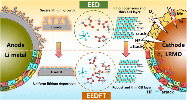 | ||
| Scheme 1 Working mechanism of the as-proposed dual-additive formulation for regulating the electrode/electrolyte interfaces in a LRMO‖Li battery system. | ||
2 Results and discussion
2.1 Solvation structure of the electrolytes
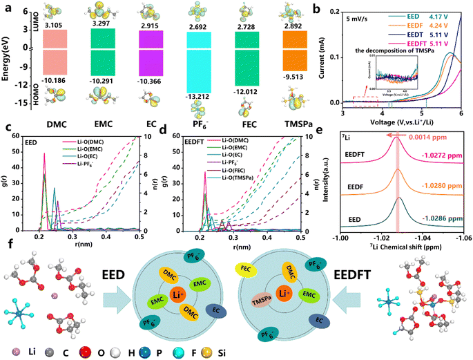
The components of the electrolytes in this work can be found in the ESI,† and the bare electrolyte (LiPF6-EC/EMCDMC) is labeled as EED. Similarly, electrolytes with FEC, TMSPa and FEC-TMSPa introduced are denoted as EEDF, EEDT and EEDFT respectively.First, the redox ability of the electrolyte components was analyzed by theoretical calculation. The lowest unoccupied molecular orbital (LUMO) and highest occupied molecular orbital (HOMO) values of EC, EMC, DMC, FEC, TMSPa, and PF6− are shown in Fig. 1a. The results indicate that TMSPa, FEC, and PF6− species exhibit lower LUMO values, representing the tendency of reduction on the anode side to form a SEI. Meanwhile, TMSPa shows a higher HOMO value than the solvent molecules and PF6−, indicating that TMSPa tends to preferentially oxidize and decompose to form a CEI on the cathode surface during the charging process. This is also confirmed by the linear sweep voltammetry (LSV) test, as shown in Fig. 1b and S1;† the EEDFT electrolyte exhibits a significant increase in oxidation current between 3.5 and 4.0 V, corresponding to the early oxidation decomposition of TMSPa. However, under the synergistic effect of FEC and TMSPa, the electrochemical window of the electrolyte expands from 4.2 V to 5.11 V.
The solvation structure of Li+ in the electrolyte was investigated through Molecular Dynamics (MD) simulations (Fig. S2†). Fig. 1c and d and Table S1† illustrate the radial distribution functions (RDF, g(r)) and coordination numbers (n(r)) of various components in the electrolytes. The results show that TMSPa and FEC additives can enter the first and second solvation shell of Li+, respectively, and reduce the coordination number of Li+-solvent molecules, thus effectively promoting the desolvation process of Li+ and the formation of a stable interphase. Simultaneously, the RDFs show that the distance between Li+ and PF6− increases after the introduction of additives, indicating a decrease in the interaction between Li+ and PF6−, which can reduce the interface reaction caused by the adverse decomposition of anions. The corresponding nuclear magnetic resonance (NMR) spectra show that the introduction of dual additives leads to a downshift in the 7Li peak, indicating a reduction in the electronic shielding effect and a weaker electronegative environment surrounding Li+ in EEDFT, which consequently promotes the desolvation process of Li+ and facilitates the reduction of interfacial impedance.
2.2 Electrochemical performance of a LRMO‖Li cell at room temperature and high temperature
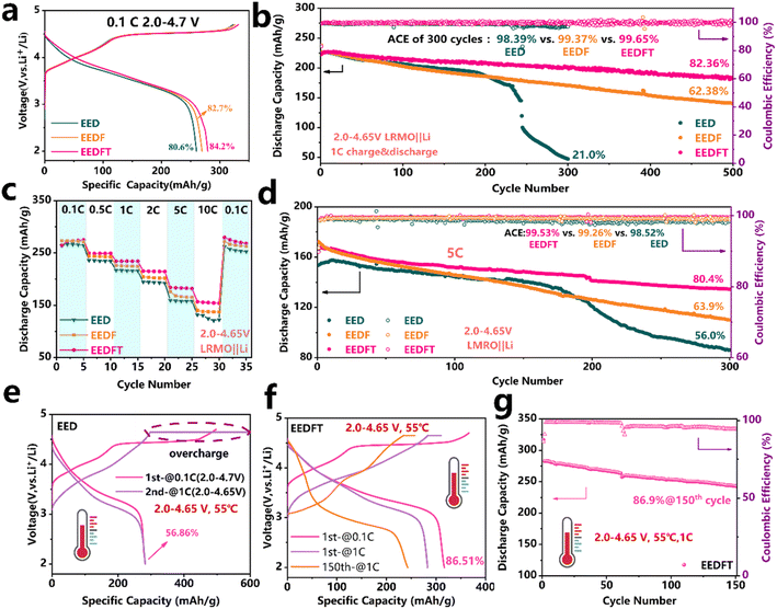
LRMO‖Li half cells were assembled to assess the practicality of the dual additive strategy in the electrolyte. The initial charge–discharge curves of the cells at a current density of 0.1 C (1 C = 250 mA g−1) with the three electrolytes are shown in Fig. 2a. The results show that the cells using these electrolytes all exhibit typical charge–discharge characteristics of LRMO cathodes, where the charging platform above 4.5 V can be attributed to the activation of the Li2MnO3 phase, and the region below 4.5 V is related to the oxidation of TM and the extraction of Li+ in the LiMO2 phase.40,41 Compared to the cells with EED and EEDF, the cell with EEDFT displays the highest discharge capacity (279.6 mA h g−1) and initial coulombic efficiency (84.2%). Furthermore, it also demonstrates remarkably long-term cycling stability, exhibiting a higher capacity of 183.7 mA h g−1 after 500 cycles at 1 C, with the highest capacity retention of 82.36% and the highest average coulombic efficiency of 99.65%. In comparison, those of the cells with EEDF are 140.2 mA h g−1, 65.38% and 99.37%, respectively, while the cells using EED completely fail after 300 cycles (Fig. 2b). In addition, the cells using EEDFT also show inhibited voltage decay and electrochemical polarization (Fig. S3 and S4†). The above results indicate that dual additives can promote the desolvation process of Li+ in EEDFT and construct a stable CEI/SEI during the cycle, so as to ensure high Li+ utilization, a high Li+ migration rate and inhibited interfacial side reactions. Consequently, the cell using EEDFT exhibits superior rate performance compared to that using EED and EEDF, with the discharge capacities of 264.3, 249.6, 234.4, 215.4, 184.2, and 156.7 mA h g−1 at 0.1–10 C (Fig. 2c and S5†). Even at a high current density of 5 C, the cell using EEDFT can operate stably for 300 cycles with a capacity retention of up to 80.4%, which is only 56.0% and 63.9% in the EED and EEDFT (Fig. 2d and S6†), respectively. The electrolyte modified by dual-additives reveals significant advantages compared to previously reported electrolytes for LRMO cathodes (Table S2†).To verify the high-temperature tolerance of the electrolytes, the electrochemical performance of the LRMO cells at 55 °C was further evaluated. As shown in Fig. 2e, the charging capacity of the cell using EED is as high as 500 mA h g−1 at a lower current density of 0.1 C, with the initial coulombic efficiency as low as 56.86%, while the charging capacity is up to 600 mA h g−1 when the current density is increased to 1 C, indicating that EED exhibits serious instability at high temperatures and deteriorates even more at high current density. While for the cell using EEDFT, it can operate normally at 55 °C and maintain a retention rate of up to 86.9% after 150 cycles at 1 C (Fig. 2f and g), suggesting that TMSPa and FEC can improve the intrinsic thermal stability of the electrolyte and multiphase interface stability of the batteries by synergistically regulating the solvation structure. Notably, as shown in Fig. 2f, the 150th charge–discharge curve of the battery using EEDFT indicates that the LRMO cathode is undergoing severe structural phase transition and interface side reactions. However, by combining the early failure of batteries using EED and comparing the charge–discharge curves of the two electrolytes at 30 °C (Fig. 2e and S7†), it can be concluded that the dual addition strategy can effectively delay the occurrence of the irreversible phase transition and reduce interface side reactions.
2.3 Microstructure characterization and interfacial chemical analysis of LRMO cathodes
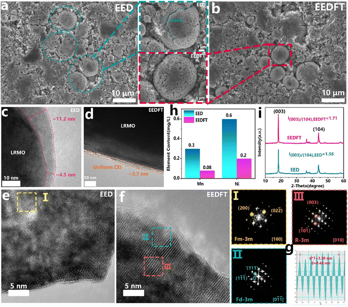
The structural stability of the LRMO cathodes cycled in EED and EEDFT was further compared. First, as shown in Fig. 3a and c, many transgranular cracks can be observed in the LRMO particles after cycling in EED, and an uneven and thick CEI (∼11.2 nm) is generated on the surface of the primary particles, which indicates that EED will decompose severely during cycling, thus inducing side reactions such as interface corrosion, TM ion dissolution, and oxygen release, ultimately resulting in continuous deterioration of cycling and kinetic performance. From a more microscopic scale, as shown in the high-resolution transmission electron microscopy (HRTEM) images in Fig. 3e, the crystal structures at the surface and interior of primary particles cycled in EED have been degraded from a layered structure (R![[3 with combining macron]](https://www.rsc.org/images/entities/char_0033_0304.gif) m) to a rocksalt structure (Fm
m) to a rocksalt structure (Fm![[3 with combining macron]](https://www.rsc.org/images/entities/char_0033_0304.gif) m), and suffered severe dissolution of TM ions (Fig. 3h).
m), and suffered severe dissolution of TM ions (Fig. 3h).
In sharp contrast, the secondary particles of LRMO cathodes cycled in EEDFT maintain the complete spherical morphology, and a uniform and thin CEI (∼4 nm) is formed on the surface of the primary particles during cycling, indicating that the introduced dual additives can enhance the oxidative stability of the electrolyte to reduce the adverse reactions and induce the formation of a stable CEI (Fig. 3b and d). The HRTEM image and the corresponding FFT pattern (Fig. 3f, g and S8†) show that the interior of the particles cycled in EEDFT basically maintains a layered structure, with only the surface structures within 5 nm degenerating into spinel structures (Fd![[3 with combining macron]](https://www.rsc.org/images/entities/char_0033_0304.gif) m), and the dissolution of transition metal ions is significantly suppressed (Fig. 3h). In addition, as confirmed by the X-ray diffraction (XRD) patterns (Fig. 3i), the intensity ratio of the (003)/(104) diffraction peak of the cathode with EEDFT is 1.71, higher than that of EED (1.56), indicating that the LRMO cathodes in EEDFT basically maintain the ordered layered structure, while the cathodes in EED suffer from severe interface reactions and structural degradation due to electrolyte decomposition and acid erosion.
m), and the dissolution of transition metal ions is significantly suppressed (Fig. 3h). In addition, as confirmed by the X-ray diffraction (XRD) patterns (Fig. 3i), the intensity ratio of the (003)/(104) diffraction peak of the cathode with EEDFT is 1.71, higher than that of EED (1.56), indicating that the LRMO cathodes in EEDFT basically maintain the ordered layered structure, while the cathodes in EED suffer from severe interface reactions and structural degradation due to electrolyte decomposition and acid erosion.
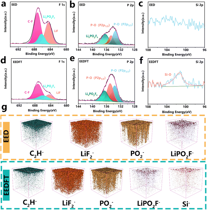
The chemical properties of the CEI were further investigated using X-ray photoelectron spectroscopy (XPS) and time of flight secondary ion mass spectrometry (ToF-SIMS). The F 1s, P 2p, and Si 2p XPS spectra in Fig. 4a–f show that the CEI derived from EEDFT is rich in inorganic species such as LiF, P–O, and Si–O, which can facilitate the migration of Li+. In particular, compared with EED, stronger signals related to P–O species are detected in the CEI derived from EEDFT, on account of the preferential oxidation decomposition of TMSPa on the surface of a high-voltage cathode, which promotes the formation of the phosphatide-rich CEI film. For the EED-derived CEI, a higher content of LixPOyFz generated by the poor decomposition of PF6− is observed (Fig. 4b and e), while the introduction of dual additives can not only suppress the poor decomposition of PF6− by regulating the solvation structure of the electrolyte, but also slow down the interfacial reaction by the scavenging effect of TMSPa on HF, thereby inhibiting the continuous dissolution and reconstruction of the CEI. The components of the CEI were further investigated using ToF-SIMS (Fig. 4g and S9–S11†). The depth profiles of LiPO2F− and C2H− and corresponding 3D rendering images indicate that the CEI derived from EED contains a high content of harmful species generated by the decomposition of solvents and lithium salts. In contrast, the CEI of the cathodes cycled in EEDFT contains more abundant inorganic species related to LiF2−, PO2−, and Si−, which are important components for forming a robust CEI, and can facilitate the rapid de/intercalation of Li+ and inhibit the interfacial side reactions, as confirmed by EIS analysis of LRMO‖Li batteries after cycling (Fig. S12 and Table S3†). In summary, FEC-TMSPa can synergistically regulate the solvation structure of electrolytes to suppress decomposition at high voltage, and promote the formation of a uniform CEI rich-in P, F, and Si species at the LRMO-electrolyte interface, thereby improving the interface charge transport ability and ensuring the long-term stable cycling of LRMO batteries.
2.4 The impact of the FEC-TMSPa additives on homogeneous lithium deposition
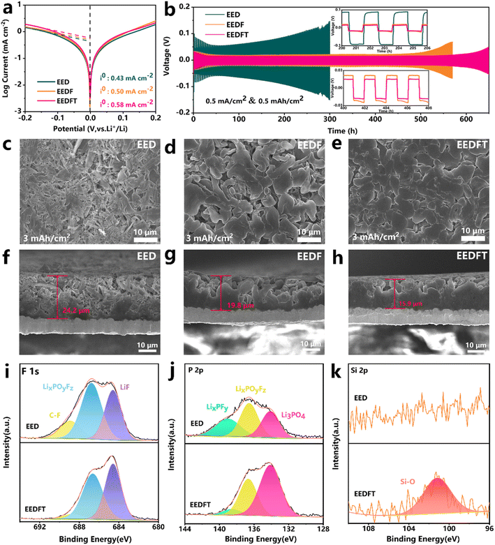
Further exploration was conducted on the mechanism of dual additives on the Li metal anode. As shown in the Tafel curves of Li‖Li symmetric cells with various electrolytes (Fig. 5a), the sequential addition of FEC and TMSPa additives increases the exchange current density (i0) from 0.43 to 0.50 and then to 0.58 mA cm−2, indicating that dual additives can facilitate the reduction of the diffusion barrier of Li+ at the electrode–electrolyte interface, thus ensuring faster electrochemical reaction kinetics. Subsequently, the deposition/stripping behavior of Li+ was further evaluated. Fig. 5b illustrates the long-term electrochemical performance of Li‖Li symmetric cells at a current density of 0.5 mA cm−2. The results show that the cells employing EED and EEDF electrolytes exhibit cycling stability for 300 h and 500 h, respectively, whereas those using EEDFT electrolyte demonstrate a long-term stability for over 600 h with a minimal overpotential. The deposition morphology of Li+ in different electrolytes was observed at the microcosmic scale. Fig. 5c–h show the deposition morphology of lithium in different electrolytes on the Cu collector at 0.5 mA cm−2/3 mA h cm−2. It is clear that the deposited lithium in EED exhibits a highly loose and porous deposition morphology, accompanied by abundant whisker-like lithium dendrites and a thicker deposition layer (∼24.2 μm), due to the poor compatibility of traditional carbonate-based electrolytes with lithium metal. After the addition of FEC, the deposited Li grains become coarser and the surfaces are smoother, but still contain needle shaped grains and the deposition morphology is relatively loose. After further introduction of TMSPa, the lithium deposition layer becomes more dense and smooth, and the thickness (∼15.9 μm) is thinner than that in EED (∼24.2 μm) and EEDF (∼19.8 μm), highlighting the positive role of dual additives in regulating deposition/stripping behavior of Li+.The chemical compositions of the SEI on the Li metal anode were analyzed by XPS. As shown in Fig. S13,† compared with EEDFT, the SEI derived from EED contains more C![[double bond, length as m-dash]](https://www.rsc.org/images/entities/char_e001.gif) O and C–O species generated by solvent decomposition, and generally has lower strength and tends to result in non-uniform Li deposition.42 Meanwhile, more LixPOyFz and LixPFy can be observed in the EED-derived SEI, which are byproducts of the poor decomposition of lithium salt (Fig. 5i–k). In stark contrast, the SEI induced by EEDFT contains higher concentrations of inorganic species such as LiF, Li3PO4, and Si–O, as well as relatively fewer inert carbon-based species, indicating that TMSPa and FEC can be reduced at the anode interface to form a robust SEI rich in inorganic substances, thereby promoting rapid migration of Li+, suppressing interface side reactions, and ensuring the long-term cycling stability of the cells using EEDFT.
O and C–O species generated by solvent decomposition, and generally has lower strength and tends to result in non-uniform Li deposition.42 Meanwhile, more LixPOyFz and LixPFy can be observed in the EED-derived SEI, which are byproducts of the poor decomposition of lithium salt (Fig. 5i–k). In stark contrast, the SEI induced by EEDFT contains higher concentrations of inorganic species such as LiF, Li3PO4, and Si–O, as well as relatively fewer inert carbon-based species, indicating that TMSPa and FEC can be reduced at the anode interface to form a robust SEI rich in inorganic substances, thereby promoting rapid migration of Li+, suppressing interface side reactions, and ensuring the long-term cycling stability of the cells using EEDFT.
3 Conclusion
In summary, we incorporated FEC and TMSPa as multifunctional additives into the commercial LiPF6−-based carbonate electrolyte to optimize the solvation structure of the electrolyte and regulate interface chemistry, thereby achieving long-term cycling stability of the LRMO‖Li cells at high voltage and high temperature. Specifically, the addition of FEC-TMSPa dual additives can effectively weaken the coordination environment of Li+, thus promoting the desolvation process of Li+, and accelerating the reaction kinetics at the electrode surface. Simultaneously, the dual additives can also induce a homogeneous and dense electrode–electrolyte interphase (CEI/SEI) rich in inorganic components, which can effectively protect the electrode from the attack of HF and suppress structure degradation, thereby ensuring the long-term cycle stability of the cells. The electrochemical performance evaluation confirms that the LRMO‖Li battery with dual-additive modified electrolyte maintains a higher capacity retention of 82.36% after 500 cycles at 30 °C, and even achieves a capacity retention of up to 86.9% after 150 cycles at 55 °C. We believe that this simple dual-additive strategy provides a new perspective for the design of high-voltage, high-energy density, and wide-temperature rechargeable batteries.4 Experimental
4.1 Electrolyte and electrode preparation
Li-rich layered oxide Li1.2Ni0.267Mn0.533O2 was prepared by the co-precipitation method. Specifically, an aqueous solution of 2 M MnSiO4·H2O and NiSiO4·6H2O with the desired molar ratio were added into a 5 L stirring tank reactor. Meantime, a solution of 2 M Na2CO3 and a solution of 0.24 M NH4·H2O were slowly pumped into the reactor, acting as the precipitation agent and chelation agent. During the co-precipitation, the parameters such as stirring rate (1000 rpm) and pH (7.8) were regulated carefully. The collected precursor was washed with anhydrous ethanol and dried in a vacuum oven for 12 h. Then, the obtained sample was mixed with Li2CO3 (Li/TM = 1.50), and the mixture was pretreated at 500 °C for 6 h and calcined at 900 °C for 15 h in an air atmosphere to obtain the LRMO material.The LRMO cathode was prepared by mixing LRMO, carbon black, and poly(vinylidene fluoride) (PVDF) (8![[thin space (1/6-em)]](https://www.rsc.org/images/entities/char_2009.gif) :
:![[thin space (1/6-em)]](https://www.rsc.org/images/entities/char_2009.gif) 1
1![[thin space (1/6-em)]](https://www.rsc.org/images/entities/char_2009.gif) :
:![[thin space (1/6-em)]](https://www.rsc.org/images/entities/char_2009.gif) 1, by weight) and coating the mixture on Al foil that was then dried at 80 °C and cut into discs, followed by drying under vacuum for nearly 12 h.
1, by weight) and coating the mixture on Al foil that was then dried at 80 °C and cut into discs, followed by drying under vacuum for nearly 12 h.
Lithium hexafluorophosphate (LiPF6), ethylene carbonate (EC), ethyl methyl carbonate (EMC), dimethyl carbonate (DMC), and fluoroethylene carbonate (FEC) were purchased from DoDochem. And tris(trimethylsilyl)phosphate (TMSPa) was purchased from Aladdin. Four different electrolytes were prepared: 1.0 M LiPF6 in EC/EMC/DMC (1![[thin space (1/6-em)]](https://www.rsc.org/images/entities/char_2009.gif) :
:![[thin space (1/6-em)]](https://www.rsc.org/images/entities/char_2009.gif) 2
2![[thin space (1/6-em)]](https://www.rsc.org/images/entities/char_2009.gif) :
:![[thin space (1/6-em)]](https://www.rsc.org/images/entities/char_2009.gif) 2 in weight) was denoted as “EED”; EED with 5 wt% FEC was denoted as “EEDF”; EED with 1 wt% TMSPa was denoted as “EEDT”; and EEDF with 1 wt% TMSPa was denoted as “EEDFT”. All electrolytes were prepared in an argon-filled glove box with oxygen and moisture contents below 0.5 ppm (parts per million).
2 in weight) was denoted as “EED”; EED with 5 wt% FEC was denoted as “EEDF”; EED with 1 wt% TMSPa was denoted as “EEDT”; and EEDF with 1 wt% TMSPa was denoted as “EEDFT”. All electrolytes were prepared in an argon-filled glove box with oxygen and moisture contents below 0.5 ppm (parts per million).
4.2 Electrochemical measurements
2016-type Li‖LRMO coin cells were assembled with a Celgard 2500 membrane and 60 μL of the electrolytes in a glove box. Galvanostatic charge/discharge measurements were conducted on a multichannel battery tester (NEWARE). Li‖LRMO cells were activated at 0.1 C (1 C = 250 mA g−1) in the first cycle (cut off voltage: 2–4.7 V), and then cycled with 1 C constant current during the long-term cycling (cut off voltage: 2–4.65 V). Linear sweep voltammetry (LSV) was conducted on a Parstant 4000 A electrochemical workstation. Stainless steel (SS) electrodes were chosen as the reference electrodes to form Li‖SS cells in the LSV measurement.4.3 Materials characterization
A Bruker Advance D8 powder X-ray diffractometer (XRD) and field emission scanning electron microscope (Nova Nano SEM230, USA) were used to obtain the morphology of the LRMO samples. A nuclear Magnetic Resonance (NMR) spectrometer (AVANCE III 400 M) was used to probe the 7Li chemical environment for different electrolytes. Cycled cells were disassembled in a glove box and the cathodes were dried at 45 °C after washing repeatedly with EMC solvent. The collected solvent was analyzed by inductively coupled plasma-atomic emission spectroscopy (ICP-AES) to evaluate the transition metals (TMs) dissolved in electrolyte. The surface chemical compositions of cycled cathodes were evaluated by X-ray photoelectron spectroscopy (XPS). Surface morphology was characterized on a transmission electron microscope (TEM, Talos F200X). Time of flight secondary ion mass spectrometry (TOF-SIMS, PHI nano TOF3) was used to analyze CEl chemical information with depth profiles.4.4 Computational details
In this system, the x, y, and z dimensions were periodic boundary conditions. The OPLS force field, which is suitable for electrolyte solution, was used to optimize sample structures for preliminary structural optimization. Atomic charges of ions were multiplied by a scale factor of 0.73 to correct the polarization effect of anions and cations. First, the conjugate gradient algorithm and energy minimization were performed to obtain a stable structure before using dynamic simulations. Each sample was then equilibrated under the NPT ensemble at a constant temperature of 400 K to achieve an equilibrium state with zero pressure for 5 ns. Subsequently, the system temperature was reduced from 400 K to 298 K for annealing for 5 ns under the NPT ensemble (under 1 atmosphere). The Andersen feedback thermostat and Berendsen barostat algorithm were applied in the system with temperature and pressure conversion. Next, MD simulations were further carried out for 10 ns with a time step of 1 fs per integration step under the ensemble conditions of NVT (298 K). System energy can be obtained through structural optimization using energy minimization.Data availability
The data supporting this article have been included as part of the ESI.† And data are available upon request from the authors.Author contributions
Qiangfeng Zhang: conceptualization, investigation, data curation, validation, writing – original draft. Shijie Xu: investigation, methodology, data curation. Haipeng Zhu: investigation, data curation, writing – original draft. Zhao Chen: investigation, data curation. Libao Chen: writing – review & editing, resources, supervision. Chunxiao Zhang: conceptualization, writing – review & editing, resources, supervision, project administration, funding acquisition. Weifeng Wei: writing – review & editing, resources, supervision.Conflicts of interest
There are no conflicts to declare.Acknowledgements
The authors would like to acknowledge financial support from the National Natural Science Foundation of China (51971250 and 52407257), the Natural Science Foundation of Hunan Province, China (No. 2023JJ40759), and the State Key Laboratory of Powder Metallurgy at Central South University.References
- Z. Yu, H. Wang, X. Kong, W. Huang, Y. Tsao, D. G. Mackanic, K. Wang, X. Wang, W. Huang, S. Choudhury, Y. Zheng, C. V. Amanchukwu, S. T. Hung, Y. Ma, E. G. Lomeli, J. Qin, Y. Cui and Z. Bao, Nat. Energy, 2020, 5, 526–533 CrossRef CAS.
- J. Zhao, X. Zhang, Y. Liang, Z. Han, S. Liu, W. Chu and H. Yu, ACS Energy Lett., 2021, 6, 2552–2564 CrossRef CAS.
- C. Zhang, W. Jiang, W. He and W. Wei, Energy Storage Mater., 2021, 37, 161–189 CrossRef.
- X. Wang, R. Kerr, F. Chen, N. Goujon, J. M. Pringle, D. Mecerreyes, M. Forsyth and P. C. Howlett, Adv. Mater., 2020, 32, 1905219 CrossRef CAS PubMed.
- W.-J. Kong, C.-Z. Zhao, S. Sun, L. Shen, X.-Y. Huang, P. Xu, Y. Lu, W.-Z. Huang, J.-Q. Huang and Q. Zhang, Adv. Mater., 2024, 36, 2310738 CrossRef CAS PubMed.
- Z. Lu, D. Liu, K. Dai, K. Liu, C. Jing, W. He, W. Wang, C. Zhang and W. Wei, Energy Storage Mater., 2023, 57, 316–325 CrossRef.
- C. Zhang, Z. Lu, M. Song, Y. Zhang, C. Jing, L. Chen, X. Ji and W. Wei, Adv. Energy Mater., 2023, 13, 2203870 CrossRef CAS.
- W. Jiang, C. Zhang, Y. Feng, B. Wei, L. Chen, R. Zhang, D. G. Ivey, P. Wang and W. Wei, Energy Storage Mater., 2020, 32, 37–45 CrossRef.
- W. He, C. Zhang, M. Wang, B. Wei, Y. Zhu, J. Wu, C. Liang, L. Chen, P. Wang and W. Wei, Adv. Funct. Mater., 2022, 32, 2200322 CrossRef CAS.
- D. Liu, J. Yang, Z. Fang, T. Feng, Z. Xu, X. Liu and M. Wu, Chem. Eng. J., 2023, 470, 144404 CrossRef CAS.
- D. Eum, B. Kim, S. J. Kim, H. Park, J. Wu, S.-P. Cho, G. Yoon, M. H. Lee, S.-K. Jung, W. Yang, W. M. Seong, K. Ku, O. Tamwattana, S. K. Park, I. Hwang and K. Kang, Nat. Mater., 2020, 19, 419–427 CrossRef CAS PubMed.
- W. Li, B. Song and A. Manthiram, Chem. Soc. Rev., 2017, 46, 3006–3059 RSC.
- J.-L. Shi, J.-N. Zhang, M. He, X.-D. Zhang, Y.-X. Yin, H. Li, Y.-G. Guo, L. Gu and L.-J. Wan, ACS Appl. Mater. Interfaces, 2016, 8, 20138–20146 CrossRef CAS.
- B. Acebedo, M. C. Morant-Miñana, E. Gonzalo, I. Ruiz de Larramendi, A. Villaverde, J. Rikarte and L. Fallarino, Adv. Energy Mater., 2023, 13, 2203744 CrossRef CAS.
- S. Gao, F. Sun, N. Liu, H. Yang and P.-F. Cao, Mater. Today, 2020, 40, 140–159 CrossRef CAS.
- W. Xu, J. Wang, F. Ding, X. Chen, E. Nasybulin, Y. Zhang and J.-G. Zhang, Energy Environ. Sci., 2014, 7, 513–537 RSC.
- Y. Zhang, T.-T. Zuo, J. Popovic, K. Lim, Y.-X. Yin, J. Maier and Y.-G. Guo, Mater. Today, 2020, 33, 56–74 CrossRef CAS.
- S. Park, H.-J. Jin and Y. S. Yun, Adv. Mater., 2020, 32, 2002193 CrossRef CAS.
- T. Zhou, H. Wang, Y. Wang, P. Jiao, Z. Hao, K. Zhang, J. Xu, J.-B. Liu, Y.-S. He, Y.-X. Zhang, L. Chen, L. Li, W. Zhang, Z.-F. Ma and J. Chen, Chem, 2022, 8, 2817–2830 CAS.
- X. Gao, L. Wang, J. Guo, S. Li, H. Zhang, L. Chen, Y. Zhang, Y. Lai and Z. Zhang, Adv. Funct. Mater., 2024, 2407692 CrossRef CAS.
- Q. Li, D. Zhou, L. Zhang, D. Ning, Z. Chen, Z. Xu, R. Gao, X. Liu, D. Xie, G. Schumacher and X. Liu, Adv. Funct. Mater., 2019, 29, 1806706 CrossRef.
- E. Wang, D. Xiao, T. Wu, X. Liu, Y. Zhou, B. Wang, T. Lin, X. Zhang and H. Yu, Adv. Funct. Mater., 2022, 32, 2201744 CrossRef CAS.
- J. Li, C. Zhan, J. Lu, Y. Yuan, R. Shahbazian-Yassar, X. Qiu and K. Amine, ACS Appl. Mater. Interfaces, 2015, 7, 16040–16045 CrossRef CAS PubMed.
- W. M. Dose, W. Li, I. Temprano, C. A. O'Keefe, B. L. Mehdi, M. F. L. De Volder and C. P. Grey, ACS Energy Lett., 2022, 7, 3524–3530 CrossRef CAS PubMed.
- F. Li, J. Liu, J. He, Y. Hou, H. Wang, D. Wu, J. Huang and J. Ma, Angew. Chem., Int. Ed., 2022, 61, e202205091 CrossRef CAS PubMed.
- J. Liu, B. Yuan, N. He, L. Dong, D. Chen, S. Zhong, Y. Ji, J. Han, C. Yang, Y. Liu and W. He, Energy Environ. Sci., 2023, 16, 1024–1034 RSC.
- X. Li, J. Liu, J. He, H. Wang, S. Qi, D. Wu, J. Huang, F. Li, W. Hu and J. Ma, Adv. Funct. Mater., 2021, 31, 2104395 CrossRef CAS.
- F. Li, J. He, J. Liu, M. Wu, Y. Hou, H. Wang, S. Qi, Q. Liu, J. Hu and J. Ma, Angew. Chem., Int. Ed., 2021, 60, 6600–6608 CrossRef CAS PubMed.
- K. Liu, Q. Zhang, Z. Lu, H. Zhu, M. Song, L. Chen, C. Zhang and W. Wei, ACS Appl. Mater. Interfaces, 2024, 16, 14902–14911 CrossRef CAS PubMed.
- T. Lin, T. U. Schulli, Y. Hu, X. Zhu, Q. Gu, B. Luo, B. Cowie and L. Wang, Adv. Funct. Mater., 2020, 30, 1909192 CrossRef CAS.
- S. Li, C. Guan, W. Zhang, H. Li, X. Gao, S. Zhang, S. Li, Y. Lai and Z. Zhang, Small, 2023, 19, 2303539 CrossRef CAS PubMed.
- X. Li, M. Li, Y. Liu, Y. Jie, W. Li, Y. Chen, F. Huang, Y. Zhang, T. M. Sohail, S. Wang, X. Zhu, T. Cheng, M. D. Gu, S. Jiao and R. Cao, J. Am. Chem. Soc., 2024, 146, 17023–17031 CrossRef CAS PubMed.
- V. Reisecker, F. Flatscher, L. Porz, C. Fincher, J. Todt, I. Hanghofer, V. Hennige, M. Linares-Moreau, P. Falcaro, S. Ganschow, S. Wenner, Y. M. Chiang, J. Keckes, J. Fleig and D. Rettenwander, Nat. Commun., 2023, 14, 2432 CrossRef CAS PubMed.
- M. Tao, X. Chen, H. Lin, Y. Jin, P. Shan, D. Zhao, M. Gao, Z. Liang and Y. Yang, ACS Nano, 2023, 17, 24104–24114 CrossRef CAS PubMed.
- J.-Y. Liang, X.-D. Zhang, Y. Zhang, L.-B. Huang, M. Yan, Z.-Z. Shen, R. Wen, J. Tang, F. Wang, J.-L. Shi, L.-J. Wan and Y.-G. Guo, J. Am. Chem. Soc., 2021, 143, 16768–16776 CrossRef CAS PubMed.
- Y. Liu, Y. Lin, Z. Yang, C. Lin, X. Zhang, S. Chen, G. Hu, B. Sa, Y. Chen and Y. Zhang, ACS Nano, 2023, 17, 19625–19639 CrossRef CAS PubMed.
- X. Fan and C. Wang, Chem. Soc. Rev., 2021, 50, 10486–10566 RSC.
- C. Bolli, A. Guéguen, M. A. Mendez and E. J. Berg, Chem. Mater., 2019, 31, 1258–1267 CrossRef CAS.
- Y. Wang, Z. Wu, F. M. Azad, Y. Zhu, L. Wang, C. J. Hawker, A. K. Whittaker, M. Forsyth and C. Zhang, Nat. Rev. Mater., 2024, 9, 119–133 CrossRef CAS.
- D. Liu, X. Fan, Z. Li, T. Liu, M. Sun, C. Qian, M. Ling, Y. Liu and C. Liang, Nano Energy, 2019, 58, 786–796 CrossRef CAS.
- L. Wang, A. Dai, W. Xu, S. Lee, W. Cha, R. Harder, T. Liu, Y. Ren, G. Yin, P. Zuo, J. Wang, J. Lu and J. Wang, J. Am. Chem. Soc., 2020, 142, 14966–14973 CrossRef CAS.
- X. Zhang, P. Xu, J. Duan, X. Lin, J. Sun, W. Shi, H. Xu, W. Dou, Q. Zheng, R. Yuan, J. Wang, Y. Zhang, S. Yu, Z. Chen, M. Zheng, J.-F. Gohy, Q. Dong and A. Vlad, Nat. Commun., 2024, 15, 536 CrossRef CAS PubMed.
Footnote |
| † Electronic supplementary information (ESI) available. See DOI: https://doi.org/10.1039/d4ta05141f |
| This journal is © The Royal Society of Chemistry 2025 |

