Modulating the electronic interactions via heterostructure engineering for energy-saving hydrogen production at high current densities†
Dongxing
Tan
*,
Xianfang
Yin
,
Jing
Wang
,
Zixuan
Zhang
,
Xiao
Zhu
 ,
Hengrui
Kang
and
Yuanyuan
Feng
*
Key Laboratory of Catalytic Conversion and Clean Energy in Universities of Shandong Province, School of Chemistry and Chemical Engineering, Qufu Normal University, Qufu, Shandong 273165, P. R. China. E-mail: tandx@qfnu.edu.cn; fengyy@qfnu.edu.cn
First published on 29th October 2024
Abstract
Advanced alkaline hydrogen evolution reaction (HER) catalysts should exhibit a low water dissociation energy barrier and fast reaction kinetics. However, single-component transition metal catalysts typically show insufficient activation of water, leading to unsatisfactory electrocatalytic activity. Rationally modulating the composition and constructing heterogeneous interfaces can effectively regulate the interfacial electronic structure of catalysts, thereby improving the kinetics and catalytic activity of the alkaline HER. Herein, Ni0.2Mo0.8N/F,N–C@NF heterogeneous catalyst was prepared, demonstrating excellent alkaline HER activity (281 mV @ 1000 mA cm−2). Experimental results and density functional theory (DFT) calculations indicate that heterogeneous engineering can effectively modulate the surface charge structure of catalysts, enhancing the adsorption and activation of reactive intermediates. Simultaneously, heterogeneous engineering accelerates reaction kinetics by further reducing the energy barrier of the Tafel step. The Ni0.2Mo0.8N/F,N–C@NF catalyst also exhibits satisfactory catalytic activity towards the HER when integrated with a methanol oxidation reaction. This work provides an effective guide for the rational design of high-performance alkaline HER electrocatalysts for energy-saving hydrogen production.
Introduction
Hydrogen (H2), as a renewable and sustainable resource, is an ideal alternative energy to traditional fossil fuels.1–3 It is both promising and crucial to produce H2 through environmentally friendly and cost-effective means. The production of green H2via overall water splitting (OWS) has gained significant attention. OWS consists of a hydrogen evolution reaction (HER) at the cathode and an oxygen evolution reaction (OER) with a high thermodynamic equilibrium potential (1.23 V versus reversible hydrogen electrode, RHE) at the anode.4–6 However, the kinetically sluggish OER consumes about 90% of the input electricity, severely limiting the efficiency of H2 production and increasing the overall cost.7,8 To maximize energy utilization, it is urgent and more meaningful to combine HER with thermodynamically favorable oxidation reactions.9 Electrocatalytic oxidation of organic molecules has been proposed as a replacement for the traditional OER. These organic molecular oxidation reactions can significantly reduce energy consumption, and the value-added oxidative products are key intermediates in the pharmaceutical and chemical industries.10–15Methanol, a cheap and widely available platform chemical, has been extensively investigated for use in the electrocatalytic methanol oxidation reaction (MOR) integrated with the HER. MOR has a low thermodynamic equilibrium potential (CH3OH + 5OH− → HCOO− + 4H2O + 4e−, 0.103 V vs. RHE) and can produce high value-added formate.16–18 Various catalysts have been designed to enhance the combined HER and methanol-to-formate process. For example, bifunctional 2D exfoliated boron nanosheets have been used for HER integrated with MOR to enable energy-efficient H2 production.12 The hybrid electrolyzer (HER + MOR) requires a significantly lower voltage (@10 mA cm−2) compared to a conventional electrolyzer (HER + OER). Furthermore, the optimized local coordination environment of NiOOH with oxy-anions can regulate the adsorption of OH* and methanol, improving the MOR activity.16 Hence, utilizing the MOR to replace the traditional OER not only offers a promising approach for energy-saving H2 production but also generates high-valued oxidative products at the anode.
Here, we synthesized a heterogeneous catalyst of bimetal nitride (Ni0.2Mo0.8N) embedded in F,N-doped carbon nanoarrays supported on the nickel foam (NF) substrate (denoted as Ni0.2Mo0.8N/F,N–C@NF) to achieve efficient MOR-assisted energy-saving H2 production. Experimental results and DFT calculations show that the interactions between bimetal nitride and F,N-doped carbon greatly facilitate the adsorption and activation of water molecules and accelerate the charge transfer process. Excitingly, the optimized Ni0.2Mo0.8N/F,N–C@NF shows superior activity for HER and MOR in an alkaline solution. Even at the industrial-level current density of 1000 mA cm−2, the Ni0.2Mo0.8N/F,N–C@NF catalyst presents low potentials of 281 and 1483 mV for HER and MOR, respectively. Impressively, simultaneous H2 and formate generation can be achieved when the Ni0.2Mo0.8N/F,N–C@NF acts as both the cathode and the anode for the HER and the MOR.
Results and discussion
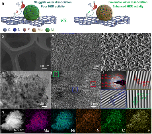
Compared to acidic HER, HER in alkaline electrolytes is more cost-effective and stable, especially at an industrial-grade high current density. However, the alkaline HER exhibits a sluggish kinetic process due to the additional Volmer step (H2O + e− → Had + OH−) for water dissociation.19 Hence, an efficient alkaline HER catalyst should enhance water dissociation kinetics. The composite catalysts with different functional components could accelerate water dissociation kinetics to enhance alkaline HER activity.20 Constructing a heterogeneous interface between bimetallic nitride and F,N-doped carbon, regulating the interface electronic structure, and improving the alkaline HER activity through the interface synergy effect between bimetallic nitride and doped carbon are feasible strategies for designing highly efficient alkaline HER catalysts (Fig. 1a). Furthermore, compared with nickel nitride, the synergistic effect of Ni and Mo in bimetallic nitride could reduce the reaction energy barrier of the Volmer step to improve the alkaline HER activity.21 Consequently, bimetallic nitride/F,N-doped carbon heterogeneous catalyst delivers superior intrinsic electrocatalytic activity.The metal nitride embedded in F,N-doped carbon nanoarrays supported on the three-dimensional porous nickel foam (NF) substrate was constructed through the solvent-thermal combined with a post-treatment strategy (Fig. 1b). The magnified scanning electron microscopy (SEM) images show that the nanoarrays have a 3D honeycomb-like structure (Fig. 1c, d and S1†). This special network structure could expose more active sites and facilitate the desorption of generated gases, thereby accelerating the electrocatalytic process.22 From the transmission electron microscopy (TEM) image, metal nitride particles are embedded in the F,N-doped carbon layer (Fig. 1e). The diffraction rings of the selected area electron diffraction (SAED) pattern and the lattice fringes of high-resolution transmission electron microscopy (HRTEM) images of optimized bimetallic nitride/F,N–C@NF catalyst indicate that there are Ni0.2Mo0.8N and Ni phases from NF in the catalyst (Fig. 1f and g).23,24 Energy-dispersive X-ray spectroscopy (EDS) mapping images indicate that Mo, Ni, N, C and F elements are uniformly distributed in the catalyst (Fig. 1h).
The chemical compositions and electronic structure of the pre-prepared catalysts were investigated by X-ray diffraction (XRD) pattern and X-ray photoelectron spectroscopy (XPS). The characteristic peaks located at 32.2°, 36.5° and 49.4° are indexed to the (001), (100), and (101) planes of Ni0.2Mo0.8N, respectively; the peaks centered at 38.9°, 42.1°, 58.5° and 70.6° are assigned to the (110), (002), (112) and (300) planes of Ni3N, respectively (Fig. S2a†).25,26 The remaining diffraction peaks at 44.5° and 51.8° can be assigned to the (111) and (200) planes of NF substrate.27 In the high-resolution Mo 3d spectra (Fig. S2b†), the binding energies at 229.4 and 232.8 eV, 230.8 and 234.0 eV, as well as 232.3 and 235.5 eV correspond to Mo3+, Mo4+ and Mo6+, respectively.28,29 Specifically, the Mo oxo species with an unusual oxidation state (most likely Mo3+) on the Ni–Mo catalyst was responsible for the high HER activity.30–32 In the high-resolution Ni 2p spectra (Fig. S2c†), the binding energies at 852.7 and 870.1 eV, 855.9 and 873.5 eV, as well as 858.5 and 876.9 eV correspond to Ni–N, Ni2+ and Ni3+, respectively.33,34 It is noteworthy that the binding energies of the Ni 2p in Ni0.2Mo0.8N/F,N–C@NF shifted to the lower binding energies compared with that of Ni3N/N–C@NF (Fig. S3†). This confirms the existence of electronic interactions between the bimetallic nitride and F,N-doped carbon. More importantly, electron-rich active sites could optimize the adsorption energies of H2O and H* to improve HER activities.35 In the high-resolution N 1s spectra (Fig. S2d†), the binding energies at 395.3, 397.5 and 399.2 eV correspond to Mo 3p, metal–N and N–H, respectively.28 The five carbon species in the high-resolution C 1s spectra (Fig. S2e†) correspond to C–C/C![[double bond, length as m-dash]](https://www.rsc.org/images/entities/char_e001.gif) C (B.E. 284.8 eV), C–N (B.E. 286.3 eV), C–O (B.E. 287.3 eV), C–F (B.E. 288.3 eV) and Ph–π* species (B.E. 289.2 eV), respectively.36,37 Meanwhile, the C–F bond was further confirmed by the high-resolution F 1s spectra (Fig. S2f†) with the binding energy at 688.9 eV.38
C (B.E. 284.8 eV), C–N (B.E. 286.3 eV), C–O (B.E. 287.3 eV), C–F (B.E. 288.3 eV) and Ph–π* species (B.E. 289.2 eV), respectively.36,37 Meanwhile, the C–F bond was further confirmed by the high-resolution F 1s spectra (Fig. S2f†) with the binding energy at 688.9 eV.38
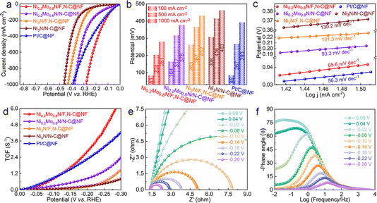
The electrocatalytic performances of the prepared catalysts and commercial Pt/C for the HER were evaluated in three-electrode cells with a 1.0 M KOH solution. As observed from the LSV curves in Fig. 2a, the Ni0.2Mo0.8N/F,N–C@NF exhibits significantly improved HER activity compared to the Ni0.2Mo0.8N/N–C@NF, Ni3N/F,N–C@NF, Ni3N/N–C@NF and commercial Pt/C. To be more specific, the potential required for the Ni0.2Mo0.8N/F,N–C@NF catalyst to drive a current density of 100 mA cm−2 is only 83 mV, which is comparable to the commercial Pt/C@NF. To drive the higher current densities (500 and 1000 mA cm−2), the potentials required for Ni0.2Mo0.8N/F,N–C@NF catalyst are significantly lower than those of the reference catalysts (Fig. 2b). Moreover, the Ni0.2Mo0.8N/F,N–C@NF catalyst has a smaller Tafel slope (65.6 mV dec−1) than that of the Ni3N/N–C@NF catalyst (130.2 mV dec−1), indicating a fast HER kinetic process (Fig. 2c).39 These results indicate that the introduction of F and Mo can accelerate the reaction kinetics and improve the electrocatalytic activity. In addition, the large double layer capacitance (Cdl) of the Ni0.2Mo0.8N/F,N–C@NF catalyst indicates that Ni0.2Mo0.8N/F,N–C@NF has a larger electrochemical surface area (ECSA), which can expose more active sites (Fig. S4†). In addition, the ECSA-normalized HER polarization curves of catalysts indicate that the high catalytic performance of Ni0.2Mo0.8N/F,N–C@NF mainly depends on the improvement of the intrinsic activity of the metal sites rather than the size of the active area (Fig. S5†). The charge transfer during the HER process was evaluated by electrochemical impedance spectroscopy (EIS) (Fig. S6†). The Ni0.2Mo0.8N/F,N–C@NF catalyst has the smallest charge transfer resistance, indicating rapid charge transfer during the electrocatalytic process. Due to the favour kinetics process, large ECSA and fast charge transfer, the Ni0.2Mo0.8N/F,N–C@NF has a large turnover frequency (TOF) (Fig. 2d). The TOFs of Ni0.2Mo0.8N/F,N–C@NF at −0.10 and −0.20 V are 0.82 and 2.83 s−1, respectively, which are 10.6 and 10.3 times those of the Ni3N/N–C@NF. This further proves that rationally modulating the composition and constructing heterogeneous interfaces is a feasible means of improving the activity of alkaline HER.
The in situ potential-dependent Nyquist and Bode plots were used to further explore the charge transfer kinetics of the catalytic processes. The radius of the semicircular arc gradually decreases with a decrease in the applied potential, indicating a decrease in charge transfer impedance (Fig. 2e and S7a†). In the Bode plots, the phase angle (θ) in the low-frequency region corresponds to underpotentially deposited hydrogen, while the θ in the high-frequency region corresponds to charge transfer from the inner layer of the catalyst to the surface active site.40–42 There is a significant difference in the decreasing trend in the different frequency regions as the applied potential changes for Ni0.2Mo0.8N/F,N–C@NF and Ni3N/N–C@NF (Fig. 2f and S7b†). Ni0.2Mo0.8N/F,N–C@NF displays a low θ in the high frequency than that of Ni3N/N–C@NF, indicating a favourable kinetic process. Meanwhile, as the potential decreases, the θ in the low-frequency region gradually decreases, implying that the Ni0.2Mo0.8N/F,N–C@NF can accelerate the dissociation of water and promote the transfer of electrons to active sites. Due to the favourable kinetics and rapid charge transfer, the HER catalytic performance of Ni0.2Mo0.8N/F,N–C@NF is superior or comparable to that of the currently reported state-of-the-art electrocatalysts in the literature (Table S1†).
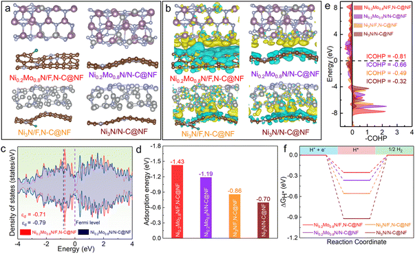
According to the experimental results of the structural analysis, Ni0.2Mo0.8N/F,N–C@NF, Ni0.2Mo0.8N/N–C@NF, Ni3N/F,N–C@NF and Ni3N/N–C@NF models were constructed to reveal the synergistic impacts of heterogeneous engineering through DFT calculations (Fig. 3a). As shown in Fig. 3b, there are obvious charge transfers at the heterogeneous interface between the Ni0.2Mo0.8N or Ni3N and doped carbon nanoarrays. The charge accumulation on Ni0.2Mo0.8N and Ni3N indicates that Ni0.2Mo0.8N and Ni3N have acceptor properties, while F,N-doped carbon and N-doped carbon have donor properties. It is noteworthy that the charge distributions for the atoms in the top layer of Ni0.2Mo0.8N/F,N–C@NF and Ni3N/F,N–C@NF change more significantly compared to Ni0.2Mo0.8N/N–C@NF and Ni3N/N–C@NF. This demonstrates that the introduction of F atoms further enhances the interactions between the bimetal nitride and carbon nanoarrays. Subsequently, the projected density of state (PDOS) analysis shows that the Mo-3d orbitals in Ni0.2Mo0.8N/F,N–C@NF and Ni0.2Mo0.8N/N–C@NF exhibit higher electron density near the Fermi level than Ni-3d orbitals in Ni3N/F,N–C@NF and Ni3N/N–C@NF. The corresponding d-band center (εd) values of Mo atoms of Ni0.2Mo0.8N/F,N–C@NF, Ni0.2Mo0.8N/N–C@NF, and Ni atoms of Ni3N/F,N–C@NF and Ni3N/N–C@NF are −0.71, −0.79, −1.28 and −1.72 eV, respectively (Fig. 3c and S8†). In particular, the εd value of Ni0.2Mo0.8N/F,N–C@NF is located closer to the Fermi level, which may make it more activated and favored for the adsorption of reactive intermediates.35
To further understand the mechanism of HER electrocatalytic processes and gain insights into the excellent HER activity of the Ni0.2Mo0.8N/F,N–C@NF heterogeneous catalyst, the adsorption of water molecules on catalysts was further evaluated (Fig. S9†). Because the Volmer step (H2O + e− → Had + OH−) for water dissociation limits the activity of alkaline HER, the effective adsorption and activation of water molecules on the catalyst surface are crucial for improving alkaline HER activity.19Fig. 3d shows that the adsorption energy of the Ni0.2Mo0.8N/F,N–C@NF for water molecules is −1.43 eV, which is more negative compared to that of Ni0.2Mo0.8N/N–C@NF (−1.19 eV), Ni3N/F,N–C@NF (−0.86 eV) and Ni3N/N–C@NF (−0.70 eV). Then, the bonding-antibonding strengths between Mo sites of Ni0.2Mo0.8N/F,N–C@NF, Ni0.2Mo0.8N/N–C@NF, and Ni sites of Ni3N/F,N–C@NF and Ni3N/N–C@NF sites and the O atom of the *OH2 were quantitatively examined using the COHP method.40,41 As shown in Fig. 3e, the value of ICOHP (−0.81 eV) of Ni0.2Mo0.8N/F,N–C@NF interacting with *OH2 is smaller than that of Ni0.2Mo0.8N/N–C@NF (−0.66 eV), Ni3N/F,N–C@NF (−0.49 eV) and Ni3N/N–C@NF (−0.32 eV), which implies that Ni0.2Mo0.8N/F,N–C@NF has a stronger bonding strength with *OH2.43 This further indicates that the synergy of heterogeneous engineering can promote the adsorption and activation of water molecules, thereby enhancing the alkaline HER activity. The ΔGH* is an important parameter for evaluating HER activity. The ΔGH* of Ni0.2Mo0.8N/F,N–C@NF is much closer to 0 eV compared to the Ni0.2Mo0.8N/N–C@NF, Ni3N/F,N–C@NF and Ni3N/N–C@NF (Fig. 3f). This result is consistent with the experimental results, suggesting that heterogeneous engineering can lower the thermodynamic barrier of the reaction process and boost catalytic activity.44
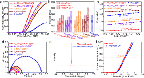
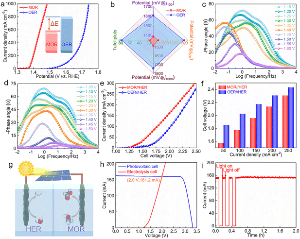
The electrocatalytic activities of OER for catalysts were also evaluated. Although the OER activity of the Ni0.2Mo0.8N/F,N–C@NF catalyst has been improved compared to the reference catalysts, it is still slightly inferior to commercial RuO2 at low current densities (Fig. S10†). This may be attributed to the weak adsorption of oxygen containing intermediates on the catalyst surface. The sluggish OER activity leads to high energy consumption for electrocatalytic H2 production.45 Therefore, the MOR was used to replace the traditional OER. The electrocatalytic MOR performances of the catalysts were investigated in 1.0 M KOH with a 0.5 M methanol solution. As illustrated in Fig. 4a, the Ni0.2Mo0.8N/F,N–C@NF displays an impressive MOR catalytic performance among all the catalysts. To drive the current densities of 100, 500 and 1000 mA cm−2, the required potentials for Ni0.2Mo0.8N/F,N–C@NF are 1387, 1430 and 1483 mV, respectively, which are significantly lower than those of Ni3N/N–C@NF and commercial RuO2@NF (Fig. 4b). The excellent reaction kinetics of Ni0.2Mo0.8N/F,N–C@NF for MOR was also verified by a lower Tafel slope of 17.7 mV dec−1 than those of Ni3N/N–C@NF (22.6 mV dec−1) and commercial RuO2@NF (66.3 mV dec−1) (Fig. 4c). In addition to a low Tafel slope, the Ni0.2Mo0.8N/F,N–C@NF also presents a smaller charge transfer impedance confirmed by EIS (Fig. 4d). The formate produced from the MOR was identified by 1H nuclear magnetic resonance (NMR) (Fig. 4e). After 1000 CV cycles, there is no obvious change in the LSV curve, indicating the good stability of catalytic performance (Fig. 4f).
Compared with OER, the MOR activity of the Ni0.2Mo0.8N/F,N–C@NF was significantly improved (Fig. 5a). This is mainly attributed to the low thermodynamic equilibrium potential and favourable reaction kinetics of MOR. In particular, the Tafel slope of MOR and the potentials required to drive different current densities (100, 500 and 1000 mA cm−2) for Ni0.2Mo0.8N/F,N–C@NF are significantly lower than those of OER (Fig. 5b). To further investigate the in-depth reason for the superior MOR activity of Ni0.2Mo0.8N/F,N–C@NF, the open circuit potential (OCP) was measured to evaluate the methanol adsorption behavior on the surface of Ni0.2Mo0.8N/F,N–C@NF. The change in the adsorbed species in the Helmholtz layer affects the OCP. Compared to the Ni3N/N–C@NF, the significant decrease in OCP for Ni0.2Mo0.8N/F,N–C@NF was observed, suggesting a stronger surface adsorption ability of methanol on the surface of Ni0.2Mo0.8N/F,N–C@NF (Fig. S11†).46 The in situ potential-dependent Nyquist and Bode plots were used to confirm the electron transfer during MOR and OER. With the varying positive-going potentials, the disappearance of the phase angle in the high-frequency region indicates the surface oxidation of the catalyst, where low conductivity Ni(OH)2 is converted to high conductivity NiOOH (Fig. 5c).47–49 However, the phase angle in the low-frequency region sharply decreases at a potential higher than 1.4 V, indicating that the occurrence of OER and the charge transfer resistance gradually decrease, which is consistent with the potential-dependent Nyquist plots (Fig. S12†). For UOR on Ni0.2Mo0.8N/F,N–C@NF, the fast potential-dependent decrease in the θ in the low-frequency region and semicircle in Nyquist plots validates that the electron transfer between the active site and the adsorbed methanol molecules is nearly barrier-free, indicating that MOR is a favour kinetics process (Fig. 5d and S13†).50
Encouraged by the excellent electrocatalytic performance, the Ni0.2Mo0.8N/F,N–C@NF was used as both anode and cathode for electrocatalytic OWS and HER integrated with MOR. Due to the more favourable kinetics process of MOR compared to OER, the activity of electrocatalytic HER integrated with MOR was superior to that of the electrocatalytic OWS (Fig. 5e). To drive the current densities of 50, 100, 150, 200 and 250 mA cm−2, electrocatalytic HER integrated with MOR requires only the low potentials of 1.57, 1.77, 1.96, 2.13 and 2.31 V, respectively, outperforming electrocatalytic OWS (Fig. 5f). This fully demonstrates that the combination of HER with MOR can not only maximize the utilization of input electricity but also obtain value-added products at both the cathode and anode. Furthermore, the Ni0.2Mo0.8N/F,N–C@NF catalyst displays good durability under the current density at 100 mA cm−2 (Fig. S14†). The reused Ni0.2Mo0.8N/F,N–C@NF catalyst was able to maintain the initial morphology and phase structure (Fig. S15†). Further assembling the photovoltaic cell with an electrolysis cell is undoubtedly a sustainable approach to converting solar energy into chemical energy (Fig. 5g).51–53 According to the intersection point of the current–voltage curves of the photovoltaic cell and integrated electrolysis cell, the operating voltage and current are 2.0 V and 161.2 mA, respectively (Fig. 5h). The electrolysis cell exhibits rapid and uniform current responses upon the cycling light on and light off. Furthermore, the current of the solar-driven electrolysis cell has no obvious attenuation under long-term light illumination operation, which indicates that the device has good stability (Fig. 5i).
Conclusions
In summary, we prepared Ni0.2Mo0.8N/F,N–C@NF heterogeneous catalyst for energy-saving H2 production assisted with a methanol oxidation reaction. The interfacial synergistic effect between bimetal nitride and F,N-doped carbon layer can promote the dissociation of water and accelerate the reaction kinetics, thus improving the alkaline HER activity. Consequently, the optimized Ni0.2Mo0.8N/F,N–C@NF requires overpotentials of 83 and 281 mV to yield current densities of 100 and 1000 mA cm−2 for alkaline HER, respectively. The constructed two-electrode electrolyzer using Ni0.2Mo0.8N/F,N–C@NF as anode for MOR and cathode for HER delivers a current density of 100 mA cm−2 at an especially low potential of 1.77 V. This work possibly provides feasible guidance for the design and preparation of the state-of-the-art alkaline HER catalyst through heterogeneous engineering.Data availability
All relevant data are within the manuscript and its ESI.†Conflicts of interest
The authors of this manuscript have no conflicts of interest.Acknowledgements
We thank the financial supports from the National Natural Science Foundation of China (22072070) and the Natural Science Foundation of Shandong Province (ZR2020MB112, ZR2024MB078 and ZR2024QB034).Notes and references
- T. Chao, W. Xie, Y. Hu, G. Yu, T. Zhao, C. Chen, Z. Zhang, X. Hong, H. Jin, D. Wang, W. Chen, X. Li, P. Hu and Y. Li, Energy Environ. Sci., 2024, 17, 1397–1406 RSC.
- L. Wang, M. Ma, C. Zhang, H.-H. Chang, Y. Zhang, L. Li, H. Chen and S. Peng, Angew. Chem., Int. Ed., 2024, 63, e202317220 CrossRef CAS PubMed.
- C. Zhang, X. Wang, R. Zhao, F. Ndayisenga and Z. Yu, Chem. Sci., 2024, 15, 1894–1905 RSC.
- F. Sun, J. Qin, Z. Wang, M. Yu, X. Wu, X. Sun and J. Qiu, Nat. Commun., 2021, 12, 4182 CrossRef CAS PubMed.
- D. Tetzlaff, T. Rensch, L. Messing, P. Banke, S. Grätz, D. Siegmund, L. Borchardt and U. Apfel, Chem. Sci., 2023, 14, 11790–11797 RSC.
- G. Zhang, L. Zhao, G. Li and L. Xu, J. Mater. Chem. A, 2023, 11, 11712–11720 RSC.
- B. Zhu, B. Dong, F. Wang, Q. Yang, Y. He, C. Zhang, P. Jin and L. Feng, Nat. Commun., 2023, 14, 1686 CrossRef CAS PubMed.
- R. Ge, Y. Wang, Z. Li, M. Xu, S.-M. Xu, H. Zhou, K. Ji, F. Chen, J. Zhou and H. Duan, Angew. Chem., Int. Ed., 2022, 61, e202200211 CrossRef CAS PubMed.
- D. Yao, Y. Zhang, S. Zhang, J. Wan, H. Yu and H. Jin, J. Mater. Chem. A, 2023, 11, 16433–16457 RSC.
- D. Tan, B. Wulan, J. Ma, X. Cao and J. Zhang, Nano Lett., 2022, 22, 6298–6305 CrossRef CAS PubMed.
- T. Li, Q. Wang, W. Zhang, H. Li, Y. Wang and J. Liu, Chem. Sci., 2023, 14, 9488–9495 RSC.
- A. Sathyaseelan, K. Krishnamoorthy, P. Pazhamalai, N. U. H. L. Ali and S. Kim, J. Mater. Chem. A, 2023, 11, 20712–20723 RSC.
- Y. Liu, J. Zhang, Y. Li, Q. Qian, Z. Li and G. Zhang, Adv. Funct. Mater., 2021, 31, 2103673 CrossRef CAS.
- R. Li, S. Guo, X. Wang, X. Wan, S. Xie, Y. Liu, C. Wang, G. Zhang, J. Cao, J. Dai, M. Ge and W. Zhang, Chem. Sci., 2024, 15, 10084–10091 RSC.
- Y. Bao, Y. Duan and Y. Na, J. Mater. Chem. A, 2023, 11, 18668–18671 RSC.
- S. Li, R. Ma, J. Hu, Z. Li, L. Liu, X. Wang, Y. Lu, G. E. Sterbinsky, S. Liu, L. Zheng, J. Liu, D. Liu and J. Wang, Nat. Commun., 2022, 13, 2916 CrossRef CAS PubMed.
- Y. Qi, Y. Zhang, L. Yang, Y. Zhao, Y. Zhu, H. Jiang and C. Li, Nat. Commun., 2022, 13, 4602 CrossRef CAS PubMed.
- H. Tian, X. Wang, W. Luo, R. Ma, X. Yu, S. Li, F. Kong, X. Cui and J. Shi, Chem. Sci., 2024, 15, 11013–11020 RSC.
- P. Zhou, L. Tao, S. Tao, Y. Li, D. Wang, X. Dong, T. Frauenheim, X. Fu, X. Lv and S. Wang, Adv. Funct. Mater., 2021, 31, 2104827 CrossRef CAS.
- X. Wang, G. Long, B. Liu, Z. Li, W. Gao, P. Zhang, H. Zhang, X. Zhou, R. Duan, W. Hu and C. Li, Angew. Chem., Int. Ed., 2023, 62, e202301562 CrossRef CAS PubMed.
- M. Wang, X. Liu and X. Wu, Nano Energy, 2023, 114, 108681 CrossRef CAS.
- C. Liang, P. Zou, A. Nairan, Y. Zhang, J. Liu, K. Liu, S. Hu, F. Kang, H. Fan and C. Yang, Energy Environ. Sci., 2020, 13, 86–95 RSC.
- M. Ning, Y. Wang, L. Wu, L. Yang, Z. Chen, S. Song, Y. Yao, J. Bao, S. Chen and Z. Ren, Nano-Micro Lett., 2023, 15, 157 CrossRef CAS PubMed.
- X. Wang, X. Zhang, Y. Xu, H. Song, X. Min, Z. Tang, C. Pi, J. Li, B. Gao, Y. Zheng, X. Peng, P. K. Chu and K. Huo, Chem. Eng. J., 2023, 470, 144370 CrossRef CAS.
- B. Wang, L. Guo, J. Zhang, Y. Qiao, M. He, Q. Jiang, Y. Zhao, X. Shi and F. Zhang, Small, 2022, 18, 2201927 CrossRef CAS PubMed.
- X. Ding, R. Jiang, J. Wu, M. Xing, Z. Qiao, X. Zeng, S. Wang and D. Cao, Adv. Funct. Mater., 2023, 33, 2306786 CrossRef CAS.
- Z. Tu, X. Liu, D. Xiong, J. Wang, S. Gong, C. Xu, D. Wu and Z. Chen, Chem. Eng. J., 2023, 475, 146253 CrossRef CAS.
- P. Zhai, C. Wang, Y. Zhao, Y. Zhang, J. Gao, L. Sun and J. Hou, Nat. Commun., 2023, 14, 1873 CrossRef CAS PubMed.
- C. Mao, Z. Shi, J. Peng, L. Ou, Y. Chen and J. Huang, Adv. Funct. Mater., 2024, 34, 2308337 CrossRef CAS.
- J. Bau, R. Ahmad, L. Cavallo and M. Rueping, ACS Energy Lett., 2022, 7, 3695–3702 CrossRef CAS.
- Y. Liu, X. Luo, C. Zhou, S. Du, D. Zhen, B. Chen, J. Li, Q. Wu, Y. Irud and D. Chen, Appl. Catal., B, 2020, 260, 118197 CrossRef CAS.
- J. Bau, S. Kozlov, L. Azofra, S. Ould-Chikh, A. Emwas, H. Idriss, L. Cavallo and K. Takanabe, ACS Catal., 2020, 10, 12858–12866 CrossRef CAS.
- G. Panomsuwan, N. Saito and T. Ishizaki, J. Mater. Chem. A, 2015, 3, 9972–9981 RSC.
- S. Parvin, N. Bothra, S. Dutta, M. Maji, M. Mura, A. Kumar, D. Chaudhary, P. Rajput, M. Kumar, S. Pati and S. Bhattacharyya, Chem. Sci., 2023, 14, 3056–3069 RSC.
- S. Zhang, C. Tan, R. Yan, X. Zou, F.-L. Hu, Y. Mi, C. Yan and S. Zhao, Angew. Chem., Int. Ed., 2023, 62, e202302795 CrossRef CAS PubMed.
- R. Samanta, B. Manna, R. Trivedi, B. Chakraborty and S. Barman, Chem. Sci., 2024, 15, 364–378 RSC.
- W. Ni, Y. Xue, X. Zang, C. Li, H. Wang, Z. Yang and M. Yan, ACS Nano, 2020, 14, 2014–2023 CrossRef CAS PubMed.
- L. Xiong, Y. Kim, H. Fu, W. Han, W. Yang and G. Liu, Adv. Sci., 2023, 10, 2300398 CrossRef CAS PubMed.
- Y. Dong, Z. Deng, H. Zhang, G. Liu and X. Wang, Nano Lett., 2023, 23, 9087–9095 CrossRef CAS PubMed.
- W. Chen, B. Wu, Y. Wang, W. Zhou, Y. Li, T. Liu, C. Xie, L. Xu, S. Du, M. Song, D. Wang, Y. liu, Y. Li, J. Liu, Y. Zou, R. Chen, C. Chen, J. Zheng, Y. Li, J. Chen and S. Wang, Energy Environ. Sci., 2021, 14, 6428–6440 RSC.
- Z. Zhang, Z. Yu, Y. Zhang, A. Barras, A. Addad, P. Roussel, L. Tang, M. Naushad, S. Szunerits and R. Boukherroub, J. Mater. Chem. A, 2023, 11, 19578–19590 RSC.
- X. Chen, Q. Wang, Y. Cheng, H. Xing, J. Li, X. Zhu, L. Ma, Y. Li and D. Liu, Adv. Funct. Mater., 2022, 32, 2112674 CrossRef CAS.
- P. Li, W. Li, Y. Huang, Q. Huang and S. Tian, Small, 2023, 19, 2300725 CrossRef CAS PubMed.
- C. Mao, Z. Shi, J. Peng, L. Ou, Y. Chen and J. Huang, Adv. Funct. Mater., 2023, 34, 2308337 CrossRef.
- Q. Kang, D. Lai, W. Tang, Q. Lu and F. Gao, Chem. Sci., 2021, 12, 3818–3835 RSC.
- P. Zhou, X. Lv, S. Tao, J. Wu, H. Wang, X. Wei, T. Wang, B. Zhou, Y. Lu, T. Frauenheim, X. Fu, S. Wang and Y. Zou, Adv. Mater., 2022, 34, 2204089 CrossRef CAS PubMed.
- Q. Zheng, Y. Yan, J. Zhong, S. Yan and Z. Zou, Energy Environ. Sci., 2024, 17, 748–759 RSC.
- H. Yu, M. Hu, C. Chen, C. Hu, Q. Li, F. Hu, S. Peng and J. Ma, Angew. Chem., Int. Ed., 2023, 62, e202314569 CrossRef CAS PubMed.
- S. Zhao, F. Hu, L. Yin, L. Li and S. Peng, Sci. Bull., 2023, 68, 1389–1398 CrossRef CAS PubMed.
- Y. Yan, R. Wang, Q. Zheng, J. Zhong, W. Hao, S. Yan and Z. Zou, Nat. Commun., 2023, 14, 7987 CrossRef CAS PubMed.
- D. Tan, B. Wulan, X. Cao and J. Zhang, Nano Energy, 2021, 89, 106460 CrossRef CAS.
- D. Tan, B. Wulan, J. Ma, X. Cao and J. Zhang, Chem Catal., 2023, 3, 100512 CrossRef CAS.
- W. Deng, L. Zhang, H. Dong, X. Chang, T. Wang and J. Gong, Chem. Sci., 2018, 9, 6599–6604 RSC.
Footnote |
| † Electronic supplementary information (ESI) available: SEM images; XRD patterns; XPS spectra; CV curves; Nyquist plots; density of states and so on. See DOI: https://doi.org/10.1039/d4ta07348g |
| This journal is © The Royal Society of Chemistry 2025 |


