
 Open Access Article
 This Open Access Article is licensed under a Creative Commons Attribution-Non Commercial 3.0 Unported Licence
Excess of Zn to relieve the structural distortion of manganese hexacyanoferrate in aqueous Zn-ion battery†
Min
Li
ac,
Mariam
Maisuradze
 a,
Zulkarnaen
Paputungan
a,
Reinhard
Denecke
b,
Jasper Rikkert
Plaisier
c,
Giuliana
Aquilanti
c,
Giovanni
Agostini
c and
Marco
Giorgetti
*a
a,
Zulkarnaen
Paputungan
a,
Reinhard
Denecke
b,
Jasper Rikkert
Plaisier
c,
Giuliana
Aquilanti
c,
Giovanni
Agostini
c and
Marco
Giorgetti
*a
aDepartment of Industrial Chemistry, University of Bologna, Campus Navile, Via Piero Gobetti 85, 40139 Bologna, Italy. E-mail: marco.giorgetti@unibo.it; Tel: +39 051 2093 666
bWilhelm-Ostwald-Institute of Physical and Theoretical Chemistry, Leipzig University, 04103 Leipzig, Germany
cElettra – Sincrotrone Trieste, s.s. 14, km 163.5, 34149, Trieste, Italy
First published on 11th February 2025
Abstract
The electrochemical performance and reaction mechanism of manganese hexacyanoferrate (MnHCF) in aqueous rechargeable Zn-ion batteries (AZIBs) have been widely studied. A consistent compositional and structural change in MnHCF due to the irreversible intercalation of Zn2+ has been reported. In this article, a series of (3%, 10% and 35%) Zn-substituted MnHCF samples was synthesized. Their electrochemical responses were evaluated, and the effect of Zn substitution on the electrochemical performance and structure stability of MnHCF was comprehensively investigated using operando and ex situ synchrotron X-ray diffraction (XRD) and X-ray absorption spectroscopy (XAS) techniques. After Zn substitution, the long-range crystal structure of MnHCF and the local structural environment of Mn were found to be modified. Although Zn-substituted samples exhibited lower specific capacity in AZIBs than the MnHCF sample, higher cycling stability was observed, notably in the 10% ZnMnHCF sample. The study of the working mechanism of the 10% ZnMnHCF electrode demonstrated that a new MnO6 local structural unit was formed and remained stable after the first charging cycle. This rapid and steady modification of the Mn site could partially explain the higher cycling stability of the 10% ZnMnHCF AZIB upon cycling. The local structural environment of Zn changes upon the insertion/release of Zn2+ in the initial cycles, but after 20 cycles, a tetrahedrally coordinated Zn unit was detected, corresponding to the cubic ZnHCF phase, which was observed for all Zn-substituted electrodes after 100 cycles.
1 Introduction
Prussian blue analogues (PBAs), with the general formula AxM[M′(CN)6]1−y□y·H2O, where A is an alkali cation; M and M′ are transition metals, which coordinate with –N– and –C– sites of the CN– group, respectively; and □ represents M′(CN)6 hexacyanometallate vacancies, have been widely studied as some of the promising electrode materials for aqueous rechargeable Zn-ion batteries (AZIBs).1–4 Among different PBAs, manganese hexacyanoferrate (MnHCF) has attracted widespread attention owing to its abundant and non-toxic constituent elements, large specific capacity derived from the Fe3+/Fe2+ and Mn3+/Mn2+ redox couples, and higher discharge potential.5–8 Generally, in organic Na-/K-ion batteries, MnHCF exhibits excellent electrochemical performance, with a large specific capacity and high discharge potential, but at the same time, the phase transformation and Jahn–Teller (JT) distortion of Mn3+ during the charging process inevitably influences its electrochemical performance.8–11 In AZIBs, the electrochemical performance and intercalation mechanism of MnHCF display very different behaviors, a severe dissolution and composition change, with a new Zn-containing phase formed upon cycling.12–15To optimize the electrochemical performance and/or suppress the structural distortion of MnHCF in Na-/K-/Zn-ion batteries, multiple strategies, e.g. metal-substitution, morphology control, and structure design, have been proposed.16–25 For AZIBs, Zeng et al.26,27 synthesized a Co-substituted MnHCF hollow sphere and Cu-substituted MnHCF double-shelled nanoboxes. They found that partial Co or Cu substitution could mitigate JT-distortion and stabilize the crystal structure and the unique hollow structure can expose abundant active sites and alleviate volume change, thus enabling the prolonged lifespan of the battery. Yang and co-workers28 designed core–shell binary PBAs with central MnHCF and outer FeHCF. After the intercalation of Zn2+, the surface of the FeHCF shell underwent irreversible phase transformation, resulting in the formation of an amorphous layer, which could function as a protective barrier that preserves the crystalline quality and suppresses the JT-distortion of MnHCF. Our previous reports have confirmed that the MnHCF electrode material experienced severe compositional and structural change in the aqueous ZnSO4 (3 M) electrolyte, and a new cubic zinc hexacyanoferrate material was formed at the initial cycling.12,29
In this work, a different strategy was adopted, and a series of Zn-substituted MnHCF (3%, 10% and 35% substitution) materials was synthesized, and the function of Zn substitution on electrochemical performance and structure stability was comprehensively investigated using different synchrotron X-ray techniques. First, compared with an undoped MnHCF sample, the influence of Zn-substitution on the solid-state crystal structure and the local atomic environment of Fe and Mn, as well as the coordination of Zn on the framework, were checked using synchrotron XRD and XAS data. Based on these results, we found that Zn substitution relieved the distortion of the pristine monoclinic MnHCF structure, resulting in a cubic structure, as clearly evidenced for the 3% and 10% ZnMnHCF samples. Zn was tetrahedrally coordinated to the framework, while Mn sites became a slightly distorted, with an elongated octahedral configuration. Second, based on the electrochemical performance, the intercalation mechanism of 10% ZnMnHCF in AZIB was investigated. Results indicate that Mn sites experienced a fast and stable change after the first charging process, and a new MnO6 structural unit was formed. The crystal structure of the 10% ZnMnHCF sample underwent a series of transformations from cubic to rhombohedral (C1, i.e. after the first charging), then to the monoclinic (D1–D10) phase. After 100 cycles, all the Zn-substituted samples shared the same phase, which was consistent with the cubic ZnHCF structure. Zn substitution could modify the structure and electrochemical performance of MnHCF in the initial cycles, while after a long-term cycling, all Zn-substitution MnHCF samples tend to form a unified structure in an aqueous Zn2+ electrolyte.
2 Results and discussion
2.1 3%, 10% and 35% Zn-substituted MnHCF
The compositional analysis of the synthesized Zn-substituted MnHCF samples, as well as pristine MnHCF and ZnHCF powder samples, was tested with MP-AES. The stoichiometry formulas are listed in Table S1.† With the increasing amount of Zn, the Na content gradually diminished, which can be rationalized by considering the narrowed interstitial space due to the reduced coordination number of Zn.30Fig. 1a displays the synchrotron XRD data of the pristine and Zn-substituted MnHCF samples. According to our previous report,12,31 the pristine MnHCF powder sample possesses a monoclinic phase, with the P21/n space group. After Zn substitution, the crystallographic phase is found to be different. The peak indexing and Pawley refinement of the Zn-substituted samples indicate that a cubic Bravais lattice (Pm3m) matched very well with the 3% and 10% ZnMnHCF samples (Fig. 1c and S1†). This single-phase transformation from monoclinic to cubic indicates the increasing symmetry in the Zn-substituted MnHCF samples. As observed in Fig. 1d, when the Zn content increased to 35%, a rhombohedral ZnHCF (R![[3 with combining macron]](https://www.rsc.org/images/entities/char_0033_0304.gif) c) phase emerged alongside the cubic Pm3m phase. Pawley refinement results show the weight fraction of the cubic and rhombohedral phase (Fig. 1b) to be 19.6%:80.4%, which implies that most of the Zn ions reacted with the Na4Fe(CN)6·10H2O precursor and generated the ZnHCF phase, while only a small amount of Zn ions, together with Mn ions, formed the cubic phase—the same phase as the 3% and 10% Zn-substituted MnHCF samples. The morphology of the Zn-substituted samples was analysed through SEM, as shown in Fig. 1e. All samples were composed of agglomerated small particles with irregular shapes. Compared with MnHCF, the particle size of the Zn-substituted samples decreased, most likely owing to slight differences in the crystalline phases. Among the three Zn-substituted samples, 35% ZnMnHCF displays the largest size (>200 nm).
c) phase emerged alongside the cubic Pm3m phase. Pawley refinement results show the weight fraction of the cubic and rhombohedral phase (Fig. 1b) to be 19.6%:80.4%, which implies that most of the Zn ions reacted with the Na4Fe(CN)6·10H2O precursor and generated the ZnHCF phase, while only a small amount of Zn ions, together with Mn ions, formed the cubic phase—the same phase as the 3% and 10% Zn-substituted MnHCF samples. The morphology of the Zn-substituted samples was analysed through SEM, as shown in Fig. 1e. All samples were composed of agglomerated small particles with irregular shapes. Compared with MnHCF, the particle size of the Zn-substituted samples decreased, most likely owing to slight differences in the crystalline phases. Among the three Zn-substituted samples, 35% ZnMnHCF displays the largest size (>200 nm).
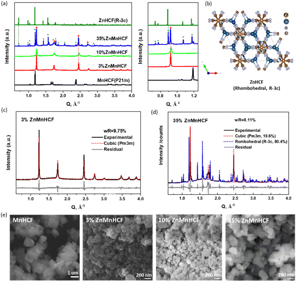 | ||
| Fig. 1 (a) X-ray powder diffraction (XRD) patterns of Zn-substituted MnHCF samples, as well as MnHCF and ZnHCF data. (b) Crystal structure of rhombohedral ZnHCF phases. (c) Pawley refinement of 3% ZnMnHCF XRD data with the cubic (Pm3m) phase. (d) Pawley refinement of 35% ZnMnHCF XRD data with the cubic (Pm3m) and rhombohedral (Rc) phases. (e) SEM images of pure MnHCF, 3% ZnMnHCF, 10% ZnMnHCF and 35% ZnMnHCF. | ||
The cyanide bridge is extremely sensitive to its surrounding chemical environment and bond strength.32 To check the variations in the –CN– coordination environment for all Zn-substituted MnHCF samples, ATR-FTIR spectra were collected, as shown in Fig. S2.† For the MnHCF powder sample, a strong sharp peak at 2066 cm−1 was observed, which is attributed to the stretching vibration ν(CN) of the FeII-CN-MnII group.33 For the 3% ZnMnHCF and 10% ZnMnHCF, the ν(CN) peak appeared at 2069 cm−1, which is a little bit higher than the ν(CN) of the MnHCF sample. However, when the Zn content increased to 35%, the peak at 2069 cm−1 became asymmetric, and a broad shoulder at 2099 cm−1 was formed. The same phenomenon also occurred in the low wavenumber region, where a peak at 493 cm−1 was evidently observed for 35% ZnMnHCF. Based on literature reports,34 the peaks at 2099 cm−1 and 493 cm−1 can be ascribed to the ν(CN) peak and ν(FeC) of the –Zn–NC–FeII– group, respectively, which is consistent with the XRD results of the ZnHCF (Rc) phase for 35% ZnMnHCF.
To further understand the local configuration changes in Fe and Mn sites in the MnHCF framework, as well as the local coordination states of substituted Zn in all the ZnMnHCF samples, Fe, Mn and Zn K-edge XAS data were collected. As shown in Fig. S3,† none of the Zn-substituted MnHCF samples exhibit any obvious changes in the Fe K-edge, neither at the pre-edge region nor at the edge, or generally, in the full X-ray Absorption Near Edge Structure (XANES) spectra. This indicates that the oxidation states and local coordination geometry of the Fe center are retained with increasing Zn content. This conclusion is further extended to the Fe local structural arrangement by looking at the corresponding Fourier transform (FT) of the k2-weighted Extended X-ray Absorption Fine Structure (EXAFS) signal of the Fe K-edge, which exhibits only a small variation in the peak intensity in the first and second shell due to structural disorder effects and a more significant difference in the third shell, which most likely can be ascribed to the substitution of Mn by Zn in the –Fe–C–N–Mn (Zn)– structural fragment.
For the Mn K-edge, a slight difference was observed at the pre-edge region, at 6546.5 eV (Fig. 2a), as well as in the edge peak intensity (white-line) and the first peak of the FT of the k2-weighted EXAFS (Fig. 2c), which was as expected, considering the local changes at Mn sites. The detail of the local structure of the Mn site was obtained from the EXAFS fitting results, as given in Fig. 2d, e and S4.† Similar to the octahedral coordination of Mn in the MnHCF sample, Mn in all the Zn-substituted MnHCF samples retained the same octahedral coordination states, but their structures were distorted. As illustrated in Fig. 2f, g and Table S2,†e.g. for 10% ZnMnHCF, the four equatorial Mn–N distances lengthened to 2.25 Å, and the two axial Mn–N distances remained almost the same at 2.19 Å, evidencing local structural asymmetry. Therefore, XRD and local structural changes of the Mn sites provided by XAS indicate that the substitution of Zn on the framework introduces long-range and short-range structural modifications.
 | ||
| Fig. 2 (a) XANES spectra of Mn K-edge of the Zn-substituted MnHCF samples and pure MnHCF sample. (b) k2-Weighted EXAFS signals and (c) corresponding Fourier transform (FT) of the k2-weighted EXAFS signals of the Mn K-edge. EXAFS analysis of the Mn K-edge of (d) MnHCF and (e) 10% ZnMnHCF samples, each panel of the figure shows individual EXAFS contributions, in terms of two-body, three-body and four-body signals, to the total theoretical signal. The Mn–N bond distances of (f) MnHCF and (g) 10% ZnMnHCF samples. | ||
To check the detailed coordination states of Zn within the Zn-substituted samples, pure ZnHCF (Rc) Zn K-edge data were collected, as shown in Fig. 3a. As observed, all the Zn-substituted samples share the same XANES pattern compared with ZnHCF, which is characterized by the presence of a shoulder in the rising part of the edge at 9662.7 eV and a white line at 9669.0 eV, which is observed in the tetrahedral coordination state of Zn2+.35,36 Owing to the low Zn content in the 3% ZnMnHCF sample, the k2-weighted EXAFS signal appears noisy (Fig. 3b), and the FT of the k2-weighted EXAFS signal exhibits three peaks, as expected for this material (Fig. 3c). The coordination states of Zn were studied using the EXAFS fitting data, as displayed in Fig. 3d, e and S5.† The fitting was based on tetrahedrally coordinated Zn configuration, as shown in Fig. 3f, and the coordination number of the first shell (Zn–N) is 4. The detail of the fitting outcomes is listed in Table S3.† In contrast, from the Zn 2p3/2 X-ray Photoelectron Spectroscopy (XPS) data, a different chemical state was observed between the 3% ZnMnHCF/10% ZnMnHCF and 35% ZnMnHCF samples. The fitting results show that for the 3% ZnMnHCF and 10% ZnMnHCF samples, two peaks at 1021 eV and 1023 eV are observed, which can be attributed to the coordination states of Zn–N and Zn–OH/H2O, respectively.37–40 In comparison, for 35% ZnMnHCF, the peak at 1021 eV became the dominant peak, with a small peak at 1018.8 eV, which can be attributed to Zn–O vacancies or Zn–O–metal.41,42 As indicated by the XRD data, a rhombohedral ZnHCF phase was formed by 35% ZnMnHCF, in which Zn is mainly tetrahedrally coordinated to 4 N from –NC– ligands, same as the ZnHCF powder XPS data (Fig. S6†). Based on the XAS and XPS results, it is concluded that the local configuration of Zn in Zn-substituted MnHCF samples of 35% ZnMnHCF corresponds to the one of the ZnHCF framework (tetrahedrally coordinated), while the coordination atoms of 3% ZnMnHCF and 10% ZnMnHCF might also include the O from H2O.
 | ||
| Fig. 3 (a) XANES spectra of Zn K-edge of Zn-substituted MnHCF samples and pure ZnHCF sample. (b) k2-Weighted EXAFS signals, as well as (c) corresponding Fourier transform (FT) of k2-weighted EXAFS signal of Zn K-edge. EXAFS analysis of Zn K-edge of (d) ZnHCF and (e) 10% ZnMnHCF samples. (f) The tetrahedral coordination of Zn sites. Zn 2p3/2 XPS data of (g) 3% ZnMnHCF, (h) 10% ZnMnHCF and (i) 35% ZnMnHCF samples. | ||
The CV measurements of MnHCF and Zn-substituted samples were performed at 0.2 mV s−1 over the potential window of 1.0–2.0 V vs. Zn/Zn2+. The evolution of redox peaks is clearly illustrated in Fig. 4a–d and S7.† During the first 10 cycles, 3% ZnMnHCF and 10% ZnMnHCF exhibited similar changes in redox peaks, especially the newly formed cathodic peaks at around 1.21 V and 1.36 V, which were not as obvious for the 35% ZnMnHCF electrode. The evolution of the redox peaks indicates that with intercalation of Zn2+, the chemical composition and phase structure of the electrodes also changed, as demonstrated in our previous report,29 which can be illustrated by eqn (1). Unlike the MnHCF electrode, in the first 10 cycles, the changes in redox peaks of all the Zn-substituted samples are relatively small. While, after 10 cycles, both MnHCF and the entire series of Zn-substituted MnHCF electrodes reached a relatively stable state, the peak positions remained unchanged, but the peak current intensity was slightly altered. The area of CV curves is proportional to the charge of the cathode material. As depicted in Fig. 4e, the specific capacity of all the Zn-substituted MnHCF samples decreased with increasing Zn content. However, unlike the behavior displayed by the MnHCF sample (Fig. 4f), which is characterized by persistent capacity fading after 20 cycles, the cycling stability of the Zn-substituted samples is found to be better, with a good steady state behavior seen for 10% ZnMnHCF. Moreover, it exhibited the highest rate capability (Fig. S7e†), and it will be the focus of a detailed analysis. Thus, to better understand the different working mechanisms of Zn-substituted MnHCF in AZIBs, the 10% ZnMnHCF electrode was selected, and its structural evolution during the charge/discharge process was monitored using synchrotron X-ray techniques.
| ZnxMnHCF + (y + z)Zn2+ + 2ze− ↔ ZnzZnx+yMn1−yHCF + yMn2+ | (1) |
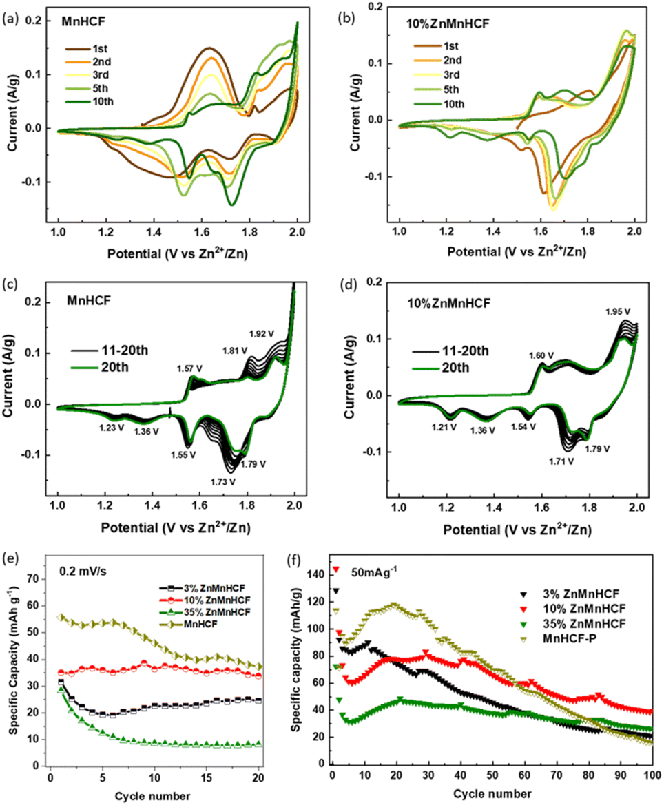 | ||
| Fig. 4 CV data of (a and c) MnHCF and (b and d) 10% ZnMnHCF in the 3 M ZnSO4 electrolyte at 0.2 mV s−1 for 20 cycles. (e) The specific capability calculated based on CV data. (f) Cycling stability of Zn-substituted MnHCF samples at 50 mA g−1. | ||
2.2 Structural evolution of 10% ZnMnHCF
To understand the local structural change of the metal sites in the 10% ZnMnHCF electrode during the charge/discharge process, ex situ XAS data at Fe, Mn and Zn K-edges were recorded for the cycled electrodes (C1, D1 and C2). As displayed in Fig. S8,† the Fe K-edge XANES data for C1, D1 and C2 electrodes are different from the 10% ZnMnHCF powder data, not only in the intensity of the white line, but also in the suppression of resonance at around 7150 eV. The intensity of the white line in all cycled electrodes decreased, as it happened for the first two peaks of the FT of the k2-weighted EXAFS signal (related to the Fe–C and Fe–C–N interactions), and this can be explained by the increasing structural disorder,43 which is the quantified Debye–Waller factor in EXAFS data analysis (see Table S4†). Another expected difference was observed in the third peak, which, in principle, should correspond to the Zn and Mn sites, based on the framework of Fe–CN–Mn/Fe–CN–Zn. All the cycled electrodes exhibited a peak at around 4.1 Å, which overlapped with the ZnHCF Fe K-edge data.The part that attracted our attention was the Mn K-edge data. As displayed in Fig. 5a–c, unlike the pristine 10% ZnMnHCF sample, all the cycled electrodes exhibited an identical XANES spectral feature and FT peaks, indicating that there was a strong local structural change at the Mn sites during the initial cycling and this new structural arrangement remains stable in the following cycles, regardless of the charge or discharged state of the electrode. This observation is different from the previous report on the MnHCF sample,29 and a stable change on the Mn site is observed after the 1st charge cycle. To evaluate the structural alteration at Mn sites in detail, a Linear Combination Fitting (LCF) analysis of the normalized XANES of C1, D1 and C2 electrodes with standard Mn-based oxides was conducted (Fig. 5d and S9†). Fitting results exhibit that the linear combination of MnO2, Mn2O3 and Mn3O4 compounds fit well with all the cycled electrodes, and the percentage of each component is shown in Fig. 5e. Based on the LCF analysis, a rough estimation of the oxidation state of Mn at C1, D1 and C2 states was calculated (Fig. 5e), and the valence of Mn changed from 3.4 (C1) to 3.1 (D1), then to 3.3 (C2), which is a close value (in the limitation of the present approach) to the formal oxidation state of 4+ for Mn in MnO2. A further comparison of MnO2 and C1 electrodes, in terms of the FT of the Mn k2-weighted EXAFS signal, reveals a complete match of the two curves (Fig. 5f). Therefore, the two structures must be closely similar. To obtain more quantitative local structural information on the Mn site, EXAFS analysis is required. As observed in Fig. S10a,† the 10% ZnMnHCF_C1 electrode was first fitted with the distorted MnHCF model.10 Although this model well fitted the 10% ZnMnHCF electrode, it failed to fit the cycled electrodes. This is not surprising, based on the discussion above and a previous report on the parametrization of the fitting procedure.29 A two-model fitting, based on the distorted MnHCF (Mn–6N–) and MnO2 (Mn–6O–) models, was conducted on the C1, D1 and C2 electrodes, as displayed in Fig. 5g, h, S10b and c.† The agreement between the theoretical and experimental data is significantly better compared with the single model-fitting results. This newly formed stable Mn configuration (mixed MnO2 and MnHCF local environment) could partly explain the high cycling stability of the 10% ZnMnHCF electrode.
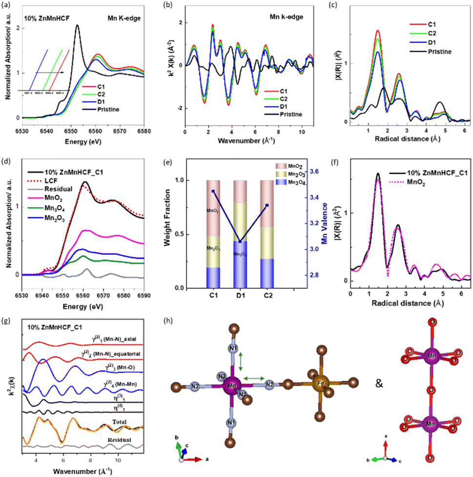 | ||
| Fig. 5 (a) Ex situ XANES of the Mn K-edge at different charge/discharge states (C1: 1st charge, D1: 1st discharge and C2: 2nd charge states). (b) k2-Weighted EXAFS signals and (c) corresponding Fourier transform (FT) of the Mn k2-weighted EXAFS signal. (d) Linear combination fitting (LCF) of the normalized Mn K-edge XANES spectra of 10% ZnMnHCF_C1. (e) The LCF result of Mn K-edge of 10% ZnMnHCF_C1/D1/C2 samples. (f) Comparison of Mn k2-weighted EXAFS FT peaks of the 10% ZnMnHCF_C1 electrode and MnO2. (g) EXAFS fitting results of 10% ZnMnHCF_C1 based on two models (MnHCF and MnO2); each panel of the figure shows the individual EXAFS contributions in terms of distorted two-body, three-body and four-body signals. (h) The coordination state of the Mn–6N– bond from the MnHCF model and Mn–6O– bond from the MnO2 model. | ||
The local configuration change in Zn sites in the 10% ZnMnHCF electrode during cycling was also checked from the Zn K-edge XAS data. As shown in Fig. 6a–c, slightly different XANES spectra were observed for the cycled and pristine electrodes, especially for the rising portion of the spectrum at 9662.7 eV and the white line at 9669.3 eV. According to a report by Kuzmin et al.,35 a similar XANES pattern (with two peaks) was observed for ZnO with a larger cluster size, whereas a single XANES edge peak was observed for ZnO with a smaller cluster size. They explained that the difference is due to the distribution of electron density around the Zn atom, i.e. smaller cluster Zn contains a strongly anisotropic ZnO4 tetrahedron. Besides, increasing the number of shells results in the average distribution of electron density becoming more isotropic. Thus, it might be considered that for the pristine 10% ZnMnHCF electrodes, the electron density around Zn is more isotropic than in the cycled electrodes. For 10% ZnMnHCF_D1 and 10% ZnMnHCF_D2 electrodes, the shoulder peak at around 9662.7 eV almost disappeared (Fig. 6c).
 | ||
| Fig. 6 Ex situ XANES of (a) the Zn K-edge and (b and c) zoom-in of the Zn K-edge XANES. EXAFS fitting results at Zn K-edge for (d) 10% ZnMnHCF_C1 based on a tetrahedral coordination of Zn sites, with 3 N from –NC– ligands and 1 O from H2O and (e) 10% ZnMnHCF_C2 electrodes, based on an octahedral coordination of Zn sites, with 4 N from –NC– ligands and 2 O from H2O. | ||
To obtain more relevant local structural information around Zn, an EXAFS fitting was conducted. For the charged electrodes, i.e. 10% ZnMnHCF_C1 and 10% ZnMnHCF_C2 electrodes, based on the above discussion of Zn XAS and XPS data, EXAFS fitting was carried out by testing two different models: tetrahedral coordinated Zn with 4 N from –CN– ligands (Zn–4N) and tetrahedral coordinated Zn with 3 N from –NC– ligands and one O from H2O (Zn–3N–O) (Fig. 6d and S11†). The best fit was observed for the Zn–3N–O model, with a possibly decreasing electron density isotropy, which aligns with the above-observed XANES shoulder behavior. On the contrary, the tetrahedral model was unsuitable for the discharged (Zn2+ insertion) 10% ZnMnHCF_D1 electrode, with a high residual value, as shown in Fig. S12 and Table S6.† Based on the reports on structure transformation of ZnHCF with temperature,44,45 a tetrahedral to octahedral local coordination change in Zn in an aqueous electrolyte upon zinc ion intercalation was proposed. The coordination environment of Zn consists of 4 N atoms from –NC– ligands plus 2 O from H2O (Zn–4N–2O). We have therefore verified our hypothesis by performing a new EXAFS fitting of the 10% ZnMnHCF_D1 electrode using the octahedral model, as displayed in Fig. 6e. The residual value significantly decreased with respect to the tetrahedral model, and a distorted octahedral configuration with 4 Zn–N bonds around 1.94 Å and two Zn–O bonds around 2.06 Å was obtained. However, by considering a more discharged electrode (after 20 cycles), the corresponding EXAFS signal exhibits a better fitting result (a lower residual index) with the Zn–3N–O model (Fig. S13†), similar to the charged electrodes. Having clarified the local atomic changes in Mn and Zn during zinc ion insertion and release, we need to further understand the changes in the long-range crystalline structure triggered by zinc intercalation.
We therefore monitored the crystal structure evolution of 10% ZnMnHCF upon the intercalation of Zn2+ by adopting synchrotron ex situ and operando XRD. As displayed in Fig. 7a, the ex situ XRD data at the C1, D1, D2, D10, D20 and D100 states were collected. After the 1st charging (C1), the original 10% ZnMnHCF peaks totally disappeared, and multiple new peaks were formed. The detailed evolution of the 1st cycle is illustrated in Fig. 7b during an operando scan. Compared with the 10% ZnMnHCF powder XRD peaks, the initial XRD peaks (before 1st charging) already shifted slightly towards the low 2θ value, which indicates the start of the modification upon the soaking of the electrodes with the electrolyte. During the 1st charging cycle (before charged to 1.8 V), all the XRD peaks were stable. After charging to 1.8 V, the peak at 1.14 Å−1 gradually decreased and changed into two peaks at 1.09 Å−1 and 1.13 Å−1. The signal at 1.62 Å−1 became broad, and the peak at approximately 2.30 Å−1 disappeared. Furthermore, multiple new peaks were formed. In principle, all these modifications happened during the oxidation of the Mn process and remained unchanged throughout the entire discharge process.17,46 Pawley refinement was conducted on the XRD data of the C1, D1 and D20 electrodes (Fig. 7c–e), and the results indicate that the pristine cubic phase of 10% ZnMnHCF transformed into a rhombohedral phase at the end of the C1 process and subsequently changed to a monoclinic phase at the end of D1 process. However, how the long-range order outcome is influenced by the local atomic structural observation at Mn and Zn mentioned above is unclear. The D1, D2 and D10 electrodes exhibited quite similar XRD patterns. However, after 20 cycles, the XRD data changed, and D20 and D100 shared the same pattern. As observed in Fig. 7f, all the Zn-substituted samples exhibited the same XRD result after 100 cycles, which is the same XRD data we reported for the cycled “undoped” MnHCF electrodes in the 3 M ZnSO4 electrolyte.29 However, for 10% ZnMnHCF, Zn-substitution increases the symmetry of the pristine MnHCF structure, and the Mn site experienced rapid and steady changes at the initial charge cycle, which partly explains the higher cycling stability of 10% ZnMnHCF electrodes, as given in Fig. 4. Eventually, after long-term cycling, the final phase for the “undoped” MnHCF and Zn-substituted MnHCF samples in aqueous ZnSO4 is seen to be the same, forming a unified ZnHCF cubic phase, as illustrated in Fig. 7g, with Zn tetrahedrally coordinated with the –N3O model. Based on the above analysis, the phase transformation of 10%ZnMnHCF during cycling is illustrated in Fig. 7h.
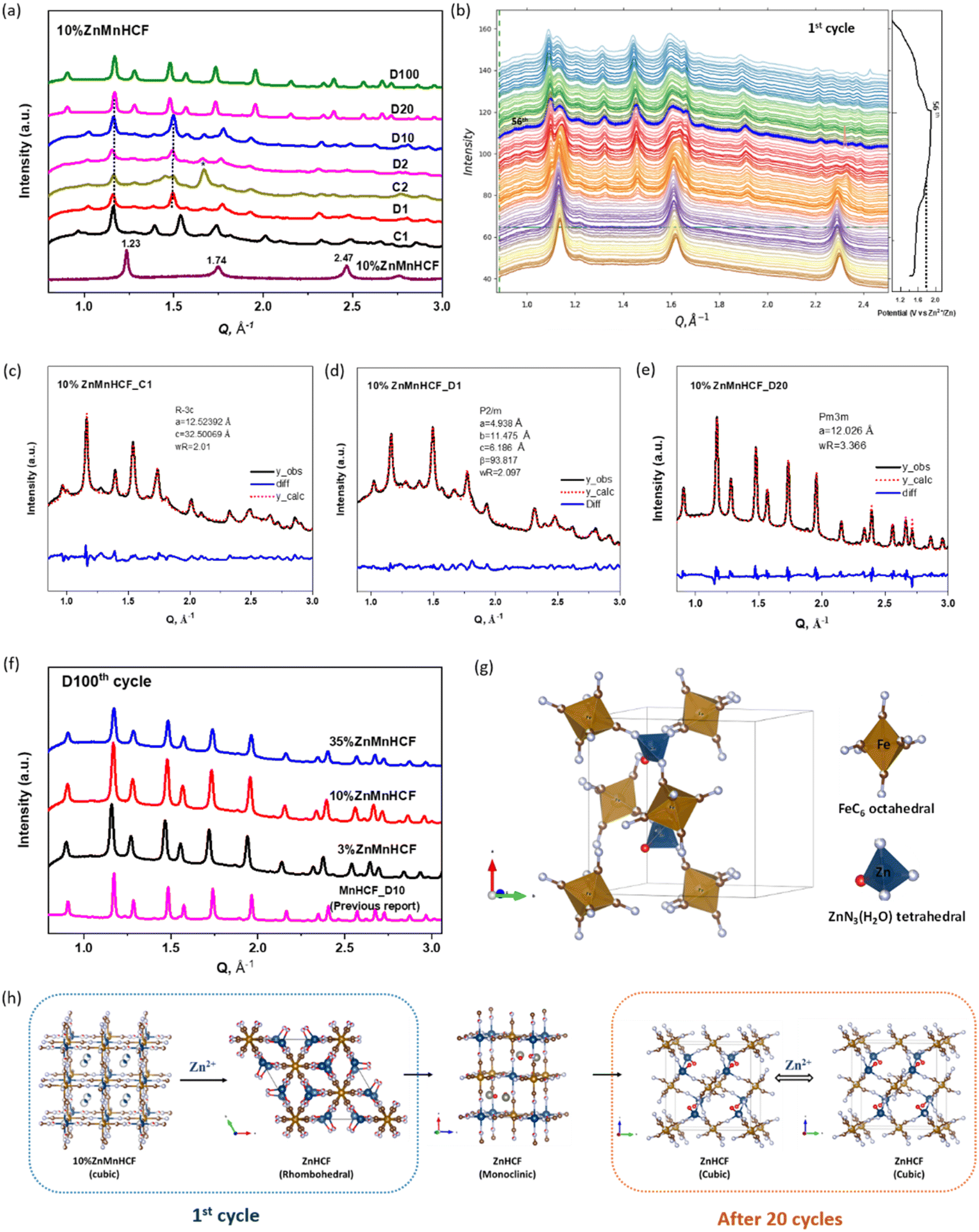 | ||
| Fig. 7 (a) Ex situ synchrotron XRD data of MnHCF electrode at different charge/discharge states (10% ZnMnHCF powder, C1, D1, D2, D10, D20 and D100 electrodes). (b) Operando synchrotron XRD data of the 1st cycle. (c–e) Pawley refinement of 10% ZnMnHCF_C1, 10% ZnMnHCF_D1 and 10% ZnMnHCF_D20 electrodes. (f) XRD data of the 100th discharge (D100) of 3% ZnMnHCF, 10% ZnMnHCF and 35% ZnMnHCF electrodes, as well as the D10 electrode of MnHCF in 3 M ZnSO4. (g) The atomic packing within the unit cell of Zn2[Fe (CN)6], where Zn atom has a tetrahedral coordination to 3 N ends and 1 H2O molecule. (h) Schematic illustration of the crystal structure transformation of 10% ZnMnHCF during the first and after 20 cycles. | ||
3 Conclusions
In summary, a series of Zn-substituted MnHCF cathode materials were synthesized for AZIBs. The synchrotron XRD and XAS data show that Zn substitution reorganized the crystal structure of the MnHCF framework and changed the local structural arrangement of Mn sites. Furthermore, 3% and 10% Zn substitutions were able to relieve the original distortion of the monoclinic MnHCF structure. When Zn content was increased to 35%, a ZnHCF rhombohedral phase was formed, and a mixed structure of cubic and rhombohedral phases coexisted. Although lower specific capacity was observed for all Zn-substituted electrodes, better cycling stability, i.e., a flat line behavior, particularly for 10% ZnMnHCF, was obtained. This is good for the eventual upscale of the process and electrode fabrication. An in-depth study of the intercalation mechanism of the 10% ZnMnHCF electrode showed a coherent structure–activity relationship as the local structural change of the Mn site is closely related to the electrochemical performance of the 10% ZnMnHCF electrode. The newly formed Mn–6O– local atomic framework after the first charge cycle was stabilized during the cycling. Upon the intercalation of Zn2+, the configuration of Zn changed from a tetrahedral coordinated state (C1) to an octahedral state (D1). After 20 cycles, only the tetrahedral coordinated state was observed, which is consistent with the XRD result. In the end, all Zn-substituted samples share the same cubic ZnHCF structure after 100 cycles. This research not only provides the detailed structure–property–performance relationship of a Zn-substituted MnHCF system in an aqueous ZnSO4 electrolyte, but also offers a comprehensive understanding of the MnHCF-based AZIB system. There has always been a trade-off between structural stability and capacity. However, the structural data reported for the 10% doped sample indicate that there is room for improvement in the electrochemical data, and the structure may adapt to the modification induced by zinc ion insertion and release during an electrochemical reaction.Data availability
The data that support the findings of this study are available from the corresponding author upon reasonable request.Author contributions
Min Li: review & editing, writing – original draft, methodology, investigation, formal analysis, data curation, and conceptualization. Mariam Maisuradze: review & editing, data curation, and XPS characterization. Zulkarnaen Paputungan: review & editing and SEM characterization. Reinhard Denecke: review & editing and XPS characterization. Jasper Rikkert Plaisier: synchrotron XRD characterization. Giuliana Aquilanti: synchrotron XAS characterization. Giovanni Agostini: review & editing and synchrotron XAS characterization. Marco Giorgetti: review & editing, supervision, resources, project administration, conceptualization, and funding acquisition.Conflicts of interest
There are no conflicts to declare.Acknowledgements
Measurements at Elettra were supported by CERIC project # 20212162 (M. G. as PI) and ELETTRA project 20230452 (MG as PI). Work was also supported by the RFO funds of the University of Bologna. MUR is acknowledged for the partial support through the Sustainable Mobility Center, Centro Nazionale per la Mobilità Sostenibile – CNMS, Spoke 6 of the National Recovery and Resilience Plan (NRRP). ENEA-MASE (Ministero dell’Ambiente e della Sicurezza Energetica) is also acknowledged through the Piano Triennale di Realizzazione (2022–2024). The foundation of “Toso Montanari” is acknowledged for funding the internship covering the XPS measurement. The funding of KNOWSKITE-X (ID: 101091534) is acknowledged for the post-doc research of Min Li at the Elettra XAFS beamline.Notes and references
- Z. Jia, B. Wang and Y. Wang, Mater. Chem. Phys., 2015, 149, 601–606 CrossRef.
- G. Zampardi and F. La Mantia, Curr. Opin. Electrochem., 2020, 21, 84–92 CrossRef CAS.
- Y. Li, J. Zhao, Q. Hu, T. Hao, H. Cao, X. Huang, Y. Liu, Y. Zhang, D. Lin, Y. Tang and Y. Cai, Mater. Today Energy, 2022, 29, 101095 CrossRef CAS.
- M. Li, M. Maisuradze, R. Sciacca, I. Hasa and M. Giorgetti, Batteries Supercaps, 2023, 6, e202300340 CrossRef CAS.
- T. Yimtrakarn, Y. C. Liao, A. S. MV, J. L. Chen, Y. C. Chuang, N. Lerkkasemsan and W. Kaveevivitchai, Mater. Today Commun., 2023, 34, 105231 CrossRef CAS.
- L. Wang, Y. Lu, J. Liu, M. Xu, J. Cheng, D. Zhang and J. B. Goodenough, Angew. Chem., Int. Ed., 2013, 52, 1964–1967 CrossRef CAS PubMed.
- Z. Hou, X. Zhang, X. Li, Y. Zhu, J. Liang and Y. Qian, J. Mater. Chem. A, 2017, 5, 730–738 RSC.
- J. Song, L. Wang, Y. Lu, J. Liu, B. Guo, P. Xiao, J. J. Lee, X. Q. Yang, G. Henkelman and J. B. Goodenough, J. Am. Chem. Soc., 2015, 137, 2658–2664 CrossRef CAS PubMed.
- H. Gao, L. Xue, S. Xin and J. B. Goodenough, Angew. Chem., Int. Ed., 2018, 57, 5449–5453 CrossRef CAS PubMed.
- A. Mullaliu, J. Asenbauer, G. Aquilanti, S. Passerini and M. Giorgetti, Small Methods, 2020, 4, 1900529 CrossRef CAS.
- A. Mullaliu, G. Aquilanti, P. Conti, M. Giorgetti and S. Passerini, ChemSusChem, 2020, 13, 608–615 CrossRef CAS PubMed.
- M. Li, R. Sciacca, M. Maisuradze, G. Aquilanti, J. Plaisier, M. Berrettoni and M. Giorgetti, Electrochim. Acta, 2021, 400, 139414 CrossRef CAS.
- W. Deng, Z. Li, Y. Ye, Z. Zhou, Y. Li, M. Zhang, X. Yuan, J. Hu, W. Zhao, Z. Huang, C. Li, H. Chen, J. Zheng and R. Li, Adv. Energy Mater., 2021, 11, 2003639 CrossRef CAS.
- T. Cao, F. Zhang, M. Chen, T. Shao, Z. Li, Q. Xu, D. Cheng, H. Liu and Y. Xia, ACS Appl. Mater. Interfaces, 2021, 13, 26924–26935 CrossRef CAS PubMed.
- G. Ni, Z. Hao, G. Zou, X. Xu, B. Hu, F. Cao and C. Zhou, Sustainable Energy Fuels, 2022, 6, 1353–1361 RSC.
- D. Yang, J. Xu, X. Z. Liao, Y. S. He, H. Liu and Z. F. Ma, Chem. Commun., 2014, 50, 13377–13380 RSC.
- M. Pasta, R. Y. Wang, R. Ruffo, R. Qiao, H. W. Lee, B. Shyam, M. Guo, Y. Wang, L. A. Wray, W. Yang, M. F. Toney and Y. Cui, J. Mater. Chem. A, 2016, 4, 4211–4223 RSC.
- Y. Moritomo, S. Urase and T. Shibata, Electrochim. Acta, 2016, 210, 963–969 CrossRef CAS.
- M. A. Oliver-Tolentino, J. Vázquez-Samperio, S. N. Arellano-Ahumada, A. Guzmán-Vargas, D. Ramírez-Rosales, J. A. Wang and E. Reguera, J. Phys. Chem. C, 2018, 122, 20602–20610 CrossRef CAS.
- X. Bie, K. Kubota, T. Hosaka, K. Chihara and S. Komaba, J. Power Sources, 2018, 378, 322–330 CrossRef CAS.
- M. Oliver-Tolentino, M. González, H. Osiry, G. Ramos-Sánchez and I. González, Dalton Trans., 2018, 47, 16492–16501 RSC.
- Z. Xu, Y. Sun, J. Xie, Y. Nie, X. Xu, J. Tu, C. Shen, Y. Jin, Y. Li, Y. Lu, A. Zhou, F. Chen, T. Zhu and X. Zhao, Mater. Today Sustainability, 2022, 18, 100113 CrossRef.
- D. A. El-Hady, Y. Lyu, S. Zhan, J. Yang, Y. Wang, F. Yang, Q. Zhao, M. Gu and M. Shao, SSRN Electron. J., 2022, 1–18 Search PubMed.
- J. Beitia, I. Ahedo, J. I. Paredes, E. Goikolea and I. Ruiz de Larramendi, Nanomaterials, 2024, 14, 1092 CrossRef CAS PubMed.
- W. A. Syed, A. K. Kakarla, H. Bandi, R. Shanthappa and J. S. Yu, J. Energy Storage, 2024, 99, 113325 CrossRef.
- Y. Zeng, X. F. Lu, S. L. Zhang, D. Luan, S. Li and X. W. Lou, Angew. Chem., Int. Ed., 2021, 60, 22189–22194 CrossRef CAS PubMed.
- Y. Zeng, J. Xu, Y. Wang, S. Li, D. Luan and X. W. (David) Lou, Angew. Chem., 2022, 48, e202212031 Search PubMed.
- G. Yang, Z. Liang, Q. Li, Y. Li, F. Tian and C. Wang, ACS Energy Lett., 2023, 8, 4085–4095 CrossRef CAS.
- M. Li, M. Maisuradze, A. Mullaliu, I. Carlomagno, G. Aquilanti, J. R. Plaisier and M. Giorgetti, Small, 2024, 51, 2404584 CrossRef PubMed.
- J. Kim, S. H. Yi, L. Li and S. E. Chun, J. Energy Chem., 2022, 69, 649–658 CrossRef CAS.
- M. Li, M. Gaboardi, A. Mullaliu, M. Maisuradze, X. Xue, G. Aquilanti, J. R. Plaisier, S. Passerini and M. Giorgetti, ChemSusChem, 2023, 16, e202300201 CrossRef CAS PubMed.
- J. Lejeune, J. B. Brubach, P. Roy and A. Bleuzen, C. R. Chim., 2014, 17, 534–540 CrossRef CAS.
- S. Goberna-Ferrón, W. Y. Hernández, B. Rodríguez-García and J. R. Galán-Mascarós, ACS Catal., 2014, 4, 1637–1641 CrossRef.
- J. Rodríguez-Hernández, E. Reguera, E. Lima, J. Balmaseda, R. Martínez-García and H. Yee-Madeira, J. Phys. Chem. Solids, 2007, 68, 1630–1642 CrossRef.
- A. Kuzmin, S. Larcheri and F. Rocca, J. Phys.: Conf. Ser., 2007, 93, 2–8 CrossRef.
- A. Rodrigues, M. do Carmo Martins Alves and J. Morais, Mater. Des., 2018, 142, 240–246 CrossRef CAS.
- F. Yang, P. Song, X. Liu, B. Mei, W. Xing, Z. Jiang, L. Gu and W. Xu, Angew. Chem., Int. Ed., 2018, 57, 12303–12307 CrossRef CAS PubMed.
- X. Z. Zhai, J. Qu, S. M. Hao, Y. Q. Jing, W. Chang, J. Wang, W. Li, Y. Abdelkrim, H. Yuan and Z. Z. Yu, Nano-Micro Lett., 2020, 12, 1–15 CrossRef PubMed.
- W. Deng, S. Min, F. Wang, Z. Zhang and C. Kong, Dalton Trans., 2020, 49, 5434–5439 RSC.
- A. Cano, L. Lartundo-Rojas, A. Shchukarev and E. Reguera, New J. Chem., 2019, 43, 4835–4848 RSC.
- P. Kumar, M. C. Mathpal, G. K. Inwati, S. Kumar, M. M. Duvenhage, W. D. Roos and H. C. Swart, Magnetochemistry, 2023, 9, 20 CrossRef CAS.
- P. Kumar, A. Kumar, M. A. Rizvi, S. K. Moosvi, V. Krishnan, M. M. Duvenhage, W. D. Roos and H. C. Swart, Appl. Surf. Sci., 2020, 514, 145930 CrossRef CAS.
- G. Aquilanti, M. Giorgetti, R. Dominko, L. Stievano, I. Arčon, N. Novello, L. Olivi, I. Ar, N. Novello, L. Olivi, I. Arčon, N. Novello and L. Olivi, J. Phys. D Appl. Phys., 2017, 50, 074001 CrossRef.
- C. P. Krap, B. Zamora, L. Reguera and E. Reguera, Microporous Mesoporous Mater., 2009, 120, 414–420 CrossRef CAS.
- J. Ding, C. W. Ng and Y. Shi, IEEE Trans. Magn., 2001, 37, 2938–2940 CrossRef CAS.
- Q. Li, K. Ma, G. Yang and C. Wang, Energy Storage Mater., 2020, 29, 246–253 CrossRef.
Footnote |
| † Electronic supplementary information (ESI) available: Experimental section, ESI figures and tables. See DOI: https://doi.org/10.1039/d4ta08889a |
| This journal is © The Royal Society of Chemistry 2025 |