
 Open Access Article
 This Open Access Article is licensed under a
 Creative Commons Attribution 3.0 Unported Licence
Effects of electrolyte, state of charge, and strain rate on the mechanical properties of lithium-ion battery electrodes and separators†
Shuguo Sunab,
Bo Ruiab,
Xijun Tanab,
Saurabh Bahugunac,
Jun Zhouc and
Jun Xu *ab
*ab
aDepartment of Mechanical Engineering, University of Delaware, Newark, DE 19716, USA. E-mail: junxu@udel.edu
bEnergy Mechanics and Sustainability Laboratory (EMSLab), University of Delaware, Newark, DE 19716, USA
cGeneral Motors, Detroit, MI 48232, USA
First published on 16th May 2025
Abstract
The mechanical properties of electrode materials are critical to the mechanical, electrical, and thermal performance, safety, and durability of lithium-ion batteries (LIBs). While mechanical testing is often conducted to elucidate the fundamental behavior of electrode materials, most existing studies focus on dry electrodes, which fail to fully capture the in-cell conditions. To address this gap, this study provides a comprehensive investigation of the coupled effects of SOC, electrolyte, and strain rate on the mechanical behavior of cathodes and anodes through compression and tensile testing. The study begins by isolating the impacts of SOC and electrolyte individually, followed by an analysis of their coupling effects. Scanning electron microscopy (SEM) characterization under diverse conditions is employed to uncover the underlying mechanisms driving these behaviors. Results reveal that the interplay between SOC, electrolyte presence, and strain rate significantly influences the mechanical responses of electrodes. These findings offer critical insights into the behavior of battery components under realistic loading conditions, demonstrating the complexity of the coupling of solid–liquid interactions in porous materials and providing a foundation for improving the evaluation and design of LIB safety and durability.
1 Introduction
Lithium-ion batteries (LIBs) are indispensable to modern automation and energy storage systems due to their exceptional energy efficiency, long lifespan, and high energy density. The announced production of nickel cobalt manganese (NCM) and lithium iron phosphate (LFP) LIBs will reach unprecedented levels of 10![[thin space (1/6-em)]](https://www.rsc.org/images/entities/char_2009.gif) 000 GW h by 2030.1 This rapid growth, particularly in applications such as electric vehicles (EVs) and aviation, has heightened concerns over safety.2 LIBs subjected to mechanical abuse are susceptible to internal short circuits (ISCs),3 which can lead to irreversible thermal runaway, accompanied by fire or explosions. Thus, understanding the mechanical properties and failure mechanisms of battery components is critical for ensuring the safety and reliability of LIBs.
000 GW h by 2030.1 This rapid growth, particularly in applications such as electric vehicles (EVs) and aviation, has heightened concerns over safety.2 LIBs subjected to mechanical abuse are susceptible to internal short circuits (ISCs),3 which can lead to irreversible thermal runaway, accompanied by fire or explosions. Thus, understanding the mechanical properties and failure mechanisms of battery components is critical for ensuring the safety and reliability of LIBs.
The state of charge (SOC) of a battery, representing the amount of charge stored, directly influences the mechanical properties of LIBs.4 During charging, lithium-ion deintercalation from the cathode and intercalation into the anode alters the mechanical behavior of battery components. Extensive studies have focused on the relationship between SOC and mechanical properties.5–7 At the electrode material (battery component material) level, Huang et al.8 investigated the lithiation induced fracture mechanisms using single-walled carbon nanotubes. Wang et al.9 examined the coupled effects of SOC on the mechanical behavior of graphite anodes through experimental and modeling approaches. Pan et al.10 conducted tensile tests to study the SOC-dependent mechanical properties of cathodes and anodes. In addition, Xu et al.11 pioneered reporting the SOC effects on electrodes and separators using compression and tensile tests. At the cell level, the primary focus is on mechanical failure and the resulting internal short circuit. Jia et al.12 revealed the SOC dependency of structural stiffness under dynamic strain rates, while Duan et al.13 established a strong correlation between SOC and stress-induced ISCs. Yiding et al.14 developed an electrochemical–thermal model to uncover the failure mechanisms of cells at various SOCs. Wang et al.15 explored the impact of the SOC on corroded batteries, with a particular focus on extending their findings to applications in marine environments. Li et al.16 conducted mechanical abuse tests to investigate the SOC dependency on batteries with external constraints. These studies highlight the significance of SOC in understanding the mechanical behavior of LIBs across scales.
Simultaneously, the interactions between electrolyte and porous electrode materials have gained increasing attention. Electrolyte effects are primarily attributed to two mechanisms: (1) possible side reactions of electrolytes with active materials and current collectors, and (2) interaction between the electrolyte and material at the microstructure level.17 Currently available studies mainly focus on the macroscopic influence of the electrolyte at the cell level. Kisters et al.18 demonstrated the softening effects of electrolytes on electrode mechanical properties by comparing dynamic loading on dry and wet cells. Dixon et al.19 further advanced this understanding through finite element models simulating electrolyte impact on cell behavior. Gupta et al.20 explored the correlation between the electrolyte and mechanical properties degradation of the electrode on the layer level. Additionally, Gor et al.21 observed the swelling and softening effects of electrolytes on separators by immersing them in various electrolyte solvents. Zhao et al.22 examined electrolyte effects on separators, revealing contrasting trends: the electrolyte induced softening in Celgard 2325 but exhibited a stiffening effect in Celgard PE. Despite these insights, most studies have focused on the entire cell or individual factors, limiting a holistic understanding of mechanical behaviors.
To date, research has primarily investigated the coupling of single factors, such as SOC or electrolyte, with various strain rates, often at the cell level. However, studies on the coupled effects of SOC, electrolyte, and strain rates on individual components (e.g., anodes, cathodes, and separators) remain scarce. Addressing this knowledge gap is essential for a comprehensive understanding of LIB mechanical behavior under realistic operating conditions.
Therefore, this study systematically examines the coupled effects of SOC and electrolyte on the mechanical behaviors of electrodes under varying strain rates (loading speeds). Compression and tensile tests were employed to analyze the mechanical behavior of electrodes and separators under different electrochemical states (SOC) and electrolyte conditions (presence or absence of electrolyte). The mechanisms driving these effects were explored to provide deeper insights into observed phenomena. Additionally, the strain rate effect is coupled with SOC for wet electrodes, offering valuable perspectives on the mechanical behavior of operating batteries.
2 Experimental
2.1 Sample preparation
The anode and cathode materials were obtained by disassembling an NCM/graphite pouch cell (Fig. 1(a)). A battery cycler (Neware BTS4000) was employed to prepare the battery at various SOCs at room temperature. As the initial SOC and capacity information was unavailable, the battery underwent a complete charge–discharge cycle at a 0.1C C-rate to establish 0% SOC. Subsequently, the battery was charged to the target SOC levels of 0%, 20%, and 40% (Fig. 1(b)). The detailed charging and discharging protocols are outlined in Table 1. After achieving the target SOC, the battery was disassembled in an inert environment within a glove box to extract the anode, cathode, and separator samples for subsequent testing. | ||
| Fig. 1 (a) Battery geometry, battery testing machine and control computer. Charging and discharging cycles were performed using a Neware BTS4000 (5V6A) battery testing machine at room temperature. During the cycling process, data on current, voltage, and capacity were recorded and monitored by the control computer. (b) Charging–discharging curve. A complete charging–discharging cycle was conducted prior to charging the battery to the target SOC, ensuring stability and consistency in the battery's state before testing. | ||
| Step number | Operation | Strategies | C-rate |
|---|---|---|---|
| 1 | Discharge | CC | 0.1C |
| 2 | Rest | 1 hour rest | — |
| 3 | Charge | CCCV | 0.1C |
| 4 | Rest | 1 hour rest | — |
| 5 | Discharge | CC | 0.1C |
| 6 | Rest | 1 hour rest | — |
| 7 | Charge | CC | 0.1C |
2.2 Experimental method
For compression tests, electrodes and separators were cut into round samples with a 25.4 mm and 10.0 mm diameter and stacked to form cylindrical specimens (Fig. 2(a)). Stacking compression tests for each component were designed to simulate the actual working conditions of a battery, which features a layered structure in the out-of-plane direction. This approach differs from a purely uniaxial test, providing a more representative assessment of mechanical behavior. Due to differences in the thickness of the electrode and separator,‡ stacking numbers were adjusted: 30 layers for the anode, 40 layers for the cathode, and 320 layers for separators, ensuring less structural effect and sufficient compressive stroke. Compression tests were conducted using a SUNS UTM 5205 universal testing machine (Fig. 2(b)), which has a maximum load capacity of 200 kN and a resolution of 0.5%. The cylindrical samples were placed at the center of the loading plate, and both force and displacement data were recorded. To enhance displacement accuracy, two linear variable differential transformers (LVDTs) were used to track the deformation during testing. | ||
| Fig. 2 (a) Samples for compressive and tensile testing. Specifically, compression test samples were prepared by stacking round electrode pieces layer by layer to form a cylindrical structure. To enhance grip and prevent slippage during testing, white stickers were applied to both sides of each sample to increase friction with the testing apparatus. (b) Compression testing machine. A double-sided Linear Variable Differential Transformer (LVDT) to improve the accuracy of displacement measurements. (c) Tensile testing machine with Digital Image Correlation (DIC) technology to enhance the precision of displacement measurements. (d) Electrolyte ejection and soaking process for wet conditions tests before sample assembly. Electrodes were sealed into ziplock bags to avoid evaporation. | ||
For tensile tests, rectangular samples with a uniform shape (40 mm effective length and 6 mm width) were prepared (Fig. 2(a)). The tests were performed using an Instron 34SC testing machine (Fig. 2(c)), which has a 5 kN maximum load capacity with 0.5% resolution. Strain measurements were obtained using digital image correlation (DIC) technology from Correlated Solutions Inc., which employs an optical method to capture surface deformation patterns during testing. For separators, tensile tests were conducted in both the machine direction (MD) and transverse direction (TD) to account for their anisotropic properties. Samples were fixed at both ends using paper-covered fixtures to increase friction and minimize slippage.
Samples with different SOCs were prepared by disassembling batteries charged to specific SOC levels (Section 2.1). To mimic engineering application scenarios, tests were performed both with and without the electrolyte. For “dry conditions” tests, disassembled materials were kept in an Argon gas environment inside a glove box until thoroughly dried. For “wet conditions” tests, electrodes were sealed in a Ziplock bag and soaked in an electrolyte for 72 hours to ensure saturation (Fig. 2(d)). The electrolyte volume for each sample was calculated based on the cell vendor's specification sheet.  , where Ve,sample denotes the electrolyte volume that is ejected on the sample; Ve,cell is the electrolyte volume of the whole cell, which is provided by the cell provider. Vsample and Vcell are the volume of the sample and cell separately. To prevent potential oxidation of the electrode in air, sample preparation was carried out entirely within a glove box. The testing procedure was designed to be completed within 2 minutes. Under wet conditions, the electrolyte covering the electrode surface acts as a thin protective film, further inhibiting oxidation (Fig. S6†). For separator wet tests, the soaking time was reduced to 20 minutes, as previous studies23 confirmed that soaking time does not significantly affect their mechanical properties. Furthermore, the tests with various strain rates (i.e., 0.001–1 s−1) were designed to investigate the strain rate effect of materials from quasi-static to low strain rate loading, which may have coupling effects with SOC and electrolyte conditions, thus providing a more realistic understanding of materials properties.
Tests were performed at various strain rates (0.001–1 s−1) to evaluate the strain rate effects on the materials, ranging from quasi-static to low strain rate loading conditions. These tests were designed to explore the coupling effects of SOC, electrolyte conditions, and strain rates, providing a more realistic understanding of the mechanical properties of battery materials under operational conditions.
3 Results and discussion
3.1 Electrochemical and electrolyte coupled influence on electrode materials
To evaluate the dependency on electrochemical and electrolyte conditions, compression and tensile tests were performed at quasi-static loading rates for samples with SOCs of 0%, 20%, and 40%. Each testing condition was repeated three times, demonstrating excellent repeatability and consistency in mechanical responses (ESI Fig. S1–S5†).Electrodes typically consist of a three-layer structure (Fig. 3(a)), where porous active materials are coated on both sides of a current collector. When immersed in an electrolyte, the pores between the active material particles are partially filled with electrolyte and air. These liquid bridges significantly affect the mechanical behavior of the electrode, influencing its stiffness, strength, and failure mechanisms under compression and tension. The morphology of the dry anode and cathode at 0% and 40% SOC was visualized by scanning electron microscopy (SEM) (Fig. 3(b) and (c)). The anode materials at 0% SOC exhibit a sharp and clear particle morphology, whereas at 40% SOC, the particle edges appear blurrier. This may result from particle expansion caused by lithium intercalation. Gaps between the particles can be observed, which serve as spaces to store the electrolyte when the particles become saturated. For the cathode side, the particle diameter decreases 5.5% as SOC increases from 0% to 40% SOC, induced by the deintercalation of lithium. Deposits are observed on the particle surface, which may correspond to binders. Notably, these deposits become more porous at higher SOC, potentially resulting in reduced mechanical strength.
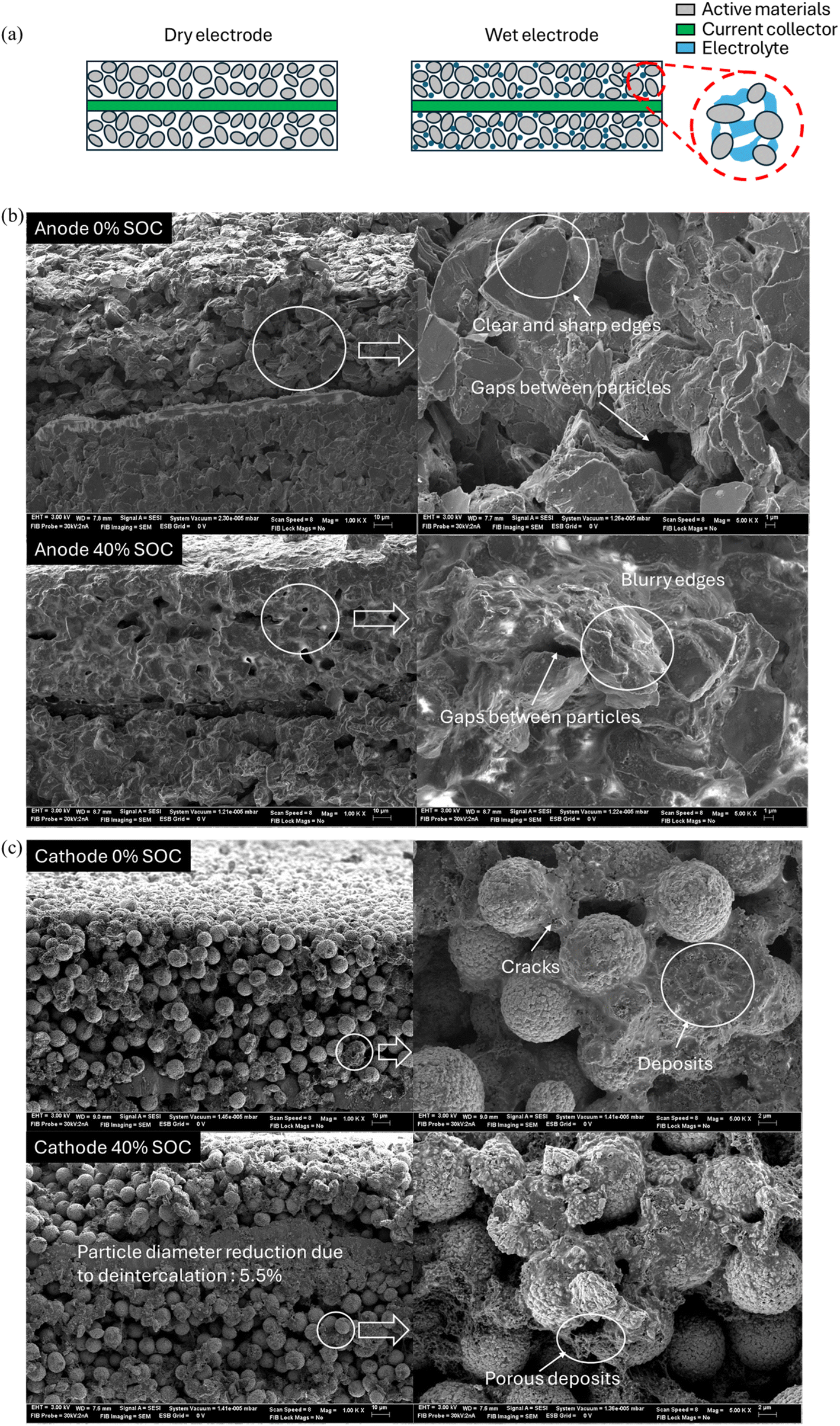 | ||
| Fig. 3 (a) Three-layer electrode structure with or without electrolyte. Active materials are treated as granular particles. Specifically, under wet conditions, the electrolyte was retained between the particles, forming liquid–air bridges to facilitate ionic conduction and mechanical interactions. Scanning electron microscopy (SEM) of the dry (b) anode and (c) cathode at 0% SOC and 40% SOC. The images present the cross sections of electrodes before the mechanical tests. The anode materials consist of particles with a rectangular shape and exhibit significant volume variation. In contrast, the cathode materials are composed of round-shaped particles. The diameters of the cathode particles were determined by measuring the pixel size of ten randomly selected particles and comparing them to a reference scale. | ||
![[small sigma, Greek, circumflex]](https://www.rsc.org/images/entities/char_e111.gif)
![[small sigma, Greek, circumflex]](https://www.rsc.org/images/entities/i_char_e111.gif) and normalized strain
and normalized strain ![[small epsilon, Greek, circumflex]](https://www.rsc.org/images/entities/i_char_e107.gif) , respectively.
, respectively.Under baseline conditions, the normalized stress–strain curve exhibits a nonlinear initial stage, where the stiffness increases due to the compaction of porosity (Fig. 4(a)). This is followed by a short plateau, representing the point where porosity is fully compacted,24 and subsequent material failure (Pf). The electrode materials containing binder exhibit plastic behavior from the very beginning of the test (Fig. S7†), primarily due to the plastic response of the granular coating components.25 As a result, we do not distinguish between elastic and plastic regions in our analysis. Instead, the effective modulus  is calculated as the maximum slope of the normalized stress–strain curve to characterize the mechanical response of the electrode. A smoothing constant Δ = 0.2 is applied to reduce noise from small variations in Δ
![[small epsilon, Greek, circumflex]](https://www.rsc.org/images/entities/char_e107.gif) and Δ will be extracted based on the Δ. Failure strain f and stress f were determined based on this curve. Post-failure analysis reveals significant fragmentation along the surface and edges of the dry anode, correlating with a sharp force drop.
and Δ will be extracted based on the Δ. Failure strain f and stress f were determined based on this curve. Post-failure analysis reveals significant fragmentation along the surface and edges of the dry anode, correlating with a sharp force drop.
 | ||
| Fig. 4 Representative compression behavior and failure morphology of electrodes under dry and wet conditions at 0% SOC: (a) anode and (b) cathode at a quasi-static loading rate. Two stages on the wet electrode were identified before and after transition point Pt. The effective modulus is calculated for the two stages separately. Failure point Pf only exists on anode materials. (c) The electrolyte influences the mechanical behavior of electrodes, exhibiting either a lock-up or lubrication effect depending on the space between particles. (d) Cross-section SEM of the wet anode and cathode after failure. Since the electrolyte may cause poor SEM resolution, the samples were exposed to air until they fully dried before SEM testing. The anode particles become more compact, showing reduced gaps between them and indicating potential particle densification. In contrast, the cathode particles exhibit significant fragmentation, with noticeable cracks and breakage in their structure. | ||
In contrast, the wet anode exhibits distinct mechanical behavior, characterized by an additional linear stage following the initial nonlinear compaction. This is accompanied by a sudden decrease in effective modulus and lower failure stress. The effective moduli for the nonlinear and linear stages (Ê1 and Ê2) were calculated separately. The maximum force for the wet anode is approximately 5% lower than that of the dry anode, indicating reduced mechanical strength due to electrolyte exposure.
For the cathode, quasi-static compression results for the dry sample at 0% SOC display a nonlinear stress–strain curve with no apparent failure behavior (Fig. 4(b)), though slight edge cracking is observed. The wet and dry cathodes exhibit similar behavior up to the transition point. Beyond this point, the effective modulus of the dry cathode continues to increase, while the wet cathode either remains constant or slightly decreases. Similar to the anode, two effective moduli were identified for the cathode corresponding to distinct stages, but no failure point was observed.
The influence of the electrolyte on electrode behavior can be attributed to two primary factors: (1) changes in material properties and (2) structural effects. Electrolyte immersion causes binder swelling, which reduces adhesion between the binder and active materials, leading to delamination. For example, the Young's modulus of a common binder (e.g., PVDF) in the electrolyte is reported to be approximately five times lower than that in its dry state.26 Additionally, active materials behave intrinsically similar to granular systems,27 where the liquid electrolyte either creates cohesive “locking” effects or lubricates particle motion, altering the mechanical response.28 The initial structure of the electrode includes a mixture of electrolyte and air between graphite particles, forming liquid bridges (Fig. 4(c)). These bridges generate cohesive forces that hinder particle motion, contributing to the initial stiffness observed in wet anodes. Despite sufficient electrolyte soaking, air gaps could exist between graphite particles, likely due to the limited absorption capacity of the electrode materials. During compression, a transition point is observed where air gaps are expelled. Beyond this point, the lubrication effect of the electrolyte becomes dominant,29 as the displaced electrolyte fills the remaining gaps between compacted particles. This transition leads to a reduction in modulus and failure stress. The expelled electrolyte was observed flowing onto the testing plates during compression, with the active material from the top surface adhering to the upper plate, exposing the underlying copper current collector. SEM analyses were conducted after the compression tests of wet conditions. Both the anode and cathode materials exhibited a more compacted particle arrangement, indicating reduced space for electrolyte storage at the end of the test.
f increases as SOC rises from 0% to 40%. Notably, a similar pattern is observed under wet conditions (Fig. 5(b)), where the SOC dependency becomes more pronounced, particularly in the linear elastic stage before failure. In this stage, the stress-strengthening phenomenon is evident at 20% and 40% SOC. Furthermore, tensile tests reveal a positive correlation between mechanical response and SOC for the anode (Fig. 6(a)). In contrast, cathode materials exhibit negligible SOC dependency under the same conditions (Fig. 6(b)). This result may be attributed to the fact that the current collector contributes the most to the cathode's tensile strength. Since the cathode thickness remains nearly unchanged, its tensile mechanical behavior tends to remain unaffected.
 | ||
| Fig. 5 Representative stress–strain curves of compression tests for (a) dry anode, (b) dry cathode, (c) wet anode, and (d) wet cathode materials with SOC equal to 0%, 20%, and 40% SOC. Failure morphology of 0% SOC and 40% SOC does not demonstrate a significant difference. (e) Multiple factors that affect the electrochemical–mechanical properties of the electrode during charging. | ||
 | ||
| Fig. 6 Average stress–strain curves of tensile tests for (a) the dry anode and (b) dry cathode with 0% SOC and 40% SOC. The effect of SOC is notably more pronounced on the anode side compared to the cathode. The failure morphology between 0% SOC and 40% SOC does not exhibit significant differences. | ||
The electrochemical–mechanical properties of electrodes during the charging process are reported to be primarily influenced by several factors (Fig. 5(e)):9 (1) particle expansion; (2) particle properties variation; and (3) binder properties variation. During charging, lithium ions intercalate into the anode (e.g., graphite), causing an expansion of the active material. Graphite experiences a lattice volume expansion of up to 13.2% during lithium intercalation.30 Macroscopic thickness measurements indicate a 1.9% average increase in anode thickness as SOC rises from 0% to 40%, contributing to an increase in the effective modulus of the sample. In contrast, although the cathode material is reported to undergo a lattice volume shrinkage of approximately 5% during charging,31 its macroscopic thickness does not exhibit significant variation as the state of charge (SOC) increases to 40%. Additionally, phase transitions occur within the anode during charging, governed by the stoichiometric ratio of lithium atoms (x) in the graphite structure. At x = 0, the battery is fully discharged to 0% SOC. During the charging, x increases until x = 1, where the anode achieves full lithiation. Qi et al.32 reported that as x increases, the polycrystalline Young's modulus of LixC6 increases from 32.47 GPa to 108.67 GPa due to phase change. Consequently, at 40% SOC, coexisting phases of partially lithiated graphite enhance the effective modulus. Additionally, lithiation-induced stress improves binder strength by promoting more cohesive contact between the binder and graphite particles.33 Notably, the influence of SOC on the tensile tests of the anode is more significant than its effect on compression tests. This may be attributed to the fact that the cohesive binder plays a more crucial role in tensile tests than in compression, becoming more brittle at higher SOC.
Conversely, dry cathode materials exhibit a negative correlation between SOC and mechanical properties, both in compression (Fig. 5(c)) and tensile tests (Fig. 6(b)). A similar trend is observed in wet cathode materials, where increasing SOC results in a softer material with lower stress resistance.
Unlike the anode, cathode materials show no significant thickness variation during charging. From an electrochemical perspective, delithiation induces phase transitions on the cathode surface, described as LiMO2 → LixMO2 + (1 − x)Li+ + (1 − x)e−,34 where x denotes the occupancy of lithium inside the lattice structure, varying from 1 to 0 as SOC increases from 0% to 100%. Microscopically, nano-indentation tests reveal a reduction in Young's modulus with increasing SOC, attributed to intergranular cracking caused by lithium delithiation.35 This crack formation further decreases the effective modulus of the cathode material at higher SOCs.
t, transition strain t, failure stress f, and failure strain f. These parameters were normalized using a baseline reference: the failure strain and stress of a 0% SOC dry anode under quasi-static loading. As discussed in Sections 3.1.1 and 3.1.2, electrode mechanical properties are influenced by a combined electrochemical and electrolyte effect. We hypothesize that this combined influence arises from two distinct mechanisms.For the anode, the first-stage effective modulus Êwet1,an of the wet anode is slightly larger than that of the dry anode Êdryan under the same SOC conditions (Fig. 7(a)). This difference can be attributed to the cohesive forces generated by electrolyte-air bridges between particles. However, in the second stage, the effective modulus of the wet anode Êwet2,an is significantly smaller due to the lubricating effects of the electrolyte. Although studies specifically isolating electrolyte effects on battery components are limited, Dixon et al.19 demonstrated that electrolyte presence induces softer mechanical behavior in cells during ball indentation tests. Regarding SOC dependency, Êwet1,an initially increases at SOC < 20% and then decreases for 20% < SOC < 40%, following a trend similar to that observed in the dry anode, as previously reported by Wang et al.36 The transition stress t,an and strain t,an of the wet anode, however, show minimal SOC variation (Fig. 7(c)), suggesting a weak SOC dependency on the electrolyte-induced transition point. Failure stress for both wet wetf,an and dry dryf,an anodes shows proportional increases with SOC. However, the ratio  rises from 0.78 at 0% SOC to 0.97 at 40% SOC, indicating that the electrolyte's influence on maximum force decreases at higher SOC levels (Fig. 7(d)). A similar trend is observed for failure strain wetf,an and dryf,an with smaller differences identified at higher SOC levels.
 | ||
| Fig. 7 Effective modulus Ê varying with SOC for both (a) the anode and (b) cathode. (c) Transition stress t and strain t for the wet cathode and anode. (d) Failure stress and failure strain for dry and wet electrodes vary with SOC. Failure stress of the wet electrode shows a larger variation with SOC. No failure behavior on the cathode side. | ||
On the cathode side, the effective modulus of the dry cathode Êdryca is 1.10, 1.76, and 1.35 times greater than the wet cathode's initial-stage modulus Êwet1,ca at 0%, 20%, and 40% SOC, respectively (Fig. 7(b)). Similarly, Êdryca is 1.39, 1.68, and 1.74 times greater than the second-stage modulus Êwet2,ca for the corresponding SOC levels, confirming a consistent softening effect of the electrolyte. Interestingly, as SOC increases, the effective modulus of the wet cathode Êwet1,ca decreases until SOC reaches 20% and then increases, highlighting the dominance of liquid-bridge lock-up effects beyond 20% SOC. Stallard et al.35 reported that during delithiation, cathode volume remains approximately constant until a certain stage (e.g., x < 0.4 for NCM) before contracting. SEM tests also indicated a 5.5% particle diameter contraction on the cathode at 40% SOC, enlarging space between particles (Fig. 3(c)). This contraction at higher SOC enhances liquid-bridge formation, inducing additional forces that dominate the mechanical behavior in the first stage. In the second stage, the cathode becomes fully compacted, reducing the electrolyte influence and leading to a decline in effective modulus, similar to trends observed in the polycrystalline Young's modulus of cathode materials. The transition stress t,ca and strain t,ca of the wet cathode are lower at elevated SOC levels, i.e., 20% and 40% SOC (Fig. 7(c)), indicating that smaller forces and displacements are required to reach the transition point.
To sum up, when analyzing the coupled effects of electrolyte and SOC under small strain rates (i.e., ![[small epsi, Greek, dot above]](https://www.rsc.org/images/entities/i_char_e0a1.gif) = 0.01 s−1), the mechanical behavior of electrode materials is governed by the competition between two mechanisms: (1) electrolyte-induced cohesion or lubrication effects and (2) electrochemically driven structural changes. These findings provide critical insights into the mechanical properties of electrodes and their dependency on SOC and electrolyte presence, offering valuable guidance for the design and optimization of battery materials under realistic operating conditions.
= 0.01 s−1), the mechanical behavior of electrode materials is governed by the competition between two mechanisms: (1) electrolyte-induced cohesion or lubrication effects and (2) electrochemically driven structural changes. These findings provide critical insights into the mechanical properties of electrodes and their dependency on SOC and electrolyte presence, offering valuable guidance for the design and optimization of battery materials under realistic operating conditions.
3.2 Strain-rate dependent compressive mechanical behavior on wet electrodes
The strain-rate dependence of compressive mechanical behavior was investigated at 0.01 s−1, 0.1 s−1, and 1 s−1 strain rates at 0%, 20%, and 40% SOC separately. For the anode electrode, at larger strain rates, i.e., 0.1 s−1 and 1 s−1, the stress–strain curves maintain a similar shape to those observed under quasi-static loading conditions, i.e., 0.01 s−1 (Fig. 8(a)). In the initial stage, stress increases at higher strain rates due to the cohesive forces induced by liquid bridges. However, in the second stage, stress decreases with increasing strain rates, highlighting the lubricating effect of the electrolyte. Additionally, the anode becomes more prone to fracture under higher compressive strain rates, as evidenced by lower failure stress and strain values. This strain-rate dependency emphasizes the competing mechanisms of liquid-bridge cohesion and electrolyte lubrication under dynamic loading conditions. Similar mechanical responses are observed at 20% SOC (Fig. 8(c)) and 40% SOC (Fig. 8(e)), indicating a uniform strain rate effect on the electrode with higher strain rates. Besides, the anode with higher SOC demonstrates a more significant transition point. In parallel, cathode materials exhibit a pronounced stress plateau stage following the initial stage (Fig. 8(b)). Failure morphology at 0.01 s−1 shows a more “moist” appearance compared to strain rates of 0.1 s−1. Since equal amounts of electrolyte were introduced into the samples, this suggests that a greater volume of electrolyte is expelled at higher strain rates. The observed stress plateau stage likely results from the increased outward flow of electrolyte, acting as a transition phase between the electrolyte-submerged initial stage and the fully compacted phase. Once the electrolyte is fully expelled, the material transitions into a stress increase region, where the cathode becomes harder due to compaction. At higher SOC, specifically at 20% and 40%, distinct regions of stress plateau and stress increase become evident. Notably, the transition between the initial stage and the stress plateau stage becomes increasingly pronounced as the SOC rises from 20% (Fig. 8(d)) to 40% (Fig. 8(f)). This trend aligns with observations made on the anode side. Furthermore, under conditions of elevated strain rates, no significant mechanical failures are detected. For clarity in discussing the strain-rate effect on the cathode, we define Ê1,ca as the effective modulus of the initial stage and Ê2,ca as that of the stress increase stage, consistent with the concepts described in Section 3.1.1.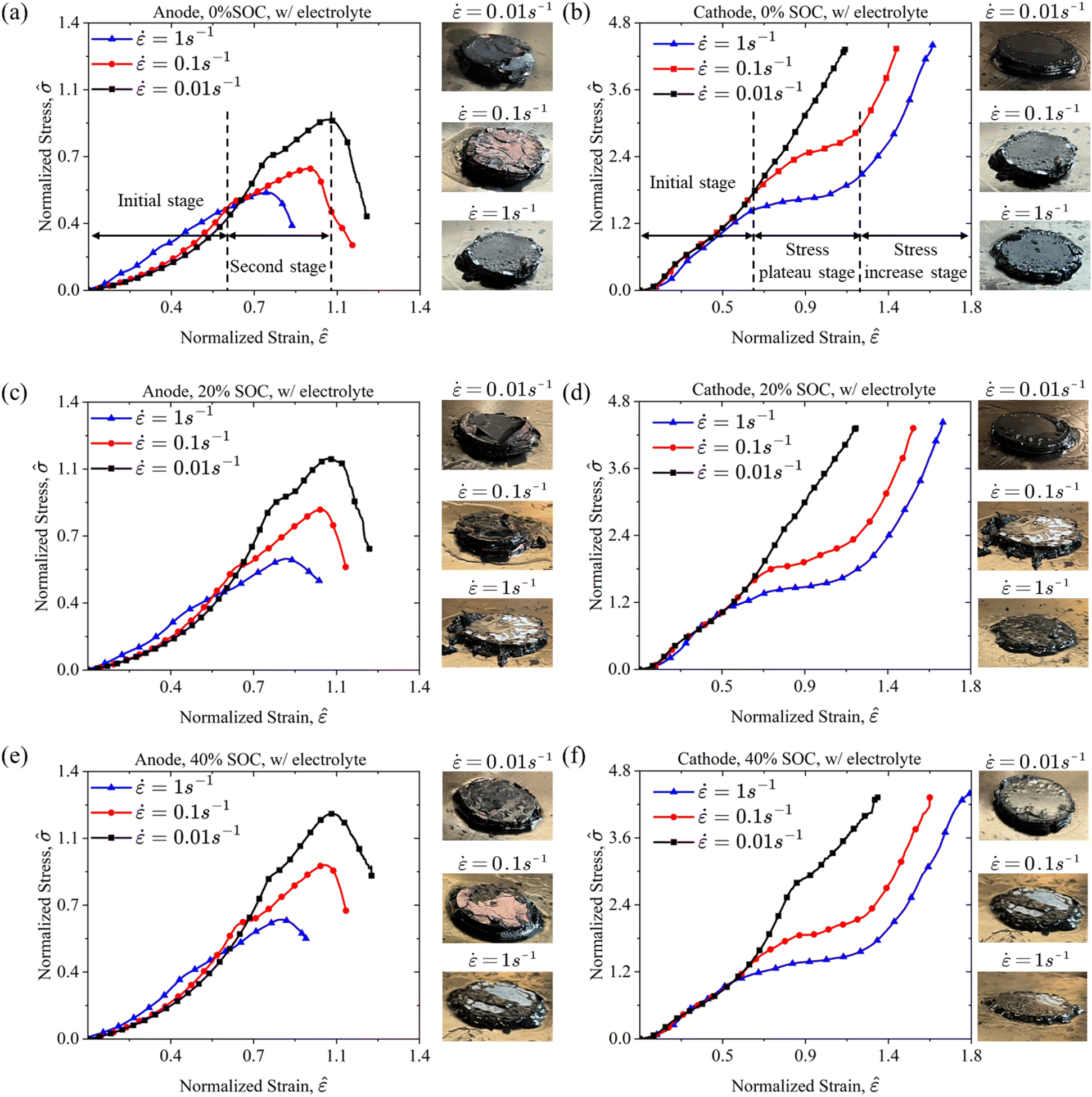 | ||
| Fig. 8 Wet electrode compression results at various strain rates (i.e., 0.01 s−1, 0.1 s−1, and 1 s−1) for (a) and (b) 0% SOC, (c) and (d) 20% SOC, (e) and (f) 40% SOC wet anode and cathode. Particularly, for the anode, the mechanical response of the electrode is characterized by two distinct stages: the initial stage and the second stage, which are consistently observed across varying strain rates. In contrast, the cathode exhibits a prominent stress plateau stage followed by a stress increase stage, particularly noticeable at strain rates = 0.1 s−1 and = 1 s−1. | ||
The effective moduli Ê1 and Ê2, failure strain f, and failure stress f of the anode, along with the transition strain t and transition stress t, were systematically analyzed across a range of SOCs and strain rates under wet conditions. This analysis provides a comprehensive understanding of the coupling effects among SOC, electrolyte behavior, and strain rates, contributing to a more detailed characterization of the anode's mechanical performance. For anode materials, the effective modulus steadily increases as the SOC rises under 0.01 s−1, 0.1 s−1, and 1 s−1 (Fig. 9(a)). At each SOC, a decreasing trend of modulus is observed as the strain rate increases in both the first and second stages, which is consistent with force response of whole cell level tests in ref. 18. Notably, the nonlinear behavior observed during the initial stage transitions toward a more linear response at higher strain rates. As a result, although the effective modulus Ê1,an decreases with increasing strain rates, the stress observed during the initial stage is higher (Fig. 8(a)). This phenomenon arises because the effective modulus is determined as the maximum slope of the stress–strain curve. Furthermore, a reduction effect of strain-rate on both Ê1,an and Ê2,an can be identified as SOC increases. When = 0.01 s−1, the effective modulus Ê1,an exhibits a 27% increase as the SOC rises from 0% to 40%. However, this increase diminishes to only 15% at = 1 s−1. Additionally, the anode materials exhibit lower failure strain and stress at elevated strain rate (Fig. 9(b)). Wang et al.37 reported a decrease in maximum force at larger strain rates during ball indentation tests on cells, suggesting a correlated mechanical response between individual components and the complete cell structure. The softening effect of strain rate also exists on the cathode side (Fig. 9(c)). The Ê1,ca0%,0.01 is 1.84 times larger than Ê1,ca0%,1. In contrast to = 0.01 s−1, Ê1,ca at = 0.1 s−1 and 1 s−1 decreases with increasing SOC when SOC exceeds 20%. This behavior is likely attributed to the dominance of strain-rate-induced softening effects during the initial stage. Under higher strain rates (i.e., = 0.1 s−1 and 1 s−1), the competition between the strain-rate and electrochemical effect leads to a decrease of Ê1,ca at higher SOC. It is interesting that a positive proportional relationship is observed for Ê2,ca under 0%, 20% and 40% SOC. This strain-rate hardening effect has been reported on dry electrode tests,38 implying that the electrolyte has been fully extracted during the restrengthening stage. Therefore, a slightly increase in Ê2,ca for 20% and 40% SOC cathodes can be observed at = 0.1 s−1 and 1 s−1 due to the domination of the strain rate effect. Furthermore, the transition point is defined as the conclusion of the initial stage under high strain rate conditions. Generally, both the transition stress t,ca and transition strain t,ca decrease with increasing strain rates, reflecting the influence of strain rate effects (Fig. 9(d)). Notably, SOC-related properties exhibit minimal variation at higher strain rates, aligning with prior findings that strain rate effects take precedence over electrochemical influences. Therefore, when coupling the SOC, electrolyte, and strain rate effects, electrolyte effect and strain rate will dominate the mechanical behaviors (e.g., Ê, t, and f).
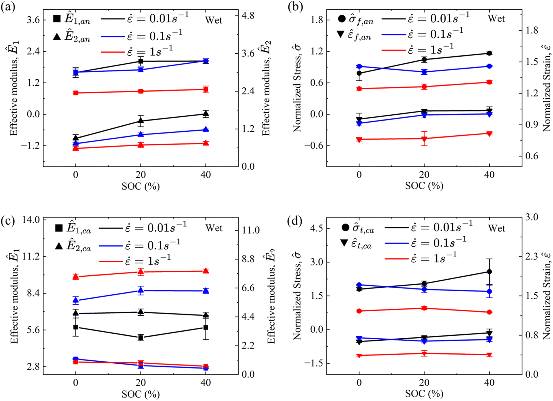 | ||
| Fig. 9 (a) Strain rate effect on the effective modulus of the anode varying with SOC. (b) Failure stress t and strain t at various strain rates (i.e., 0.01 s−1, 0.1 s−1, and 1 s−1) and SOC (i.e., 0%, 20%, and 40% SOC). (c) Strain rate effect on the effective modulus of the cathode varying with SOC. (d) Transition stress t and strain t of the cathode changing with strain rate and SOC. | ||
3.3 Strain-rate dependent mechanical behavior of wet and dry separators
The SOC of the battery does not exhibit a significant influence on separator mechanical behavior.11 Therefore, this study focuses on the coupling effects of the electrolyte and strain rate. Compression and tensile tests were conducted on wet and dry polymer separators under various strain rates.In compression tests, both wet and dry separators exhibit higher stress with increasing strain rates (Fig. 10(a)), consistent with findings reported by Cannarella et al.23 The stress–strain curves of dry separators initially show elastic mechanical behavior, during which the microstructure of the separator is compacted. As compression progresses, the material yields and transitions to nonlinear constitutive behavior. Notably, no failure behavior was observed at strain rates of 0.001 s−1, 0.1 s−1, and 1 s−1. Post-compression macroscopic observations revealed significant out-of-plane deformation, indicative of severe structural compaction (Fig. 10(d)). Li et al.39 attributed such behavior to compressive loading causing a denser microstructure and reduced porosity. Wet separators, compared to their dry counterparts, demonstrate higher stress due to reduced porosity, which restricts electrolyte movement. Unlike dry separators, the compressive response of wet separators transitions from nonlinear behavior at a low strain rate of 0.001 s−1 to linear behavior at higher strain rates, e.g., 0.1 s−1 and 1 s−1. Additionally, wet separators exhibit a more pronounced strain-rate hardening effect, with significantly greater stress increases observed at higher strain rates.
 | ||
| Fig. 10 (a) Compressive stress–stain curves of dry and wet separators at various strain rates (i.e., 0.001 s−1, 0.1 s−1, and 1 s−1). Significant difference in wet and dry separators at higher strain rates. Tensile stress–strain curves of the separator at various strain rates (i.e., 0.001 s−1, 0.05 s−1, and 0.1 s−1) in (b) the mechanical direction (MD) and (c) transverse direction (TD). The sample morphology after (d) compression tests and (e) tensile tests under various strain rates. Compression tests conducted at higher strain rates result in more compacted samples. In tensile tests, the transverse direction (TD) generally exhibits a larger failure strain, accompanied by significant lateral deformation, highlighting the anisotropic mechanical response of the materials. | ||
Generally, polymer separators exhibit anisotropic mechanical behavior in tensile tests, which was investigated along the machine direction (MD) and transverse direction (TD).23 Separators show higher failure stress in the MD compared to the TD, while the TD demonstrates greater failure strain, reflecting differences in microstructural characteristics. As the strain rate increases, the effective modulus of separators rises consistently across both the MD and TD, as well as under wet and dry conditions (Fig. 10(b)). During tensile tests, significant axial elongation and lateral shrinkage were observed (Fig. 10(e)). Electrolyte immersion has little effect on the MD, but in the TD, wet separators become noticeably softer compared to dry separators (Fig. 10(c)). This trend aligns with observations by Sheidaei et al.40 The softening effect in the TD is probably caused by the impact of electrolyte immersion. Organic solvent immersion, such as with dimethyl carbonate (DMC), has been reported to affect the separator's mechanical properties differently depending on material composition.22 For example, immersion of DMC in polyethylene (PE) increases tensile stress by inducing internal tension, whereas polypropylene (PP) materials experience a softening effect due to microstructural damage caused by immersion. Consequently, the electrolyte influence on separator behavior is orientation-dependent and varies with material composition.
4 Conclusions
This work provides a detailed and comprehensive investigation into the coupled effects of SOC, electrolyte, and strain rate on battery components, including the anode, cathode, and separator, using uniaxial compression and tensile tests. Post-mortem analyses and SEM were employed to characterize the structural and material changes underlying the observed mechanical behaviors.The key findings reveal the complex interplay between SOC and electrolyte effects. For the anode, the mechanical properties (i.e., Ê1, Ê2, and f) increase with SOC rising from 0% to 40% under dry conditions. The presence of the electrolyte modifies the constitutive behavior of anodes, introducing distinct structural effects: a “lock-up” effect during the initial stage and a “lubrication” effect during subsequent stages. These electrolyte effects significantly reduce both the effective modulus and failure stress compared to dry conditions, highlighting a transition point in the anode mechanical behavior. Lithium-ion intercalation predominantly governs mechanical changes at lower SOC levels (0–40%), where the electrolyte locking and lubricating effects are most pronounced.
For the cathode, SOC has a negative influence on the mechanical properties under dry conditions, with a decrease in the effective modulus as SOC rises. No failure behavior was identified for either dry or wet cathodes under the tested conditions. Electrolyte effects in the cathode exhibit a two-stage behavior similar to the anode, with E1,ca decreasing at lower SOCs and increasing at higher SOCs due to the competition between SOC-induced structural changes and electrolyte effects.
The strain rate effects on wet electrodes and separators were also thoroughly analyzed. A softening effect was observed across various SOC levels, with significant changes in the constitutive behavior of the cathode under higher strain rates. Specifically, a stress plateau stage was identified, followed by a stress increase stage as the electrolyte was expelled from the microstructure. For separators, the coupling effects of the electrolyte and strain rate were shown to dominate mechanical behavior, particularly in tensile tests, where anisotropic responses were evident along the machine and transverse directions.
By isolating single-factor mechanisms and examining their interactions, this study highlights that when SOC, electrolyte, and strain rate are coupled, the combined effects of the electrolyte and strain rate dominate the mechanical behavior. These findings provide critical insights into the mechanical performance of battery components under realistic operating conditions, offering valuable guidance for the design and optimization of next-generation lithium-ion batteries with enhanced safety and reliability.
Nomenclature
| Ê | Normalized Young's modulus (MPa) |
| V | Volume (m3) |
| Normalized nominal stress (1) |
| Normalized nominal strain (1) |
| Strain rate (s−1) |
Subscripts
| e | Electrolyte |
| an | Anode |
| ca | Cathode |
| sample | Sample scale |
| cell | Cell scale |
| t | Transition point |
| f | Failure point |
| 1 | Stage I |
| 2 | Stage II |
Superscripts
| wet | Wet conditions |
| dry | Dry conditions |
| 0% | SOC = 0% |
| 20% | SOC = 20% |
| 40% | SOC = 40% |
| 0.01 | = 0.01 s−1 |
| 1 | = 1 s−1 |
Data availability
All data supporting the results reported in this study are fully presented within the manuscript.Author contributions
Shuguo Sun: methodology, data analysis, and writing – original draft; Bo Rui: experiment, data analysis and methodology; Xijun Tan: experiment, data analysis and methodology; Saurabh Bahuguna: conceptualization and writing – review; Jun Zhou: conceptualization and writing – review; Jun Xu: conceptualization, methodology, supervision, and writing – review & editing.Conflicts of interest
The authors declare that they have no known competing financial interests or personal relationships that could have appeared to influence the work reported in this paper.Acknowledgements
JX was supported by the research project from General Motors.References
- L. Peiseler, V. Schenker, K. Schatzmann, S. Pfister, V. Wood and T. Schmidt, Carbon footprint distributions of lithium-ion batteries and their materials, Nat. Commun., 2024, 15, 10301, DOI:10.1038/s41467-024-54634-y.
- Y. Jia, X. Gao, L. Ma and J. Xu, Comprehensive Battery Safety Risk Evaluation: Aged Cells versus Fresh Cells Upon Mechanical Abusive Loadings, Adv. Energy Mater., 2023, 13, 2300368, DOI:10.1002/aenm.202300368.
- X. Gao, C. Chak, Q. Hao, D. Zeng and J. Xu, Thermal Safety Of Lithium-Ion Batteries: Mechanism, Modeling, And Characterizations, Annu. Rev. Heat Transfer, 2023, 26, 69–129, DOI:10.1615/AnnualRevHeatTransfer.2023048695.
- W. Li, X. Wu, K. Wang, M. Ling, Z. Lin, M. Wang, H. Sun, K. Wu and C. Liang, Insights into the swelling force in commercial LiFePO4 prismatic cell, J. Power Sources, 2024, 622, 235330, DOI:10.1016/j.jpowsour.2024.235330.
- D. Song, X. Chen, H. Chen, T. Wang, Q. Wang and Q. Yuan, Investigation of the mechanical response and modeling of prismatic lithium-ion batteries upon abusive loading, J. Energy Storage, 2024, 104, 114489, DOI:10.1016/j.est.2024.114489.
- A. Sonwane, C. Yuan and J. Xu, Coupling Effect of State-of-Charge and Strain Rate on the Mechanical Behavior of Electrodes of 21700 Lithium-Ion Battery, J. Electrochem. Energy Convers. Storage, 2021, 18, 020905, DOI:10.1115/1.4049042.
- J. Xu, Y. Jia, B. Liu, H. Zhao, H. Yu, J. Li and S. Yin, Coupling Effect of State-of-Health and State-of-Charge on the Mechanical Integrity of Lithium-Ion Batteries, Exp. Mech., 2018, 58, 633–643, DOI:10.1007/s11340-018-0380-9.
- X. Huang, H. Yang, W. Liang, M. Raju, M. Terrones, V. H. Crespi, A. C. T. Van Duin and S. Zhang, Lithiation induced corrosive fracture in defective carbon nanotubes, Appl. Phys. Lett., 2013, 103, 153901, DOI:10.1063/1.4824418.
- L. Wang, Y. Jia and J. Xu, Mechanistic understanding of the electrochemo-dependent mechanical behaviors of battery anodes, J. Power Sources, 2021, 510, 230428, DOI:10.1016/j.jpowsour.2021.230428.
- Z. Pan, T. Sedlatschek and Y. Xia, Effect of State-of-Charge and Air Exposure on Tensile Mechanical Properties of Lithium-Ion Battery Electrodes, J. Electrochem. Soc., 2020, 167, 090517, DOI:10.1149/1945-7111/ab8804.
- J. Xu, B. Liu and D. Hu, State of Charge Dependent Mechanical Integrity Behavior of 18650 Lithium-ion Batteries, Sci. Rep., 2016, 6, 21829, DOI:10.1038/srep21829.
- Y. Jia, S. Yin, B. Liu, H. Zhao, H. Yu, J. Li and J. Xu, Unlocking the coupling mechanical-electrochemical behavior of lithium-ion battery upon dynamic mechanical loading, Energy, 2019, 166, 951–960, DOI:10.1016/j.energy.2018.10.142.
- X. Duan, J. Li, Y. Jia, X. Gao, L. Wang and J. Xu, Understanding of Stress-Driven Internal Short Circuit Mechanisms in Lithium-Ion Batteries with High SOCs, Adv. Sci., 2023, 10, 2302496, DOI:10.1002/advs.202302496.
- L. Yiding, W. Wenwei, L. Cheng, Y. Xiaoguang and Z. Fenghao, Multi-physics safety model based on structure damage for lithium-ion battery under mechanical abuse, J. Clean. Prod., 2020, 277, 124094, DOI:10.1016/j.jclepro.2020.124094.
- J. Chen, B. Li, J. Li, Y. Gao, Z. Hao and L. Wang, Exploring the electrochemical and mechanical properties of lithium-ion batteries in salt spray environments, eTransportation, 2024, 20, 100324, DOI:10.1016/j.etran.2024.100324.
- W. Li, Y. Xia, J. Zhu and H. Luo, State-of-Charge Dependence of Mechanical Response of Lithium-Ion Batteries: A Result of Internal Stress, J. Electrochem. Soc., 2018, 165, A1537–A1546, DOI:10.1149/2.0051809jes.
- J. Zhu, T. Wierzbicki and W. Li, A review of safety-focused mechanical modeling of commercial lithium-ion batteries, J. Power Sources, 2018, 378, 153–168, DOI:10.1016/J.JPOWSOUR.2017.12.034.
- T. Kisters, M. Keshavarzi, J. Kuder and E. Sahraei, Effects of electrolyte, thickness, and casing stiffness on the dynamic response of lithium-ion battery cells, Energy Rep., 2021, 7, 6451–6461, DOI:10.1016/j.egyr.2021.09.107.
- B. Dixon, A. Mason and E. Sahraei, Effects of electrolyte, loading rate and location of indentation on mechanical integrity of li-ion pouch cells, J. Power Sources, 2018, 396, 412–420, DOI:10.1016/j.jpowsour.2018.06.042.
- P. Gupta, M. Streb, A. Siddiqui, M. Klett, G. Lindbergh and P. Gudmundson, Layer-Resolved Mechanical Degradation of a Ni-Rich Positive Electrode, Batteries, 2023, 9, 575, DOI:10.3390/batteries9120575.
- G. Y. Gor, J. Cannarella, C. Z. Leng, A. Vishnyakov and C. B. Arnold, Swelling and softening of lithium-ion battery separators in electrolyte solvents, J. Power Sources, 2015, 294, 167–172, DOI:10.1016/j.jpowsour.2015.06.028.
- W. Zhao, Z. Guo, Z. Ma, S. Wang, S. Yang, J. Liu, H. Zhao and L. Ren, Coupled Effect of Low Temperature and Electrolyte Immersion on the Tensile Properties of Separators in Lithium-Ion Batteries, ACS Appl. Mater. Interfaces, 2023, 15, 41783–41792, DOI:10.1021/acsami.3c05450.
- J. Cannarella, X. Liu, C. Z. Leng, P. D. Sinko, G. Y. Gor and C. B. Arnold, Mechanical Properties of a Battery Separator under Compression and Tension, J. Electrochem. Soc., 2014, 161, F3117–F3122, DOI:10.1149/2.0191411jes.
- Z. Li, J. Chen, F. Lan and Y. Li, Constitutive Behavior and Mechanical Failure of Internal Configuration in Prismatic Lithium-Ion Batteries under Mechanical Loading, Energies, 2021, 14, 1219, DOI:10.3390/en14051219.
- J. Zhu, W. Li, T. Wierzbicki, Y. Xia and J. Harding, Deformation and failure of lithium-ion batteries treated as a discrete layered structure, Int. J. Plast., 2019, 121, 293–311, DOI:10.1016/j.ijplas.2019.06.011.
- J. M. Foster, X. Huang, M. Jiang, S. J. Chapman, B. Protas and G. Richardson, Causes of binder damage in porous battery electrodes and strategies to prevent it, J. Power Sources, 2017, 350, 140–151, DOI:10.1016/j.jpowsour.2017.03.035.
- J. Zhu, W. Li, Y. Xia and E. Sahraei, Testing and Modeling the Mechanical Properties of the Granular Materials of Graphite Anode, J. Electrochem. Soc., 2018, 165, null, DOI:10.1149/2.0141807JES.
- L. Varley, M. E. Rutherford, L. Zhang and A. Pellegrino, The Mechanical Response of Wet Volcanic Sand to Impact Loading, Effects of Water Content and Initial Compaction, J Dynamic Behavior Mater., 2020, 6, 358–372, DOI:10.1007/s40870-020-00257-5.
- N. Mitarai and F. Nori, Wet granular materials, Adv. Phys., 2006, 55, 1–45, DOI:10.1080/00018730600626065.
- S. Schweidler, L. De Biasi, A. Schiele, P. Hartmann, T. Brezesinski and J. Janek, Volume Changes of Graphite Anodes Revisited: A Combined Operando X-ray Diffraction and In Situ Pressure Analysis Study, J. Phys. Chem. C, 2018, 122, 8829–8835, DOI:10.1021/acs.jpcc.8b01873.
- W. Li, H. Y. Asl, Q. Xie and A. Manthiram, Collapse of LiNi 1– x – y Co x Mn y O2 Lattice at Deep Charge Irrespective of Nickel Content in Lithium-Ion Batteries, J. Am. Chem. Soc., 2019, 141, 5097–5101, DOI:10.1021/jacs.8b13798.
- Y. Qi, H. Guo, L. G. Hector and A. Timmons, Threefold Increase in the Young's Modulus of Graphite Negative Electrode during Lithium Intercalation, J. Electrochem. Soc., 2010, 157, A558, DOI:10.1149/1.3327913.
- A. Balakrishnan, C. L. Martin, B. P. Saha and S. Joshi, Modelling of Compaction and Green Strength of Aggregated Ceramic Powders: Modelling of Compaction and Green Strength of Aggregated Ceramic Powders, J. Am. Ceram. Soc., 2011, 94, 1046–1052, DOI:10.1111/j.1551-2916.2010.04237.x.
- C. H. Lee, B. Jun, S. C. Lee and S. U. Lee, State of charge dependent ordered and disordered phases in a Li[Ni 1/3 Co 1/3 Mn 1/3 ]O 2 cathode material, Mater. Adv., 2021, 2, 3965–3970, 10.1039/D1MA00289A.
- J. C. Stallard, L. Wheatcroft, S. G. Booth, R. Boston, S. A. Corr, M. F. L. De Volder, B. J. Inkson and N. A. Fleck, Mechanical properties of cathode materials for lithium-ion batteries, Joule, 2022, 6, 984–1007, DOI:10.1016/j.joule.2022.04.001.
- L. Wang, Coupled effect of SOC and SOH on tensile behaviors of lithium-ion battery electrodes, J. Energy Storage, 2023, 68, 107782 CrossRef.
- C. Wang, R. Wang, C. Zhang and Q. Yu, Coupling effect of state of charge and loading rate on internal short circuit of lithium-ion batteries induced by mechanical abuse, Appl. Energy, 2024, 375, 124138, DOI:10.1016/j.apenergy.2024.124138.
- L. Wang, S. Yin, C. Zhang, Y. Huan and J. Xu, Mechanical characterization and modeling for anodes and cathodes in lithium-ion batteries, J. Power Sources, 2018, 392, 265–273, DOI:10.1016/j.jpowsour.2018.05.007.
- H. Li, J. Gu, Y. Pan, B. Liu and C. Zhang, On the strain rate-dependent mechanical behavior of PE separator for lithium-ion batteries, Int. J. Impact Eng., 2024, 194, 105079, DOI:10.1016/j.ijimpeng.2024.105079.
- A. Sheidaei, X. Xiao, X. Huang and J. Hitt, Mechanical behavior of a battery separator in electrolyte solutions, J. Power Sources, 2011, 196, 8728–8734, DOI:10.1016/j.jpowsour.2011.06.026.
Footnotes |
| † Electronic supplementary information (ESI) available. See DOI: https://doi.org/10.1039/d5ta02137e |
| ‡ Note that here the thickness refers to the SOC = 0 status and the thickness may vary due to the SOC effect. |
| This journal is © The Royal Society of Chemistry 2025 |