
 Open Access Article
 This Open Access Article is licensed under a Creative Commons Attribution-Non Commercial 3.0 Unported Licence
On the impact of selective donor:acceptor structural ordering in PBDB-T:ITIC organic solar cells†
Xabier Rodríguez-Martínez *a,
Sara Marinab,
Albert Harillo-Bañosc,
Mariano Campoy-Quilesc and
Jaime Martin*ab
*a,
Sara Marinab,
Albert Harillo-Bañosc,
Mariano Campoy-Quilesc and
Jaime Martin*ab
aCentro de Investigación en Tecnoloxías Navais e Industriais (CITENI), Universidade da Coruña, Ferrol, 15403, Spain. E-mail: xabier.rodriguez@udc.es; jaime.martin.perez@udc.es
bPOLYMAT, Universidad del País Vasco, Donostia-San Sebastián, 20018, Spain
cInstituto de Ciencia de Materiales de Barcelona (ICMAB-CSIC), Bellaterra, 08193, Spain
First published on 30th May 2025
Abstract
The bulk heterojunction (BHJ) is the standard configuration of the photoactive layer in single-junction organic solar cells. Therein, electron-rich (a donor polymer) and electron deficient (a small molecule acceptor) organic semiconductors are intimately blended to form a complex 3D network of crystallites and vitrified regions that altogether determine the final device performance. Studying the relationship between said performance and the structural order achieved in the photoactive materials individually is desirable to discern the underlying structure–function relationship in organic solar cells, hence isolating, with no ambiguities, the role played by the structural order achieved in the donor and acceptor domains themselves on the device performance. This work precisely tackles the archetypal PBDB-T:ITIC blend to demonstrate how the structural order of the donor and acceptor fractions in the BHJ can be selectively tailored through an adequate selection of co-solvents during the film formation process. When using chloroform as unique solvent, both components exhibit a low degree of order in the BHJ. Conversely, the use of ortho-xylene yields BHJs in which PBDB-T shows enhanced structural order. Furthermore, the addition of 1,8-diiodooctane as co-solvent is found to spark the crystallization of ITIC without effect on the degree of order of PBDB-T, resulting in downgraded photovoltaic performance. Overall, BHJs in which ITIC remains in its vitrified state are beneficial, in which case the structural order achieved by PBDB-T has little to no effect. Notwithstanding, BHJs that contain ordered materials (donor and/or acceptor) show virtually no degradation after more than 3.5 years of shelf storage. This study, thus, pinpoints to (i) the microstructure attained by the acceptor domains and (ii) the presence of crystalline domains of either type (donor and/or acceptor) as the main determinants of the maximum achievable performance and the shelf stability of organic solar cells, respectively.
Introduction
Organic photovoltaics (OPVs) is a light-to-electricity energy conversion technology that relies on organic semiconductors, namely, conjugated polymers and small molecules, as the light harvesting and current generating materials.1 As these can be made soluble (e.g., by incorporating side chains) in a variety of organic solvents, OPV devices are poised to be reliably printed in high-throughput roll-to-roll coating lines.2 Such a versatile manufacturing method adds to their intrinsic dependence on earth-abundant raw materials and their low toxicity to make OPVs a highly sustainable technology with low embodied energy and carbon footprint in its corresponding functional devices.3,4 Therein, an intimate mixture of hole transporting and electron transporting semiconducting materials (i.e., the electron donor and the electron acceptor, respectively) organized in the so-called bulk heterojunction (BHJ) is up to date the most successful approach to form high-performing photoactive layers (PALs) in single-junction organic solar cells, with the record power conversion efficiency (PCE) exceeding 20% in laboratory scale.5,6The apparent simplicity of the BHJ film formation, where the donor and acceptor materials are weighed and mixed in either a neat solvent or a formulation of co-solvents to then be deposited atop a substrate, is also its biggest puzzle. Particularly, the pre-aggregation of the donor (typically a conjugated polymer) and the acceptor (typically a conjugated small molecule) while in solution state and the development of the liquid-to-solid transition to form a nanometric PAL are paramount to setup the correct solid-state microstructure and nanomorphology, hence the performance of solution-processed organic solar cells.7,8
Within the vast experimental parameter space at reach, processing variables such as the choice of solvents and additives (i.e., co-solvents) have proven to be an effective tool to modify the BHJ microstructure since they accordingly tune the pre-aggregation behavior of the organic semiconductors while in solution.9–12 The use of different neat solvents such as chloroform (CF), chlorobenzene (CB) or o-xylene (o-xy), can per se induce distinct donor polymer or acceptor aggregation behaviors linked to their solubility,13,14 and affect the BHJ formation due to their dissimilar viscosity, vapor pressure and boiling point. When high-boiling point co-solvents such as 1,8-diiodooctane (DIO) or 1-chloronaphthalene take a small volume fraction of the ink (typically ≤3 vol%), they are usually referred to as additives. By delaying the drying of the BHJ film, they serve to selectively enhance the crystallization of the acceptor material, either the classical fullerenes15 or the so-called non-fullerene acceptors (NFAs).16–19 Furthermore, high-boiling point additives are also used to tune the size of the donor:acceptor phase domains of the BHJ.20 Nevertheless, slight maladjustments of the ink formulation, as subtle as 0.25 vol%, can result in severe device performance and stability downgrades. In these cases, the deviations from device-optimized morphology conditions have been extensively related, on the one hand, to the acceptor (over)crystallization resulting in mixed phases depletion21,22 or demixing through thermodynamic relaxation of the initial BHJ quenched composition.8,23 On the other hand, anomalies in the BHJ morphology may include the donor polymer as well. Particularly, and in view of our recently introduced microstructural model of the conjugated polymer semi-paracrystallinity,24 the influence of the donor polymer paracrystals, the evolution of their ordering and the direct correlation with the morphological characteristics and function of the organic solar cells remain elusive. This occurs since advanced morphology-function and stability prediction models for organic solar cells25,26 were so far built on the premise that archetypal donor polymer materials such as PBDB-T or PM6 are amorphous. Within a microstructural model of the BHJ in which donor polymer paracrystals coexist with (non-)crystalline acceptor domains, it is convenient to control and finely adjust the aggregation states of the donor and acceptor materials individually and on demand. This enables the study of (i) their unique effect on the resulting mixed (donor:acceptor) BHJ morphology; and (ii) the influence on the resulting device performance. Overall, this information will provide useful guidelines in the development of more complete morphology-function models for organic solar cells and improve our understanding of the influence of the donor and acceptor aggregation states on the ultimate photovoltaic figure of merit, i.e., the PCE.
This work precisely studies the structure-morphology (X-ray diffraction) and function (solar cells) relationship of the workhorse PBDB-T:ITIC blend processed from a careful selection of co-solvent formulations. These are designed to allow the individual control of the structural order of the donor and acceptor components in the BHJ, which are shown to separately remain in their disordered (vitrified) or crystalline states. This approach allows delineating the relevant effect of enhanced ordering of the individual components within the overall BHJ morphology, with direct impact on the solar cell function. On the one hand, when casting PBDB-T and its blend with ITIC from o-xy-rich formulations, the polymer shows enhanced degree of structural order; PBDB-T remains in a less ordered state when casted from other solvents, even when DIO is present in the ink. On the other hand, ITIC strongly crystallizes as soon as DIO is added to the ink (up to 1 vol%) regardless the primary solvent used, a phenomenon that is further verified by means of Raman spectroscopy. In this latter case, the device performance drops dramatically (down to 5.5%) due to the over purification and excessive growth of the donor and acceptor domains, which is also confirmed by an increased photoluminescence (PL) yield in DIO-rich scenarios. Significantly improved record PCEs are observed when the PAL is processed from either o-xy (8.7%) or CF (9.8%), i.e., in those scenarios where ITIC remains in an amorphous state regardless the degree of order achieved by the donor polymer (less- or highly-ordered states in CF and o-xy, respectively). Furthermore, in these cases the corresponding organic solar cells show competitive performance metrics when blade coated PALs as thick as 200 nm are used. Nevertheless, in terms of device shelf stability it is herein detected that BHJs containing ordered domains of either type (donor and/or acceptor) result in virtually unaffected device performances after dark and inert storage for more than 3.5 years. Overall, this work demonstrates that in PBDB-T:ITIC blends (i) the structural order of the acceptor fraction in the BHJ is the most determinant factor in regard to the maximum achievable PCE, and (ii) the presence of ordered material fractions of any type (donor and/or acceptor) improves the device shelf stability. As a result, the present investigation pinpoints to o-xy as an adequate solvent to balance performance and stability in PBDB-T:ITIC blends while potentially enabling their scalability (due to its non-halogenated nature) and PAL thickness resilience.
Results and discussion
The microstructure of neat PBDB-T and ITIC, and their corresponding 1![[thin space (1/6-em)]](https://www.rsc.org/images/entities/char_2009.gif) :1 (w:w) blend thin films, are first studied by means of grazing incidence wide-angle X-ray scattering (GIWAXS). PBDB-T:ITIC are blended in a 1:1 weight ratio as it matches the reported optimum composition in OPV devices.27,28 Thin films are spin-coated from four different (co-)solvent formulations: CF, o-xy, o-xy:DIO (99:1, v:v); and CB:DIO (99:1, v:v). The addition of 1 vol% DIO in the present blend system was reported to yield poorer device properties due to the formation of larger crystal domain sizes, and it was here selected to complement morphological and microstructural comparisons with respect to benchmark solvents (e.g., CF).29 As shown in Fig. 1 and by adhering to the abovementioned selection of (co-)solvents, the order of the PBDB-T backbones and the ITIC molecules can be individually tuned: from less-ordered and amorphous states, to highly-ordered and crystalline scenarios.
:1 (w:w) blend thin films, are first studied by means of grazing incidence wide-angle X-ray scattering (GIWAXS). PBDB-T:ITIC are blended in a 1:1 weight ratio as it matches the reported optimum composition in OPV devices.27,28 Thin films are spin-coated from four different (co-)solvent formulations: CF, o-xy, o-xy:DIO (99:1, v:v); and CB:DIO (99:1, v:v). The addition of 1 vol% DIO in the present blend system was reported to yield poorer device properties due to the formation of larger crystal domain sizes, and it was here selected to complement morphological and microstructural comparisons with respect to benchmark solvents (e.g., CF).29 As shown in Fig. 1 and by adhering to the abovementioned selection of (co-)solvents, the order of the PBDB-T backbones and the ITIC molecules can be individually tuned: from less-ordered and amorphous states, to highly-ordered and crystalline scenarios.
 | ||
| Fig. 1 2D GIWAXS diffractograms of PBDB-T (a)–(d), ITIC (e)–(h) and their 1:1, w:w blend (i)–(l) as processed from four different co-solvent formulations: CF (first column), o-xy (second column), o-xy:DIO (99:1, v:v, third column) and CB:DIO (99:1, v:v, fourth column). | ||
The diffraction patterns of pure PBDB-T spin-coated from all four different co-solvent formulations are shown in Fig. 1a–d. π-stacking features are similar in all scenarios showing up at a scattering vector, q, of 16.9 nm−1 and exhibiting an X-ray crystalline coherence length, CCL, of 1.5 nm, see Table 1. Conversely, the lamellar peak of PBDB-T at q = 3.3 nm−1 is more sensitive to processing, which affects both peak intensity and breadth. Overall, CF (Fig. 1a) and CB/DIO (Fig. 1d) lead to less-ordered film morphologies as compared to o-xy (Fig. 1b) and o-xy/DIO (Fig. 1c) counterparts, in which brighter and sharper lamellar peaks are observed. In particular, the intensity of the first lamellar order is significantly increased and even a third diffraction-order peak is observed in the out-of-plane direction when PBDB-T is processed from o-xy (Fig. 1b and the corresponding GIWAXS linecuts in Fig. S1, ESI†), thus suggesting a notorious improvement in the structural order. This is quantitatively confirmed by its larger CCL and lower paracrystallinity disorder parameter (g) in Table 1. The effect of DIO addition on the PBDB-T microstructure is systematically evaluated using either o-xy (Fig. S2, ESI†) or CB as main solvent (Fig. S3, ESI†). These results confirm that DIO has limited effect narrowing the lamellar peaks of PBDB-T and that the improved crystallinity is mainly ascribed to the use of o-xy as primary solvent. Comparatively, the effect of DIO addition on the ITIC microstructure is significantly more pronounced (vide infra). One potential explanation for the observed behavior can be argued from the solubility of PBDB-T on the different solvents, as determined by their corresponding Hansen solubility parameters (HSPs) (Table S1, ESI†). The HSPs of PBDB-T are the closest to CF in the Hansen space which, together with its low boiling point, implies that the films form quickly promoting a more disordered phase. Conversely, the distance between PBDB-T and the remaining co-solvents (o-xy, CB, DIO) in the Hansen space (i.e., Ra) is at least 60% higher and their boiling points are also notably higher (Table S1, ESI†). Arguably, these processing conditions enable the potential preaggregation of the polymer in solution and/or its enhanced crystallization during the film formation due to longer drying times.
:1 (w:w) blends with ITIC processed from four different co-solvent formulations. For ITIC, the ‘Lamellar (100)’ column refers to the most intense periodic aromatic–aliphatic packing reflection30 observed in-plane; and the ‘π–π peak’ corresponds to the most intense reflection observed in the out-of-plane direction. Errors were calculated according to the variance formula while assuming a 5% experimental error in the fitted q and FWHM values
| Material | Solvent | Lamellar (100) | π–π peak | ||||
|---|---|---|---|---|---|---|---|
| q, nm−1 (d, nm) | CCL (nm) | g (%) | q, nm−1 (d, nm) | CCL (nm) | g (%) | ||
| PBDB-T | CF | 3.6 (1.75) | 4.0 ± 0.4 | 25.0 ± 0.9 | 16.9 (0.37) | 1.5 ± 0.3 | 18.7 ± 0.7 |
| o-xy | 3.3 (1.91) | 4.9 ± 0.5 | 23.6 ± 0.8 | 16.9 (0.37) | 1.6 ± 0.3 | 18.4 ± 0.6 | |
| o-xy/DIO | 3.2 (1.95) | 5.6 ± 0.5 | 22.3 ± 0.8 | 16.8 (0.37) | 1.1 ± 0.2 | 21.8 ± 0.8 | |
| CB/DIO | 3.0 (2.06) | 3.8 ± 0.4 | 28 ± 1 | 17.1 (0.37) | 1.6 ± 0.3 | 18.2 ± 0.6 | |
| ITIC | CF | 3.4 (1.85) | 4.0 ± 0.4 | 25.6 ± 0.9 | 15.9 (0.40) | 0.6 ± 0.2 | 30 ± 1 |
| o-xy | — | — | — | — | — | — | |
| o-xy/DIO | 3.3 (1.92) | 7.7 ± 0.6 | 18.8 ± 0.7 | 16.6 (0.38) | 1.3 ± 0.3 | 20.4 ± 0.7 | |
| CB/DIO | 3.4 (1.86) | 8.8 ± 0.7 | 17.4 ± 0.6 | 16.1 (0.39) | 1.2 ± 0.2 | 21.6 ± 0.8 | |
| PBDB-T:ITIC | CF | 3.4 (1.82) | 3.7 ± 0.4 | 26.5 ± 0.9 | 17.4 (0.36) | 1.4 ± 0.3 | 19.1 ± 0.7 |
| o-xy | 3.3 (1.90) | 5.4 ± 0.5 | 22.4 ± 0.8 | 17.0 (0.37) | 1.3 ± 0.3 | 20.5 ± 0.7 | |
| o-xy/DIO | 3.1 (2.00) | 3.7 ± 0.4 | 28 ± 1 | 16.9 (0.37) | 3.2 ± 0.4 | 13.0 ± 0.5 | |
| CB/DIO | 3.3 (1.90) | 6.7 ± 0.6 | 20.2 ± 0.7 | 16.6 (0.38) | 1.2 ± 0.2 | 20.9 ± 0.7 | |
For ITIC, 2D GIWAXS diffractograms (Fig. 1e–h) indicate that after film processing from neat solvents such as CF (Fig. 1e) and o-xy (Fig. 1f and Fig. S4, ESI†), the resulting microstructure is essentially amorphous or vitrified. A few broad reflections are resolved when ITIC is processed from CF which confirm, however, that the degree of molecular order achieved therein is very low as g > 25.0% (Table 1). These reflections correspond to the periodic aromatic–aliphatic packing reflection observed in-plane, with q = 3.4 nm−1; and the π–π peak assigned at q = 15.9 nm−1 (Table 1). In the case of ITIC films casted from o-xy, those same reflections are missing. That is not the case, however, when ITIC is processed from neat CB, in which case a sharp reflection arises in the out-of-plane direction (Fig. S5, ESI†). On the other hand, in all cases studied (both in o-xy:DIO and CB:DIO cases, Fig. 1g and h) the addition of DIO in variable fractions (from 0.25 vol% up to 1 vol%) clearly promotes the strong crystallization of ITIC. NFAs such as ITIC are known to crystallize in various polymorphs, i.e., in different crystal forms, with the resulting optoelectronic properties affected by the dissimilar overlap between π-orbitals in the solid state.30 In the present case, the addition of DIO as co-solvent is found to promote the crystallization of ITIC into its low-temperature phase I polymorph, in agreement with previous observations.30 Such a polymorph develops naturally under specific processing conditions, while the remaining ITIC polymorphs (phase II and phase III) develop upon further thermal treatments only.30 Quantitatively, the addition of DIO nearly doubles the CCL of the characteristic ITIC reflections detailed in Table 1 when compared to those observed in CF-based films. Comparatively, the morphology of PBDB-T is not affected as much as that of ITIC after the addition of DIO.
A side-by-side comparison of the scattering patterns obtained in the corresponding 1:1 (w:w) blend films (Fig. 1i–l) serves, thus, to distinguish different microstructural ordering scenarios in the donor (PBDB-T) and acceptor (ITIC) components, namely:
• Poorly ordered donor and acceptor, as observed in films processed from CF as solvent (Fig. 1a, e, and i). In this case both components remain in their most disordered or glassy state. The diffraction pattern of the blend (Fig. 1i) does not show reflections attributed to ITIC, and the only reflections retrieved are those observed originally in the mostly disordered PBDB-T films (Fig. 1a).
• Highly ordered donor and poorly ordered acceptor, a scenario achieved upon processing from o-xy (Fig. 1b, f, and j). In this case, no signs of ITIC-related scattering peaks are observed (Fig. 1j) suggesting that ITIC is either in its amorphous state or that its crystallinity has significantly decreased after blending. Interestingly, the GIWAXS pattern of the blend (Fig. 1j) still preserves the improved lamellar order observed in the neat PBDB-T film (Fig. 1b).
• Highly ordered donor and acceptor, obtained upon processing from o-xy/DIO (Fig. 1c, g, and k). Here the GIWAXS diffractogram of the blend (Fig. 1k) shows multiple sharp peaks, including the lamellar peak at q = 5.1 nm−1 attributed to ITIC and the diffuse scattering of the π–π planes of ITIC (Fig. 1g). The crystallinity of the acceptor is significantly amplified and it screens the π–π stacking peak of PBDB-T (Fig. 1c) although its strong lamellar peak is clearly detected in the out-of-plane direction of the blend diffractogram.
• Poorly ordered donor and highly ordered acceptor, which is the last possible scenario herein studied and obtained upon processing from CB/DIO (Fig. 1d, h, and l). The blend (Fig. 1l) shows the characteristic multiple reflections of crystalline ITIC (Fig. 1h) while preserving the packing features of pure PBDB-T (Fig. 1d, also with respect to those found when PBDB-T is deposited from neat CB, Fig. S3, ESI†). This confirms that the packing of the polymer is preserved in the blend and that DIO selectively orders the NFA fraction in the mixture.
Therefore, the GIWAXS results showcased in Fig. 1 emphasize that by employing specific processing conditions the order of the individual components of the OPV blend can be selectively tuned. Accordingly, the effect of the microstructure of the donor and the acceptor materials on the PV performance can be studied in a systematic fashion.
Raman spectroscopy measurements performed under 488 nm excitation reaffirm the crystallinity changes observed by GIWAXS upon solvent selection. Neat PBDB-T and ITIC films processed from CF have the associated Raman spectra shown in Fig. 2a. Therein, several characteristic vibrations of either material are selected (indicated with colored vertical arrows in Fig. 2a). In the blends, the shifts of said vibrations, which typically indicate distinctive conformational and structural changes,31,32 can be tracked with minimal perturbance from nearby bands or the background. Accordingly, PBDB-T is characterized by looking at the shifts of the peaks centered at 1534.4 cm−1 and 1639.7 cm−1 in the pristine films processed from CF. Based on previous mode assignments in benzodithiophene-rich polymers such as PTB7-Th,33 the band at 1534.4 cm−1 is here assigned to C![[double bond, length as m-dash]](https://www.rsc.org/images/entities/char_e001.gif) C stretching modes of fused thiophenes; and the band at 1639.7 cm−1 to vibrations coupled to the CO bonds in the benzodithiophenedione moiety. According to Fig. 2b, the peak at 1534.4 cm−1 steadily blueshifts as CF < o-xy < o-xy/DIO < CB/DIO while the peak at 1639.7 cm−1 appears as rather processing-insensitive.
C stretching modes of fused thiophenes; and the band at 1639.7 cm−1 to vibrations coupled to the CO bonds in the benzodithiophenedione moiety. According to Fig. 2b, the peak at 1534.4 cm−1 steadily blueshifts as CF < o-xy < o-xy/DIO < CB/DIO while the peak at 1639.7 cm−1 appears as rather processing-insensitive.
 | ||
| Fig. 2 (a) Normalized Raman spectra acquired at 488 nm excitation of neat PBDB-T and ITIC films processed from CF. The vertical arrows indicate the material-characteristic vibrations that a priori are more easily tracked in PBDB-T:ITIC blends due to lack of spectral overlap with either material. (b) Shift of the characteristic Raman modes of neat PBDB-T films as a function of the processing co-solvents, taking those of CF as reference (Δν = 0 cm−1). (c) Raman peak shifts of the characteristic modes in neat ITIC films with CF as reference. (d) Normalized Raman spectra of 1:1 (w:w) PBDB-T:ITIC blend films processed from four different co-solvent formulations. (e) Raman shifts of the characteristic modes of PBDB-T as observed in the blend, using those of neat films processed from CF as reference. (f) Raman shifts of the characteristic modes of ITIC as observed in the blend, using those of neat films processed from CF as reference. | ||
In the case of ITIC, three characteristic Raman vibrations are followed that in the next step will be suitable to be deconvoluted without ambiguities in PBDB-T:ITIC blends, namely,32 (i) the 1342.2 cm−1 band assigned to C–C and C–H vibrations in the end-groups 2-(3-oxo-2,3-dihydro-1H-inden-1-ylidene) malononitrile (INCN) of ITIC; (ii) the 1603.7 cm−1 band assigned to CC vibrations at the phenyl portions of INCN; and (iii) the 1706.1 cm−1 band assigned to the CN linkage of the INCN groups. According to Fig. 2c, the CN linkage (1706.1 cm−1) is far less sensitive to processing than any other. The 1603.7 cm−1 (1342.2 cm−1) band redshifts (blueshifts) with the processing sequence CF > o-xy > o-xy/DIO > CB/DIO. Reassuringly, both bands experience a step-like decrease (increase) in their spectral position as soon as DIO is added to the co-solvent formulation, confirming that a major structural change occurs in the corresponding ITIC films and in good agreement with the GIWAXS diffractograms (Fig. 1e–h).
The normalized Raman spectra of the 1:1 (w:w) PBDB-T:ITIC blend films processed from different co-solvents are shown in Fig. 2d. Although qualitatively similar, a quantitative analysis of the characteristic peak positions reveals that the original 1534.4 cm−1 band of PBDB-T observed in neat CF films appears systematically blueshifted (up to 4.0–4.5 cm−1) in the blends (Fig. 2e). In line with the rationale extracted in poly(3-alkylthiophenes),31 vibrational modes associated with the conjugated backbone (as it is the case for the 1534.4 cm−1 band) are strongly coupled with the delocalized π electrons, thus making them sensitive to the conjugation length and molecular planarity of the backbone. Given the thiophene-rich structure of PBDB-T, such a significant blueshift upon blending might be indicating that ITIC is effectively disturbing the packing of the conjugated backbones achieved originally in neat PBDB-T films. Interestingly, such an effect appears as processing-independent, i.e., after blending with ITIC, the PBDB-T backbone conformation is no longer affected by the choice of solvent, plausibly due to ITIC dominating the film drying process. Actually, the ITIC mode at 1342.2 cm−1 is observed to maintain an identical quantitative behavior with the processing conditions (Fig. 2f) as those observed in neat ITIC films (Fig. 2c), including the step-up in mode frequency as soon as DIO is added as co-solvent. That is not the case, however, of the bands at 1639.7 cm−1 for PBDB-T or the bands at 1603.7 cm−1 and 1706.1 cm−1 in ITIC, whose trends as a function of processing conditions are not completely understood and require complementary investigations (e.g., density functional theory calculations). Overall, Raman spectroscopy measurements in PBDB-T:ITIC blends indicate that the packing of ITIC molecules is dominated by the processing conditions (i.e., solvents) whereas that of PBDB-T backbones is disturbed (as compared to neat films) in all the blending circumstances tested in this work.
Following, PL measurements with an excitation wavelength of 633 nm are performed to investigate the extent and quality of the molecular interactions between the donor and the acceptor in the pristine and blend films. These also serve to qualitatively evaluate the degree of mixing between donor and acceptor, namely, a key factor in regard to obtaining a high-performing BHJ. PL measurements are executed on the same thin films measured by GIWAXS and the relevant information is extracted based on how the peak positions and the strength of the optical transitions vary across the film processing conditions covered in this work. The corresponding blend films have the UV-visible absorption spectra shown in Fig. S6 (ESI†). According to our previously reported complex refractive indices for PBDB-T and ITIC,34 it is confirmed that under 633 nm excitation both materials are efficiently photoexcited.
Fig. 3 presents the thickness-normalized (abbreviated as t-norm. and with units of counts per nanometer of thickness) PL spectra of neat PBDB-T (Fig. 3a, 10-fold amplified), neat ITIC (Fig. 3b) and their corresponding 1:1, w:w blend films (Fig. 3c) when excited at 633 nm. It is first observed that PBDB-T has at least one order of magnitude less (t-norm.) PL yield than ITIC or the blend. The PL spectra of PBDB-T is found to be formed by two peaks: one centered at ca. 690 nm, and a second one (shoulder) at 760 nm. In relative terms, the peak at 690 nm is brighter when PBDB-T is processed from CB/DIO or o-xy, and the peak at 760 nm gains weight in the CF and o-xy/DIO scenarios (as revealed by the inset in Fig. 3a). Notably, there is not one-to-one correlation between the microstructure argued from GIWAXS data (either less or highly-ordered, Fig. 1a–d) and the relative intensities of said PL peaks. It is hypothesized that certain DIO-induced surface roughness could arguably be responsible of the observed quantitative disagreement and scatter part of the light emitted by the PBDB-T film.
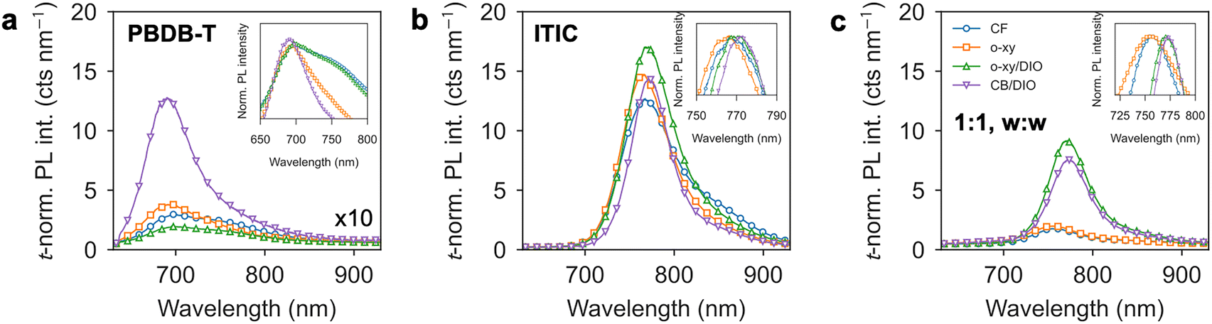 | ||
| Fig. 3 Thickness-normalized (t-normalized) PL intensity of (a) neat PBDB-T films; (b) neat ITIC films; and (c) the corresponding 1:1, w:w blend films. Insets correspond in all cases to normalized spectra and zoomed-in regions nearby the relevant peak positions. | ||
In the case of ITIC, the PL spectra are qualitatively similar across the different processing conditions with a main peak at ca. 765 nm dominating the emission together with a shoulder at ca. 850 nm (Fig. 3b). Quantitatively, the t-normalized PL is also similar in all processing cases (cf. PBDB-T). Nevertheless, upon normalization of the PL spectra by their maximum value a systematic shift of the main PL peak emission is observed (inset of Fig. 3b): CF and o-xy spectra show blue-shifted PL peak emission with respect to DIO-rich ITIC films. This observation matches with the GIWAXS diffractograms as far as the crystallization of ITIC is concerned: DIO-rich (DIO-absent) processing conditions lead to crystalline (non-crystalline) ITIC films. Thus, it is concluded that crystalline ITIC results in comparatively more red-shifted PL peak emission.
The most significant differences in terms of t-normalized PL intensities and shifts are, however, observed in the blend films (Fig. 3c), which are qualitatively dominated by the emission properties of the acceptor. The t-normalized PL spectra of films in which the crystallization of ITIC is evidenced (i.e., o-xy/DIO and CB/DIO, Fig. 1k and l) is bright and its peak maximum appears red-shifted (775 nm, inset in Fig. 3c). If we consider that the weigh concentration is 1:1, the blend is “diluted” by ca. 50% in the density of ITIC molecules and thus one would expect that the corresponding t-normalized PL is half that of the neat film. In this respect, for these two solvents, the degree of PL quenching by blending is really low. Conversely, when ITIC is not crystallized (i.e., CF and o-xy, Fig. 1i and j), the PL is quenched and blue-shifted up to 750 nm. A stronger PL quenching is explained as finer intermixing between donor and acceptor leads to a more efficient charge separation of the photogenerated excitons, with the (then separated) photogenerated charge carriers decaying non-radiatively (rather than radiatively by geminate recombination) after finite diffusion through either donor or acceptor domains (i.e., non-geminate recombination).
Grazing incidence small angle X-ray scattering (GISAXS) horizontal cuts agree with the PL data of blend films. GISAXS measurements offer enhanced sensitivity to electron density contrast in the low q region located between 0.1–1 nm−1, corresponding to scatterers located in the range of 6–60 nm in real space. Phase-separated domains with sharper interfaces between them increase the scattering contrast (i.e., the overall scattering intensity) in said length scales. Thus, the GISAXS profiles can be exploited to qualitatively assess how domain aggregation evolves upon different solvent processing and post-processing treatments: larger (smaller) domains increase (decrease) the scattering intensity at low q values. The GISAXS profiles shown in Fig. S7c and d (ESI†), for as-cast and annealed PBDB-T:ITIC blends indicate, thus, that spin-coated CF films feature the weakest scattering intensity, followed closely by spin-coated o-xy films (particularly after annealing). This signals a thorough donor:acceptor intermixing and small domain sizes in the corresponding blends. On the contrary, blends containing an ordered component (especially those containing crystalline ITIC after DIO addition) show the strongest scattering intensity, suggesting that large domains and sharp interfaces are formed across a scale of tens of nm. Actually, in all the studied neat and blend films, it is observed that films processed from DIO-rich ink formulations yield the highest scattering intensities.
Thus, a priori and based on straightforward PL measurements, it is expected that organic solar cells comprising PBDB-T:ITIC processed from either CF or o-xy will show a comparatively better performance than those processed from o-xy/DIO or CB/DIO. Interestingly, the PL experiments confirm that the aggregate state of the NFA solely controls the emissive properties of the film regardless the microstructural arrangement achieved by the donor polymer. In other words, an over-crystallized NFA such as ITIC processed from DIO-rich co-solvent formulations is per se and a priori detrimental for the OPV device performance in spite of the donor polymer reaching a suitable microstructure for charge photogeneration and transport.
Based on this argumentation, functional organic solar cells are processed and their performance benchmarked for all four co-solvent systems herein employed. OPV devices were constructed according to an inverted (n–i–p) device architecture (Fig. 4a) and their photoactive layer (PAL) doctor bladed to form lateral thickness gradients. This is part of a well-established methodology to accelerate35 the screening of optimum device conditions and enable the high-throughput evaluation of their PAL thickness dependence.36 From a collection of 98 OPV devices, the champion J–V curves and EQE spectra are shown in Fig. 4b and c, respectively, with their figures of merit listed in Table 2. Importantly, doctor bladed PBDB-T:ITIC 1:1 (w:w) blend films preserve the solvent-dependent microstructural organization argued from Fig. 1 for analogous spin-coated films, as indicated by their corresponding GIWAXS diffractograms (Fig. S8, ESI†).
 | ||
| Fig. 4 (a) Inverted (n–i–p) organic solar cell device structure used in this work. (b) Champion J–V curves and (c) champion EQE spectra of the OPV devices prepared using four different co-solvent formulations. | ||
| Solvent | Voc (V) | Jsc (mA cm−2) | FF (%) | PCE (%) | Rs (Ω cm−2) | Rsh (Ω cm−2) |
|---|---|---|---|---|---|---|
| CF | 0.89 | 16.06 | 67.92 | 9.76 | 4.81 | 895 |
| o-xy | 0.85 | 15.85 | 64.15 | 8.65 | 6.87 | 969 |
| o-xy/DIO | 0.90 | 8.94 | 48.50 | 3.88 | 19.1 | 638 |
| CB/DIO | 0.92 | 10.80 | 55.32 | 5.49 | 12.0 | 914 |
The PCE of the best OPV devices reaches a maximum of 9.76% as the PAL is processed using CF as unique solvent, including an open-circuit voltage (Voc) of 0.89 V, a short-circuit current density (Jsc) of 16.06 mA cm−2 and a competitive fill factor (FF) of 67.92%. Such a PCE is in line with existing reports on blade coated PBDB-T:ITIC solar cells showing a record PCE of 10% in inverted device architectures29 (Table S2, ESI†). The best o-xy device follows with 8.65% PCE while the DIO-rich counterparts show notably lower record PCE values of 3.88% (o-xy/DIO) and 5.49% (CB/DIO). In these latter cases, the performance downgrade is led by Jsc (ca. −40% with respect to CF), the FF (which stays below 56%), and the series resistance Rs, which is observed to suffer a 2- to 4-fold increase with respect to the best CF device. The EQE spectra are, however, qualitatively similar across processing solvents but their absolute values appear systematically downgraded in the DIO-rich scenarios (Fig. 4c). In the former cases (CF, o-xy), the EQE keeps reasonably flat around 50–55% from 400 to 780 nm excitation whereas in the unfavorable cases (o-xy/DIO, CB/DIO) the EQE does not exceed 40% at any wavelength. Overall, these observations suggest the formation of a suboptimal BHJ morphology in DIO-rich cases in which charges recombine before being extracted (Jsc, EQE), adding problems to their extraction (FF, EQE) and showing poor charge transport properties (Rs).
On the relationship between the device performance and the structural order deduced from the GIWAXS diffractograms (Fig. 1) and their integrated linecuts (Fig. S1, ESI†), it is herein confirmed that superior PCEs (9.76%, CF; 8.65%, o-xy) are achieved in BHJs where the acceptor is poorly crystalline and a largely mixed donor:acceptor morphology is formed. Additionally, PALs featuring highly-ordered acceptors (o-xy/DIO and CB/DIO) result in over-purified ITIC domains which severely downgrade the device performance. This occurs regardless the paracrystalline order achieved by the donor polymer (o-xy/DIO vs. CB/DIO). Actually, OPV devices in which the polymer domains show an enhanced paracrystalline order while keeping a vitrified acceptor (o-xy) show closer performance to the top performers (CF). In other words, the increase of the paracrystalline order of the polymer (CF vs. o-xy) has less quantitative influence on the device performance than the increase of the crystallinity of the acceptor does (o-xy vs. o-xy/DIO).
When the PV figures of merit are studied as a function of PAL thickness (Fig. 5), it is found that the PCE of the PBDB-T:ITIC blend (Fig. 5a) remains reasonably constant up to 200 nm in the most favorable cases (CF and o-xy). Such a property, together with the non-halogenated nature of o-xy and the competitive device performance shown against halogenated counterparts (Table S2, ESI†), grants remarkable interest on said blend for its up-scaling in thick form factors and inverted device architectures.37 In this context, high performing devices are needed for a minimum PAL thickness of ca. 200 nm,38 which is actually the case for PBDB-T:ITIC in this work. Nevertheless, for thicker PAL films (>200 nm), the PCE severely drops as a result of the downgraded FF first (Fig. 5d) and the lower Jsc later (>300 nm, Fig. 5b), thus suggesting limited mobility of the free charge carriers and their poor extraction at the contacts. When ITIC crystallizes (i.e., in the o-xy/DIO and CB/DIO cases), the PCE decreases steadily (linearly) as a function of PAL thickness. Notwithstanding, in all cases the Voc remains fairly invariant as a function of PAL thickness. This observation is in agreement with previous reports indicating that a rather constant Voc holds over wide PAL thickness intervals (0–400 nm).39,40 As the same inverted device architecture is maintained throughout this work, the quantitative Voc differences observed as a function of processing solvents (Table 2 and Fig. 5c) are solely ascribed to the different degrees of donor:acceptor phase separation achieved in each case. In this regard it is noted that the average Voc observed positively correlates with the GISAXS intensity attained at low q's in neat ITIC films only (Fig. S7b, ESI†) rather than in the as-cast (Fig. S7c, ESI†) or annealed blend films (Fig. S7d, ESI†). This suggests that a causal relationship might hold between larger acceptor domains, which increase the GISAXS scattering intensity in neat ITIC films, with higher Voc values in the corresponding blends and solar cells.
 | ||
| Fig. 5 Photovoltaic figures of merit as a function of the PAL thickness of the organic solar cells processed from the different co-solvent formulations used in this work. (a) PCE, (b) Jsc, (c) Voc and (d) FF. In all cases, the shaded areas correspond to the native spread of support vector regression models that were fitted to the experimental data to serve as guide-to-the-eye. | ||
The shelf stability of representative organic solar cells processed according to the four co-solvent formulations studied in this work was also evaluated. In this case, samples were stored in dark while in a nitrogen-filled glovebox for a period of 1322 days (>30000 hours). The results shown in Fig. 6 and Fig. S9 (ESI†), for devices of at least 100 nm in PAL thickness suggest that the CF-based counterpart (Fig. 6a) is actually the only variant that suffers an effective degradation over the time period of the assay. More particularly, the PCE of the CF device dropped from the initial 8.40% down to 6.72% after 1322 days, which implies that it only held 80% of the initial PCE. Such a downgrade was mainly driven by FF and Voc losses since Jsc remained fairly constant (Fig. S9, ESI†). Conversely, the o-xy device started with a PCE of 7.00% and ended with a PCE of 7.09% after 1322 days (Fig. 6b), so it remained virtually unaffected during shelf storage. In this case, however, the Jsc dropped down to 92% of its initial value yet its negative effect on the PCE was counterbalanced by a slightly improved Voc and FF (Fig. S9, ESI†). The remaining devices, namely o-xy/DIO (Fig. 6c) and CB/DIO (Fig. 6d), retained or even slightly improved their performance after prolonged shelf storage. The observation that the PCE is retained better in those BHJs which comprise a substantial fraction of crystalline material (either donor or acceptor in o-xy, o-xy/DIO and CB/DIO) rather than in a vitrified counterpart (CF) suggests that material crystallization might act slowing down the molecular migration and interdiffusion within the BHJ, which are here assumed to be the main sources of device instability while stored in dark in a nitrogen-filled glovebox. Overall, this observation further motivates the use of o-xy, with the added advantage of being a non-halogenated solvent, as the benchmark scenario for high-performing, thickness-tolerant and resilient blade coated OPV devices based on the PBDB-T:ITIC blend in future studies.
 | ||
| Fig. 6 J–V curves of the representative OPV devices processed from the different co-solvent formulations, as stored in the dark and in nitrogen for a period of 1322 days: (a) CF, (b) o-xy, (c) o-xy/DIO and (d) CB/DIO. Filled areas connect the first and last J–V curves. | ||
Conclusions
This work exploits a selection of (co-)solvents to individually tailor the aggregate state of the donor and acceptor materials in a state-of-the-art BHJ blend, namely, PBDB-T:ITIC. GIWAXS experiments confirm that the paracrystalline order of the polymer is enhanced when o-xy is used as primary solvent regardless the presence of additives such as DIO. On the contrary, DIO primarily and selectively affects the aggregate state of the acceptor as further verified by Raman spectroscopy, thus promoting the crystallization of ITIC in its phase I polymorph in the two co-solvent formulations herein tested: o-xy/DIO and CB/DIO. Both GIWAXS experiments and PL data confirm that over purified ITIC domains are formed which extensively phase-segregate the BHJ, resulting in a severely downgraded performance in the corresponding OPV devices. Notably, the PCE improves as the acceptor is forced to remain in a non-crystalline state, a phenomenon which occurs if the BHJ is processed from CF or o-xy as unique solvents. These results pinpoint to the critical role played by the aggregation of the acceptor as compared with the paracrystalline order achieved by the donor polymer, which is far less influential on the device performance. Both CF and o-xy-based, blade coated and inverted devices show competitive performance (record PCEs of 9.76% and 8.65%, respectively) and thickness tolerance up to 200 nm. These properties bring attention to the o-xy counterpart as being a non-halogenated solvent for its potential industrial up-scaling. Furthermore, the OPV devices herein studied show improved PCE retention during storage in inert atmosphere when they are processed from o-xy (virtually unaffected) rather than CF (80% of initial PCE) after 1322 days of assay. It is herein hypothesized that in resilient devices (o-xy, o-xy/DIO, CB/DIO) the molecular migration is mitigated due to the formation of partly semi-crystalline rather than largely vitrified BHJs. The present work raises important awareness on how the processing conditions, as determined by the choice of co-solvents in the pristine PAL ink formulation, might be adjusted to individually control the crystallinity of the donor:acceptor components and accordingly discern their isolated effect on the structure–function relationship and shelf stability in organic solar cells.Author contributions
X. R.-M. prepared the figures and drafted the manuscript. S. M. prepared the thin film samples. S. M. and J. M. characterized and analyzed those samples by X-ray diffraction. S. M. and A. H.-B. fabricated and characterized the performance of organic solar cells (J–V curves and EQEs). S. M., A. H.-B. and M. C.-Q. performed the Raman and PL measurements. X. R.-M. analyzed the Raman data. J. M. and M. C.-Q. secured funding, provided research infrastructure and supervised the work. All authors discussed, improved and reviewed the initial manuscript draft.Data availability
The data supporting this article is included in the main text and as part of the ESI.†Conflicts of interest
There are no conflicts of interest to declare.Acknowledgements
J. M. and S. M. thank financial support from the MICIU (PID2021-126243NB-I00). J. M. and X. R.-M. acknowledge funding from the European Research Council (Grant 101086805). GIWAXS experiments were performed at NCD-SWEET beamline at ALBA Synchrotron with the collaboration of ALBA staff. M. C.-Q. and A. H.-B. acknowledge support by the MICIU/AEI/10.13039/501100011033 for the “Severo Ochoa” program for Centres of Excellence CEX2023-001263-S and grants PID2021-128924OB-I00 and TED2021-131911B-I00. The authors acknowledge Universidade da Coruña/CISUG for the funding received for open access charge.References
- G. Zhang, F. R. Lin, F. Qi, T. Heumüller, A. Distler, H.-J. Egelhaaf, N. Li, P. C. Y. Chow, C. J. Brabec, A. K.-Y. Jen and H.-L. Yip, Chem. Rev., 2022, 122, 14180–14274 CrossRef CAS PubMed.
- R. Søndergaard, M. Hösel, D. Angmo, T. T. Larsen-Olsen and F. C. Krebs, Mater. Today, 2012, 15, 36–49 CrossRef.
- J. C. Blakesley, R. S. Bonilla, M. Freitag, A. M. Ganose, N. Gasparini, P. Kaienburg, G. Koutsourakis, J. D. Major, J. Nelson, N. K. Noel, B. Roose, J. S. Yun, S. Aliwell, P. P. Altermatt, T. Ameri, V. Andrei, A. Armin, D. Bagnis, J. Baker, H. Beath, M. Bellanger, P. Berrouard, J. Blumberger, S. A. Boden, H. Bronstein, M. J. Carnie, C. Case, F. A. Castro, Y.-M. Chang, E. Chao, T. M. Clarke, G. Cooke, P. Docampo, K. Durose, J. R. Durrant, M. R. Filip, R. H. Friend, J. M. Frost, E. A. Gibson, A. J. Gillett, P. Goddard, S. N. Habisreutinger, M. Heeney, A. D. Hendsbee, L. C. Hirst, M. S. Islam, K. D. G. I. Jayawardena, M. B. Johnston, M. Kauer, J. Kettle, J.-S. Kim, D. Lamb, D. Lidzey, J. Lim, R. MacKenzie, N. Mason, I. McCulloch, K. P. McKenna, S. B. Meier, P. Meredith, G. Morse, J. D. Murphy, C. Nicklin, P. Ortega-Arriaga, T. Osterberg, J. B. Patel, A. Peaker, M. Riede, M. Rush, J. W. Ryan, D. O. Scanlon, P. J. Skabara, F. So, H. J. Snaith, L. Steier, J. Thiesbrummel, A. Troisi, C. Underwood, K. Walzer, T. Watson, J. M. Walls, A. Walsh, L. D. Whalley, B. Winchester, S. D. Stranks and R. L. Z. Hoye, J. Phys. Energy, 2024, 6, 041501 CrossRef CAS.
- Life cycle assessment: ’HeliaSol® 436x-000, HeliaSol® 1270–6000.
- H. Chen, Y. Huang, R. Zhang, H. Mou, J. Ding, J. Zhou, Z. Wang, H. Li, W. Chen, J. Zhu, Q. Cheng, H. Gu, X. Wu, T. Zhang, Y. Wang, H. Zhu, Z. Xie, F. Gao, Y. Li and Y. Li, Nat. Mater., 2025, 24, 444–453 CrossRef CAS PubMed.
- Y. Sun, L. Wang, C. Guo, J. Xiao, C. Liu, C. Chen, W. Xia, Z. Gan, J. Cheng, J. Zhou, Z. Chen, J. Zhou, D. Liu, T. Wang and W. Li, J. Am. Chem. Soc., 2024, 146, 12011–12019 CrossRef CAS PubMed.
- H. Kang, G. Kim, J. Kim, S. Kwon, H. Kim and K. Lee, Adv. Mater., 2016, 28, 7821–7861 CrossRef CAS PubMed.
- M. Ghasemi, H. Hu, Z. Peng, J. J. Rech, I. Angunawela, J. H. Carpenter, S. J. Stuard, A. Wadsworth, I. McCulloch, W. You and H. Ade, Joule, 2019, 3, 1328–1348 CrossRef CAS.
- X. Xiao, N. Yi, G. Yao, J. Lu, S. Leng, F. Liu, M. Hu, Z. Yuan and W. Zhou, ACS Appl. Mater. Interfaces, 2020, 12, 58082–58093 CrossRef CAS PubMed.
- H. Zhao, H. B. Naveed, B. Lin, X. Zhou, J. Yuan, K. Zhou, H. Wu, R. Guo, M. A. Scheel, A. Chumakov, S. V. Roth, Z. Tang, P. Müller-Buschbaum and W. Ma, Adv. Mater., 2020, 32, 2002302 CrossRef CAS PubMed.
- T. Wang, G. Kupgan and J.-L. Brédas, Trends Chem., 2020, 2, 535–554 CrossRef CAS.
- C. Guo, D. Li, L. Wang, B. Du, Z. Liu, Z. Shen, P. Wang, X. Zhang, J. Cai, S. Cheng, C. Yu, H. Wang, D. Liu, C. Li and T. Wang, Adv. Energy Mater., 2021, 11, 2102000 CrossRef CAS.
- T. Wang and J.-L. Brédas, J. Am. Chem. Soc., 2021, 143, 1822–1835 CrossRef CAS PubMed.
- Q. Zhang, Z. Chen, W. Ma, Z. Xie and Y. Han, J. Mater. Chem. C, 2019, 7, 12560–12571 RSC.
- Z. Xiao, Y. Yuan, B. Yang, J. VanDerslice, J. Chen, O. Dyck, G. Duscher and J. Huang, Adv. Mater., 2014, 26, 3068–3075 CrossRef CAS PubMed.
- R. C. Kilbride, E. L. K. Spooner, E. J. Cassella, M. E. O’Kane, K. Doudin, D. G. Lidzey, R. Jones and A. J. Parnell, ACS Appl. Energy Mater., 2024, 7, 8401–8411 CrossRef CAS PubMed.
- X. Song, N. Gasparini and D. Baran, Adv. Electron. Mater., 2018, 4, 1700358 CrossRef.
- Q. He, W. Sheng, M. Zhang, G. Xu, P. Zhu, H. Zhang, Z. Yao, F. Gao, F. Liu, X. Liao and Y. Chen, Adv. Energy Mater., 2021, 11, 2003390 CrossRef CAS.
- L.-M. Wang, Q. Li, S. Liu, Z. Cao, Y.-P. Cai, X. Jiao, H. Lai, W. Xie, X. Zhan and T. Zhu, ACS Appl. Mater. Interfaces, 2020, 12, 24165–24173 CrossRef CAS PubMed.
- Y. Zhang, A. J. Parnell, F. Pontecchiani, J. F. K. Cooper, R. L. Thompson, R. A. L. Jones, S. M. King, D. G. Lidzey and G. Bernardo, Sci. Rep., 2017, 7, 44269 CrossRef PubMed.
- Y. Zhu, A. Gadisa, Z. Peng, M. Ghasemi, L. Ye, Z. Xu, S. Zhao and H. Ade, Adv. Energy Mater., 2019, 9, 1900376 CrossRef.
- H. Hu, M. Ghasemi, Z. Peng, J. Zhang, J. J. Rech, W. You, H. Yan and H. Ade, Adv. Mater., 2020, 32, 2005348 CrossRef CAS PubMed.
- N. Li, J. D. Perea, T. Kassar, M. Richter, T. Heumueller, G. J. Matt, Y. Hou, N. S. Güldal, H. Chen, S. Chen, S. Langner, M. Berlinghof, T. Unruh and C. J. Brabec, Nat. Commun., 2017, 8, 14541 Search PubMed.
- S. Marina, E. Gutierrez-Fernandez, J. Gutierrez, M. Gobbi, N. Ramos, E. Solano, J. Rech, W. You, L. Hueso, A. Tercjak, H. Ade and J. Martin, Mater. Horiz., 2022, 9, 1196–1206 RSC.
- L. Ye, H. Hu, M. Ghasemi, T. Wang, B. A. Collins, J.-H. Kim, K. Jiang, J. H. Carpenter, H. Li, Z. Li, T. McAfee, J. Zhao, X. Chen, J. L. Y. Lai, T. Ma, J.-L. Bredas, H. Yan and H. Ade, Nat. Mater., 2018, 17, 253–260 Search PubMed.
- M. Ghasemi, N. Balar, Z. Peng, H. Hu, Y. Qin, T. Kim, J. J. Rech, M. Bidwell, W. Mask, I. McCulloch, W. You, A. Amassian, C. Risko, B. T. O’Connor and H. Ade, Nat. Mater., 2021, 20, 525–532 CrossRef CAS PubMed.
- Y. Mao, W. Li, M. Chen, X. Chen, R. S. Gurney, D. Liu and T. Wang, Mater. Chem. Front., 2019, 3, 1062–1070 Search PubMed.
- W. Zhao, D. Qian, S. Zhang, S. Li, O. Inganäs, F. Gao and J. Hou, Adv. Mater., 2016, 28, 4734–4739 CrossRef CAS PubMed.
- L. Zhang, B. Lin, B. Hu, X. Xu and W. Ma, Adv. Mater., 2018, 30, 1800343 CrossRef PubMed.
- S. Marina, A. D. Scaccabarozzi, E. Gutierrez-Fernandez, E. Solano, A. Khirbat, L. Ciammaruchi, A. Iturrospe, A. Balzer, L. Yu, E. Gabirondo, X. Monnier, H. Sardon, T. D. Anthopoulos, M. Caironi, M. Campoy-Quiles, C. Müller, D. Cangialosi, N. Stingelin and J. Martin, Adv. Funct. Mater., 2021, 31, 2103784 CrossRef CAS.
- W. C. Tsoi, D. T. James, J. S. Kim, P. G. Nicholson, C. E. Murphy, D. D. C. Bradley, J. Nelson and J.-S. Kim, J. Am. Chem. Soc., 2011, 133, 9834–9843 CrossRef CAS PubMed.
- L. Ciammaruchi, O. Zapata-Arteaga, E. Gutiérrez-Fernández, J. Martin and M. Campoy-Quiles, Mater. Adv., 2020, 1, 2846–2861 RSC.
- J. Gao, W. Wang, S. Zhang, S. Xiao, C. Zhan, M. Yang, X. Lu and W. You, J. Mater. Chem. A, 2018, 6, 179–188 RSC.
- A. Harillo-Baños, X. Rodríguez-Martínez and M. Campoy-Quiles, Adv. Energy Mater., 2020, 10, 1902417 CrossRef.
- X. Rodríguez-Martínez, E. Pascual-San-José and M. Campoy-Quiles, Energy Environ. Sci., 2021, 14, 3301–3322 RSC.
- A. Sánchez-Díaz, X. Rodríguez-Martínez, L. Córcoles-Guija, G. Mora-Martín and M. Campoy-Quiles, Adv. Electron. Mater., 2018, 4, 1700477 CrossRef.
- N. Camaioni, C. Carbonera, L. Ciammaruchi, G. Corso, J. Mwaura, R. Po and F. Tinti, Adv. Mater., 2023, 35, 2210146 CrossRef CAS PubMed.
- D. Zhang, B. Fan, L. Ying, N. Li, C. J. Brabec, F. Huang and Y. Cao, SusMat, 2021, 1, 4–23 CrossRef CAS.
- A. A. A. Torimtubun, M. J. Alonso-Navarro, A. Quesada-Ramírez, X. Rodríguez-Martínez, J. L. Segura, A. R. Goñi and M. Campoy-Quiles, Sol. RRL, 2024, 8, 2400213 CrossRef CAS.
- S. Riera-Galindo, M. Sanz-Lleó, E. Gutiérrez-Fernández, N. Ramos, M. Mas-Torrent, J. Martín, L. López-Mir and M. Campoy-Quiles, Small, 2024, 2311735 CrossRef CAS PubMed.
Footnote |
| † Electronic supplementary information (ESI) available. See DOI: https://doi.org/10.1039/d5tc01473e |
| This journal is © The Royal Society of Chemistry 2025 |