Reconfigurable assemblies of Janus rods in AC electric fields†
Kundan
Chaudhary
a,
Jaime J.
Juárez
b,
Qian
Chen
b,
Steve
Granick
bc and
Jennifer A.
Lewis
*a
aSchool of Engineering and Applied Sciences and Wyss Institute for Biologically Inspired Engineering, Harvard University, Cambridge, MA, USA. E-mail: jalewis@seas.harvard.edu
bDepartment of Materials Science and Engineering and the Frederick Seitz Materials Research Laboratory, University of Illinois, Urbana, Illinois, USA
cDepartment of Physics and Department of Chemistry, University of Illinois, Urbana, Illinois, USA
First published on 12th November 2013
Abstract
We investigate the electric field-induced assembly of Janus colloids composed of silica rods patterned with gold patches in both side- and tip-coated motifs. These shape and chemically anisotropic particles assemble into reconfigurable chains, whose structure depends on patch location, AC electric field strength, and frequency.
The rational design of supracolloidal structures can be achieved through self- and directed assembly of shape and chemically anisotropic particles.1 Recent efforts have focused on fabricating homogeneous2 and Janus spheres,3 dumbbells,4 ellipsoids,5 and rods.6 Concurrently, studies have been carried out to investigate their self-assembly into precisely controlled clusters7,8 as well as their directed assembly into chains and more exotic structures in external fields.9–11
AC electric fields provide an additional pathway for guiding colloidal assembly via tunable parameters, such as the field strength and frequency.12 It is well known that even homogeneous spheres assemble into linear chains, and ultimately 2D crystals, that align with the direction of the applied electric field.13,14 By contrast, shape anisotropic colloids, such as ellipsoids, assemble into chains that deviate from parallel alignment with applied electric field direction.15 While Janus spheres composed of hemispherical metallic shells coated on either polymeric or silica spheres form staggered chains that align parallel to the electric field direction.9 Finite element modeling suggests that this configuration is energetically favored, because it allows their metallic shells to form a continuous conductive pathway. Most recently, Janus dumbbells composed of different lobes have been synthesized to study the effect of electric field driven assembly on shape and chemically anisotropic building blocks.10 Depending on their composition, these dumbbells either form chains with their major axes aligned parallel to the electric field direction over all observed frequencies or they form chains with their major axes oriented perpendicular or parallel to the electric field at low (1 kHz) and high (>1 MHz) frequencies, respectively.
In this paper, we investigate the reconfigurable assembly of colloidal Janus rods in AC electric fields. Specifically, we tune the patch location, electric field strength and frequency to create new supracolloidal structures. Beginning with the synthesis of pure silica rods,6 we produce two types of anisotropic patchy particles: side- and tip-coated Janus rods. We refer to the latter motif as Janus matchsticks.17 For the first time, we explore the assembly of metallodielectric colloidal rods in AC electric fields and find that they form complex chain-like structures not previously observed for Janus spheres or dumbbells with equally partitioned hydrophilic and hydrophobic patches.9,10 In addition, we use finite element modeling to calculate the electric field and electric energy distribution that drives their assembly into chain-like structures under the experimental conditions studied.
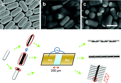
Fig. 1 shows the various building blocks used for electric field assembly. Homogeneous silica rods are synthesized to dimensions of 2.3 ± 0.2 μm in length (L) and 1.11 ± 0.08 μm in diameter (D) using a modified one-pot synthesis technique6 developed by Kuijk and co-workers. The initially synthesized rods are used as seed particles to grow additional layers of silica using Stöber method2 (Fig. 1a) allowing us to systematically tune their size and aspect ratio. Side-coated Janus rods are produced by settling under gravity a sub-monolayer of the silica rods on a hydrophilic glass substrate. Next, a thin coating of titanium (2 nm) is deposited onto the dried rods followed by 15 nm of gold (Au) using electron-beam evaporator. The rods are then subjected to selective Au etching to yield a uniform population of side-coated Janus rods (Fig. 1b).16 Finally, tip-coated Janus rods (matchsticks) are produced by a multi-step process reported previously (Fig. 1c), as described in the ESI.†17
Both homogeneous and Janus rod suspensions are placed within an electrode cell composed of two Au electrodes deposited on a glass substrate that are separated by 200 μm gap (Fig. 1d). A polydimethylsiloxane (PDMS) spacer of ∼2 mm in thickness is placed between the top cover and the substrate to prevent drying. The suspensions are subjected to an AC electric field of varying strength and frequency. We directly observe their assembly using bright-field optical microscopy.
We carried out two-dimensional (2D) numerical calculations of their electric energy to predict the behavior of each system. Specifically, the electric field and energy distributions around the Janus particles within these assemblies are determined using a COMSOL Multiphysics modeling package. Each Janus rod is modeled with a thin Au shell in their side- and tip-coated motifs surrounded by a 100 nm electric double layer (i.e., counterion shell). The experimental system is thus divided into silica rods, the Au coating on the rod surfaces, water media, and the counterion cloud. Additional details are provided in the ESI.†
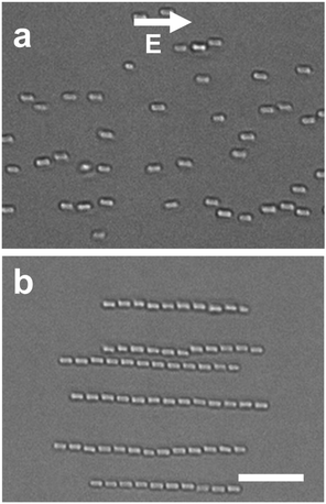
To probe the effect of shape anisotropy, we observed the assembly of homogeneous silica rods suspended in deionized (DI) water (Fig. 2) at AC electric field strength of 50 V mm−1 with varying frequency (100 kHz–30 MHz). The silica rods that have settled under gravity within the gap between electrodes exhibit rotational and translational motion. Rods with an aspect ratio, L/D, experience a torque, T = p × E, where the dipole moment, p ∼ L3E/ln(4L/D), and E is the applied electric field strength. Their major axes align along the electric field direction at all frequencies investigated. At 100 kHz, their electric double layers are polarized by electric field and dipoles form. Under these conditions, chain formation is not observed (Fig. 2a). At higher frequencies approaching ∼1 MHz, the dipolar rods assemble into linear chains (Fig. 2b, ESI Movie 1†), which align parallel to the applied AC electric field direction, akin to chaining behavior observed for homogeneous spheres.13
 | ||
| Fig. 2 Bright-field microscopy images of homogeneous silica rods in an applied electric field strength of 50 V mm−1 at (a) 100 kHz and (b) 30 MHz. The scale bar is 10 μm. | ||
The force experienced by neighboring rods as they form chains is proportional to the product of their dipole moments, F ∼ p2.18 The dipole moment, which represents the material polarization, is p = α·E, where α is the polarizability and E is the applied electric field strength. The rods are initially prevented from aggregating by electrostatic repulsion between themselves and glass substrate. However, chain-like structures form on the order of seconds upon application of the AC electric field. The particles within these chains quickly re-disperse in random orientations due to Brownian motion when the electric field is turned off. Their assembly is fully reversible, i.e., linear chains will form again upon applying an AC electric field.
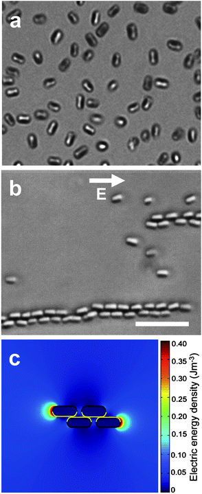
To explore the effects of shape and chemical anisotropy, we first investigated side-coated Janus rods with an Au patch along their major axis suspended in DI water (Fig. 3a). Unlike homogeneous silica rods, these Janus rods form staggered chains (Fig. 3b, ESI Movie 2†) in an AC electric field of 15 V mm−1 at all frequencies observed (100 kHz-30 MHz). A lower electric field strength is required to induce chaining of side-coated Janus rods, because their conductive Au coating has a high polarizability. Within each staggered chain, the rods adopt an orientation that promotes contact between the Au patches on adjacent rods, yet allows gaps between neighboring rods. Hence, a continuous metallic pathway, or “lane”, forms along the center of each staggered chain, in a manner akin to that observed for metallodielectric Janus spheres.9 The staggered chains composed of side-coated Janus rods are observed to span across the entire gap between electrodes. They assemble and disassemble reversibly within a few seconds as the AC electric field is turned on and off, respectively (ESI Movie 3†). Finite element modeling of a cluster composed of four side-coated Janus rods (Fig. 3c) reveals that there is a high electric energy distribution at the tips of each dangling rod. The overlapping staggered chain configuration observed experimentally is consistent with modeling results that show that this motif possesses the lowest potential energy amongst the different configurations evaluated (Fig. S1†).
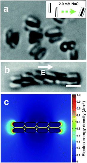
The chain structure formed by side-coated Janus rods in AC electric fields can be altered by first inducing doublet formation between rods suspended in salty water (2.9 mM NaCl), as shown in Fig. 4a. The electrostatic repulsion between these rods is fully screened at this ionic strength (relative to those in DI water), and their hydrophobic Au patches attract one another to form doublets. The Janus doublets assemble into flexible chains when subjected to an AC electric field strength of 20 V mm−1 at 100 kHz (Fig. 4b, ESI Movie 4†). The doublets retain their morphology as they form double linear chains. Each chain is similar to that formed by pure silica rods, although those required far higher frequencies (30 MHz) relative to the doublets (0.1 MHz). The electric field strength and frequency are comparable to those used to assemble individual side-coated Janus rods (Fig. 3b), however the chain structure is quite different. The location of Au patch within the interior of the Janus rod doublets prevents them from forming a staggered conformation. Finite element modeling of the chains formed by assembling four doublets (Fig. 4c) reveal the presence of attractive regions near the dangling doublet ends, which promote the formation of linear doublet chains. We are now investigating the minimum salt concentration required to induce doublet formation as well as retain this morphology during chaining in AC electric fields.
To further explore how patch location influences chain formation, we investigated the assembly of Janus matchsticks in DI water in an AC electric field strength of 50 V mm−1 at varying frequencies (Fig. 5). At 100 kHz, the Janus matchsticks align with their major axis parallel to the applied electric field direction (Fig. 5a). At 2 MHz, the rods begin to randomize (Fig. 5b). At even higher frequencies approaching 3.5 MHz, they assemble into staggered bilayers, in which individual rods are vertically oriented and the top layer is offset by a half period relative to the bottom layer (Fig. 5c, ESI Movie 5†). As the frequency increases, the Au patch plays an increasingly dominant role in these dipolar rods. The effective lengths of the Au patches along the minor and major axes are 761 ± 0.09 nm and 212 ± 0.05 nm, respectively, which leads to a larger dipole moment along the minor axis at higher frequencies. Akin to their linear counterparts, these bilayer chains are reconfigurable, i.e., their formation can be reversibly controlled on demand (ESI Movie 6†). The Janus matchsticks quickly re-disperse in solution adopting a random orientation after the field is turned off and then reassemble into staggered bilayer chains within a few seconds when an appropriate AC electric field is applied. Finite element modeling of a cluster composed of four tip-coated Janus rods (Fig. 5d), carried out at 50 V mm−1, 3.5 MHz, shows that the region of attraction shifts from bare silica to the Au patch along the minor axes. The bilayer chains possess the lowest potential energy amongst the different configurations evaluated (Fig. S2†). This configuration provides a continuous conductive pathway for Janus matchsticks system at higher frequencies where the Au patches along the minor axis of the Janus matchsticks align in an end-to-end fashion (Fig. 5c). However, even though a larger dipole exists along the minor axis of the Janus matchsticks, it is not sufficient to align isolated particles perpendicular to the applied electric field direction. Yet after they assemble into staggered bilayer chains, there is sufficient structural stability to retain a vertical orientation perpendicular to the applied electric field direction. Interestingly, there appears to be a critical cluster size required to stabilize this configuration. For example, we find that a two-particle cluster is unstable. Individual particles tend to join and break away from those clusters due to Brownian motion. By contrast, clusters containing three or more Janus matchsticks are relatively stable and, as more Janus matchsticks attach at the chain ends where the electric field intensity is larger, the bilayers grow in size. These observations give rise to two intriguing questions, i.e., what is the minimum patch size required to drive bilayer chain formation and how does the cluster stability depend on this parameter? Exploration of these phenomena is now underway through a combination of experiment and modeling.
Conclusions
We have studied the assembly of side- and tip-coated Janus rods in AC electric fields of varying strength and frequency. These colloidal building blocks possess both shape and chemical anisotropy that arises from their tunable patch type, size, and location. These model systems not only allow fundamental studies of reconfigurable supracolloidal assemblies, but yield new structures that may serve as novel templates for photonics, sensors, and battery electrodes.Acknowledgements
Colloidal rod synthesis was supported by the U.S. Department of Energy, Division of Materials Sciences under Award no. DE-FG02-07ER46471, through the Frederick Seitz Materials Research Laboratory at the University of Illinois at Urbana-Champaign. Colloidal rod assembly in AC electric fields and finite element modeling was supported by the AFOSR MURI award: FA9550-12-1-0471. We thank S. Gangwal and O. Velev for useful discussions regarding the modeling results.Notes and references
- S. C. Glotzer and M. J. Solomon, Nat. Mater., 2007, 6, 557 CrossRef PubMed
.
- W. Stöber, A. Fink and E. Bohn, J. Colloid Interface Sci., 1968, 26, 62 CrossRef
.
- L. Hong, S. Jiang and S. Granick, Langmuir, 2006, 22, 9495–9499 CrossRef CAS PubMed
.
- J. G. Park, J. D. Forster and E. R. Dufresne, J. Am. Chem. Soc., 2010, 132, 5960–5961 CrossRef CAS PubMed
.
- K. M. Keville, E. I. Franses and J. M. Caruthers, J. Colloid Interface Sci., 1991, 144, 103 CrossRef CAS
.
- A. Kuijk, A. van Blaaderen and A. Imhof, J. Am. Chem. Soc., 2011, 133, 2346–2349 CrossRef CAS PubMed
.
- V. N. Manoharan, M. T. Elsesser and D. J. Pine, Science, 2003, 301, 483–487 CrossRef CAS PubMed
.
- Q. Chen, J. K. Whitmer, S. Jiang, S. C. Bae, E. Luijten and S. Granick, Science, 2011, 331, 199 CrossRef CAS PubMed
.
- S. Gangwal, O. J. Cayre and O. D. Velev, Langmuir, 2008, 24, 13312–13320 CrossRef CAS PubMed
.
- D. Nagao, M. Sugimoto, A. Okada, H. Ishii, M. Konno, A. Imhof and A. van Blaaderen, Langmuir, 2012, 28, 6546–6550 CrossRef CAS PubMed
.
- J. Yan, K. Chaudhary, S. C. Bae, J. A. Lewis and S. Granick, Nat. Commun., 2013, 4, 1516 CrossRef PubMed
.
- A. Yethiraj, Soft Matter, 2007, 3, 1099–1115 RSC
.
- S. O. Lumsdon, E. W. Kaler and O. D. Velev, Langmuir, 2004, 20, 2108–2116 CrossRef CAS
.
- J. J. Juarez and M. A. Bevan, J. Chem. Phys., 2009, 131, 134704–134709 CrossRef PubMed
.
- J. P. Singh, P. P. Lele, F. Nettesheim, N. J. Wagner and E. M. Furst, Phys. Rev. E: Stat. Phys., Plasmas, Fluids, Relat. Interdiscip. Top., 2009, 79, 050401 CrossRef
.
- Q. Chen, E. Diesel, J. K. Whitmer, S. C. Bae, E. Luijten and S. Granick, J. Am. Chem. Soc., 2011, 133, 7725–7727 CrossRef CAS PubMed
.
- K. Chaudhary, Q. Chen, J. J. Juárez, S. Granick and J. A. Lewis, J. Am. Chem. Soc., 2012, 134, 12901–12903 CrossRef CAS PubMed
.
-
T. B. Jones, Electromechanics of Particles, Cambridge University Press, U.K., 1995 Search PubMed
.
Footnote |
| † Electronic supplementary information (ESI) available. See DOI: 10.1039/c3sm52418c |
| This journal is © The Royal Society of Chemistry 2014 |


