Efficient NIR-to-vis photon upconversion in binary rubrene films deposited by simplified thermal evaporation†
Edvinas
Radiunas
 a,
Lukas
Naimovičius
 a,
Steponas
Raišys
 a,
Augustina
Jozeliūnaitė
b,
Edvinas
Orentas
 b and
Karolis
Kazlauskas
 *a
*a
aInstitute of Photonics and Nanotechnology, Vilnius University, Saulėtekio av. 3, LT-10257 Vilnius, Lithuania. E-mail: karolis.kazlauskas@ff.vu.lt
bInstitute of Chemistry, Faculty of Chemistry and Geosciences, Vilnius University, Naugarduko 24, LT-03225 Vilnius, Lithuania
First published on 22nd March 2022
Abstract
Low-power NIR-to-vis upconversion (UC) of incoherent excitation mediated by triplet–triplet annihilation (TTA) has a variety of promising applications, e.g. in photovoltaics; however, these are strongly hampered by low UC efficiency in the solid state. The issue is mainly related to the most efficient rubrene annihilator (emitter) utilized for this spectral range, which experiences severe concentration quenching in films due to singlet fission (SF). Herein, a simplified thermal evaporation technique is introduced to alter the morphology of binary rubrene films without involving a singlet sink aiming to suppress SF and boost UC efficiency. Hot-plate evaporation of rubrene under ambient nitrogen on a Peltier-cooled substrate pre-coated with a sensitizer layer is demonstrated to significantly improve the FL quantum yield and triplet energy transfer after annealing, subsequently ramping UC quantum yield up to (1.2 ± 0.15)% (out of maximum 50%). This is at least twice as high as that found in any other binary NIR-UC film reported so far. Moreover, we find that the statistical probability (f factor) of producing a singlet from two triplets via TTA in amorphous rubrene films (f = 19.5%) is close to that estimated for rubrene in a solution. This finding infers a maximum UC yield of 1/2 × f ≈ 10% and explains why there are no reports on rubrene UC systems exceeding this value.
Introduction
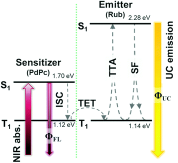
Growing research interest in photon energy upconversion (UC) attainable in organic materials via triplet–triplet annihilation (TTA) is stimulated by promising applications in photocatalysis,1–3 bioimaging,4 photovoltaics,5–14 targeted drug delivery,15,16etc.17–19 The inherent ability of TTA-UC to be driven by incoherent irradiation and at low power densities (∼mW cm−2)5,7,20 implies great opportunities for solar energy harvesting, since poorly utilized near-infrared (NIR) photons in solar cells can be readily converted into the visible radiation and reused thereafter for photocurrent generation.5,7 The general energy scheme depicting energy transfer processes in a typical TTA-UC system is shown in Fig. 1. Usually, TTA-UC is realized in binary systems composed of a sensitizer and an annihilator (emitter). The sensitizer is responsible for low energy photon absorption into the singlet state, conversion of the singlet excitation to triplet via intersystem crossing (ISC) and triplet energy transfer (TET) to the emitter. Meanwhile, the emitter ensures triplet migration until the two of them meet, promoting one of the triplets to a higher-energy singlet state via TTA. The whole process is finalized by the UC emission from the singlet state. Considering that each intermediate energy transfer step contributes to the UC quantum yield (ϕUC), it can be expressed as14,21,22 | (1) |
Challenging practical TTA-UC applications, such as in photovoltaics, demand high NIR-to-vis UC efficiency, preferably in the solid state.8,26 A fulfilment of the latter requirement remains an important issue that many research groups aim to overcome. It is evident that the vast majority of demonstrated solid-state UC systems operating in the NIR range (>700 nm) usually express very low ϕUC, typically <1%.14,26–32
Commonly exploited TTA emitters for the NIR spectral range are tetracenes,33–35 rubrenes,24,30,31,36–40 perylenes26,41 or diketopyrrolopyrroles.42 Most of these emitters are efficient in the liquid environment. Meanwhile, there is a lack of emitters with a low lying triplet-state that are fluorescent in the solid state.14 The best-performing NIR-to-vis UC systems demonstrated so far, both in solution and the solid state, rely on the rubrene (Rub) emitter.14
Previously, we demonstrated that in the Rub-based UC solutions ϕUC is limited to ∼7.8% due to the relatively low f factor (∼15.6%).22 In the solid-state, however, Rub additionally suffers from severe concentration quenching mainly attributed to singlet fission (SF), which results in a more than 60-fold drop in the fluorescence quantum yield (ϕFL). Thus, even the most efficient Rub-based UC films typically demonstrate one or two orders of magnitude lower ϕUC compared to those of UC solutions, where ϕFL of Rub is almost unity.
Generally, SF related losses can be mitigated by using two approaches, i.e. (i) molecular engineering, which relies on the chemical modification of the existing emitters or the introduction of alternative ones; and (ii) physical engineering based on altering the UC film composition or morphology.
Previously, we utilized a molecular engineering approach to introduce t-butyl substituents into Rub and improve the NIR-to-vis ϕUC in the solid films.43 It was also revealed that Rub modifications at the periphery do not inhibit TTA step; however, substituents linked directly to the tetracene core suppress TTA dramatically.44 The standard physical engineering approach to combat low ϕFL in Rub films and mitigate SF is to introduce the third component, i.e. a singlet exciton sink (collector), dibenzotetraphenylperiflanthene (DBP). Doping Rub films with a low concentration of DBP was reported to boost ϕFL by a factor of 20 due to the efficient FRET of upconverted singlets from Rub to DBP.27,45 Yet, the potential for altering the UC film morphology by employing different preparation techniques to address low ϕUC issues was not exploited to the fullest extent.
In this work, we demonstrate the potential of the physical engineering approach to boost the UC efficiency in the binary emitter/sensitizer films without involving an exciton sink. To prepare UC films, we introduce a simplified thermal evaporation technique (using a hot plate) in an inert atmosphere. The highly concentrated Rub films obtained in this way display an order of magnitude higher fluorescence quantum yield (ϕFL) compared to the films produced by solution-processing or sophisticated thermal deposition in a vacuum. Furthermore, we show that in these films the sensitizer and emitter are well dispersed and intermixed to result in an efficient triplet energy transfer (ϕTET). The improved ϕFL along with the efficient ϕTET results in a record-high ϕUC of the Rub-based binary solid-state systems, which is at least twice as high as that obtained in any other binary NIR-UC film reported so far.14,32,46
Experimental
Materials
Rubrene (Rub) was purchased from TCI. Polystyrene (PS) was purchased from Sigma-Aldrich. The synthesis of palladium phthalocyanine (PdPc) was published elsewhere.22Optical techniques
The absorption spectra of the investigated samples were recorded using a UV-vis-NIR spectrophotometer Lambda 950 (PerkinElmer). Fluorescence (FL) of the samples was excited at 485 nm either by using a 150 W xenon arc lamp (Oriel) coupled to a monochromator (Sciencetech), or by utilizing a continuous-wave semiconductor laser diode (Picoquant). Photon upconversion (UC) was induced by exciting at 730 nm using a 12 mW power continuous-wave semiconductor laser diode (Picoquant). Steady state FL and UC emission spectra were measured using a back-thinned CCD spectrometer PMA-12 (Hamamatsu). Fluorescence transients of the samples were measured by using a time-correlated single photon counting system PicoHarp 300 (Picoquant), which utilized a pulsed semiconductor laser diode (wavelength – 485 nm, pulse duration – 70 ps, repetition rate – 1 MHz) as an excitation source. Phosphorescence spectra in the NIR range were measured using a water-cooled iDus InGaAs 1.7 array detector (Andor). FL quantum yields (ϕFL) were estimated by utilizing an integrating sphere (Sphere Optics) coupled to the CCD spectrometer PMA-12 via an optical fiber; the xenon arc lamp was used as an excitation source. ϕUC was estimated by comparing the integral of the UC spectrum with that of the FL spectrum of the PdPc sensitizer with known quantum yield, as described previously.22 For strong UC signals both integrating sphere and comparative methods were used to ensure the reliability of the obtained values.Results and discussion
Due to the low-lying triplet state (T1) in the NIR region and 2 × T1 close to the singlet energy (S1) in the visible range, Rub became the standard emitter for NIR-to-vis photon upconversion.14,27,28,31,32,47,48 In fact, by far there are almost no alternative emitters capable of delivering comparable performance in the solid-state.14 Even though solution-processed Rub neat films have low ϕFL (∼1%), other similar TTA emitters with low triplet energy (T1 < 1.2 eV) are almost non-emissive, because of aggregation-caused quenching. Low ϕFL is disastrous, as it subsequently reduces ϕUC (eqn (1)). One of the main causes of low ϕFL in Rub films is singlet fission (SF), which is feasible due to the favorable energetics (S1 ≈ 2 × T1) of Rub. Lasting on a time-scale of picoseconds SF outcompetes radiative decay by opening the alternative deactivation channel for the singlets, i.e. splitting into two triplets. Depending on the local molecular environment, the emerged triplet pairs can rapidly undergo geminate triplet fusion or dissociate and either (i) decay non-radiatively, or (ii) diffuse and form encounter complexes at a much slower rate for non-geminate TTA.23,45,49,50It is well known that SF-associated losses are strongly related to the degree of crystallinity of the Rub films. The crystallinity can be altered by varying film preparation conditions and probed by monitoring their optical properties.
To minimize SF, amorphous Rub films with a chaotic molecular orientation and large average intermolecular distance must be produced. Biaggio et al. successfully exploited molecular beam deposition in a high vacuum to obtain amorphous Rub films.50 The films were virtually free from SF and showed mono-exponential fluorescence decay (τ = 16.4 ns) close to that of Rub in solution.50
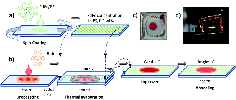
In the current study, diverse deposition conditions of emitter Rub are investigated to assess the impact of emitter morphology on ϕFL, and correspondingly ϕUC in the solid films. Featuring an appropriate energy level alignment, palladium phthalocyanine (PdPc) was chosen as a triplet sensitizer for the Rub.43Fig. 2a and b illustrates the step-by-step fabrication of UC films under investigation. In the first step, the sensitizer layer composed of an optically inert polymer matrix doped with low concentration (0.1 wt%) of PdPc was formed by spin-coating (Fig. 2a). Then Rub was deposited on top by using one of the four distinct thermal evaporation modes to result in the formation of the UC film (Fig. 2b). In the vacuum deposition mode, controlled thermal evaporation in a high vacuum (∼10−7 Torr) was used. This mode was previously reported to produce amorphous rubrene films and therefore served as a reference deposition mode.50 The remaining three modes were based on a simplified thermal evaporation of Rub (using the hot-plate) in ambient nitrogen. In the cold deposition mode, rubrene molecules were deposited on a Peltier cooled (−10 °C) substrate (Fig. 2b). This mode is expected to instantly freeze emitter molecules on the substrate, thus producing amorphous films. Aiming to quantify the effect of substrate cooling, cold-deposited films were annealed at 100 °C defining the post-annealing mode. Lastly, Rub evaporation on an uncooled substrate (naturally heated due to the close proximity of the evaporation source) was named the hot deposition mode.
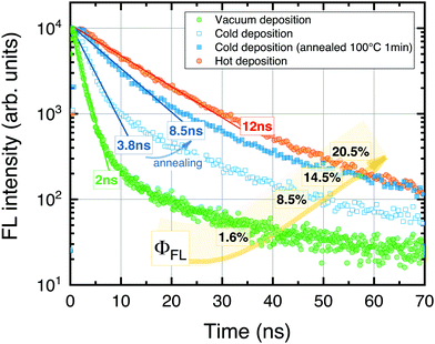
The UC films prepared at different conditions were initially evaluated by measuring FL transients and ϕFL (Fig. 3). The results clearly show high sensitivity to the Rub deposition mode. The FL transients consisted of the dominant prompt decay (fractional contribution of 70–90% to an overall decay) affected by SF and the minor slower decay component resembling natural decay of the isolated Rub species. The prompt component was described by a single-exponential decay profile to determine excited state lifetime. The shorter FL lifetime suggested an enhanced SF, and hence, a reduced ϕFL.
In the case of vacuum-deposited films, rapid decay with τ = 2 ns and low ϕFL (1.6%) was obtained. This was unexpected, since a vacuum-deposition previously was reported to result in amorphous films50 free from SF and with the FL lifetime similar to that of Rub in solution (τ = 16.4 ns).
Interestingly, prolonged decay (τ = 3.8 ns) as well as increased ϕFL up to 8.5% was obtained for the films fabricated using the cold deposition mode, indicating a more random molecular orientation and suppressed SF. Post-annealing of the UC films further extended the FL lifetime to 8.5 ns and improved ϕFL by almost 2-fold. Finally, the highest ϕFL of 20.5% along with the longest FL lifetime (τ = 12 ns) was determined for the films prepared in the hot deposition mode.
At first glance, the role of the heat treatment introduced during the film annealing or hot deposition is counterintuitive, since this is anticipated to facilitate Rub crystallization.51 Excess energy supplied in the form of heat may suffice to rearrange and crystallize Rub causing the formation of non-radiative SF centers. We note that the annealing temperature was set to correspond to the glass transition temperature (Tg) of the PS polymer employed. However, excess heat during the annealing can also promote Rub diffusion into the bottom sensitizer layer thereby diluting it and suppressing aggregation-caused FL quenching (see the inset of Fig. 4). Likewise, the hot deposition mode may result in a deeper Rub diffusion and thus stronger dilution more resembling the behavior of isolated Rub species or that of the purely amorphous film.
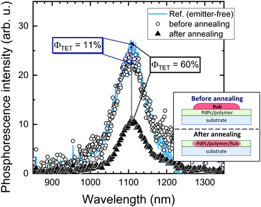
Further investigation in support of molecular diffusion involved studying the UC properties of the films via NIR excitation (730 nm) of the sensitizer. The improvement of UC efficiency was expected to be in correspondence with that of ϕFL. Indeed, the films of the lowest ϕFL fabricated using vacuum deposition and cold deposition modes exhibited barely detectable UC. On the other hand, annealed and hot-deposited films displayed bright UC. This result can be rationalized by considering the differences in the triplet energy transfer efficiency ϕTET (eqn (1)). The big temperature contrast during the cold deposition implies the formation of a bilayer UC film featuring a distinct boundary between the sensitizer and the emitter. As a result, most of the sensitizer triplets are generated far from the emitter species implying that short-range Dexter-type TET can only occur in a narrow interface region. Meanwhile, the promoted molecular diffusion during the film annealing causes mixing of the sensitizer and the emitter, thus reducing intermolecular separation and enhancing TET{PdPc → Rub}. Scanning electron microscopy (SEM) images supporting the mixing of the sensitizer and the emitter after annealing are provided in ESI† (see Fig. S1 and S2 and explanation therein). The mixing was also verified by evaluating ϕTET, where we compared phosphorescence intensity from the sensitizer PdPc of the cold deposited UC films with the same films after annealing (Fig. 4). For reference, we also measured phosphorescence of the emitter-free film containing only the sensitizer layer (polymer doped with PdPc). The experimental conditions ensured identical concentrations of PdPc and the sensitizer layer thickness of the tested films, thus enabling the intermixing effect of Rub and PdPc on TET to be addressed explicitly. The most intense PdPc phosphorescence peaked at 1106 nm was observed for the emitter-free film, since no TET{PdPc → Rub} was possible. Cold-deposited films expressed just a slightly reduced phosphorescence intensity due to inefficient ϕTET, whereas this intensity for the annealed films was severely decreased as a result of enhanced TET{PdPc → Rub}. Considering that
 | (2) |
Spatial variations of PdPc phosphorescence intensity and ϕTET in the annealed films are presented in the ESI† (see Fig. S4 and explanation therein). Taking into account the simplified thermal evaporation technique employed for the fabrication of the UC films, the reproducible ϕTET values could be obtained within the central area of ∼4 mm in size.
Even though the most efficient ϕFL was achieved using the hot deposition mode of Rub, the UC films prepared in this way had poor reproducibility. Specifically, Rub films were determined to be very sensitive to growth time and exhibited rapid crystallization already in the first growth stages (Fig. S5, ESI†). The morphological changes were accompanied by drastic spectral and FL decay time variations, i.e., additional aggregate-related FL band started emerging at 740 nm and τ reduced from 5.3 ns to 0.27 ns indicating increasing domination of SF.
Taking into account the reproducibility issues in the hot-deposition mode, further UC performance optimization was carried out for the films prepared by cold deposition followed by annealing. This deposition mode permitted control of the Rub thickness avoiding crystallization and allowed for consistent results (Fig. S6a, ESI†). Unlike neat Rub films obtained by the same method and showing increasing crystallization within a few weeks after fabrication, UC films fabricated by depositing Rub on top of the sensitizer-doped polymer layer followed by annealing were found to be stable. No signs of crystallization were detected several months after fabrication (see Fig. S7, ESI†) where FL lifetimes of the films are shown to remain constant at least within 240 days after film deposition). We attribute this to the dilution of Rub within the polymer layer, and thus suppression of rubrene aggregation.
Rub film thickness of approximately 600 nm, which corresponded to 3 min evaporation time was found to be optimal based on the UC intensity measurements (Fig. S6b, ESI†). Post-annealing of the films performed at 100 °C for ∼5 min yielded good film uniformity and bright UC emission, whereas longer annealing durations as well as higher temperatures induced strong crystallization (see Fig. S8, ESI†), and thus, were unacceptable for the UC film fabrication.
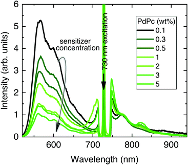
In the following UC optimization step, different sensitizer concentrations were tested while maintaining identical Rub deposition conditions (Fig. 5). Clearly, the increasing sensitizer concentration from 0.1 wt% to 5 wt% reduced the UC signal by 5 times suggesting enhanced upconverted energy back-transfer from Rub to PdPc. Although a higher sensitizer concentration is supposed to improve NIR absorption and reduce UC threshold, densely packed sensitizer molecules facilitate energy back-transfer diminishing the overall ϕUC.52 Aiming to maximize UC efficiency, the lowest PdPc concentration (0.1 wt%) was selected for further optimization. In fact, even lower concentration should potentially lead to a higher ϕUC; however, the subsequently decreased sensitizer absorption and thereby significantly weakened UC signal would compromise reliability of the results.
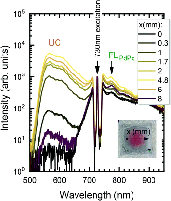
In the next step, the uniformity of the rubrene film deposited on top of PdPc-doped PS (sensitizer layer) was investigated. The measurements were carried out for different sensitizer layer thicknesses enabling the optimal one for maximal UC performance to be revealed. As discussed above, well mixed sensitizer and emitter films are required to have efficient ϕTET as well as high ϕFL of Rub. By assuming limited Rub diffusion into the sensitizer layer during the annealing, the too thick sensitizer layers could cause high absorption, yet likely reduced ϕUC due to lowered ϕTET. To verify this, we prepared a series of spin-coated sensitizer layers of different thickness, which was varied by altering mixture viscosity and spin coater speed. The film thickness was probed using AFM (see Fig. S9, ESI†). The Rub was deposited on top of the sensitizer layer through a circular metal spacer, forming a disk-shaped film (see the inset of Fig. 6). The prepared UC films were investigated by scanning across the surface in the x direction with the focused 730 nm laser beam and collecting the emission spectra as illustrated in Fig. 6.
The detailed scheme of this experiment is presented in Fig. S10 (ESI†). The measured spectra were analysed by discerning UC and FLPdPc spectral components peaking at 560 nm and 774 nm, respectively, and examining they relative intensities. Prior to FLPdPc analysis, the strong background signal due to the scattered excitation light and UC emission tail was subtracted.
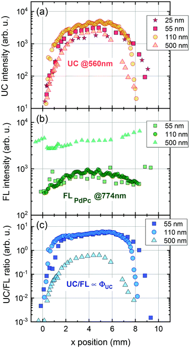
The UC intensity was found to exhibit a steep increase by almost 3 orders of magnitude with the excitation spot moving from the film edge to the centre (Fig. 7a). The intensity profile resembled Gaussian-like thickness distribution of the evaporated Rub and suggested that some critical thickness of the emitter is required to promote TTA in the Rub layer. Additionally, the sensitizer layer thickness of 110 nm was determined to be the optimal as giving rise to the highest UC intensity at these deposition conditions. Spatial distribution of FL intensity emanating from PdPc was found to be much more flat (Fig. 7b) in agreement with rather homogeneous sensitizer layers formed by spin-coating. These layers contained roughly the same amount of PdPc across the scanned area implying insignificant FL intensity variation vs the excitation coordinate. Taking into account that FLPdPc is not affected by the presence of Rub due to the energy level alignment, FLPdPc intensity should be proportional to the sensitizer layer thickness and PdPc concentration. Since the latter was fixed at 0.1 wt%, the thicker sensitizer layers (as more absorbing 730 nm radiation) resulted in the higher FLPdPc intensity. Importantly, considering that ϕFL of PdPc is constant across the film, this intensity can be used as an internal reference for the UC signal, thereby enabling the judgement of ϕUC from the UC and FLPdPc intensity ratio (Fig. 7c). For instance, although 25 nm and 500 nm-thick films showed similar UC intensity, the thicker films exhibited higher FLPdPc intensity correspondingly implying lower ϕUC. Unfortunately, the FLPdPc signal of 25 nm films was too weak to be measured; however, the data presented in Fig. 7c clearly suggest that thin sensitizer layers are more favorable for the realization of high ϕUC.
We note that the UC films with thin sensitizer layers (<100 nm) were difficult to measure as they were highly scattering and featured weak absorption, and hence, a relatively low UC intensity. These layers acted as a buffer for evaporated Rub and had a significant influence on the final UC film morphology. During the Rub deposition thin buffer experienced partial melting thereby forming a rough surface with enhanced scattering of the incident radiation. Taking this into account, a sensitizer layer thickness of 110 nm delivering one of the highest UC/FLPdPc ratios was selected to be optimal for UC films. Measurement of UC intensity vs excitation power density for these UC films enabled to determine the UC threshold of 1.4 W cm−2 (Fig. S11, ESI†), which was found to be similar to those of other rubrene-based solid-state UC systems.27,28,43,46 The optimized UC films were subjected to further evaluation of ϕUC by using the FLPdPc signal as an internal quantum yield reference (Fig. 8) as well as by means of an integrating sphere. The methodological details for the determination of ϕUC using an internal reference are provided in the ESI.†
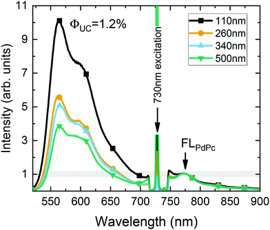
Fig. 8 illustrates the UC spectrum of the optimized UC film containing a 110 nm-thick sensitizer layer. Additional spectra of UC films with varying sensitizer layer thickness, prepared under otherwise the same conditions, are also shown for comparison. The UC spectra were normalized to the FLPdPc peak intensity so that UC intensity would correspond to ϕUC, as discussed earlier. Based on the independent measurements of UC films with different sensitizer layer thicknesses, yet with a fixed PdPc concentration of 0.1 wt%, the FL quantum yield of PdPc was determined (ϕPdPcFL = 0.1%). The reproducibility data of ϕPdPcFL tested for different films are included in the ESI.† Essentially, the data confirmed the average ϕPdPcFL to be 0.1% with a standard deviation of 0.03%.
Using this value as an internal reference, we could roughly deduce ϕUC to increase from 0.4% to 1% with decreasing sensitizer layer thickness from 500 to 110 nm (Fig. 8). The obtained ϕUC were confirmed by the measurements in the integrating sphere, where the most efficient UC film exhibited ϕUC = (1.2 ± 0.15)% (out of maximum 50%).
A slight underestimation of ϕUC by using an internal reference method can be explained by the strong background signal in the spectral region of FLPdPc due to the intense long-wavelength tail of UC emission. The accurate subtraction of such a strong background is complicated, which results in artificially increased FLPdPc intensity, and subsequently, somewhat reduced ϕUC. The calculated relative error for ϕUC in the case of the internal reference method was 32% (see the ESI†) implying that ϕUC values obtained by both methods agree well within these errors.
ϕ UC of (1.2 ± 0.15)% attained in this work represents a 17-fold improvement over our previous spin-coated DBP-doped rubrene films43 and at least a 2-fold improvement in respect to the most efficient binary rubrene-based solid-state systems reported to date (ϕUC ≈ 0.3–0.5%).14,29,46
We also note that the obtained ϕUC of the binary film approaches the highest efficiency value (ϕUC = 2%) achieved for the ternary UC film, additionally containing the DBP exciton sink.46 This reduces the gap in the performance of binary and ternary systems, minimizing the demand for the third component (singlet exciton sink) and stressing the importance of the UC film morphology rather than energetics of individual molecules.
Inserting the maximum efficiency values of the energy transfer/conversion processes determined for our UC films in eqn (1), the probability factor f for rubrene in the solid state can be estimated. Thus, taking into consideration that ϕFL = 20.5% (Fig. 3), ϕTET = 60% (Fig. 4), and ϕISC = 100% for palladium phthalocyanine-based sensitizers,22,39,41ϕTTA ≈ 100% in the TTA domination regime and that the maximal ϕUC = 1.2%, the statistical probability f to generate a singlet from two triplets via TTA is 19.5%. The confirmation for the deactivation occurring totally through the second-order path (ϕTTA ≈ 100%) achieved under excitation density of 100 W cm−2, i.e., well exceeding UC threshold is provided in the ESI.†
Interestingly, the obtained f factor is close to that estimated for rubrene in a solution (15.5%).22 This can be justified by the similar energy level alignment of rubrene in the different environment (solution or amorphous-like film) supporting the finding that the statistical probability of creating a singlet from two triplets via TTA should be in the range of 15–20%. We note that f estimated by us in the TTA-dominating conditions under continuous-wave excitation is 3–4 times lower as compared to that obtained under femtosecond pulsed-laser excitation conditions.38 The obtained f value implies a maximum ϕUC of 1/2 × f ≈ 10% for rubrene UC systems, which is reasonable, since no higher ϕUC has been demonstrated so far.14,27–32,46,53
Conclusions
In summary, this work addresses the low UC quantum yield issue in binary emitter/sensitizer films with rubrene serving as the annihilator (emitter). The issue is known to be related to detrimental singlet fission (SF) in highly concentrated rubrene films causing dramatic degradation of the FL quantum yield and subsequent reduction of UC efficiency. To cope with this problem, we offer an altering UC film morphology by exploiting different rubrene deposition techniques so as to suppress SF-promoting rubrene crystallization. From a variety of deposition modes explored, the simplified thermal evaporation of rubrene in ambient nitrogen using a hot plate delivered the features (highest FL quantum yield and longest FL lifetime) that most resemble those of an amorphous rubrene film. Explicitly, rubrene evaporation on a Peltier-cooled substrate pre-coated with a sensitizer layer and later annealing resulted in enhanced FL quantum yield (ϕFL ≈ 15%) and triplet energy transfer (ϕTET = 60%), which enabled reaching a record-high NIR-to-vis UC quantum yield of (1.2 ± 0.15)% (out of a maximum of 50%). The attained UC yield is at least 2-fold higher than for any other binary UC film reported so far that is capable of upconverting NIR radiation (>700 nm). Furthermore, the f factor describing the probability for a singlet to be created from two triplets via TTA in rubrene films (f = 19.5%) was found to be close to that estimated for rubrene in a solution.22 Assuming all the intermediate energy transfer processes are 100% efficient, the latter result implies a maximum UC quantum yield of 1/2 × f ≈ 10% thereby also explaining why there are no reports on rubrene UC systems exceeding this value.Conflicts of interest
There are no conflicts to declare.Acknowledgements
The research was funded by the European Social Fund (Project No. 09.3.3-LMT-K-712-01-0084) under a grant agreement with the Research Council of Lithuania (LMTLT).Notes and references
- B. D. Ravetz, A. B. Pun, E. M. Churchill, D. N. Congreve, T. Rovis and L. M. Campos, Nature, 2019, 565, 343–346 CrossRef CAS PubMed
.
- R. S. Khnayzer, J. Blumhoff, J. A. Harrington, A. Haefele, F. Deng and F. N. Castellano, Chem. Commun., 2011, 48, 209–211 RSC
.
- A. L. Hagstrom, S. Weon, W. Choi and J.-H. Kim, ACS Appl. Mater. Interfaces, 2019, 11, 13304–13318 CrossRef CAS PubMed
.
- Y. I. Park, K. T. Lee, Y. D. Suh and T. Hyeon, Chem. Soc. Rev., 2015, 44, 1302–1317 RSC
.
- J. Pedrini and A. Monguzzi, J. Photonics Energy, 2017, 8, 022005 Search PubMed
.
- L. Frazer, J. K. Gallaher and T. W. Schmidt, ACS Energy Lett., 2017, 2, 1346–1354 CrossRef CAS
.
- T. F. Schulze and T. W. Schmidt, Energy Environ. Sci., 2015, 8, 103–125 RSC
.
- V. Gray, K. Moth-Poulsen, B. Albinsson and M. Abrahamsson, Coord. Chem. Rev., 2018, 362, 54–71 CrossRef CAS
.
- A. Khare, J. Alloys Compd., 2019, 153214 Search PubMed
.
- Y. Y. Cheng, B. Fückel, R. W. MacQueen, T. Khoury, R. G. C. R. Clady, T. F. Schulze, N. J. Ekins-Daukes, M. J. Crossley, B. Stannowski, K. Lips and T. W. Schmidt, Energy Environ. Sci., 2012, 5, 6953–6959 RSC
.
- R. A. S. Ferreira, S. F. H. Correia, A. Monguzzi, X. Liu and F. Meinardi, Mater. Today, 2020, 33, 105–121 CrossRef
.
- J. C. Goldschmidt and S. Fischer, Adv. Opt. Mater., 2015, 3, 510–535 CrossRef CAS
.
- J. Zhou, Q. Liu, W. Feng, Y. Sun and F. Li, Chem. Rev., 2015, 115, 395–465 CrossRef CAS PubMed
.
- P. Bharmoria, H. Bildirir and K. Moth-Poulsen, Chem. Soc. Rev., 2020, 49, 6529–6554 RSC
.
- L. Huang, Y. Zhao, H. Zhang, K. Huang, J. Yang and G. Han, Angew. Chem., Int. Ed., 2017, 56, 14400–14404 CrossRef CAS PubMed
.
- Q. Liu, W. Wang, C. Zhan, T. Yang and D. S. Kohane, Nano Lett., 2016, 16, 4516–4520 CrossRef CAS PubMed
.
- D. Yildiz, C. Baumann, A. Mikosch, A. J. C. Kuehne, A. Herrmann and R. Göstl, Angew. Chem., Int. Ed., 2019, 58, 12919–12923 CrossRef CAS PubMed
.
- S.-W. Liu, C.-C. Lee, C.-H. Yuan, W.-C. Su, S.-Y. Lin, W.-C. Chang, B.-Y. Huang, C.-F. Lin, Y.-Z. Lee, T.-H. Su and K.-T. Chen, Adv. Mater., 2015, 27, 1217–1222 CrossRef CAS PubMed
.
- Y. Zhou, S.-T. Han, X. Chen, F. Wang, Y.-B. Tang and V. a. L. Roy, Nat. Commun., 2014, 5, 4720 CrossRef CAS PubMed
.
- T. Jia, Q. Wang, M. Xu, W. Yuan, W. Feng and F. Li, Chem. Commun., 2021, 57, 1518–1521 RSC
.
- Y. Zhou, F. N. Castellano, T. W. Schmidt and K. Hanson, ACS Energy Lett., 2020, 2322–2326 CrossRef CAS
.
- E. Radiunas, S. Raišys, S. Juršėnas, A. Jozeliūnaitė, T. Javorskis, U. Šinkevičiūtė, E. Orentas and K. Kazlauskas, J. Mater. Chem. C, 2020, 8, 5525–5534 RSC
.
- D. G. Bossanyi, Y. Sasaki, S. Wang, D. Chekulaev, N. Kimizuka, N. Yanai and J. Clark, JACS Au, 2021, 1, 2188–2201 CrossRef CAS PubMed
.
- Y. Y. Cheng, T. Khoury, R. G. C. R. Clady, M. J. Y. Tayebjee, N. J. Ekins-Daukes, M. J. Crossley and T. W. Schmidt, Phys. Chem. Chem. Phys., 2009, 12, 66–71 RSC
.
- S. Hoseinkhani, R. Tubino, F. Meinardi and A. Monguzzi, Phys. Chem. Chem. Phys., 2015, 17, 4020–4024 RSC
.
- K. M. Felter, M. C. Fravventura, E. Koster, R. D. Abellon, T. J. Savenije and F. C. Grozema, ACS Energy Lett., 2019, 124–129 Search PubMed
.
- M. Wu, D. N. Congreve, M. W. B. Wilson, J. Jean, N. Geva, M. Welborn, T. Van Voorhis, V. Bulović, M. G. Bawendi and M. A. Baldo, Nat. Photonics, 2016, 10, 31–34 CrossRef CAS
.
- M. Wu, J. Jean, V. Bulović and M. A. Baldo, Appl. Phys. Lett., 2017, 110, 211101 CrossRef
.
- S. Amemori, Y. Sasaki, N. Yanai and N. Kimizuka, J. Am. Chem. Soc., 2020, 142, 8057–8058 CrossRef CAS PubMed
.
- L. Nienhaus, J.-P. Correa-Baena, S. Wieghold, M. Einzinger, T.-A. Lin, K. E. Shulenberger, N. D. Klein, M. Wu, V. Bulović, T. Buonassisi, M. A. Baldo and M. G. Bawendi, ACS Energy Lett., 2019, 4, 888–895 CrossRef CAS
.
- L. Nienhaus, M. Wu, N. Geva, J. J. Shepherd, M. W. B. Wilson, V. Bulović, T. Van Voorhis, M. A. Baldo and M. G. Bawendi, ACS Nano, 2017, 11, 7848–7857 CrossRef CAS PubMed
.
- A. Abulikemu, Y. Sakagami, C. Heck, K. Kamada, H. Sotome, H. Miyasaka, D. Kuzuhara and H. Yamada, ACS Appl. Mater. Interfaces, 2019, 11, 20812–20819 CrossRef CAS PubMed
.
- C. J. Imperiale, P. B. Green, E. G. Miller, N. H. Damrauer and M. W. B. Wilson, J. Phys. Chem. Lett., 2019, 10, 7463–7469 CrossRef CAS PubMed
.
- S. N. Sanders, M. K. Gangishetty, M. Y. Sfeir and D. N. Congreve, J. Am. Chem. Soc., 2019, 9180–9184 CrossRef PubMed
.
- K. J. Fallon, E. M. Churchill, S. N. Sanders, J. Shee, J. L. Weber, R. Meir, S. Jockusch, D. R. Reichman, M. Y. Sfeir, D. N. Congreve and L. M. Campos, J. Am. Chem. Soc., 2020, 142, 19917–19925 CrossRef CAS PubMed
.
- V. Yakutkin, S. Aleshchenkov, S. Chernov, T. Miteva, G. Nelles, A. Cheprakov and S. Baluschev, Chem. – Eur. J., 2008, 14, 9846–9850 CrossRef CAS PubMed
.
- T. N. Singh-Rachford and F. N. Castellano, J. Phys. Chem. A, 2008, 112, 3550–3556 CrossRef CAS PubMed
.
- Y. Y. Cheng, B. Fückel, T. Khoury, R. G. C. R. Clady, M. J. Y. Tayebjee, N. J. Ekins-Daukes, M. J. Crossley and T. W. Schmidt, J. Phys. Chem. Lett., 2010, 1, 1795–1799 CrossRef CAS
.
- J. Han, F. Zhang, J. You, Y. Hiroaki, S. Yamada, T. Morifuji, S. Wang and X. Li, Photochem. Photobiol. Sci., 2017, 16, 1384–1390 CrossRef CAS PubMed
.
- A. S. Bieber, Z. A. VanOrman, S. Wieghold and L. Nienhaus, J. Chem. Phys., 2020, 153, 084703 CrossRef CAS PubMed
.
- Y. Che, W. Yang, G. Tang, F. Dumoulin, J. Zhao, L. Liu and Ü. İşci, J. Mater. Chem. C, 2018, 6, 5785–5793 RSC
.
- A. B. Pun, L. M. Campos and D. N. Congreve, J. Am. Chem. Soc., 2019, 141, 3777–3781 CrossRef CAS PubMed
.
- E. Radiunas, M. Dapkevičius, S. Raišys, S. Juršėnas, A. Jozeliūnaitė, T. Javorskis, U. Šinkevičiūtė, E. Orentas and K. Kazlauskas, Phys. Chem. Chem. Phys., 2020, 22, 7392–7403 RSC
.
- E. Radiunas, M. Dapkevičius, L. Naimovičius, P. Baronas, S. Raišys, S. Juršėnas, A. Jozeliūnaitė, T. Javorskis, U. Šinkevičiūtė, E. Orentas and K. Kazlauskas, J. Mater. Chem. C, 2021, 9, 4359–4366 RSC
.
- D. G. Bossanyi, Y. Sasaki, S. Wang, D. Chekulaev, N. Kimizuka, N. Yanai and J. Clark, J. Mater. Chem. C, 2022, 10, 4684–4696 RSC
.
- M. Kinoshita, Y. Sasaki, S. Amemori, N. Harada, Z. Hu, Z. Liu, L. K. Ono, Y. Qi, N. Yanai and N. Kimizuka, ChemPhotoChem, 2020, 4, 5271–5278 CrossRef CAS
.
- S. R. Pristash, K. L. Corp, E. J. Rabe and C. W. Schlenker, ACS Appl. Energy Mater., 2020, 3, 19–28 CrossRef CAS
.
- S. Wieghold, A. S. Bieber, Z. A. VanOrman and L. Nienhaus, J. Phys. Chem. Lett., 2019, 10, 3806–3811 CrossRef CAS PubMed
.
- K. Seki, T. Yoshida, T. Yago, M. Wakasa and R. Katoh, J. Phys. Chem. C, 2021, 125, 3295–3304 CrossRef CAS
.
- D. M. Finton, E. A. Wolf, V. S. Zoutenbier, K. A. Ward and I. Biaggio, AIP Adv., 2019, 9, 095027 CrossRef
.
- S.-W. Park, J.-M. Choi, K. H. Lee, H. W. Yeom, S. Im and Y. K. Lee, J. Phys. Chem. B, 2010, 114, 5661–5665 CrossRef CAS PubMed
.
- N. Geva, L. Nienhaus, M. Wu, V. Bulović, M. A. Baldo, T. Van Voorhis and M. G. Bawendi, J. Phys. Chem. Lett., 2019, 10, 3147–3152 CrossRef CAS PubMed
.
- L. Wang, J. J. Yoo, T.-A. Lin, C. F. Perkinson, Y. Lu, M. A. Baldo and M. G. Bawendi, Adv. Mater., 2021, e2100854 CrossRef PubMed
.
Footnote |
| † Electronic supplementary information (ESI) available. See DOI: 10.1039/d1tc05332a |
| This journal is © The Royal Society of Chemistry 2022 |

