DOI:
10.1039/D3MA00648D
(Paper)
Mater. Adv., 2024,
5, 2253-2259
Generation of time-multiplexed chiroptical information from multilayer-type luminescence-based circular polarization conversion films†
Received
4th September 2023
, Accepted 28th December 2023
First published on 29th December 2023
Abstract
Circularly polarized (CP) light generated from photoluminescence (PL) has great potential for the transmission of diverse forms of optical information including light intensity (brightness), spectral profile (color), and polarization (left-handed (LH)/right-handed (RH)), as well as temporal information corresponding to the PL lifetime of the CP light source. However, a systematic approach to the design of CP light-generating materials for the conveyance of time-multiplexed chiroptical information has not yet been reported. Herein, we demonstrate a novel approach to time-multiplexing chiroptical information using multilayered luminescence-based CP convertors comprising two linearly polarized luminescence (LPL) films with different PL lifetimes and a quarter-wave retardation film. We prepared LPL films with short and long PL lifetimes by stretching films comprising poly[2-methoxy-5-(2-ethylhexyloxy)-1,4-phenylenevinylene] (MEH-PPV) and CdSe/CdS core/shell quantum rod (QR) luminogens, respectively. We then fabricated four types of multilayered luminescence-based CP convertors by laminating the LPLMEH-PPV and LPLQR films with quarter-wave retardation films, so that the azimuthal angles between the polarization axes of the LPL films and the fast axes of the quarter-wave films differed in each case. The resulting CP light comprised short- and long-lifetime components. Subsequently, we used a time-resolved spectroscopic technique to extract time-multiplexed chiroptical information from changes in the time-course of the spectral profile of the LH- and RH-CP light. The time-varying of CP light profiles were thereby read-out as time-multiplexed chiroptical information. Our findings will pave the way for the design of CP light-generating materials for conveying time-multiplexed chiroptical information.
Introduction
Polarized light has great potential for the delivery of information because it has variable characteristics such as intensity (brightness), wavelength (color), and polarization (linear and/or circular). In contrast to linearly polarized (LP) light, which conveys information according to the plane of propagation (vertical (v) or horizontal (h)), circularly polarized (CP) light conveys information according to the direction of rotation of the polarization plane (left-handed (LH) or right-handed (RH)). The rotational direction of the polarization plane is immutable, regardless of the angle between the sender and the receiver of optical information. Therefore, CP light is now considered potentially useful for various applications, such as anti-counterfeit printing and optical data storage.1 In particular, CP light originating from photoluminescence (PL), including circularly polarized luminescence (CPL),2 has the following distinctive advantages. First, optical information is concealed in visible light, whereas it is apparent in UV radiation. Second, the PL mechanism enables the multiplexing of optical information by the simple addition of other luminogens (summation of light), whereas the light absorption mechanism has a theoretical limitation with regard to the addition of other absorbers owing to a decrease in light intensity (subtraction of light). Third, the selection of luminogens with different PL lifetimes makes it theoretically possible to multiplex temporal information as an additional parameter (Fig. 1c). Time-resolved spectroscopy is a powerful tool for extracting time-multiplexed optical information. Time-resolved CPL has been studied for more than three decades.3 Recent remarkable progress in CPL spectroscopy has enabled the detection of time-dependent CPL spectral changes on a timescale of less than a nanosecond.4 Such rapid CPL detection is accomplished using a simple quarter-wave plate instead of a photoelastic modulator (PEM) being capable of directly detecting small differences between LH- and RH-CP light intensities. Consequently, most research in this field has been conducted using a few CP light sources that produce high-intensity light with a high degree of polarization, such as chiral Eu(III) complexes. Therefore, CP light-generating materials for multiplexing optical information require certain capabilities. They must be capable of generating high-intensity light with a high degree of circular polarization, and must have high levels of wavelength and PL lifetime tunability. However, a systematic approach that satisfies all the requirements described above has not yet been reported.
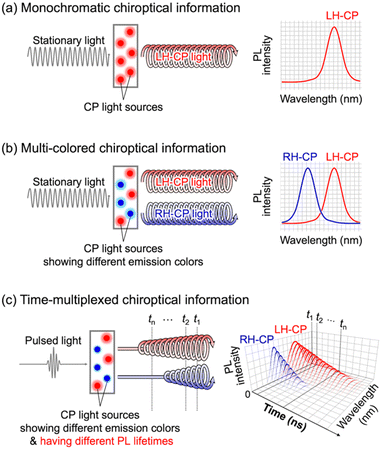 |
| | Fig. 1 Schematic illustration of (a) monochromatic and (b) multi-colored chiroptical information detected by steady-state PL spectroscopy, and (c) time-multiplexed chiroptical information detected by time-resolved PL spectroscopy. | |
We have previously reported that high-intensity CP light with a high degree of polarization can be generated by a luminescence-based CP convertor comprising a linearly polarized luminescence (LPL) film and a quarter-wave retardation film.5 The key to this approach is the use of LPL. The intensity, spectral pattern, and polarization degree of the CP light can be tuned by selecting the appropriate LPL materials. The degree of linear polarization (PLP-lum) depends on the orientation of the electronic transition dipole moment in the LPL material, and it behaves completely independently of the PL quantum yield (ϕ). Therefore, in theory both high ϕ and high PLP-lum values can be achieved by the selection of an appropriate luminogen and correct orientation of the dipole moment in the LPL material, in contrast to circularly polarized luminescence (CPL), which exhibits a trade-off correlation of these values.6 LPL with a high PLP-lum value can be directly converted to CP light while retaining a large degree of polarization. It is possible to determine the sign of the CP light (LH or RH) by selecting the angle (−45° or +45°, respectively) between the polarization plane of the LPL film and the fast axis of the quarter-wave retardation film. Furthermore, various types of optical information represented by PL intensity, peak position, polarization, and lifetime can be systematically multiplexed by laminating various LPL films with different optical properties.
Herein, we introduce a novel approach to time-multiplexing chiroptical information using multi-layered luminescence-based CP convertors comprising two LPL films with different PL spectral profiles and PL lifetimes (Fig. 2). The generated time-multiplexed chiroptical information is extracted by time-resolved spectroscopy with classical CP detection (see the ESI†). In the present paper, we demonstrate the generation of time-varying spectral profiles of LH- and RH-CP light and its read-out as temporal chiroptical information.
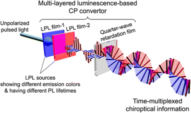 |
| | Fig. 2 Schematic illustration of a multi-layered luminescence-based CP convertor for generating time-multiplexed chiroptical information. | |
Results and discussion
In the present study, we selected poly[2-methoxy-5-(2-ethylhexyloxy)-1,4-phenylenevinylene] (MEH-PPV, Fig. 3a) and a CdSe/CdS core/shell quantum rod (QR, Fig. 3b) as luminogens with different PL lifetimes. Because these luminogens have PL spectra with similar emission ranges (approximately 550–700 nm), it is difficult to distinguish each spectral pattern without time resolution. Therefore, we intentionally selected the luminogens to verify the effect of PL lifetime on the spectral pattern. The QR was synthesized by the procedure described in our previous paper.7 We used poly(ethylene-co-vinyl acetate) (EVA) as a transparent and stretchable polymer media at room temperature. After mixing the luminogen with EVA in toluene, we cast the mixture on a substrate and dried it in air to obtain a luminogen/EVA composite film. We then pealed the resulting film from the substrate, stretched it in one direction, and adhered it to a cover glass. As shown in Fig. 3c and d, both the MEH-PPV/EVA (LPLMEH-PPV) and QR/EVA (LPLQR) stretched films exhibited good transparency in visible light and strong PL intensity in UV light. There was a marked contrast in light intensity when PL was observed with the naked eye through a linear polarizer placed parallel (‖) or perpendicular (⊥) to the direction of stretching (photographs on the right in Fig. 3c and d). This indicates that both 1D stretched films exhibited LPL with a high degree of polarization. We quantitatively analysed the LPL properties of both the LPLMEH-PPV and LPLQR films by PL spectroscopy with an LP light-detecting setup (see the ESI†). The LPLMEH-PPV and LPLQR films produced strong PL peaks (λmax) at 586 and 605 nm, respectively (Fig. 3e). The degree of linear polarization of the PL (PLP-lum) was calculated using the following equation:| |  | (1) |
where I‖ and I⊥ are the PL intensities of the parallel and perpendicular LP light components, respectively, at λmax under depolarized exciting light (470 nm). Since these samples are the solid-state thin films, it is also important to consider non-reciprocal component which can be confirmed by film flipping.8 When spectral measurements were done by placing opposite face of the LPL films, no significant difference was observed in the LPL spectral patterns and the shape of polar plots by all LPL spectral measurements. These results indicate that non-reciprocal component in these LPL films was negligible enough to the measured LPL properties. LPLMEH-PPV film had an extremely large PLP-lum value (0.88), which was higher than that of the LPLQR film (PLP-lum = 0.68). To determine the origin of the large PLP-lum of the LPLMEH-PPV film, we investigated the behavior of MEH-PPV in the LPLMEH-PPV film by absorption and PL spectroscopy. It is well known that MEH-PPV exists as two morphologically distinct species depending on variables such as solvents, concentration, and temperature.9 One species produces PL from a higher energy state (called the “blue phase”) and the other produces PL from a lower energy state (called the “red phase”); the states differ in the extent of delocalization of π-bond electrons.9aFig. 4 compares absorption and PL spectra of MEH-PPV in different environments. An MEH-PPV/toluene solution produced a broaden absorption peak at 2.47 eV (502 nm) and PL peaks at 2.23 eV (556 nm) and 2.08 eV (596 nm), corresponding to the blue phase in which the MEH-PPV polymer chain comprises a disordered coil (Fig. S4a, ESI†). An MEH-PPV/EVA/toluene solution produced similar absorption and PL spectra (Fig. 4b). However, when the MEH-PPV/EVA/toluene solution was dried on a glass substrate to form an MEH-PPV/EVA composite film, both the absorption and PL spectra changed markedly (Fig. 4c). Neither the absorption nor the PL peaks matched those of pure blue and red phases,9b indicating the coexistence of blue and red phases without the application of any external force for elongation of the MEH-PPV polymer chain. This phenomenon suggests the formation of MEH-PPV aggregates during the drying process. After stretching the composite film to form an LPLMEH-PPV film, we observed similar absorption and PL spectra with a slight sharpening of the PL peaks (Fig. 4d). Such vibrationally resolved peaks can be explained by the increasing local rigidity of MEH-PPV polymer chain. These results indicate that the MEH-PPV polymer chain align in one direction and the stacking of MEH-PPV polymer chain was enhanced (Fig. S2, ESI†). The fluorescence polarization microscopy results supported this idea. As shown in Fig. 4e, we observed highly emissive domains in the LPLMEH-PPV film, each with a high degree of polarization and aligned along the stretching direction, whereas we observed homogeneous emission everywhere in the LPLQR film (Fig. S3, ESI†). These results indicate that the bundle-shaped highly emissive domains originated from the phase separation of MEH-PPV from the EVA matrix at the microscopic level, and contributed significantly to the large PLP-lum value of the LPLMEH-PPV film, in contrast to the homogeneously suspended QRs in the EVA matrix. We fabricated a series of multi-layered luminescence-based CP convertors to investigate the multiplexing of chiroptical information. Each convertor was produced by laminating an LPLMEH-PPV film and an LPLQR film on a quarter-wave film. We varied the angle between the polarization axes of the LPL films and the fast axis of the quarter-wave film. The angles between the polarization axes of the LPLMEH-PPV (θMEH-PPV) and LPLQR (θQR) films and the fast axes of the quarter-wave retardation films can be summarized as follows: θMEH-PPV = θQR = −45° (Multi-VMEH-PPVVQR; Fig. 5a); θMEH-PPV = −45° and θQR = +45° (Multi-VMEH-PPVHQR; Fig. 5c); θMEH-PPV = +45° and θQR = −45° (Multi-HMEH-PPVVQR; Fig. 5e); and θMEH-PPV = θQR = +45° (Multi-HMEH-PPVHQR; Fig. 5g). Fig. 5 shows the 2 × 2 = 4 different CP convertors and each LH- and RH-CP light spectral profile. When the PL spectra were obtained without using a polarization setup, we did not detect any significant differences between the four types of CP convertors (black dotted lines in Fig. 5b, d, f, and h). However, we obtained four distinctly different sets of chiroptical information (red and blue solid lines in Fig. 5b, d, f, and h). These results indicate that chiroptical information can be easily tuned while retaining the PL spectral pattern and PL intensity by changing the angle between the polarization axes of the LPL films and the fast axis of the quarter-wave retardation film. Note that even Multi-VMEH-PPVVQR (or Multi-HMEH-PPVHQR) had an RH-CP (or LH-CP) component. That was because both PLP-lum values were less than 1, i.e., the light generated from both LPL films always contained a small perpendicular PL component, which resulted in the production of an opposite-handed CP light component. The production of opposite-handed CP light components was also observed in Multi-VMEH-PPVHQR and Multi-HMEH-PPVVQR. This proved that the PLP-lum values (0.68 and 0.88) were high enough to produce multiplexed chiroptical information, which it was possible to detect using a classical CP detection setup. Polarization degree of CP light (PCP) was calculated by the following equation:| |  | (2) |
where ILH and IRH are the intensities of LH- and RH-CP light components, respectively. When CP light is produced by CPL, dissymmetry factor (g), which is calculated by the following equation, is commonly used to quantitatively evaluate the degree of CP.| |  | (3) |
Since photoluminescence phenomenon in luminescence-based CP convertor is not CPL but LPL, to be precise, g value should not be used for evaluating polarization degree of CP light. However, we dare to show each g value in Fig. S4–S6 (ESI†) for a simple comparison of their performance with many other CPL systems. The Multi-VMEH-PPVVQR and Multi-HMEH-PPVHQR showed large PCP values (0.72 and −0.72) corresponding to values between that of single-layered CP convertors (Fig. S4 and S5, ESI†). In the case of Multi-VMEH-PPVHQR, relatively smaller PCP value with negative sign (−0.43) was observed at about 600 nm, where the emission from LPLMEH-PPV and LPLQR films were overlapped (Fig. S6b, ESI†). Whereas large PCP value with positive sign (0.8–0.9) was observed in the non-overlapped wavelength region above 660 nm. Similar result with opposite sign was observed in Multi-HMEH-PPVVQR (Fig. S6c, ESI†).
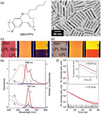 |
| | Fig. 3 (a) Chemical structure of MEH-PPV. (b) TEM image of the QRs. Photographs of (c) the LPLMEH-PPV film and (d) the LPLQR film obtained in visible light (left), in UV light (365 nm; middle), and in UV light (365 nm) through a linear polarizer placed parallel (‖) or perpendicular (⊥) to the direction of stretching (right). (e) Absorption (dotted lines) and PL (solid lines) spectra produced by the LPLMEH-PPV film (top) and the LPLQR film (bottom). The red and blue lines indicate parallel (‖) and perpendicular (⊥) LP light components against the stretching direction, respectively. The LPL films were excited with depolarized stationary light at 470 nm. (f) PL lifetime decay curve of the LPLMEH-PPV film (top) and the LPLQR film (bottom). The red dots, red lines, and grey line indicate the recorded data, the fitting curve, and the instrumental response function (IRF), respectively. The LPL films were excited with pulsed light at 470 nm. | |
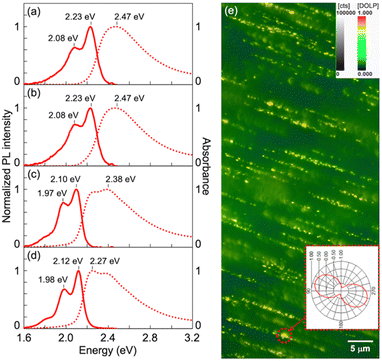 |
| | Fig. 4 Absorption (dotted lines) and PL (solid lines) spectra of (a) an MEH-PPV/toluene solution, (b) an MEH-PPV/EVA/toluene solution, (c) an MEH-PPV/EVA composite film, and (d) an LPLMEH-PPV film. (e) Degree of linear polarization (DOLP) image of an LPLMEH-PPV/EVA composite film obtained by QROM methodology (Section S1.8 in the ESI†).10 MEH-PPV/EVA ratio = 2.5 × 10⁻⁷ in mass, λexcitation = 490 nm, Iexcitation = 765 μW, λdetection > 520 nm. Inset polar plot describes the angular dependence of linear polarization corresponding to the bright area in the red dotted circle. | |
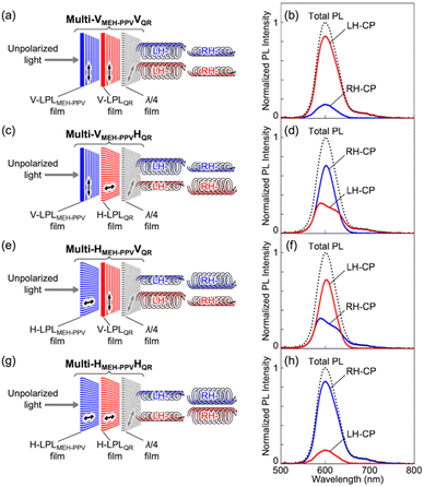 |
| | Fig. 5 Schematic illustration of (a) Multi-VMEH-PPVVQR, (c) Multi-VMEH-PPVHQR, (e) Multi-HMEH-PPVVQR, and (g) Multi-HMEH-PPVHQR. PL spectra of (b) Multi-VMEH-PPVVQR, (d) Multi-VMEH-PPVHQR, (f) Multi-HMEH-PPVVQR, and (h) Multi-HMEH-PPVHQR excited by depolarized light at 470 nm. The red and blue lines indicate LH- and RH-CP light components, respectively. The black dotted lines indicate total PL intensity. The total PL values were normalized so that the highest peak equalled one. | |
Because each of the four types of multi-layered luminescence-based CP convertors (Multi-VMEH-PPVVQR, Multi-VMEH-PPVHQR, Multi-HMEH-PPVVQR, and Multi-HMEH-PPVHQR) comprised two LPL films with different PL lifetimes, the generated CP light was considered to include temporal information. We obtained time-resolved spectral measurements using a fluorescence lifetime spectrometer operated with a CP light detection setup to evaluate the time-multiplexing of the chiroptical information generated by each convertor (see ESI†). As shown in Fig. 6, the PL spectral profiles of both the LH- and RH-CP components changed markedly over time. The time-course changes of the LH-CP component from Multi-VMEH-PPVVQR exhibited rapid attenuation of the double peak (590 nm and 620–630 nm), and slow attenuation of the single peak (610 nm) (Fig. 6a, left). The former and the latter signals can be attributed to emissions from MEH-PPV and QR, respectively. A similar result was observed for the RH-CP component from Multi-HMEH-PPVHQR (Fig. 6d, right). In the case of Multi-VMEH-PPVHQR (or Multi-HMEH-PPVVQR), the emission exhibited two different attenuation behaviors clearly separated into two CP light components with opposite handedness (Fig. 6b and c). Fig. 7a shows the spectral profiles of the total PL, LH-CP, and RH-CP components in the first 10 ns. All the initial spectral patterns of the total PL from the four convertors changed markedly within 10 ns and exhibited a peak shift from 590 to 610 nm (black empty circles and dotted lines in Fig. 7a). The changes in the LH- and RH-CP light profiles of Multi-VMEH-PPVVQR and Multi-HMEH-PPVHQR were similar to that of the total PL. However, the main components in the light generated by Multi-VMEH-PPVHQR and Multi-HMEH-PPVVQR switched within 3 ns, as shown in Fig. 7b. These results indicate that it is possible to generate time-multiplexed chiroptical information from the multilayer-type luminescence-based CP convertor by simply selecting the appropriate LPL films and azimuthal θluminogen angles.
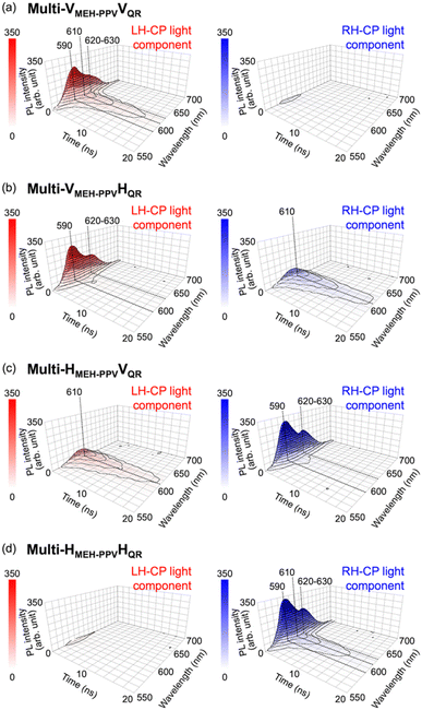 |
| | Fig. 6 Time-course changes in LH- (left) and RH- (right) CP light generated by (a) Multi-VMEH-PPVVQR, (b) Multi-VMEH-PPVHQR, (c) Multi-HMEH-PPVVQR, and (d) Multi-HMEH-PPVHQR. Red and blue indicate the light intensities of the LH- and RH-CP components, respectively. Each convertor was excited by depolarized pulsed light at 470 nm. | |
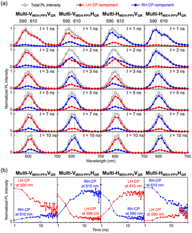 |
| | Fig. 7 (a) Time-course changes in PL spectra of Multi-VMEH-PPVVQR, Multi-VMEH-PPVHQR, Multi-HMEH-PPVVQR, and Multi-VMEH-PPVHQR. The total PL values were normalized so that the highest peak equalled one. The red and blue lines indicate LH- and RH-CP components, respectively. The black dotted lines indicate the total PL. Each convertor was excited by depolarized pulsed light at 470 nm. (b) Time-course changes in PL intensity of LH-CP components at 590 nm (blue lines in the two graphs on the left) and RH-CP components at 610 nm (red lines in the two graphs on the left) produced by Multi-VMEH-PPVVQR and Multi-VMEH-PPVHQR. Time-course changes in PL intensity of LH-CP components at 610 nm (red lines in the two graphs on the right) and RH-CP components at 590 nm (blue lines in the two graphs on the right) produced by Multi-HMEH-PPVVQR and Multi-HMEH-PPVHQR. | |
Conclusions
Herein, we reported the first example of time-multiplexing chiroptical information using a multilayer-type luminescence-based circular polarization convertor comprising two LPL films with different PL spectral profiles and different PL lifetimes. We fabricated LPL films with short and long PL lifetimes by uniaxial stretching MEH-PPV/EVA and QR/EVA composite films, respectively. The large polarization degree of the LPL (PLP-lum = 0.88) was attributable to the LPLMEH-PPV film, which contained bundle-shaped highly emissive domains. Using both LPLMEH-PPV and LPLQR films, we fabricated four different multilayer-type luminescence-based CP convertors by selecting the azimuthal angles between the polarization axes of the LPL films and the fast axes of the quarter-wave films. The prepared CP convertors generated four different types of steady-state chiroptical information. Time-varying of CP light spectral profiles were successfully produced by the four CP convertors and was extracted as time-multiplexed chiroptical information by time-resolved spectroscopy with CP detection. These findings will enable the design of novel CP light-generating materials for various fields, including time-multiplexed anti-counterfeit printing and optical data storage systems.
Author contributions
Y. Okazaki designed the project, raised funds, and wrote the original draft. M. Kimura prepared the LPLQR film. K. Nakamura prepared the LPLMEH-PPV film. H. Shimizu prepared all the multi-layered luminescence-based CP convertors. All the experimental measurements, observations, and analyses were carried out by Y. Okazaki and H. Shimizu, who made equal contributions. The fluorescence polarization microscopy study was carried out by G. Raffy and A. Del Guerzo. The time-resolved spectral measurements were supported by K. Yoshida and M. Takafuji. All the authors discussed the results and contributed to the interpretation of the data.
Conflicts of interest
There are no conflicts to declare.
Acknowledgements
This work was supported by JSPS KAKENHI (grant numbers 23K13620, 22KK0070, and 20KK0122), and the Adaptable and Seamless Technology Transfer Program through Target-driven R&D (A-STEP) from the Japan Science and Technology Agency (JST) (grant number JPMJTR22TB). H. Shimizu acknowledges a Grant for Overseas Research by the Division of Graduate Studies (DoGS) of Kyoto University.
Notes and references
-
(a) S. Lin, Y. Tang, W. Kang, H. K. Bisoyi, J. Guo and Q. Li, Nat. Commun., 2023, 14, 3005 CrossRef CAS PubMed
 ;
(b) X. Yu, D. Zhang, M. Xu, G. Song and Y. Xu, J. Mater. Chem. C, 2023, 11, 1684–1689 RSC
  ;
(c) Y. Shi, J. Han, X. Jin, W. Miao, Y. Zhang and P. Duan, Adv. Sci., 2020, 9, 2201565 CrossRef PubMed
  ;
(d) M. Kim, H. Lee, R. T. Snipes, M. J. Han and V. V. Tsukruk, Small, 2022, 18, 2104340 CrossRef CAS PubMed
  ;
(e) H. Li, H. Li, W. Wang, Y. Tao, S. Wang, Q. Yang, Y. Jiang, C. Zheng, W. Huang and R. Chen, Angew. Chem., Int. Ed., 2020, 59, 4756–4762 CrossRef CAS PubMed
  ;
(f) S. Ito, K. Ikeda, S. Nakanishi, Y. Imai and M. Asami, Chem. Commun., 2017, 53, 6323–6326 RSC
  .
.
-
(a) E. M. Sánchez-Carnerero, A. R. Agarrabeitia, F. Moreno, B. L. Maroto, G. Muller, M. J. Ortiz and S. de la Moya, Chem. – Eur. J., 2015, 21, 13488–13500 CrossRef PubMed
 ;
(b) J. Kumar, T. Nakashima and T. Kawai, J. Phys. Chem. Lett., 2015, 6, 3445–3452 CrossRef CAS PubMed
  ;
(c) Y. Sang, J. Han, T. Zhao, P. Duan and M. Liu, Adv. Mater., 2020, 32, 1900110 CrossRef CAS PubMed
  ;
(d) G. Albano, G. Pescitelli and L. Di Bari, Chem. Rev., 2020, 120, 10145–10243 CrossRef CAS PubMed
  ;
(e) S. Jiang and N. A. Kotov, Adv. Mater., 2022, 2108431 Search PubMed
  .
.
-
(a) J. Ferguson and E. R. Krausz, Chem. Phys. Lett., 1982, 93, 21–25 CrossRef CAS
 ;
(b) D. H. Metcalf, S. W. Snyder, S. Wu, G. L. Hilmes, J. P. Riehl, J. N. Demas and F. S. Richardson, J. Am. Chem. Soc., 1989, 111, 3082–3083 CrossRef CAS
  ;
(c) D. H. Metcalf, S. W. Snyder, J. N. Demas and F. S. Richardson, J. Am. Chem. Soc., 1990, 112, 469–479 CrossRef CAS
  ;
(d) M. F. Reid, J. Lumin., 1990, 45, 384–386 CrossRef CAS
  ;
(e) D. H. Metcalf, S. W. Snyder, J. N. Demas and F. S. Richardson, J. Phys. Chem., 1990, 94, 7143–7153 CrossRef CAS
  ;
(f) P. M. L. Block, P. Schakel and H. P. J. M. Dekkers, Meas. Sci. Technol., 1990, 1, 126–130 CrossRef
  ;
(g) L. Geng and L. B. McGown, Anal. Chem., 1992, 64, 68–74 CrossRef CAS
  ;
(h) J. A. Schauerte, D. G. Steel and A. Gafni, Proc. Natl. Acad. Sci. U. S. A., 1992, 89, 10154–10158 CrossRef CAS PubMed
  .
.
-
(a) D. F. De Rosa, P. Stachelek, D. J. Black and R. Pal, Nat. Commun., 2023, 14, 1537 CrossRef CAS PubMed
 ;
(b) B. Baguenard, A. Bensalah-Ledoux, L. Guy, F. Riobé, O. Maury and S. Guy, Nat. Commun., 2023, 14, 1065 CrossRef CAS PubMed
  ;
(c) U. Hananel, G. Schwaartz, G. Paiss, L. Arrico, F. Zinna, L. Di Bari, O. Cheshnovsky and G. Markovich, Chirality, 2021, 33, 124–133 CrossRef CAS PubMed
  ;
(d) L. E. MacKenzie, L.-O. Pålsson, D. Parker, A. Beeby and R. Pal, Nat. Commun., 2020, 11, 1676 CrossRef CAS PubMed
  ;
(e) S. A. Bourelle, R. Shivanna, F. V. A. Camargo, S. Ghosh, A. J. Gillett, S. P. Senanayak, S. Feldmann, L. Eyre, A. Ashoka, T. W. J. van de Goor, H. Abolins, T. Winkler, G. Cerullo, R. H. Friend and F. Deshler, Nano Lett., 2020, 20, 5678–5685 CrossRef CAS PubMed
  ;
(f) A. T. Frawley, R. Pal and D. Parker, Chem. Commun., 2016, 52, 13349–13352 RSC
  .
.
- Y. Okazaki, M. Kimura, K. Hachiya and T. Sagawa, J. Mater. Chem. C, 2023, 11, 935–942 RSC
 .
.
-
(a) P. M. L. Block and H. P. J. M. Dekkers, Chem. Phys. Lett., 1989, 161, 188–194 CrossRef
 ;
(b) Y. Nagata and T. Mori, Front. Chem., 2020, 8, 448 CrossRef CAS PubMed
  ;
(c) L. Arrico, L. Di Bari and F. Zinna, Chem. – Eur. J., 2021, 27, 2920–2934 CrossRef CAS PubMed
  .
.
-
(a) L. Carbone, C. Nobile, M. De Giorgi, F. D. Sala, G. Morello, P. Pompa, M. Hytch, E. Snoeck, A. Fiore, I. R. Franchini, M. Nadasan, A. F. Silvestre, L. Chiodo, S. Kudera, R. Cingolani, R. Krahne and L. Manna, Nano Lett., 2007, 7, 2942–2950 CrossRef CAS PubMed
 ;
(b) J. Dehnel, Y. Barak, I. Meir, A. K. Budniak, A. P. Nagvenkar, D. R. Gamelin and E. Lifshitz, ACS Nano, 2020, 14, 13478–13490 CrossRef CAS PubMed
  .
.
- G. Albano, G. Pescitelli and L. Di Bari, ChemNanoMat, 2022, 8, e202200219 CrossRef CAS
 .
.
-
(a) A. Köhler, S. T. Hoffmann and H. Bässler, J. Am. Chem. Soc., 2012, 134, 11594–11601 CrossRef PubMed
 ;
(b) F. C. Spano and C. Silva, Annu. Rev. Phys. Chem., 2014, 65, 477–500 CrossRef CAS PubMed
  .
.
- A. Chakrabarty, G. Raffy, M. Maity, L. Gartzia-Rivero, S. Marre, C. Aymonier, U. Maitra and A. Del Guerzo, Small, 2018, 14, 1802311 CrossRef PubMed
 .
.
|
| This journal is © The Royal Society of Chemistry 2024 |
Click here to see how this site uses Cookies. View our privacy policy here.  Open Access Article
 *a,
Hayaki
Shimizu
a,
Kaito
Nakamura
a,
Kyohei
Yoshida
 b,
Guillaume
Raffy
 c,
Misaki
Kimura
a,
Keita
Tsukamoto
a,
Rei
Akasegawa
a,
Kan
Hachiya
 a,
Makoto
Takafuji
 d,
André
Del Guerzo
 c and
Takashi
Sagawa
 *a
*a


; (b) X. Yu, D. Zhang, M. Xu, G. Song and Y. Xu, J. Mater. Chem. C, 2023, 11, 1684–1689 RSC
; (c) Y. Shi, J. Han, X. Jin, W. Miao, Y. Zhang and P. Duan, Adv. Sci., 2020, 9, 2201565 CrossRef PubMed
; (d) M. Kim, H. Lee, R. T. Snipes, M. J. Han and V. V. Tsukruk, Small, 2022, 18, 2104340 CrossRef CAS PubMed
; (e) H. Li, H. Li, W. Wang, Y. Tao, S. Wang, Q. Yang, Y. Jiang, C. Zheng, W. Huang and R. Chen, Angew. Chem., Int. Ed., 2020, 59, 4756–4762 CrossRef CAS PubMed
; (f) S. Ito, K. Ikeda, S. Nakanishi, Y. Imai and M. Asami, Chem. Commun., 2017, 53, 6323–6326 RSC
.
; (b) J. Kumar, T. Nakashima and T. Kawai, J. Phys. Chem. Lett., 2015, 6, 3445–3452 CrossRef CAS PubMed
; (c) Y. Sang, J. Han, T. Zhao, P. Duan and M. Liu, Adv. Mater., 2020, 32, 1900110 CrossRef CAS PubMed
; (d) G. Albano, G. Pescitelli and L. Di Bari, Chem. Rev., 2020, 120, 10145–10243 CrossRef CAS PubMed
; (e) S. Jiang and N. A. Kotov, Adv. Mater., 2022, 2108431 Search PubMed
.
; (b) D. H. Metcalf, S. W. Snyder, S. Wu, G. L. Hilmes, J. P. Riehl, J. N. Demas and F. S. Richardson, J. Am. Chem. Soc., 1989, 111, 3082–3083 CrossRef CAS
; (c) D. H. Metcalf, S. W. Snyder, J. N. Demas and F. S. Richardson, J. Am. Chem. Soc., 1990, 112, 469–479 CrossRef CAS
; (d) M. F. Reid, J. Lumin., 1990, 45, 384–386 CrossRef CAS
; (e) D. H. Metcalf, S. W. Snyder, J. N. Demas and F. S. Richardson, J. Phys. Chem., 1990, 94, 7143–7153 CrossRef CAS
; (f) P. M. L. Block, P. Schakel and H. P. J. M. Dekkers, Meas. Sci. Technol., 1990, 1, 126–130 CrossRef
; (g) L. Geng and L. B. McGown, Anal. Chem., 1992, 64, 68–74 CrossRef CAS
; (h) J. A. Schauerte, D. G. Steel and A. Gafni, Proc. Natl. Acad. Sci. U. S. A., 1992, 89, 10154–10158 CrossRef CAS PubMed
.
; (b) B. Baguenard, A. Bensalah-Ledoux, L. Guy, F. Riobé, O. Maury and S. Guy, Nat. Commun., 2023, 14, 1065 CrossRef CAS PubMed
; (c) U. Hananel, G. Schwaartz, G. Paiss, L. Arrico, F. Zinna, L. Di Bari, O. Cheshnovsky and G. Markovich, Chirality, 2021, 33, 124–133 CrossRef CAS PubMed
; (d) L. E. MacKenzie, L.-O. Pålsson, D. Parker, A. Beeby and R. Pal, Nat. Commun., 2020, 11, 1676 CrossRef CAS PubMed
; (e) S. A. Bourelle, R. Shivanna, F. V. A. Camargo, S. Ghosh, A. J. Gillett, S. P. Senanayak, S. Feldmann, L. Eyre, A. Ashoka, T. W. J. van de Goor, H. Abolins, T. Winkler, G. Cerullo, R. H. Friend and F. Deshler, Nano Lett., 2020, 20, 5678–5685 CrossRef CAS PubMed
; (f) A. T. Frawley, R. Pal and D. Parker, Chem. Commun., 2016, 52, 13349–13352 RSC
.
.
; (b) Y. Nagata and T. Mori, Front. Chem., 2020, 8, 448 CrossRef CAS PubMed
; (c) L. Arrico, L. Di Bari and F. Zinna, Chem. – Eur. J., 2021, 27, 2920–2934 CrossRef CAS PubMed
.
; (b) J. Dehnel, Y. Barak, I. Meir, A. K. Budniak, A. P. Nagvenkar, D. R. Gamelin and E. Lifshitz, ACS Nano, 2020, 14, 13478–13490 CrossRef CAS PubMed
.
.
; (b) F. C. Spano and C. Silva, Annu. Rev. Phys. Chem., 2014, 65, 477–500 CrossRef CAS PubMed
.
.


