 Open Access Article
Dilute nanocomposites for capacitive energy storage: progress, challenges and prospects
Li
Li
 a,
Wenhan
Xu
 a,
Guanchun
Rui
b,
Shixian
Zhang
 a,
Q. M.
Zhang
c and
Qing
Wang
 *a
*a
aDepartment of Materials Science and Engineering, The Pennsylvania State University, University Park, PA 16802, USA. E-mail: wang@matse.psu.edu
bArkema Inc., 900 First Avenue, King of Prussia, PA 19406, USA
cSchool of Electrical Engineering and Computer Science, Materials Research Institute, The Pennsylvania State University, University Park, PA 16802, USA
First published on 6th November 2024
Abstract
Electrostatic capacitors (ECs) are critical components in advanced electronics and electric power systems due to their rapid charge–discharge rate and high power density. While polymers are ideal for ECs due to their high voltage tolerance and mechanical flexibility, their low dielectric constants (K) and limited energy density remain significant limitations. Traditional polymer nanocomposites, which incorporate high-K ceramic fillers, have shown promise in enhancing dielectric properties but often at the cost of electric breakdown strength and scalability. In this perspective, we explore a pioneering approach that utilizes ultralow loadings of small-sized inorganic nanofillers to significantly improve dielectric constants without compromising other key properties. We delve into the unconventional effects observed in these polymer nanocomposites, including dielectric enhancements, charge trapping, mechanical reinforcements, and microstructural changes, and highlight the impressive energy storage performance achieved with minimal filler contents. We discuss innovative design strategies from viewpoints of polymer and filler structures and showcase recent advancements in nanoscale characterization and theoretical modelling for understanding the crucial role of polymer–filler interfaces. Finally, we stress fundamental challenges and prospects, providing insights into the transformative potential of these nanocomposites for next-generation energy storage applications.
1. Introduction
Electrostatic capacitors (ECs), offering a fast charge–discharge rate (in microseconds) and a high power density among mainstream energy storage technologies (e.g., up to 107–108 W kg−1 for ECs versus 10–102 and 102–106 W kg−1 for batteries and electrochemical capacitors, respectively), are indispensable in advanced electronics and electric systems such as electrified transportation, power conditioning and switching, and advanced propulsion.1–7 Dielectric materials, sandwiched between two electrodes, are the key components of ECs that store and release electric energy physically and are generally divided into two categories: ceramics and polymers. Comparatively, polymers are more preferred over ceramics in various applications such as high-voltage transmissions, electric vehicles, and electromagnetic launching because of their high voltage tolerance, flexibility, light weight, graceful failure mechanism, etc.8,9 However, despite their high electric breakdown strength (Eb) and efficiency (η), current polymer dielectrics show limited energy density due to their low dielectric constants (K < 10) and are significantly outperformed by ceramics such as BaTiO3 with a K over 1000.10,11 The state-of-the-art dielectric polymer, biaxially oriented polypropene (BOPP), with a K of 2.2 only delivers an energy density of 2–5 J cm−3, which is at least one order of magnitude lower than those of batteries. Consequently, these polymer-based capacitors can constitute up to 60% of the converter weight and 50% of the volume in high voltage direct current transmission systems and electromagnetic equipment.3,12,13 Furthermore, the operating temperatures of commercially available polymers for capacitors, such as BOPP, poly(ethylene naphthalate) (PEN), poly(ethylene terephthalate) (PET), and polycarbonate (PC), are inadequate for harsh-environment applications with high working temperatures, such as insulated gate bipolar transistors (IGBTs at 150 °C) and underground oil/gas exploration (170–250 °C).5 Under these conditions, the electrical conduction of dielectric polymers increases exponentially, drastically reducing Eb and η, thereby lowering Ue and leading to severe thermal runaway that threatens the functionality and lifespan of electric systems. Therefore, enhancing the energy storage performance of dielectric polymers at both room and high temperatures is crucial to meet the growing demands for miniaturization, light weight, and integration of electronic devices and electrical systems.The energy density of a dielectric polymer is fundamentally governed by the equation U = ∫EdD, where U, E and D represent the stored energy density, the electric field, and the electric displacement, respectively. For linear dielectric polymers, this is simplified as U = ½DE = ½Kε0E2, where D equals Kε0E and ε0 represents the vacuum permittivity (8.85 × 10⁻¹² F m−1).13 The efficiency is given by η = Ue/U × 100%. Therefore, improving the discharged energy density requires simultaneously increasing K and Eb while reducing energy loss. Early studies, guided by the mixing rule of combining the advantages of ceramics and polymers, explored incorporating high-K ceramic nanofillers into polymer matrices to form polymer nanocomposites.14–20 Although this method elevated K, it achieved limited success in enhancing Ue due to trade-offs between parameters, such as the mutually exclusive relationship between K and Eb [Eb–(1/K)1/2].21 The large discrepancy in K of polymers (<10 in most cases) and ceramics (up to hundreds and thousands) leads to highly inhomogeneous distributions of local electric fields and morphological imperfections such as voids at polymer–filler interfaces. Consequently, increasing K often results in much lower Eb and increased energy loss in polymer nanocomposites. In addition to the significantly compromised electric breakdown strength, the addition of high-K inorganic nanoparticles in a low-K polymer matrix usually increases the dielectric loss and leakage current in the resultant nanocomposites due to the inferior interfacial compatibility, which have been extensively reported.22 Moreover, other effects such as abnormal ferroelectricity-like properties may be induced in nanocomposites as the high-K filler content is over 20%, which further increases losses and decreases the charge–discharge efficiency.23 Recently, various strategies have been developed to address the dilemma, including modifications of nanofillers,24–28 gradient-structured interfacial design,29–31 and multi-layered nanocomposites.32–35 These efforts have simultaneously improved K and Eb, leading to unprecedentedly high Ue in dielectric polymers. Despite these advances, critical challenges remain. For example, enhancing the dielectric and capacitive performance of polymers often relies on using high-K fillers with relatively high loadings (usually 5–20 vol%) and large sizes (e.g., 100 nm in diameter), which compromise the mechanical and processing advantages of polymers, making large-scale fabrication through roll-to-roll processes difficult. Additionally, current high Ue values of polymer nanocomposites are often achieved under very high electric fields (e.g., >700 MV m−1) due to low K, raising reliability concerns for practical capacitor operation.
Intriguingly, a novel and straightforward polymer nanocomposite approach has emerged, featuring the addition of small amounts (<1 vol%) of inorganic nanofillers with small sizes (<50 nm) whose dielectric constant is similar to that of the polymer, which leads to significantly improved dielectric constants in nanocomposites without compromising electric breakdown and efficiency.36–41 For example, poly(ether imide) (PEI) nanocomposites with 0.3 vol% Al2O3 nanoparticles exhibit an increase in the dielectric constant from 3.2 of PEI to around 5.0 while maintaining low loss.36 This dilute nanocomposite approach overcomes many drawbacks associated with traditional nanocomposites that use high dielectric constant nanofillers at high volume fractions (>10 vol%). According to classic dielectric theory, dipolar (or orientational) polarization prominently determines the K of polymer materials with permanent dipoles.42 However, existing linear dipolar polymers exhibit low dipolar relaxation strength; for instance, PEI shows a relaxation strength of ≈0.3.41 Therefore, the enhanced dielectric responses in polymers with introduced nanofillers are unconventional and not fully understood within the existing dielectric framework. Besides, these emerging polymer nanocomposites demonstrate efficient charge trapping and substantial mechanical improvements, indicating high potential for achieving superior capacitive performance across varied temperatures. These remarkable effects have been observed in a diverse range of polymer nanocomposites comprising different polymers (both linear dielectric and ferroelectric polymers) and fillers [oxides, perovskites, quantum dots (QDs), etc.] of various sizes (from sub-nanometers to dozens of nanometers) and dimensions (0D nanoparticles, 1D nanowires, and 2D nanosheets).24,37–41,43–49 Furthermore, incorporating low contents of nanofillers does not compromise the mechanical flexibility and processing capability of the polymer. This endows the nanocomposites with high scalability, making them promising for large-area film production, which is crucial for replacing current polymer dielectric capacitors. This type of polymer nanocomposite not only enhances the dielectric and capacitive properties of dielectric polymers while retaining their scalability, but also raises new fundamental questions and fosters progress in chemistry and applied physics.
In this perspective article, we focus on the emerging phenomena and fundamental understandings of dilute nanocomposites for achieving high capacitive properties, from the viewpoints of material chemistry and physics. We begin by describing the unconventional effects (including electric, mechanical, and microstructural changes) observed in dilute nanocomposites and discuss the significant progress achieved. We then explore the design strategies of polymer nanocomposites, analysing how variations in polymer and filler structures influence the dielectric and energy storage properties. Following this, we highlight advancements in understanding the crucial role of polymer–filler interfaces in polymer nanocomposites, based on nanoscale interfacial probing and theoretical modelling. In the last section, we provide concluding remarks, offering perspectives on fundamental challenges and application prospects for developing scalable high-energy-density dielectric polymers and capacitors based on these polymer nanocomposites.
2. Emerging phenomena in dilute nanocomposites
2.1 Dielectric enhancements
In 2017, Thakur et al. demonstrated that incorporating a very low volume of Al2O3 nanoparticles (∼0.3 vol%) into PEI could significantly enhance the dielectric constant to approximately 5, marking an increase of over 55% compared to pure PEI (Fig. 1a).36 This enhancement was achieved without altering the dielectric loss or Eb, resulting in improved energy storage capabilities (2.9 J cm−3 compared to 1.9 J cm−3 for pure PEI at 350 MV m−1). This significant increase in K is particularly noteworthy given the glassy state of PEI (glass transition temperature, Tg of 217 °C) and intrinsic weak dipolar responses and the low K of Al2O3 (≈10) and its small volume fraction. The observed high dielectric constant is limited to a narrow range of filler content (0–1 vol%), which cannot be explained by traditional dielectric models such as those by Wiener,50 Maxwell-Garnett,51–53 and Bruggeman54,55 that rely on simple volumetric summations of individual components' dielectric constants. Moreover, the PEI/Al2O3 nanocomposites exhibit high dielectric stability over a wide frequency (1–106 Hz) and temperature range (−50 to 250 °C). These dielectric behaviours distinctly differ from those of previously reported polymer nanocomposites with low filler contents (0.01–0.1 vol%) of conductive fillers (such as Ag, graphene, etc.) where high K is achieved through percolative or interfacial polarization mechanisms.53,54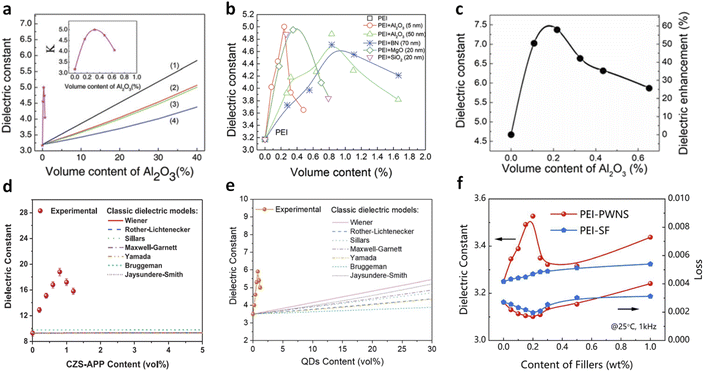 | ||
| Fig. 1 Dielectric constant of PEI nanocomposites as a function of (a) Al2O3 nanoparticle contents and (b) various filler contents. Lines (1–4) are the fitted plots of dielectric constants as a function of filler content with classic two-phase dielectric composite models: (1) parallel, (2) Maxwell, (3) Lichtenecker, and (4) series models. Figures (a) and (b) have been reproduced from ref. 36 with permission from The Royal Society of Chemistry, copyright 2017. (c) Dielectric constant of PEEU nanocomposites as a function of Al2O3 nanoparticle contents. This figure has been reproduced from ref. 37 with permission from the American Association for the Advancement of Science, copyright 2020. (d) Dielectric constant of P(VDF-HFP) nanocomposites as a function of CZS-APP QDs (Cd1−xZnxSe1−ySy quantum dots modified with 3-amino-1-propanol ligand) contents. This figure has been reproduced from ref. 38 with permission from John Wiley and Sons, copyright 2021. (e) Dielectric constant of poly(methyl methacrylate)(PMMA) nanocomposites as a function of QD contents. This figure has been reproduced from ref. 39 with permission from The Royal Society of Chemistry, copyright 2021. (f) Dielectric constant of PEI nanocomposites as a function of phosphotungstic acid subnanosheets (PWNSs) and oleylamine (SF) contents. This figure has been reproduced from ref. 24 with permission from Springer Nature, copyright 2024. | ||
Up to present, various dilute nanocomposites have been explored, including polymers such as PEI, polyimide (PI), poly(arylene ether urea) (PEEU), poly(ether methyl ether urea) (PEMEU), and polyaryletherketone (PAEK), and fillers such as boron nitride nanosheets (BNNSs), MgO nanoparticles, and SiO2 nanoparticles (Fig. 1b).36,37 These nanocomposites address the fundamental K–Eb trade-off, achieving high capacitive energy storage performance. Zhang et al. reported a significant enhancement in the dielectric constant from 4.7 (pristine PEEU) to 7.4 in a PEEU nanocomposite with 0.3 vol% Al2O3 nanoparticles (Fig. 1c).37 These nanocomposites maintain a comparable loss to PEEU (∼0.01 at 1 kHz) and a high breakdown strength of ∼900 MV m−1 (50% higher than that of PEEU), resulting in a high Ue of ≈27 J cm−3 at room temperature. We reported a significant increase in the dielectric constant (from 9.3 to 18.6) in ferroelectric polymer, poly(vinylidene fluoride-co-hexafluoropropylene) [P(VDF-HFP)], with the addition of <1 vol% CZS-APP QDs (Fig. 1d).38 A further improvement of K from 3.5 of PMMA to 5.9 was observed in a nanocomposite with 0.8 vol% QDs, while maintaining the same dielectric loss as that in neat PMMA (Fig. 1e).39 More recently, Yang et al. reported an enhanced dielectric constant of 3.5 in PEI nanocomposites with 0.2 wt% PWNSs compared to 3.2 for pure PEI, along with substantial improvements in breakdown strength at high temperatures, e.g., 694 MV m−1, 48% higher than that of PEI (466 MV m−1) at 150 °C (Fig. 1f).24,56 These studies demonstrate the potential for achieving high K and high capacitive energy storage performance at both room and high temperatures in dilute nanocomposites.
Continuous research in this area has dramatically improved the dielectric constants of dipolar linear dielectric polymers. The enhancement ratios of K have increased from ∼55% in PEI/Al2O3 to ∼69% in PMMA/QDs and ∼150% in PI/MgO nanocomposites,36,39,45 resulting in an impressively high K around 7.5, which is even comparable to that of ferroelectric polymers such as poly(vinylidene fluoride) (PVDF, K of 7–12). However, the underlying mechanisms for these substantial enhancements remain not fully understood. It is generally believed that the induced local free space (or free volume) by the nanofillers reduces constraints on dipole motions, which are otherwise restricted by the glassy state of high-Tg polymers. Current studies suggest that the dielectric enhancement effect is related to the polar structures of the dielectric polymers and can be tuned by varying the sizes, dimensions, and surface environments of the fillers, which will be further discussed in Section 3.
2.2 Charge trapping
Charge trapping by nanoparticles such as Al2O3, BNNS, etc., in polymers has been widely reported,1,57–59 which primarily originates from their wide bandgap structures and surface ligands with high electron affinity, leading to inhibited long-range carrier transport and thus lowered electrical conduction. As a result, these polymer nanocomposites exhibit improved Eb and η, even at high temperatures. Previously, achieving significant charge trapping requires high filler content (>5 vol%), which may compromise the mechanical flexibility of the polymer and is not ideal for scalable industrial production. Recent findings, however, show that even very low amounts of nanofillers (<1 vol%) with ultrasmall dimensions (at least in one dimension) can induce efficient charge trapping comparable to or even superior to that in traditional high-content nanocomposites.24,37,44–47,60 For example, it has been reported that due to the introduction of PWNSs that offer deep trap sites in the polymer, the maximum depolarization current density (correlating with trap density) of the nanocomposites with only 0.2 wt% filler contents reaches 1.86 × 10⁻¹⁰ A cm−2, observed from thermally stimulated depolarization current (TSDC) curves, which is nearly two orders of magnitude higher than that in PEI- or PI-based nanocomposites.24 As a result, the leakage current is significantly reduced in the nanocomposites (Fig. 2).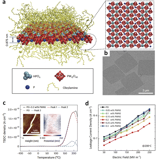 | ||
| Fig. 2 (a) Schematic illustration of PWNSs. (b) TEM image of PWNSs. (c) TSDC curves of PEI and PEI/PWNS nanocomposites. (d) Leakage current density of PEI and PEI/PWNS nanocomposites. This figure has been reproduced from ref. 24 with permission from Springer Nature, copyright 2024. | ||
The enhanced charge trapping at low filler contents is related to the chemical and electronic structural changes of the fillers with small sizes and low dimensions. The reduction in size increases the ratio of surface atoms, which include abundant under-coordinated atoms or hanging bonds that create surface defect states for charge trapping. Smaller fillers also increase the polymer–filler interfacial regions, providing numerous interfacial traps for carriers. Therefore, doping with ultrasmall nanofillers not only improves dipolar responses but also significantly enhances charge trapping capabilities, which is beneficial for high energy storage under high electric fields and elevated temperatures. Despite significant advancements, there are unresolved challenges in understanding the trapping mechanisms and developing nanocomposites that achieve both a high dielectric constant (K) and efficient carrier trapping. For instance, the literature suggests a correlation between trap density and dielectric constant with filler content, which are often attributed to the role of interfacial volume. However, recent studies have shown discrepancies. For instance, PMMA/Al2O3 nanocomposites demonstrate the highest dielectric constant at 0.2 vol% Al2O3, while the highest trapping density and breakdown strength are observed at a higher filler content of 1 vol%.44 Such inconsistency indicates that the electric charging is possibly governed by other processes in addition to the interfacial effects determining the dielectric behaviours, which highlight the need for further investigation into the mechanisms of deep trapping in nanocomposites with low filler contents.
2.3 Mechanical reinforcements
Aside from the electrical properties, the addition of small-sized nanofillers at ultralow contents in polymer nanocomposites has been found to significantly enhance mechanical properties, an effect that current mechanistic theories do not fully explain. The increase in mechanical strength (represented by Young's modulus, Y) is crucial for achieving a high Eb in dielectric polymers, according to the electromechanical model: Eb = (4πY/(Kε0))1/2.21 High mechanical properties also facilitate large-area film processing and practical applications, giving rise to high energy density and good scalability with low filler loadings. We observed a significant increase in Young's modulus for PMMA with a small amount of QDs, e.g., from 1.78 GPa of pristine PMMA to 2.58 GPa (approximately a 45% enhancement) of the nanocomposite with 0.8 vol% QDs (Fig. 3a).39 This increase in Y resulted in a highly improved Eb and energy density (Fig. 3b). This enhancement contradicts the classic two-phase average mixing rule, suggesting unique effects of nanofillers. Microscopic and theoretical studies attributed these effects to the uniform distribution of fillers and favorable polymer/filler interactions. Similarly, recent research by Yang et al. reported that a low loading (<0.5 wt%) of sub-nanosheets (PWNSs) could strengthen various dielectric polymers such as PEI, PI, and fluorinated PI (FPI), effectively hindering breakdown path propagation (Fig. 3c).24 The Young's modulus of PEI nanocomposite with only 0.2 wt% of PWNSs was higher than the average value of PEI and PWNSs, owing to effective stress transfer from the polymer to the nanosheets that possess large surface area-to-thickness ratios, revealed by finite element simulations. Phase-field simulations showed that breakdown paths followed the PWNS–polymer interface, resulting in longer and tortuous paths. Consequently, these nanocomposites exhibited high breakdown strength at high temperatures. For instance, an FPI-based nanocomposite with 0.2 wt% PWNSs achieved an ultrahigh Eb of ≈830 MV m−1 at 200 °C (Fig. 3d), significantly higher than that of pristine FPI (≈590 MV m−1), resulting in a high energy density of 7.2 J cm−3 with 90% charge–discharge efficiency at 200 °C.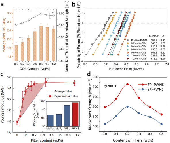 | ||
| Fig. 3 (a) Young's modulus and (b) Weibull breakdown plots of PMMA nanocomposites with various QD contents. Figures (a) and (b) have been reproduced from ref. 39 with permission from The Royal Society of Chemistry, copyright 2021. (c) Young's modulus of PEI/PWNS nanocomposites as a function of filler contents. (d) Breakdown strength of FPI/PWNS and sPI/PWNS nanocomposites as a function of filler contents. Figures (c) and (d) have been reproduced from ref. 24 with permission from Springer Nature, copyright 2024. | ||
Although the substantially increased mechanical properties are conducive to achieving high energy storage performance, the origins of mechanical enhancements at ultralow filler contents remain unclear. Traditional theories suggest that nanoparticles can enhance mechanical strength by promoting stress transfer from soft polymer phases to hard fillers, acting as crosslinking agents, aiding in crystallization, etc.19,61,62 However, these effects are usually observed at high filler loadings. Current reports suggest that the remarkable mechanical reinforcement observed at ultralow loadings likely results from a combination of multiple factors, including the nanofillers' ultrafine sizes, large specific surface areas, and favourable interactions with the polymer.3,38,63 Further experimental and theoretical investigations are needed to fully understand and confirm the underlying mechanisms.
2.4 Microstructural changes
The introduction of ultralow amounts of small-sized fillers into polymers can significantly alter their microstructures at the polymer–filler interfaces, which are regarded as the possible origins of the enhanced electrical and mechanical properties. These structural changes include expansion of local free volume, disruption of inter-chain interactions, and promotion of crystallization and phase transitions—effects that are less commonly observed in conventional polymer nanocomposites with high filler loadings.37,38,40,43,64 These findings challenge previous understanding, which suggested that fillers without proper chemical modifications primarily impact macroscopic properties such as electrical conductivity and mechanical flexibility, but generally have minimal effects on polymer microstructures due to their larger sizes and weak interactions between the organic matrix and inorganic fillers.Zhang et al. investigated the mean inter-chain distance using X-ray diffraction (XRD) and found that PEEU nanocomposites with 0.21 vol% nanofillers exhibited a 5.8% increase in chain spacing compared to both pure PEEU and nanocomposites with higher filler loadings (Fig. 4a).37 Infrared (IR) spectroscopy revealed that these nanofillers also softened hydrogen bonding in the polymer matrix, reducing constraints on the urea dipoles (Fig. 4b). This weakening of hydrogen bonding and expansion of inter-chain spacing create additional local free volume for dipoles, enhancing their response to external electric fields and increasing the dielectric constant. Changes in specific heat capacity (ΔCp) during the glass transition further reflect these local structural alterations. Chen et al. observed that in PEI nanocomposites with Al2O3 nanorods, ΔCp peaks at approximately 0.75 vol% loading, indicating that PEI backbones become more coiled compared to pristine PEI before the glass transition (Fig. 4c).41 This coiled conformation increases the average inter-chain spacing, consistent with the XRD results. Although Tg remains unchanged with nanorod loading, indicating no significant impact on long-range chain segmental motions, the enhanced local free volume facilitates better dipole alignment in response to applied electric fields. Atomic force microscopy-infrared spectroscopy (AFM-IR) studies further showed that the ether bonds—rotatable backbone groups of PEI—contribute to local chain distortions around the nanofillers in PEI nanocomposites (Fig. 4d–f).65,66
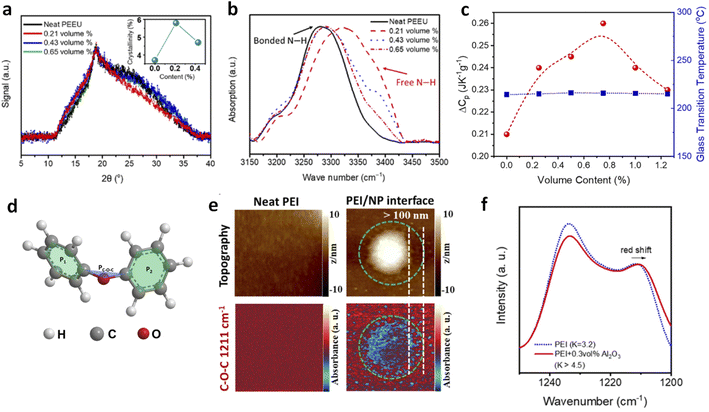 | ||
| Fig. 4 (a) XRD patterns and (b) FTIR spectra of PEEU/Al2O3 nanocomposites. Figures (a) and (b) have been reproduced from ref. 37 with permission from the American Association for the Advancement of Science, copyright 2020. (c) ΔCp and Tg of PEI nanocomposites as a function of Al2O3 contents. This figure has been reproduced from ref. 41 with permission from Elsevier, copyright 2020. (d) Schematic chemical structure of Ph–O–Ph (diphenyl ether) and the three planes determining the dihedral angles. (e) AFM-IR mapping of topography and IR response with selected wavenumbers for neat PEI and PEI nanocomposites with 300 nm diameter BaTiO3. (f) FTIR spectra of neat PEI and PEI dilute nanocomposites with 0.3 vol% 20 nm alumina nanoparticles. Figures (d)–(f) have been reproduced from ref. 65 with permission from the American Institute of Physics, copyright 2023. | ||
In crystalline polymers, the effects of low-loading nanofillers on microstructural changes can be more pronounced.38,64,67 For instance, Wang et al. reported that low-density polyethylene (LDPE)/Al2O3 nanocomposites with 0.12 vol% Al2O3 (30 nm diameter particles) increased LDPE crystallinity, enhancing breakdown field strength and reducing conduction losses at high electric fields compared to neat LDPE and composites with higher filler loadings.67 Similarly, in PEEU/Al2O3 nanocomposites with 20 nm particles, an increase in crystallinity and reduced crystallite size were observed at 0.21 vol% filler loading.37 This reduction in crystallite size is beneficial as it decreases the mean free path for mobile charges, resulting in lower conductivity and improved breakdown strength.
3. Designing dilute nanocomposites
The exceptional dielectric, mechanical, and charge trapping properties observed in polymer nanocomposites are intricately linked to the compositions and structures of both the polymers and fillers. The diverse combinations of these materials create a large family of polymer nanocomposites, offering numerous opportunities to fine-tune their properties and achieve outstanding capacitive energy storage performance across various temperatures. In this section, we discuss the effects of polymers and fillers of different structures on the dielectric and capacitive properties and explore design strategies for optimizing polymer nanocomposites.3.1 Polymers
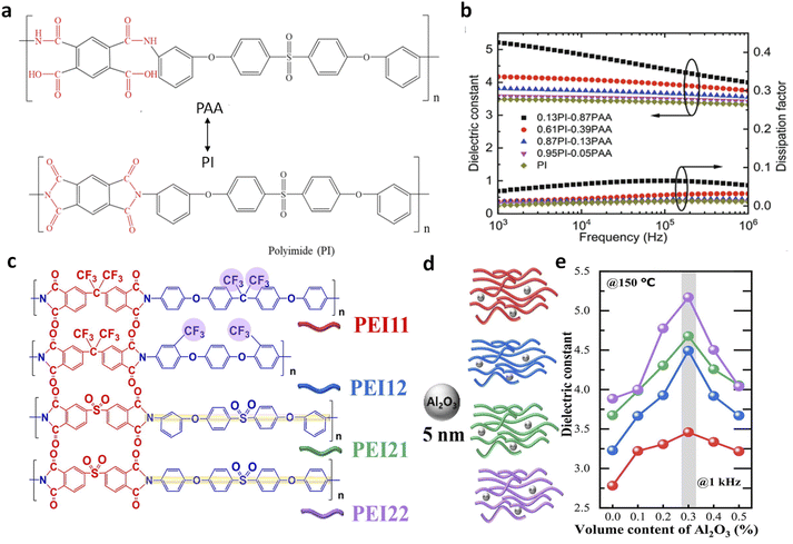 | ||
| Fig. 5 (a) Chemical structures of PAA and PI. (b) Frequency-dependent dielectric constant and loss spectra of PI-PAA copolymers with various molar ratios. Figures (a) and (b) have been reproduced from ref. 46 with permission from John Wiley and Sons, copyright 2021. (c) Chemical structures of various modified PEIs with –CF3 and –SO2 groups. (d) Schematic illustration of Al2O3 nanoparticles and the PEI/Al2O3 nanocomposites. (e) Dielectric constant as a function of Al2O3 contents of the four kinds of PEI nanocomposites with Al2O3 nanoparticles. Figures (c)–(e) have been reproduced from ref. 68 with permission from Elsevier, copyright 2020. | ||
We previously reported that incorporating ultralow ratios (<1 vol%) of low-K Cd1−xZnxSe1−ySy QDs into P(VDF-HFP) resulted in substantial increases in both K and Eb, thus high energy density (Fig. 6a and b).38 The K increased from 9.3 in P(VDF-HFP) to 18.6 in the nanocomposite with 0.8 vol% QDs, representing a 100% enhancement, while the dielectric loss remained nearly unchanged at 0.04. This is in contrast to traditional polymer nanocomposites with high-K fillers such as BaTiO3, TiO2, and SrTiO3, which typically show K values below 12 at similar loadings. The observed dielectric enhancements are attributed to local structural changes induced by the small-sized fillers, including improvements in crystallization (Fig. 6c), transitions from non-polar to polar phases (Fig. 6d), and induced interfacial dipoles. Additionally, the nanocomposites achieved a high Eb of 621 MV m−1, originating from enhanced mechanical strength and reduced leakage current at such low filler contents. More recently, Li et al. reported that PVDF/TiO2 nanocomposites with 0.35 vol% filler loadings exhibit a dielectric constant of 9.5, i.e., a ∼35% increase compared to pristine PVDF.43 This dielectric enhancement, similar to that observed in P(VDF-HFP)/QDs, demonstrates that small-sized nanofillers can induce significant conformational changes in ferroelectric polymers at ultralow filling ratios, enhancing dielectric responses and electric polarization without compromising breakdown strength and mechanical properties. This is attributed to the large volume fractions of interfacial regions surrounding the fillers, which facilitate the formation of polar conformations (Fig. 6e). The nonpolar-to-polar conformation transformation has been further confirmed by molecular simulations (Fig. 6f and g). Advanced microscopic probing techniques for local chemical characterization of interfaces have also been conducted, supporting the important role of interfaces in determining these properties, which will be discussed in Section 4.
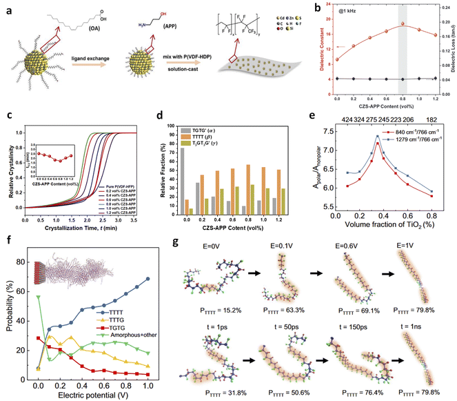 | ||
| Fig. 6 (a) Schematic illustration of fabrication of P(VDF-HFP)/QD nanocomposites. (b) Dielectric constant and loss, (c) relative crystallinity, and (d) relative fractions of phases of P(VDF-HFP) nanocomposites as a function of QD contents. Figures (a)–(d) have been reproduced from ref. 38 with permission from John Wiley and Sons, copyright 2021. (e) Polar/nonpolar ratios in PVDF nanocomposites as a function of TiO2 nanoparticle contents. (f) Probability of various chain conformations as a function of electric potential in PVDF/TiO2 nanocomposite models by molecular simulations. (g) Snapshots of chain conformations at different electric potentials and simulation times. Figures (e)–(g) have been reproduced from ref. 43 with permission from Springer Nature, copyright 2023. | ||
Besides conformational changes, low loadings of nanofillers also influence the orientation and alignment of polymer chains and dipoles in ferroelectric polymers. It has been reported that fillers with large specific surface areas, such as nanosheets, can cause significant enhancements in dielectric, capacitive energy storage, and piezo- and ferroelectric properties through “anchoring” effects.73–75 For instance, preferred orientations of all-trans conformations of poly(vinylidene fluoride-co-trifluoroethylene) [P(VDF-TrFE)] on the surface of 2D MXene materials were reported, leading to improved dielectric and piezoelectric constants (e.g., d33 is −52 pC N−1 for nanocomposites with 0.5 wt% MXene).73 Furthermore, a self-polarized phenomenon before electric poling has been observed due to surface “anchoring” effects. These findings highlight the potential of using low contents of nanofillers to fine-tune the structures and ferroelectric properties of polymers, with exciting possibilities for future exploration.
3.2 Tuning filler structures
Recent advances in dilute nanocomposites have proved that the intrinsic structures of nanofillers significantly influence the overall performance of these materials. However, a lack of clear guidelines for the selection and engineering of nanofillers has impeded further progress in achieving high performance at ultralow loadings. In this section, we summarize recent developments and explore key considerations for engineering nanofiller structures, including their size, dimensionality, and surface environment. By optimizing the electrical and chemical properties of nanofillers, it is possible to develop polymer nanocomposites with excellent scalability and superior energy storage capabilities at both room and high temperatures.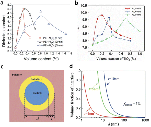 | ||
| Fig. 7 Dielectric constant of (a) PEI/Al2O3 and (b) PVDF/TiO2 nanocomposites with varied filler sizes. Figure (a) has been reproduced from ref. 36 with permission from The Royal Society of Chemistry, copyright 2017. Figure (b) has been reproduced from ref. 43 with permission from Springer Nature, copyright 2023. (c) Schematic diagram of a polymer–filler interface. (d) Theoretical volume fractions of the interface as a function of filler sizes at different interface thicknesses. Figures (c) and (d) have been reproduced from ref. 72 with permission from John Wiley and Sons, copyright 2018. | ||
However, smaller nanofillers do not always result in higher dipolar responses compared to larger fillers. Chen et al. found that PEI/nanorod composites with varying nanowire sizes (diameters of 35, 10, and 5 nm) showed different dielectric behaviours.41 PEI films with smaller nanowires (5 nm and 10 nm) exhibited dielectric enhancement peaks at around 0.2 vol% with K values of 4.1 and 4.6, respectively, which were lower than the K value of 6 observed in films with 35 nm nanorods. The authors attributed this discrepancy to the different effects of size on 1D fillers compared to nanoparticles. For nanowires, the bending or coiling against external forces is governed by flexural rigidity (Y × I), where I = ![[double bond, length as m-dash]](https://www.rsc.org/images/entities/char_e001.gif) R4π/4 is the second moment of area. The dependence of flexural rigidity on R4 means that 35 nm nanorods have significantly higher rigidity than 5 nm and 10 nm nanowires. As a result, smaller nanowires tend to coil, which impacts the formation of multilayer shell structures and results in lower dielectric enhancement.
R4π/4 is the second moment of area. The dependence of flexural rigidity on R4 means that 35 nm nanorods have significantly higher rigidity than 5 nm and 10 nm nanowires. As a result, smaller nanowires tend to coil, which impacts the formation of multilayer shell structures and results in lower dielectric enhancement.
Furthermore, smaller nanofillers tend to exhibit more pronounced charge trapping effects compared to larger fillers. For instance, the formation of oxide nanoclusters from small nanofillers can significantly enhance charge trapping, leading to lower conduction loss and higher breakdown strength.77 This is related to quantum size effects, where the bandgap decreases sharply as material sizes approach the characteristic Bohr radius,64,78 resulting in a higher conduction band minima (CBM) and/or lower valence band maxima (VBM), while deep trap levels remain unchanged. Consequently, electrical conductivity is reduced, leading to higher Eb and Ue values. However, it should be noted that quantum tunnelling effects may occur as filler size decreases, which in turn promote electron transport in the polymer thus leading to higher leakage current. Therefore, considerations of critical sizes are required when reducing filler sizes for achieving the best charge trapping effects in polymer nanocomposites.
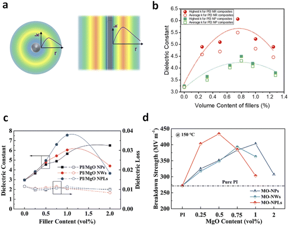 | ||
| Fig. 8 (a) Schematic distribution of the dielectric constant in the polymer–filler interface region as a function of the distance to 0D (nanoparticle) and 1D (nanorod) fillers. (b) Dielectric constant of PEI nanocomposites with nanorod and nanoparticle fillers as a function of filler contents. Figures (a) and (b) have been reproduced from ref. 41 with permission from Elsevier, copyright 2021. (c) Dielectric constant and (d) breakdown strength of PI nanocomposites with MgO NPs, NWs and NPLs at various filler contents. Figures (c) and (d) have been reproduced from ref. 45 with permission from John Wiley Sons, copyright 2022. | ||
Zhang and Chen et al. investigated the effects of modifying Al2O3 nanoparticles with an organic molecule that introduces alkyl groups, forming a ∼1 nm thick coating on the nanoparticle surface (Fig. 9a and b).40 They compared the dielectric properties of PEI nanocomposites modified with these nanoparticles to those with unmodified oxides. The results showed a decrease in the peak dielectric constant from 4.8 in the original PEI nanocomposites to 4.0 with the modified fillers (Fig. 9c). Similarly, in PEEU/Al2O3 nanocomposites, the dielectric constant decreased from 7.4 to 6.2 after filler modification. The shift of dielectric constant peaks to higher filler volume ratios indicated that the reduced propensity for hydrogen bond formation in the modified nanocomposites was partially offset by the increased total surface area of the nanoparticles. However, proper surface modifications can also increase dielectric responses. Li et al. modified QDs by first grafting short mercaptopropionic acid (MPA) ligands through a ligand exchange method, followed by bonding with a long perfluorosiloxane molecule, 1H,1H,2H,2H-perfluorooctyltriethoxysilane (POTS) (Fig. 9d).64 Following that, they introduced the modified QDs (denoted as QDs-M and QDs-M-P, respectively) into ferroelectric polymer P(VDF-HFP) and observed an increase in K from 8.5 for pure P(VDF-HFP) to 14.4 and 17.8 for nanocomposites with 0.82 vol% QDs-M and QDs-M-P, respectively (Fig. 9e). The higher dielectric enhancement observed with QDs modified with perfluorinated groups compared to those with MPA ligands highlights the effectiveness of surface modifications in tuning dielectric properties. Structural analyses revealed that QDs-M-P induced higher crystallinity (38.3% vs. 36.1%) and faster crystallization kinetics (1.7 min vs. 2.0 min) than QDs-M in the polymer, in addition to higher polar phase ratios, which contribute to higher dielectric responses.
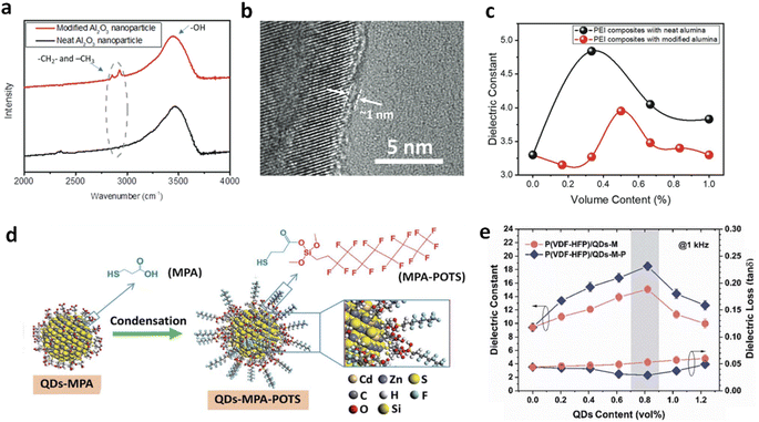 | ||
| Fig. 9 (a) FTIR spectra of neat Al2O3 and surface-modified Al2O3 with alkane groups. (b) TEM image of modified Al2O3. (c) Dielectric constant of PEI nanocomposites with neat Al2O3 and modified Al2O3 as a function of filler contents. Figures (a)–(c) have been reproduced from ref. 40 with permission from The Royal Society of Chemistry, copyright 2021. (d) Schematic illustration of surface modification of QDs. (e) Dielectric constant and loss of P(VDF-HFP) nanocomposites with QDs-MPA and QDs-M-P as a function of filler contents. Figures (d) and (e) have been reproduced from ref. 64 with permission from The Royal Society of Chemistry, copyright 2020. | ||
Surface modifications of fillers with organic ligands can also trap electrons and impede carrier transport, reducing conduction loss and thus enhancing Eb and Ue. Due to the higher bandgap (5.7 eV) and stronger electronegativity of the perfluorinated groups, the P(VDF-HFP)/QDs-M-P nanocomposites exhibited a suppressed dielectric loss of 0.029, compared to up to 0.061 for P(VDF-HFP)/QDs-M, leading to an improved Ue of 21.4 J cm−3 with high efficiencies of 90% and 78.3% at 300 and 531 MV m−1, respectively.64 Similarly, recent studies have shown that nanosheets modified with oleylamine ligands exhibit significant electron-capturing effects in PEI and FPI-based polymer nanocomposites, leading to improved Eb and efficiency at high temperatures (150 and 200 °C).24 Experimental and simulation studies reveal that these thin and large nanosheets, with abundant surface ligands, show not only high compatibility with the polymer, but also induce deep traps thus inhibiting charge transport in the polymer nanocomposites.
Additionally, modifying fillers with positively charged surfaces is another promising approach to enhance charge trapping and energy storage properties. For instance, calcium silicate colloidal nanoparticles (CSO) with positively charged surfaces were prepared using triethylamine (TEA) as a capping agent.80 The electrostatic repulsion from these positively charged nanoparticles leads to a good distribution throughout the polymer matrix. Moreover, these nanoparticles enhance resistivity by trapping electrons thus restricting carrier transport under high electric fields and at high temperatures. This results in excellent high-temperature energy storage properties of the PI/CSO composite (7.33 J cm−3 and 70% at 616 MV m−1 and 150 °C). These results highlight the effectiveness of various chemical modifications of fillers in optimizing both the dielectric properties and charge trapping capabilities of polymer nanocomposites, demonstrating the great potential of surface engineering of nanofillers in enhancing capacitive performance at varied temperatures.
4. Understanding interfaces by microscopic probing and modelling
Dilute nanocomposites have demonstrated remarkable dielectric, mechanical, and energy storage properties. These enhancements are attributable to microstructural changes—such as inter-chain distancing and conformational ordering—that differ significantly from those in conventional polymer nanocomposites. These structural changes are believed to originate at nanoparticle–polymer interfaces, where polymer chains adopt distinct configurations and exhibit different dipole activities compared to the bulk polymer. Theoretical models such as the electric double layer and multi-core models proposed by Lewis and Tanaka (Fig. 10a and b),42,82–84 respectively, describe the interfacial effects—including chain mobility, free volume, and carrier concentration—that occur within a thickness range up to hundreds of nanometers around the nanoparticle.43,81 These models are widely used to understand polymer nanocomposites with low filler loadings. However, despite the promise of tailoring properties through interfaces, the exact interfacial structures remain unclear. There is a lack of nanoscale evidence regarding the composition, structure, and polarity of these interfaces, which is crucial for understanding how polymer–filler interfaces influence the nanocomposites' structures and properties.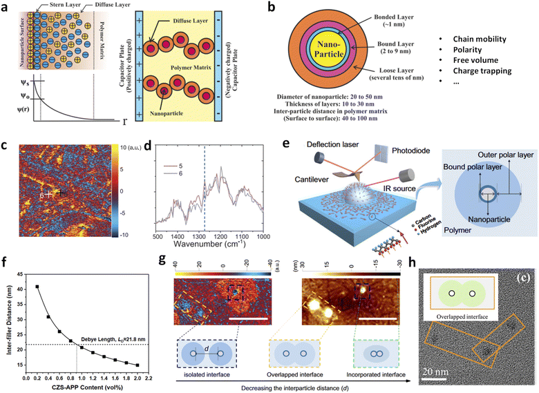 | ||
| Fig. 10 (a) Diffuse electric double-layer model, along with the resulting electrical potential distribution ψ(r) and conduction in a composite system. (b) Multi-core model of the polymer–nanoparticle interface. Figures (a) and (b) have been reproduced from ref. 42 with permission from the American Chemical Society, copyright 2016. (c) AFM-IR mapping and (d) local IR spectra of BTO/P(VDF-TrFE-CFE) with BTO of 100 nm in diameter. Figures (c) and (d) have been reproduced from ref. 81 with permission from John Wiley Sons, copyright 2020. (e) AFM-IR measurement and the reconstructed dipole orientations in the interfacial region (left), and the interface model consisting of two interfacial polymer layers (right). This figure has been reproduced from ref. 43 with permission from Springer Nature, copyright 2023. (f) Theoretical inter-filler distances as a function of CZS-APP contents in P(VDF-HFP) nanocomposites. This figure has been reproduced from ref. 38 with permission from John Wiley and Sons, copyright 2021. (g) AFM-IR chemical map with irradiation using a laser at 840 cm−1 (left) and the corresponding height image (right) of the PVDF/TiO2 nanocomposite with different inter-particle distances. This figure has been reproduced from ref. 43 with permission from Springer Nature, copyright 2023. (h) TEM image of a PMMA/Al2O3 nanocomposite film with overlapped interfaces. This figure has been reproduced from ref. 44 with permission from The Royal Society of Chemistry, copyright 2023. | ||
Peng et al. reported direct detection of local electric polarization at the polymer–filler interfaces in ferroelectric P(VDF-TrFE) composites with BaTiO3 nanoparticles using modified Kelvin probe force microscopy (KPFM).85 They observed distinct surface potential differences across a transitional region of 20–30 nm width between the nanoparticle and the polymer matrix, identifying this as the interface. The electric susceptibility was approximately 17% higher at the interfaces than in the polymer matrix, indicating enhanced electric polarization in the interfacial region. We used AFM-IR to reveal the chemical structures at the polymer–filler interfaces in ferroelectric polymer nanocomposites based on poly(vinylidene fluoride-trifluoroethylene-chlorofluoroethylene) [P(VDF-TrFE-CFE)].81 We observed a stabilization of all-trans conformation in the polymer–filler interfacial region, which became more prominent with smaller filler sizes (Fig. 10c and d). These findings suggest that small-sized fillers significantly enhance electric polarization and the dielectric constant by creating multiple interfaces within the nanocomposites. Li et al. further investigated the interfacial regions surrounding nanoparticles in dipolar nanocomposites, including PVDF/TiO2, PMMA/TiO2, and PEI/TiO2, using a series of advanced microscopic probing techniques.43 Two distinct layers were identified: an inner bound polar layer approximately 10 nm thick and an outer polar layer over 100 nm thick, each with different molecular conformations compared to the bulk polymer (Fig. 10e and f). These findings support theoretical models and demonstrate that interfacial polymer layers significantly improve polarity-related properties. For instance, the K of pristine PVDF increased from ∼7.5 to 9.5 with 0.35 vol% TiO2 nanoparticles, and the d33 value reached a peak of −30 pC N−1 (about twice that of PVDF) at the same filler loading.
It should be emphasized that the inter-filler distance, as described by the multi-core model, plays a crucial role in determining the interfacial structure. According to Wu's model,86 the surface-to-surface inter-filler distance (δ) in polymer nanocomposites is given by  , where d is the filler size and φ is the filler volume fraction. Ultralow contents of nanofillers lead to long inter-filler distances, meaning the interfacial effects of individual nanoparticles are not counterbalanced by adjacent particles. This was supported by recent studies showing that for nanocomposites with QDs, δ decreased from ∼40.9 nm at 0.2 vol% to ∼20.8 nm and ∼19.0 nm at 1.0 vol% and 1.2 vol% of QDs, respectively (Fig. 10f).38 Such decreased δ values are suggestive of potential overlap between diffuse layers of adjacent fillers, contributing to decreased dielectric polarizations and enhanced carrier mobility. Similarly, in PVDF/TiO2 (Fig. 10g) and PMMA/Al2O3 (Fig. 10h) nanocomposites, isolated nanoparticles maintain fully formed polar interfacial regions, which weaken as the inter-particle distance decreases, leading to reduced polarization and increased current density due to overlapping diffuse layers.43,44 Based on these findings, further quantitative insights into the correlations between interfacial structures and local electrical properties are to be expected in the future.
Besides the experimental investigations, theoretical models, including phenomenological and mathematical models, have been developed to provide deeper insights into interfacial phenomena. Traditional dielectric models, such as those by Wiener,50 Maxwell-Garnett,51–53 and Bruggeman,54,55 are inadequate for predicting the dielectric constants of polymer nanocomposites with low filler contents, as they assume only two phases (matrix and filler) in the polymer nanocomposite. Thakur et al. conducted numerical simulations using the multi-core model and phase-field method to assess the variation of K across polymer–filler interfaces (Fig. 11a–c).36 Their model, which includes the dielectric constant around the interfacial region as a function of distance from the filler surface, found that polarization improved significantly in the middle region between nearest fillers at around 0.3 vol% filler content. This model was validated by molecular dynamics and force-field simulations, which showed distorted polymer chain packing and enhanced dipole reorientation,40 and verified by other studies.41,46 Li et al. developed a new interphase model, treating the enhanced dielectric responses as a third phase in addition to the polymer matrix and filler (Fig. 11d).12,38 This model accurately fit reported data for ferroelectric polymer nanocomposites and other polymer-based composites, including PEI and PMMA, and explains the unconventional dielectric behaviours observed at ultralow loadings.39,44,48,87 For instance, the interphase model effectively described the improved K of nanocomposites with Al2O3, TiO2 and MOFs recently (Fig. 11e and f).44,48,87 In conjunction with the nanoscale evidence, these modellings highlight the significant role of interfaces in elevating dielectric and capacitive properties in polymer nanocomposites at ultralow filler loadings.
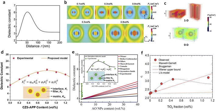 | ||
| Fig. 11 (a) Modelled dielectric constant of the PEI/Al2O3 nanocomposite in the interfacial region as a function of distance from the surface of the nanofiller. (b) Modelled polarizations of nanocomposites with nanofillers of 20 nm (upper) and 50 nm (lower) with varied filler contents on applying an electric field of 1 MV m−1. Figures (a) and (b) have been reproduced from ref. 36 with permission from The Royal Society of Chemistry, copyright 2017. (c) Simulated distribution of polarization in polymer composites with 1D and 0D nanofillers. This figure has been reproduced from ref. 41 with permission from Elsevier, copyright 2021. Experimental and modelled dielectric constants of (d) P(VDF-HFP)/CZS-APP, (e) PMMA/Al2O3, and PP/TiO2 nanocomposites as a function of nanofiller contents. Figure (d) has been reproduced from ref. 38 with permission from John Wiley and Sons, copyright 2021. Figure (e) has been reproduced from ref. 44 with permission from The Royal Society of Chemistry, copyright 2023. Figure (f) has been reproduced from ref. 87 with permission from the American Chemical Society, copyright 2021. | ||
5. Summary and outlook
Dilute nanocomposites are emerging as a significant advancement in developing scalable, high-energy-density polymer dielectrics. The unique phenomena and important effects such as dielectric enhancements, charge trapping and mechanical reinforcements in these nanocomposites distinctly differ from those in conventional polymer nanocomposites, which has led to unprecedented achievements in enhancing dielectric properties and capacitive energy storage performance at both room and elevated temperatures. Fundamentally, understanding the unconventional dielectric enhancements observed at low filler loadings has been greatly advanced through theoretical analyses and local structural characterization. A series of local structural and electrical changes such as chain distortion, free space expansion, and trapping site formation are found at polymer–filler interfaces, which are strongly correlated with the macroscopic properties of the nanocomposites. Moreover, various designing strategies from the perspectives of polymer and filler structures have been presented for further improving the overall performance of polymer nanocomposite dielectrics. With excellent scalability and high energy densities, these polymer nanocomposites are promising candidates for substituting current commercial dielectric polymers for high-energy-density polymer film capacitors. Additionally, this nanocomposite approach may provide opportunities for enhancing polarity-related functionalities, such as piezoelectric, pyroelectric and electrocaloric cooling. Despite these advances and promising applications, fundamental questions and technological challenges remain, including mechanisms and models for dielectric enhancements, inverse couplings at high temperatures, and issues related to scalability and reliability in large-area production. Addressing these challenges requires collaborative efforts across disciplines such as solid-state physics, polymer chemistry, nanotechnology, nanoscale characterization and computations.5.1 Upper limit of dielectric enhancements
The dielectric constants of dipolar linear dielectric polymers have been significantly improved through local structural changes induced by small-sized nanofillers at ultralow filling contents. The highest K achieved in these polymers is approaching a remarkably high value of 8, comparable to that of ferroelectric polymers.36,39,45 From a fundamental perspective, a key question is where the upper limit for K is and how to achieve it? This inquiry is crucial for the development of high-energy-storage polymer dielectrics and film capacitors across various applications. Systematic and in-depth investigations are needed to guide the design of polymer nanocomposites to further enhance K and energy storage performance at both room and elevated temperatures. In addition, attention to the preparation procedures for dilute nanocomposites is required, since the dielectric enhancement can be varied among batches (also manufactures) and also be affected by other factors such as solvents. Also, electrical testing conditions including frequency and electrode area should be carefully checked during measurements of dielectric properties and D–E loops for obtaining accurate capacitive performance. Results can be deceptive due to effects such as parasitic capacitance, which may become significant when electrode area decreases to a small scale (e.g., diameter <2 mm), leading to overestimated K and Ue.5.2 Dielectric enhancement mechanisms and models
A thorough understanding of dielectric enhancement is of critical importance for achieving high K and Ue in polymer nanocomposites with low filler contents. Despite extensive experimental and theoretical studies in recent years, fundamental questions and controversies persist. For instance, how can the exact contributions of enhanced dipolar responses be determined? What causes local chain conformation change and free space expansion near the filler surface? How can the seemingly contradictory effects of increased free volume on dipolar responses and electric breakdown paths be balanced? To address these questions, continuous efforts can be made on studying dielectric behaviours through broadband frequency- and temperature-dependent dielectric spectroscopy and examining chemical and physical changes at polymer–filler interfaces from a dynamic perspective using advanced microscopic methods. Additionally, theoretical efforts into dielectric modelling are important and imperative for overcoming the limitations of traditional models and guiding the design of high-performance polymer nanocomposite dielectrics. While phenomenological and interphase models have successfully described nanocomposites based on linear dipolar and ferroelectric polymers, they primarily apply to binary polymer composites. Further modifications are needed for models dealing with ternary or multi-component polymer composites.5.3 Critical inverse couplings at high temperatures
Although the dielectric constant and electric breakdown strength can be improved in nanocomposites with low filler contents at room temperature, achieving both high K and Eb at elevated temperatures remains challenging. For example, FPI/0.2 wt% PFNS with a high Eb of 800 MV m−1 at 200 °C exhibits a low K of 3.5, showing only a minor increase compared to pristine FPI.24 On the other hand, a PI nanocomposite with 1.0 vol% MgO demonstrates a high K of 7.5 but a low Eb of ∼300 MV m−1 at 150 °C.45 This dilemma may arise from at least two aspects. Firstly, local free volume created by filler doping can reduce constraints for dipoles but may also introduce weak points for electric tree propagation and decrease the local modulus, which become worse at elevated temperatures and high electric fields. Secondly, aggregations of fillers can damage dielectric enhancement effects and facilitate carrier transport between particles due to overlapping interfacial regions. In this sense, developing new structured fillers with high bandgaps and good interfacial interactions with the polymer matrix, along with tuning filler dimensions, are promising solutions to address these challenges.5.4 Artificial intelligence (AI)-assisted exploration of polymer nanocomposites
Compared to traditional development of polymer dielectrics that has relied on researchers' intuition and scientific understanding, rational material design, supported by artificial intelligence tools (such as machine learning approaches), may provide a more efficient paradigm for discovering new polymer dielectrics.88,89 For instance, density functional theory (DFT) and genetic algorithms have been used to predict polymers with high energy-storage potential, which have been experimentally confirmed.89 The AI-assisted polymer nanocomposite development is also promising, yet challenging due to their complexity and multi-component nature. Future advancements in high-performance polymer nanocomposite dielectrics will require interdisciplinary collaboration among material physics, chemistry, electrical engineering, and advanced computational techniques.5.5 Scalability, reliability, and practical applications in film capacitors
Currently reported high-performance polymer nanocomposite dielectrics are mainly produced on a small scale using laboratory techniques such as solution casting and layer-by-layer deposition. These nanocomposites exhibiting undesired uniformity and reliability are usually confronted with challenges in scalable production for real applications. In this context, addressing inhomogeneous filler dispersion in large-scale production is crucial, and monodispersing nanofillers throughout the polymer through advanced chemical design and fabrication methods is highly desired. Furthermore, factors such as mechanical properties, scalability, processability, and long-term reliability should also be considered for practical applications, in addition to the commonly reported energy-storage-related parameters. Laboratory-industry jointly supervised programs are underway to improve the scalability of dielectric films for capacitors, with expected progress in the future.Data availability
No primary research results, software or code have been included and no new data were generated or analysed as part of this review.Author contributions
L. Li: conceptualization, writing original draft, writing – review & editing, and visualization; W. Xu: format analysis; G. Rui: format analysis; S. Zhang: format analysis; Q. M. Zhang: writing – review & editing, supervision, project administration and funding acquisition; Q. Wang: conceptualization, writing – review & editing, supervision, project administration, and funding acquisition.Conflicts of interest
There are no conflicts to declare.Acknowledgements
This research was supported by the US Office of Naval Research (N000142312267, Q. W. and N00014-23-1-2247, Q. Z.)Notes and references
- Q. Li, L. Chen, M. R. Gadinski, S. Zhang, G. Zhang, H. U. Li, E. Iagodkine, A. Haque, L.-Q. Chen, T. N. Jackson and Q. Wang, Nature, 2015, 523, 576–579 CrossRef PubMed.
- J. Chen, Y. Zhou, X. Huang, C. Yu, D. Han, A. Wang, Y. Zhu, K. Shi, Q. Kang, P. Li, P. Jiang, X. Qian, H. Bao, S. Li, G. Wu, X. Zhu and Q. Wang, Nature, 2023, 615, 62–66 CrossRef PubMed.
- M. Yang, M. Guo, E. Xu, W. Ren, D. Wang, S. Li, S. Zhang, C.-W. Nan and Y. Shen, Nat. Nanotechnol., 2024, 1–16 Search PubMed.
- W. Sarjeant, IEEE Trans. Dielectr. Electr. Insul., 1990, 25, 861–922 CrossRef.
- H. Li, Y. Zhou, Y. Liu, L. Li, Y. Liu and Q. Wang, Chem. Soc. Rev., 2021, 50, 6369–6400 RSC.
- Q. Tan, P. Irwin and Y. Cao, IEEJ Trans. Fundam. Mater., 2006, 126, 1153–1159 CrossRef.
- Q.-K. Feng, S.-L. Zhong, J.-Y. Pei, Y. Zhao, D.-L. Zhang, D.-F. Liu, Y.-X. Zhang and Z.-M. Dang, Chem. Rev., 2021, 122, 3820–3878 CrossRef PubMed.
- R. W. Johnson, J. L. Evans, P. Jacobsen, J. R. Thompson and M. Christopher, IEEE Trans. Compon., Packag., Manuf. Technol., 2004, 27, 164–176 Search PubMed.
- M. Vujacic, M. Hammami, M. Srndovic and G. Grandi, Energies, 2017, 10, 1189 CrossRef.
- G. Wang, Z. Lu, Y. Li, L. Li, H. Ji, A. Feteira, D. Zhou, D. Wang, S. Zhang and I. M. Reaney, Chem. Rev., 2021, 121, 6124–6172 CrossRef CAS PubMed.
- B. Guo, F. Jin, L. Li, Z.-Z. Pan, X.-W. Xu and H. Wang, Rare Met., 2024, 43, 853–878 CrossRef CAS.
- L. Li, Y. Zhou, Y. Liu, X. Chen, Z. Han and Q. Wang, Appl. Phys. Lett., 2022, 120, 050502 CrossRef CAS.
- Q. Chen, Y. Shen, S. Zhang and Q. M. Zhang, Annu. Rev. Mater. Res., 2015, 45, 433–458 CrossRef CAS.
- X. Lu, X. Zou, J. Shen, L. Zhang, L. Jin and Z.-Y. Cheng, Nano Energy, 2020, 70, 104551 CrossRef CAS.
- G. Chen, J. Lin, X. Wang, W. Yang, D. Li, W. Ding, H. Li and Q. Lei, J. Mater. Sci.: Mater. Electron., 2017, 28, 13861–13868 CrossRef CAS.
- W. Sun, X. Lu, J. Jiang, X. Zhang, P. Hu, M. Li, Y. Lin, C.-W. Nan and Y. Shen, J. Appl. Phys., 2017, 121, 244101 CrossRef.
- L. Ren, L. Yang, S. Zhang, H. Li, Y. Zhou, D. Ai, Z. Xie, X. Zhao, Z. Peng, R. Liao and Q. Wang, Compos. Sci. Technol., 2021, 201, 108528 CrossRef CAS.
- D. Ai, H. Li, Y. Zhou, L. Ren, Z. Han, B. Yao, W. Zhou, L. Zhao, J. Xu and Q. Wang, Adv. Energy Mater., 2020, 10, 1903881 CrossRef.
- S. Luo, J. Yu, S. Yu, R. Sun, L. Cao, W.-H. Liao and C.-P. Wong, Adv. Energy Mater., 2019, 9, 1803204 CrossRef.
- X. Zhang, J. Jiang, Z. Shen, Z. Dan, M. Li, Y. Lin, C. W. Nan, L. Chen and Y. Shen, Adv. Mater., 2018, 30, e1707269 CrossRef PubMed.
- K. Stark and C. Garton, Nature, 1955, 176, 1225 Search PubMed.
- G. Zhang, Q. Li, E. Allahyarov, Y. Li and L. Zhu, ACS Appl. Mater. Interfaces, 2021, 13, 37939–37960 CrossRef.
- E. Allahyarov, Q. Li, T. Ju, Y.-W. Harn, H. Luo, D. Zhang, Z. Lin and L. Zhu, Chem. Eng. J., 2023, 463, 142490 CrossRef.
- M. Yang, H. Li, J. Wang, W. Shi, Q. Zhang, H. Xing, W. Ren, B. Sun, M. Guo, E. Xu, N. Sun, L. Zhou, Y. Xiao, M. Zhang, Z. Li, J. Pan, J. Jiang, Z. Shen, X. Li, L. Gu, C.-W. Nan, X. Wang and Y. Shen, Nat. Energy, 2024, 1–11 Search PubMed.
- Y. Zhou, C. Yuan, S. Wang, Y. Zhu, S. Cheng, X. Yang, Y. Yang, J. Hu, J. He and Q. Li, Energy Storage Mater., 2020, 28, 255–263 CrossRef.
- B. Liu, M. Yang, W.-Y. Zhou, H.-W. Cai, S.-L. Zhong, M.-S. Zheng and Z.-M. Dang, Energy Storage Mater., 2020, 27, 443–452 CrossRef.
- T. Zhang, X. Zhao, C. Zhang, Y. Zhang, Y. Zhang, Y. Feng, Q. Chi and Q. Chen, Chem. Eng. J., 2021, 408, 127314 CrossRef.
- L. Jin, J. Liu, L. Zhu, J. Ding, Y. Zhang and Z. Jiang, Compos. Sci. Technol., 2021, 213, 108949 CrossRef CAS.
- X. Ding, Z. Pan, Y. Cheng, H. Chen, Z. Li, X. Fan, J. Liu, J. Yu and J. Zhai, Chem. Eng. J., 2023, 453, 139917 CrossRef CAS.
- B. Xie, T. Wang, J. Cai, Q. Zheng, Z. Liu, K. Guo, P. Mao, H. Zhang and S. Jiang, Chem. Eng. J., 2022, 434, 134659 CrossRef.
- X. Wu, G. Song, W. Zhang, H. Feng, Y. Liu, E. Huang, X. Lin, Y. Yang and D. Q. Tan, J. Mater. Chem. A, 2022, 10, 13097–13105 RSC.
- X. Liang, Q. Li, Y. Ren, W. Xie, A. Tang and H. Yang, Adv. Funct. Mater., 2024, 2408719 CrossRef.
- Y. Guo, W. Zhao, D. Li, Y. Liu, L. Pang, Z. Shi, W. Liu, J. Su, G. Chen and D. Zhou, Compos. Sci. Technol., 2024, 248, 110477 CrossRef.
- L. Sun, Z. Shi, B. He, H. Wang, S. Liu, M. Huang, J. Shi, D. Dastan and H. Wang, Adv. Funct. Mater., 2021, 31, 2100280 CrossRef.
- Y. Jiang, J. Wang, S. Yan, Z. Shen, L. Dong, S. Zhang, X. Zhang and C.-W. Nan, Adv. Funct. Mater., 2022, 32, 2200848 CrossRef.
- Y. Thakur, T. Zhang, C. Iacob, T. Yang, J. Bernholc, L. Q. Chen, J. Runt and Q. M. Zhang, Nanoscale, 2017, 9, 10992–10997 RSC.
- T. Zhang, X. Chen, Y. Thakur, B. Lu, Q. Zhang, J. Runt and Q. M. Zhang, Sci. Adv., 2020, 6, eaax6622 CrossRef.
- L. Li, J. Cheng, Y. Cheng, T. Han, Y. Liu, Y. Zhou, G. Zhao, Y. Zhao, C. Xiong, L. Dong and Q. Wang, Adv. Mater., 2021, 33, 2102392 CrossRef.
- L. Li, J. Cheng, Y. Cheng, T. Han, Y. Liu, Y. Zhou, Z. Han, G. Zhao, Y. Zhao, C. Xiong, L. Dong and Q. Wang, J. Mater. Chem. A, 2021, 9, 23028–23036 RSC.
- B. Zhang, X. Chen, W. Lu, Q. M. Zhang and J. Bernholc, Nanoscale, 2021, 13, 10933–10942 RSC.
- X. Chen, T. Yang, Q. Zhang, L. Q. Chen, V. Bobnar, C. Rahn and Q. M. Zhang, Nano Energy, 2021, 106225 CrossRef.
- Prateek, V. K. Thakur and R. K. Gupta, Chem. Rev., 2016, 116, 4260–4317 CrossRef PubMed.
- X. Li, S. He, Y. Jiang, J. Wang, Y. Yu, X. Liu, F. Zhu, Y. Xie, Y. Li, C. Ma, Z. Shen, B. Li, Y. Shen, X. Zhang, S. Zhang and C.-W. Nan, Nat. Commun., 2023, 14, 5707 CrossRef.
- Y. Cheng, Y. Feng, Z. Pan, P. Wang, J. Liu, L. Liang, J. Yu, J. Zhai and Q. Wang, Energy Environ. Sci., 2023, 16, 5881–5890 RSC.
- P. Wang, Y. Guo, D. Zhou, D. Li, L. Pang, W. Liu, J. Su, Z. Shi and S. Sun, Adv. Funct. Mater., 2022, 32, 2204155 CrossRef CAS.
- Z. Dai, Z. Bao, S. Ding, C. Liu, H. Sun, H. Wang, X. Zhou, Y. Wang, Y. Yin and X. Li, Adv. Mater., 2021, 34, 2101976 CrossRef.
- L. Zhu, Y. Zhang, W. Xu, X. Zhu, S. Niu, Y. Zhang and Z. Jiang, Compos. Sci. Technol., 2022, 223, 109421 CrossRef.
- H. Hui, Y. Li, Y. Feng, J. Li, H. Zhao, C. Zhu, D. Yue, J. Yin and X. Liu, Polym. Adv. Technol., 2022, 33, 1685–1694 CrossRef.
- L. Li, J. Dong, R. Hu, X. Chen, Y. Niu and H. Wang, Chem. Eng. J., 2022, 435, 135059 CrossRef.
- O. Wiener, Phys. Z., 1904, 5, 332–338 Search PubMed.
- J. M. Garnett, Philos. Trans. R. Soc., A, 1904, 203, 385–420 Search PubMed.
- E. Tuncer, S. M. Gubański and B. Nettelblad, J. Appl. Phys., 2001, 89, 8092–8100 CrossRef.
- S. E. Skipetrov, Phys. Rev. B: Condens. Matter Mater. Phys., 1999, 60, 12705–12709 CrossRef.
- V. D. Bruggeman, Ann. Phys., 1935, 416, 636–664 CrossRef.
- A. H. Shivola, IEEE Trans. Geosci. Remote Sens., 1989, 27, 403–415 CrossRef.
- M. Yang, F. Yuan, W. Shi, W. Ren, M. Guo, C. Ouyang, L. Zhou, N. Sun, Y. Xiao, E. Xu, X. Zhang, Y. Wei, X. Deng, C. Nan, X. Wang and Y. Shen, Adv. Funct. Mater., 2023, 33, 2214100 CrossRef.
- H. Li, D. Ai, L. Ren, B. Yao, Z. Han, Z. Shen, J. Wang, L. Q. Chen and Q. Wang, Adv. Mater., 2019, e1900875 CrossRef.
- J. Jiang, Z. Shen, X. Cai, J. Qian, Z. Dan, Y. Lin, B. Liu, C.-W. Nan, L. Chen and Y. Shen, Adv. Energy Mater., 2019, 9, 1803411 CrossRef.
- J. Dong, R. Hu, Y. Niu, L. Li, S. Li, L. Sun, Y. Liu, X. Deng, L. Li, X. Xu, Z. Pan and H. Wang, Mater. Today Energy, 2022, 30, 101158 CrossRef.
- L. Tan, J. Dong, L. Li, C. Wang, Y. Liu, Y. Niu, Z. Pan, L. Sun and H. Wang, J. Materiomics, 2025, 11, 100852 CrossRef.
- H. Li, T. Yang, Y. Zhou, D. Ai, B. Yao, Y. Liu, L. Li, L.-Q. Chen and Q. Wang, Adv. Funct. Mater., 2021, 31, 2006739 CrossRef.
- L. Li, R. Feng, Y. Zhang and L. Dong, J. Mater. Chem. C, 2017, 5, 11403–11410 RSC.
- S. Wang, Z. Luo, J. Liang, J. Hu, N. Jiang, J. He and Q. Li, ACS Nano, 2022, 16, 13612–13656 CrossRef.
- L. Li, J. Cheng, Y. Cheng, T. Han, X. Liang, Y. Zhao, G. Zhao and L. Dong, J. Mater. Chem. A, 2020, 8, 13659–13670 RSC.
- X. Chen, H. Qin, Y. Liu, Y.-T. Lin, B. Zhang, W. Lu, S. H. Kim, J. Bernholc, Q. Wang and Q. M. Zhang, Appl. Phys. Lett., 2023, 122, 212901 CrossRef.
- W. Zhu, G. Rui, M. T. Wetherington, J. Lee, S. H. Kim and Q. M. Zhang, Appl. Phys. Lett., 2024, 124, 162901 CrossRef.
- W. Wang, D. Min and S. Li, IEEE Trans. Dielectr. Electr. Insul., 2016, 23, 564–572 Search PubMed.
- W. Ren, J. Pan, Z. Dan, T. Zhang, J. Jiang, M. Fan, P. Hu, M. Li, Y. Lin, C.-W. Nan and Y. Shen, Chem. Eng. J., 2020, 127614 Search PubMed.
- X. Qian, X. Chen, L. Zhu and Q. M. Zhang, Science, 2023, 380, eadg0902 CrossRef.
- B. Stadlober, M. Zirkl and M. Irimia-Vladu, Chem. Soc. Rev., 2019, 48, 1787–1825 RSC.
- L. Zhu and Q. Wang, Macromolecules, 2012, 45, 2937–2954 CrossRef.
- X. Zhang, B.-W. Li, L. Dong, H. Liu, W. Chen, Y. Shen and C.-W. Nan, Adv. Mater. Interfaces, 2018, 5, 1800096 CrossRef.
- N. A. Shepelin, P. C. Sherrell, E. N. Skountzos, E. Goudeli, J. Zhang, V. C. Lussini, B. Imtiaz, K. A. S. Usman, G. W. Dicinoski, J. G. Shapter, J. M. Razal and A. V. Ellis, Nat. Commun., 2021, 12, 3171 CrossRef PubMed.
- Y. Su, W. Li, X. Cheng, Y. Zhou, S. Yang, X. Zhang, C. Chen, T. Yang, H. Pan, G. Xie, G. Chen, X. Zhao, X. Xiao, B. Li, H. Tai, Y. Jiang, L.-Q. Chen, F. Li and J. Chen, Nat. Commun., 2022, 13, 4867 CrossRef PubMed.
- G. Tian, W. Deng, D. Xiong, T. Yang, B. Zhang, X. Ren, B. Lan, S. Zhong, L. Jin, H. Zhang, L. Deng and W. Yang, Cell Rep. Phys. Sci., 2022, 3, 100814 CrossRef.
- S. Cheng, S. J. Xie, J. Y. Carrillo, B. Carroll, H. Martin, P. F. Cao, M. D. Dadmun, B. G. Sumpter, V. N. Novikov, K. S. Schweizer and A. P. Sokolov, ACS Nano, 2017, 11, 752–759 CrossRef PubMed.
- M. Yang, S. Wang, J. Fu, Y. Zhu, J. Liang, S. Cheng, S. Hu, J. Hu, J. He and Q. Li, Adv. Mater., 2023, 35, 2301936 CrossRef.
- Y. Cheng, L. Li, C. H. Meredith, R. V. Balaj, D. Wang, M. Pan, T. Han, J. Yang, Q. Wang, L. Dong and L. D. Zarzar, ACS Mater. Lett., 2023, 5, 2074–2083 CrossRef.
- Y. Liu, Y. Zhou, H. Qin, T. Yang, X. Chen, L. Li, Z. Han, K. Wang, B. Zhang and W. Lu, Nat. Mater., 2023, 22, 873–879 CrossRef PubMed.
- H. Wang, Z. Hu, J. Pan, C. Zhong and E. Li, Chem. Eng. J., 2024, 483, 149300 CrossRef.
- Y. Liu, T. Yang, B. Zhang, T. Williams, Y.-T. Lin, L. Li, Y. Zhou, W. Lu, S. H. Kim, L.-Q. Chen, J. Bernholc and Q. Wang, Adv. Mater., 2020, 32, 2005431 CrossRef.
- T. Tanaka, M. Kozako, N. Fuse and Y. Ohki, IEEE Trans. Dielectr. Electr. Insul., 2005, 12, 669–681 CrossRef.
- T. Tanaka, IEEE Trans. Dielectr. Electr. Insul., 2005, 12, 914–928 CrossRef.
- T. Lewis, J. Phys. D: Appl. Phys., 2005, 38, 202 CrossRef.
- S. Peng, X. Yang, Y. Yang, S. Wang, Y. Zhou, J. Hu, Q. Li and J. He, Adv. Mater., 2019, 31, 1807722 CrossRef PubMed.
- S. Wu, J. Appl. Polym. Sci., 1988, 35, 549–561 CrossRef.
- X. Zhang, D. Zhu, H. You, Y. Hashimoto, T. Miyata, P. Chammingkwan and T. Taniike, ACS Appl. Electron. Mater., 2022, 4, 1257–1265 CrossRef.
- R.-L. Liu, J. Wang, Z.-H. Shen and Y. Shen, Energy Storage Mater., 2024, 71, 103612 CrossRef.
- R. Wang, Y. Zhu, J. Fu, M. Yang, Z. Ran, J. Li, M. Li, J. Hu, J. He and Q. Li, Nat. Commun., 2023, 14, 2406 CrossRef PubMed.
| This journal is © The Royal Society of Chemistry 2024 |
