Enzyme-loaded rod-like microgel shapes: a step towards the creation of shape-specific microreactors for blood detoxification purposes
Shahana
Bishnoi
 ab,
Michelle Maria Theresia
Jansman
 a,
Jiantao
Chen
a,
Peter Waaben
Thulstrup
a,
Jiantao
Chen
a,
Peter Waaben
Thulstrup
 c,
Stephan Sylvest
Keller
 b and
Leticia
Hosta-Rigau
 *a
*a
aDepartment of Health Technology, Centre for Nanomedicine and Theranostics, Technical University of Denmark, Nils Koppels Allé, Building 423, Kgs. Lyngby, 2800, Denmark. E-mail: leri@du.dk; Tel: +45258155
bNational Centre for Nano Fabrication and Characterization, Technical University of Denmark, Kgs, Lyngby, 2800, Denmark
cDepartment of Chemistry, University of Copenhagen, Universitetsparken 5, Copenhagen, 2100, Denmark
First published on 23rd April 2024
Abstract
Rapid removal of toxic substances is crucial to restore the normal functions of our body and ensure survival. Due to their high substrate specificity and catalytic efficiency, enzymes are unique candidates to deplete toxic compounds. While enzymes display several limitations including low stability and high immunogenicity, these can be overcome by entrapping them in a diverse range of carriers. The resulting micro/nanoreactors shield the enzymes from their surroundings, preventing their misfolding or denaturation thus allowing them to conduct their function. The micro/nanoreactors must circulate in the blood stream for extended periods of time to ensure complete depletion of the toxic agents. Surprisingly, while it is widely acknowledged that non-spherical carriers exhibit longer residence time in the bloodstream than their spherical counterparts, so far, all the reported micro/nanoreactors have been assembled with a spherical architecture. Herein, we address this important issue by pioneering the first shape-specific microreactors. We use UV-assisted punching to create rod-like microgel shapes with dimensions of 8 μm × 1 μm × 2 μm and demonstrate their biocompatibility by conducting hemolysis and cell viability assays with a macrophage and an endothelial cell line. Upon encapsulation of the model enzyme β-lactamase, the successful fabrication of rod-shaped microreactors is demonstrated by their ability to convert the yellow nitrocefin substrate into its hydrolyzed product.
1. Introduction
The burden of intoxication in the past 20 years has reached epidemic proportions, with hospitals routinely treating patients suffering from both accidental and intentional acute overdoses.1,2 This may be attributed to an escalation in the number of prescribed pharmaceuticals with high risk factors which, in turn, has boosted the number of mortalities associated with an overdose of analgesics, antidepressants, sedatives, stimulants and cardiovascular drugs.3 Additionally, acute intoxication may originate from the consumption of illicit drugs, suicidal attempts and/or environmental pollutants.4,5 Lastly, endogenous compounds produced by metabolic processes in our bodies may be another source of intoxication.4,5 For example, as seen with phenylketonuria or Fabry disease, an accumulation or overproduction of certain biochemicals due to innate defects in the expression of some enzymes, may result in life-threatening syndromes.4Unfortunately, there is still a lack of suitable, efficient and versatile detoxification therapies. This is highlighted by the fact that intentional and accidental drug poisoning is currently the leading cause of injury-related mortalities in the U.S., above both motor vehicle- and firearm-related deaths.6,7 Among existing intoxication therapies, extracorporeal dialysis with immobilized enzyme-devices or therapeutic plasma exchange have proven to be the most effective ones for the removal of toxic compounds. However, implementation of these therapies in the field is cumbersome and requires skilled personnel, thus excluding a fast, facile and ubiquitous application.5 This is a crucial shortcoming since, achieving a rapid reduction of the toxic load from the body, is essential in warranting survival.7 Administration of antidotes is another available approach. These antidotes are either high affinity scavengers that neutralize or adsorb toxic compounds or receptor antagonists that reverse the adverse effects caused by the toxicants.3,8,9 The challenge with this procedure is the limited number of available antidotes and the related undesired side effects.10
In this context, the catalytic conversion or biotransformation of toxic agents into non-toxic compounds is an attractive alternative with fewer side effects.11 Hence, enzymes hold a lot of potential in detoxification therapy, as they are exquisite biocatalysts with the ability to decompose substrate molecules with high specificity and efficiency.4 However, the use of enzymes is accompanied by important drawbacks which limit their in vivo applicability. Enzymes generally exhibit high immunogenicity, fast degradation and low circulating ability upon administration, overall resulting in their fast clearance from the bloodstream.4,11 Two main strategies are currently being pursued to overcome these limitations: the bioconjugation of enzymes to other proteins or polymers (e.g., conjugation to serum albumin, poly(ethylene glycol) (PEG) or dextran) or their entrapment within micro/nanocarriers.4,5 The latter approach, which entails the immobilization of an enzyme within a carrier matrix, has led to the development of enzymatic reactors.5 The enzymes encapsulated within such a matrix are stabilized and shielded from direct contact with the degrading components of the bloodstream such as proteases, opsonins and antibodies. Simultaneously, the semipermeable nature of the carrier allows for continuous diffusion of the toxic compounds and their degradation products across the encapsulating matrix.12 To date, enzymatic micro/nanoreactors have been successfully employed to deplete endogenous compounds such as reactive oxygen species,12,13 uric acid14 or phenylalanine,15 eliminate exogenous toxicants such as drugs7 and alcohols16 or industrial poisons like cyanide.11 For this, a wide range of carriers including polymers,17 polymeric capsules,18 liposomes,19 metal–organic-frameworks,20 mesoporous silica21 and their hybrid materials have been reported.4,5
An important consideration when designing micro/nanoreactors for detoxification purposes is that they should be able to evade the clearance systems in order to remain in blood circulation for long periods of time. This goal may be achieved by adjusting certain attributes of the micro/nanocarriers including their size, shape, composition and deformability. Such physicochemical features have been reported to profoundly affect the behavior of the carriers in a biological environment and, in turn, dictate their in vivo fate.22 While enzymatic reactors in a range of micro and nano-sizes and compositions have been successfully fabricated, variations in their shape have yet to be considered. Although, carrier shape has long been regarded a crucial determinant in its circulatory behavior, the vast majority of enzymatic reactors reported to this date display a spherical architecture.4,5 This lack of shape-specific enzymatic reactors may be attributed to the use of “bottom-up” fabrication methods. These techniques mainly render spherical shapes as a result of energy minimization and molecular self-assembly entropic effects.23 This is an important limitation, since recent theoretical modelling and experimental studies have demonstrated the benefits of anisotropic geometries in a hemodynamic flow environment.23 Additionally, non-spherical carriers are better at evading interactions with and uptake by the mononuclear phagocytic system (MPS).24 As such, rod-shaped nanocarriers have been more successful in escaping from the MPS and achieving prolonged circulation times than their spherical counterparts.22 Additionally, when comparing spherical particles and planar discs, the latter have demonstrated longer circulation residence time.24
In the current work, we fill this gap by creating rod-shaped enzymatic microreactors (MRs) for the first time. For this, we employ a “top-down” approach, where the geometric features of the carriers are predefined.25 Several template-based soft lithography techniques have been reported to fabricate shape-specific carriers including particle replication in non-wetting templates,26 continuous flow lithography27 and step-flash lithography.28 We have recently introduced UV-assisted punching as a novel microfabrication method to render non-spherical (circular, elliptical, square, and rod-like) planar geometries with a height of 25 μm and lateral dimensions of 25–100 μm.29 The resulting shape-specific microcarriers which were termed microgel shapes (MSs), were fabricated with PEG-based hydrogels. Hydrogels are an appealing option for the encapsulation of hydrophilic fragile biomolecules such as enzymes due to the amiable conditions provided by their three-dimensional (3D) polymer matrix with high water content.
Herein, to create shape-specific MRs with potential as detoxifying agents we: (i) push forward the concept of UV-assisted punching by fabricating rod-like MSs with a ∼10× downscaling in size, making them compatible with intravenous applications; (ii) assess their hemo- and biocompatibility and (iii) explore their potential as MRs by entrapping the model enzyme β-lactamase (β-Lact) within the hydrogel matrix and showcasing their ability to hydrolytically convert nitrocefin substrate.
2. Materials and methods
2.1. Materials
Zeonor® foils (188 μm thickness) were purchased from Microfluidic Chipshop (Jena, Germany). PEG monoacrylate (PEG-MA) (MW 400 Da) was purchased from Dayang Chem (Hangzhou) Co. Ltd. (Hangzhouzhejiang, China). PEG diacrylate (PEG-DA) (MW 4000 Da) was purchased from Polysciences Inc. (PA, USA). OxoidTM Nitrocefin solution and Cytiva Whatman™ Qualitative Filter Paper: Grade 1 circles were purchased from ThermoFisher Scientific (Roskilde, Denmark). 2-Carboxyethyl acrylate (CEA), Darocur®1173, fluorescein 5(6)-isothiocyanate (FITC), β-Lact from Enterobacter cloacae, sodium bicarbonate (NaHCO3), dimethyl sulfoxide (DMSO), phosphate buffered saline (PBS) tablets, isopropyl alcohol (IPA), penicillin/streptomycin, human umbilical vein endothelial cell line (HUVEC), Dulbecco's modified Eagle's medium-high glucose (DMEM D5796) and fetal bovine serum (FBS) were purchased from Merck Life Science A/S (Søborg, Denmark). Endothelial cell medium (ECM), and related 1% penicillin/streptomycin solution, 5% FBS, and 1% endothelial cell growth supplement were obtained from Innoprot (Derio-Biskaia, Spain). The RAW 264.7 cell line was obtained from the European Collection of Authenticated Culture Collections (ECACC, Wiltshire, United Kingdom). Ultrapure water (Milli-Q) was obtained from a Gradient A 10 system, resistance 18 MV cm, TOC < 4 ppb, EMD Millipore (USA). PBS and phosphate buffer (PB, 0.1 M at pH 7.0) were made using Milli-Q.Human blood was withdrawn from healthy donors at the Department of Health Technology, Technical University of Denmark (Kgs. Lyngby, Denmark). The blood withdrawal procedure was performed following approval, in accordance with the guidelines from the Regional Research Ethics Committee for the Capital Region of Denmark.
2.2. Fabrication of the silicon master and the polymeric stamps
A 4′′ Si master with four arrays of 3.41 × 3.41 cm2 was designed in CleWin 5 layout editor (WeWin software, The Netherlands). Each of the arrays contained a total of 21![[thin space (1/6-em)]](https://www.rsc.org/images/entities/char_2009.gif) 092
092![[thin space (1/6-em)]](https://www.rsc.org/images/entities/char_2009.gif) 400 rod-like entities with a nominal length of 10 μm, a width of 2.5 μm and a spacing of 1 μm between any two given entities. This design was employed to fabricate a Si master with a similar process as reported in detail elsewhere.29 In brief, a 1 μm thick SiO2 hard masking layer was patterned on the Si substrate by UV photolithography using a maskless aligner (MLA 150, s/n HI 1155, Heidelberg Instruments) and reactive ion etching (RIE) with an advanced oxide etcher (STS MESC Multiplex, UK). The SiO2 pattern was subsequently transferred into the Si substrate by RIE with an advanced Si etcher (STS MESC Multiplex ICP, UK) using an optimized process resulting in slightly tapered Si sidewalls. RIE was performed for 40 s to obtain an etch depth of 2 μm after removal of the SiO2 during 20 min in buffered HF (BHF). Next, the Si master was exposed to wet oxidation at 1100 °C for 50 min followed by removal of the oxide layer in BHF for 1 min. This additional step was introduced to smoothen the sidewalls of the Si master after RIE. A Zeiss Supra 40 VP scanning electron microscope (SEM) (Zeiss, Germany) at 5 kV in the secondary electron (SE) 2 detection mode was used to characterize the resulting microstructures. The Si master was coated with an antistiction layer of perfluorodecyltrichlorosilane (FDTS) by molecular vapor deposition (MVD100, Applied Microstructures Inc., USA).
400 rod-like entities with a nominal length of 10 μm, a width of 2.5 μm and a spacing of 1 μm between any two given entities. This design was employed to fabricate a Si master with a similar process as reported in detail elsewhere.29 In brief, a 1 μm thick SiO2 hard masking layer was patterned on the Si substrate by UV photolithography using a maskless aligner (MLA 150, s/n HI 1155, Heidelberg Instruments) and reactive ion etching (RIE) with an advanced oxide etcher (STS MESC Multiplex, UK). The SiO2 pattern was subsequently transferred into the Si substrate by RIE with an advanced Si etcher (STS MESC Multiplex ICP, UK) using an optimized process resulting in slightly tapered Si sidewalls. RIE was performed for 40 s to obtain an etch depth of 2 μm after removal of the SiO2 during 20 min in buffered HF (BHF). Next, the Si master was exposed to wet oxidation at 1100 °C for 50 min followed by removal of the oxide layer in BHF for 1 min. This additional step was introduced to smoothen the sidewalls of the Si master after RIE. A Zeiss Supra 40 VP scanning electron microscope (SEM) (Zeiss, Germany) at 5 kV in the secondary electron (SE) 2 detection mode was used to characterize the resulting microstructures. The Si master was coated with an antistiction layer of perfluorodecyltrichlorosilane (FDTS) by molecular vapor deposition (MVD100, Applied Microstructures Inc., USA).
The rod-like microstructure pattern from the Si master was then replicated into cyclo olefin polymer (COP) Zeonor foils by hot embossing in a similar manner as previously described.29 An assembly of the Si master and the COP foil was hot embossed in a plate to plate (P2P) nanoimprint lithography tool (CNI 2.0, NIL technology ApS, Denmark) at 180 °C for 10 min at a pressure of 6 bar under a vacuum of 25 mbar. The P2P chamber was maintained at a pressure of 6 bars until the temperature ramped down to 40 °C. After cooling, the hot embossed COP foil with microwells was manually demolded from the Si master. The wells in the COP foil were inspected by SEM using a TM3030Plus Tabletop Microscope (Hitachi, Germany). The micrographs were taken at a 15 kV voltage using a combination of the SE and backscattered electron detection modes. The height of the microstructures in Si and the depth of the microwells in COP were analyzed with a S Neox 3D optical profiler (Sensorfar, Spain) with a confocal objective. The line and the 3D profiles of the structures in Si and the wells in COP were rendered using Gwyddion by the Czech meteorology institute. The length and width of the microstructures in Si were characterized through image analysis by Image J.
2.3. Microgel shape fabrication and characterisation
The excess liquid surrounding the stamp was wicked away from the plate of the embosser and a 3.5 × 3.5 cm2 polyvinyl alcohol (PVA) foil was carefully assembled on top of the loaded stamp. To increase adhesion and remove any air pockets between the loaded stamp and the PVA foil, a rubber roller was gently rolled over the assembly. This assembly was then transferred to a P2P embosser (CNI 3.0, NIL technology ApS, Denmark) and UV-assisted punching was performed on the assembled stack under a 100 mbar vacuum. An imprint pressure of 7 bar was exerted and the stack was illuminated with 100 mW cm−2 UV light at 365 nm for 20 min while maintaining the pressure. Immediately after processing, the PVA foil with the punched MSs was demolded from the COP stamp.
The COP stamps were oxygen plasma treated for 30 s in a Semi Auto Plasma Processor 300 (PVA TePla, Germany) prior to FALD. The PVA was rinsed with IPA prior to use.
![[thin space (1/6-em)]](https://www.rsc.org/images/entities/char_2009.gif) 000 events were analyzed, with forward and sideward scattering thresholds of 10
000 events were analyzed, with forward and sideward scattering thresholds of 10![[thin space (1/6-em)]](https://www.rsc.org/images/entities/char_2009.gif) 000. These counts were corrected for any diluent events such as Milli-Q or buffer.
000. These counts were corrected for any diluent events such as Milli-Q or buffer.
2.4. MS biocompatibility
| Hemolysis rate (%) = ((sample − PBS control)/(Milli-Q control − PBS control)) × 100 | (1) |
Each condition was evaluated in duplicate in at least three independent experiments. The leftover samples after assessing the hemolysis rate assay were resuspended in PBS and imaged with BF light microscopy using the inverted microscope.
![[thin space (1/6-em)]](https://www.rsc.org/images/entities/char_2009.gif) 000 mL−1, respectively), endothelial cell growth supplements (1% v/v) and FBS (5% v/v). RAW 264.7 cells were cultured in DMEM enriched with streptomycin/penicillin (10 μg mL−1 and 1% v/v, U 10
000 mL−1, respectively), endothelial cell growth supplements (1% v/v) and FBS (5% v/v). RAW 264.7 cells were cultured in DMEM enriched with streptomycin/penicillin (10 μg mL−1 and 1% v/v, U 10![[thin space (1/6-em)]](https://www.rsc.org/images/entities/char_2009.gif) 000 mL−1, respectively) and FBS (10% v/v). Both cell lines were cultured in T75 culture flasks in a humidified incubator (5% CO2, 37 °C). The cell media was exchanged 2–3 times per week and the cells were sub-cultured when reaching ∼80% confluence. The HUVEC cells were detached by using trypsin, while the RAW 264.7 cells were detached from the flasks with a cell scraper. Next, both cell lines were re-suspended in fresh cell media and added into new T75 flasks at sub-cultivation ratios of 1
000 mL−1, respectively) and FBS (10% v/v). Both cell lines were cultured in T75 culture flasks in a humidified incubator (5% CO2, 37 °C). The cell media was exchanged 2–3 times per week and the cells were sub-cultured when reaching ∼80% confluence. The HUVEC cells were detached by using trypsin, while the RAW 264.7 cells were detached from the flasks with a cell scraper. Next, both cell lines were re-suspended in fresh cell media and added into new T75 flasks at sub-cultivation ratios of 1![[thin space (1/6-em)]](https://www.rsc.org/images/entities/char_2009.gif) :
:![[thin space (1/6-em)]](https://www.rsc.org/images/entities/char_2009.gif) 3 for HUVEC and 1
3 for HUVEC and 1![[thin space (1/6-em)]](https://www.rsc.org/images/entities/char_2009.gif) :
:![[thin space (1/6-em)]](https://www.rsc.org/images/entities/char_2009.gif) 5 for RAW 264.7 cells. Only cells within passages between 3–14 for HUVEC and 5–18 for RAW 264.7 were considered for the experiments.
5 for RAW 264.7 cells. Only cells within passages between 3–14 for HUVEC and 5–18 for RAW 264.7 were considered for the experiments.
![[thin space (1/6-em)]](https://www.rsc.org/images/entities/char_2009.gif) 000 HUVEC or 30
000 HUVEC or 30![[thin space (1/6-em)]](https://www.rsc.org/images/entities/char_2009.gif) 000 RAW 264.7 cells per well were seeded in a 96-well plate. After 24 h of incubation to allow for cell attachment, the cells were washed with PBS (2 × 150 μL) and incubated for 4 h with increasing quantities of MSs in PBS (0.5–8.0 × 10⁶ events). Next, the cells were washed with PBS (3 × 150 μL) and a PrestoBlue solution (100 μL, 10% v/v in cell media) was added to each of the wells, followed by 1 h incubation at 37 °C. The supernatants from the samples were transferred to a black 96-well plate to measure the fluorescent intensity (FI) (λex/λem: 535/615 nm) using the microplate reader. Media and cells only were set as negative and positive controls, respectively. The normalized cell viability (nCV) was calculated as follows:
000 RAW 264.7 cells per well were seeded in a 96-well plate. After 24 h of incubation to allow for cell attachment, the cells were washed with PBS (2 × 150 μL) and incubated for 4 h with increasing quantities of MSs in PBS (0.5–8.0 × 10⁶ events). Next, the cells were washed with PBS (3 × 150 μL) and a PrestoBlue solution (100 μL, 10% v/v in cell media) was added to each of the wells, followed by 1 h incubation at 37 °C. The supernatants from the samples were transferred to a black 96-well plate to measure the fluorescent intensity (FI) (λex/λem: 535/615 nm) using the microplate reader. Media and cells only were set as negative and positive controls, respectively. The normalized cell viability (nCV) was calculated as follows:| nCV (%) = ((sample − negative control)/(positive control − negative control)) × 100 | (2) |
Each condition was evaluated in triplicates in at least three independent studies.
2.5. MR fabrication
![[thin space (1/6-em)]](https://www.rsc.org/images/entities/char_2009.gif) 000 events were analyzed for each experiment.
000 events were analyzed for each experiment.
2.6. MR functional performance
| normalized Abs (nAbs) = Abs490 nm/Abs380 nm | (3) |
3. Results and discussion
3.1. Fabrication of the Si master and the polymeric stamps
Towards the development of shape-specific MRs, first MSs with a planar rod-like geometry were fabricated. This geometry was selected since planar and elongated carriers such as rods, elliptical discs and filomicelles have shown enhanced vascular residence times because they can align themselves to the streamlines of the blood flow.31,32 The long circulation in the bloodstream can also be attributed to the ability of such carriers to evade interactions and uptake by the MPS.24 For example, gold nanorods were shown to accumulate less in the liver in comparison to gold spheres. This can be attributed to an enhanced residence time for the nanorods which, in turn, increased their accumulation in tumours.32 The size of the carriers also has a profound impact on their in vivo fate. Spherical nanocarriers with diameters of less than 10 nm are easily removed from the body through renal clearance. Likewise, microcarriers with diameters of 1–3 μm are also removed rapidly from circulation due to higher opsonization and subsequent clearance by the MPS system in the liver and spleen.22 In contrast, microcarriers larger than 5 μm in diameter experience decreased RBC-collision induced margination effect and thus have a lower propensity to bind to the endothelium.23 Furthermore, microcarriers larger than 10 μm can block the microcirculation at high concentrations. Based on these considerations, to potentially achieve long circulation times, we aimed at fabricating MSs that are larger than 5 μm and smaller than 10 μm. Furthermore, the aspect ratio of non-spherical carriers is also an important consideration during their design since internalization by the MPS is less probable for carriers with high aspect ratio.33 Thus, as a first step, an Si master was designed with large arrays of rod-like microstructures having nominal dimensions of 10 μm, 2.5 μm and 2 μm for length, width and height, respectively, corresponding to an aspect ratio of 4![[thin space (1/6-em)]](https://www.rsc.org/images/entities/char_2009.gif) :
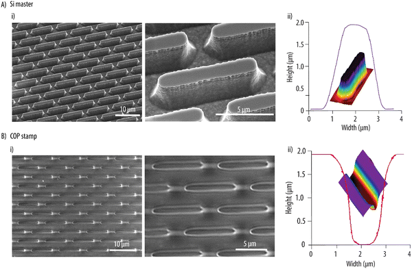
:![[thin space (1/6-em)]](https://www.rsc.org/images/entities/char_2009.gif) 1. Furthermore, a nominal spacing of 1 μm between two consecutive entities was selected to facilitate UV-assisted punching in the next steps. The Si wafer was patterned by maskless UV photolithography and RIE. A 0.6 ± 0.2 μm (SD, n = 5) loss in resolution was observed during the photolithographic pattern transfer. This, combined with isotropic etching due to the additional oxidation and oxide removal step after RIE, resulted in Si microstructures with lateral dimensions lower than the nominal values. After fabrication, the rod-like Si microstructures had a length of 8.4 ± 0.2 μm (SD, n = 5), a width of 1.0 ± 0.1 μm (SD, n = 5) and a height of 2.0 ± 0.1 μm (SD, n = 5) (Fig. 1Ai), resulting in a higher aspect ratio as designed. The microfabricated structures also had slightly curved sidewalls to aid in demolding in the subsequent steps. Next, the Si master was employed to hot emboss microwells into a COP foil and form an inverse replica. While the hot embossing was performed at a process temperature of 180 °C as previously reported, the release temperature for the process had to be decreased to 40 °C to ensure complete reflow and solidification of the polymer and obtain a good replication of the microstructures. The hot embossed COP stamp with microwells of 2.1 ± 1.0 μm (SD, n = 5) in depth is shown in Fig. 1Bi. A high replication fidelity was obtained as demonstrated by the SEM micrographs and the 3D profile measurements shown in Fig. 1Aii and Bii for the Si master and the COP stamp, respectively.
1. Furthermore, a nominal spacing of 1 μm between two consecutive entities was selected to facilitate UV-assisted punching in the next steps. The Si wafer was patterned by maskless UV photolithography and RIE. A 0.6 ± 0.2 μm (SD, n = 5) loss in resolution was observed during the photolithographic pattern transfer. This, combined with isotropic etching due to the additional oxidation and oxide removal step after RIE, resulted in Si microstructures with lateral dimensions lower than the nominal values. After fabrication, the rod-like Si microstructures had a length of 8.4 ± 0.2 μm (SD, n = 5), a width of 1.0 ± 0.1 μm (SD, n = 5) and a height of 2.0 ± 0.1 μm (SD, n = 5) (Fig. 1Ai), resulting in a higher aspect ratio as designed. The microfabricated structures also had slightly curved sidewalls to aid in demolding in the subsequent steps. Next, the Si master was employed to hot emboss microwells into a COP foil and form an inverse replica. While the hot embossing was performed at a process temperature of 180 °C as previously reported, the release temperature for the process had to be decreased to 40 °C to ensure complete reflow and solidification of the polymer and obtain a good replication of the microstructures. The hot embossed COP stamp with microwells of 2.1 ± 1.0 μm (SD, n = 5) in depth is shown in Fig. 1Bi. A high replication fidelity was obtained as demonstrated by the SEM micrographs and the 3D profile measurements shown in Fig. 1Aii and Bii for the Si master and the COP stamp, respectively.
3.2. Fabrication and characterization of microgel shapes
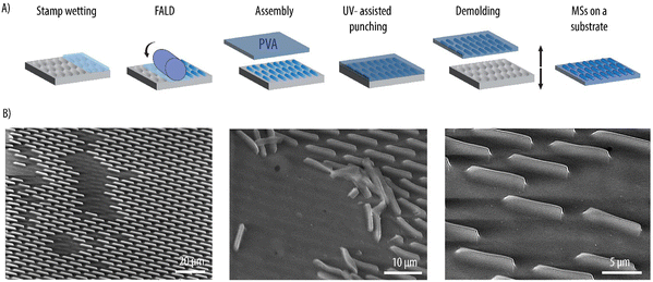
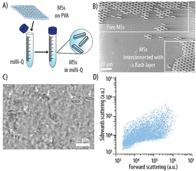
Rod-like MSs were fabricated by FALD and UV-assisted punching as illustrated in Fig. 2A. Here, PEG-based hydrogels were the carrier of choice since the MSs are envisioned as novel enzymatic reactors. Hydrogels were chosen over other immobilization materials since, due to their high-water content, they provide a well-suited microenvironment for enzymes. Amongst different hydrogel materials, PEG is of particular interest. This is because, in addition to being biocompatible and already approved by the U.S. Food and Drug Administration (FDA) for intravenous application, PEG coatings have demonstrated to play a pivotal role in preventing opsonization and the subsequent MPS removal. This, in turn, prolongs carrier circulation times in vivo.34,35 Thus, a PEG-based formulation consisting of PEG-MA as the main polymeric backbone, PEG-DA as the crosslinker, CEA to provide a negative charge and a photoinitiator, was employed as reported earlier. Although PEG can be degraded through hydrolysis, we would like to note that in further studies involving in vivo investigations, the MSs can be assembles using biodegradable crosslinkers (e.g., containing disulfide bonds) to aid in the degradation of the carriers once their task has been fulfilled.To downscale the dimensions of the rod-like MSs with a factor of 10 compared to our previous study, re-optimization of the fabrication method was required. Previously during FALD, to ensure the adhesion of the PVA to the loaded stamp and subsequent carrier formation, an additional thin film of the hydrogel precursor formulation was deposited on the already loaded stamp.29 Here, such a step was not required, and the hydrogel precursor formulation was loaded in the stamp wells in succession as the stamp passed through the nip zone of a R2P embosser during FALD. The microscopic evaluation of the loaded stamp revealed that the wells were indeed filled with a thin film covering the entire stamp surface (data not shown). Next, a PVA foil was laminated with a rubber roller onto the loaded stamp prior to transfer to a P2P embosser. The lamination step was conducted immediately after FALD to prevent evaporation of water from the aqueous hydrogel formulation, which could lead to its non-uniform adhesion of the PVA. A PVA foil slightly larger in size than the stamp was employed to facilitate the manual demolding in the following steps. Next, UV-assisted punching was performed. A continued pressure of 7 bars was applied to the assembly, while exposing it to UV light at 365 nm for 20 min. While the hydrogel precursor formulation was photocured, the thin walls of the stamp applied shear stress and punched through the hydrogel flash layer and partially into the PVA substrate thus transferring the MSs to this substrate. The assembly was then demolded manually to obtain MSs with a height of 2.2 ± 1.0 μm on the PVA substrate (Fig. 2B). Water soluble PVA was chosen as the substrate to facilitate the harvesting of the MSs avoiding additional transfer steps during fabrication. The PVA foil was dissolved in Milli-Q to obtain a MS suspension (Fig. 3A). Fig. 3B shows how, after UV-assisted punching, both individual MSs and MSs connected with intermittent flash layer were transferred to the PVA. Nonetheless, a filtration step yielded a suspension with individual MSs that were free from large interconnecting flash layer and aggregates (Fig. 3C). The MSs displayed the expected rod-like shape of the master and stamp used for their fabrication as well as the targeted dimensions. The MSs were quantified by flow cytometry by monitoring the forward and sidewards light scattering (Fig. 3D). The elongated shape of the observed plot could be attributed to the anisotropic shape of the MSs which, depending on the position when encountering the laser light, scatters the light differently.
3.3. Microgel shape biocompatibility
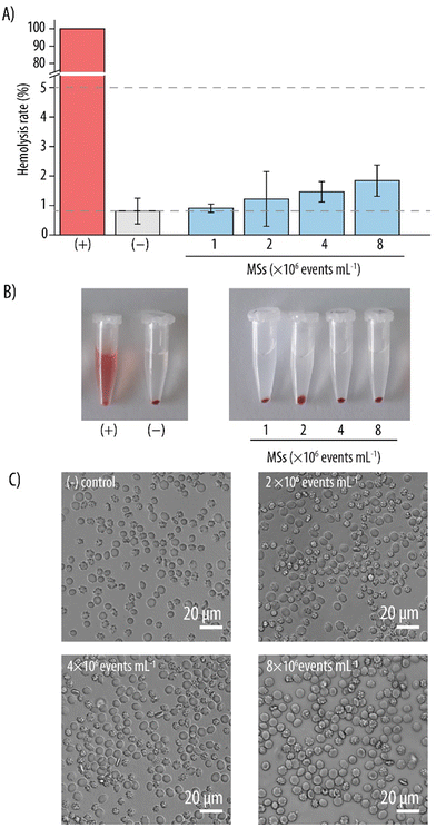
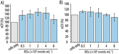
Biocompatibility is an essential feature for carriers intended for clinical use to avoid unforeseen side-effects. Although the MSs were fabricated with PEG, which is an FDA-approved material, it was still imperative to verify this presumed biocompatibility. Therefore, the interaction of the MSs with various cell lines was evaluated. Since MSs are envisioned as carriers for intravenous administration, they will inevitably be in contact with the RBCs present in the blood stream. Thus, we first assessed the hemocompatibility of the MSs with a hemolysis rate assay, which measures the % of hemoglobin release from potentially lysed RBCs. Fig. 4A shows that, for the lowest MS concentration studied (i.e., 1 × 10⁶ events mL−1), the hemolysis rate was similar to that of the negative control (∼1%) indicating no RBC lysis. At higher MS concentrations (i.e., 2–8 × 10⁶ events mL−1), a slight increase in hemolysis rate was observed. However, the values were up to 2% and still well below 5%. Since, according to ISO 10993-4, nanomaterials that promote a hemolysis rate below 5% can be considered as non-hemolytic, we deemed these newly developed MSs as hemocompatible in the studied concentration range.36 These results were consistent with the visual assessment of the different MS suspensions against the controls (Fig. 4B). After centrifugation of the samples to separate the RBCs and the MSs from the released hemoglobin, only the positive control containing fully lysed RBCs showed the reddish color which can unequivocally be attributed to free hemoglobin. In contrast, a clear supernatant indicating intact RBCs was observed for both the negative control and the different MS suspensions which clearly concurs with the observed low hemolysis rates. The blood cells from the pellets were imaged with light microscopy to visually assess any potential morphological changes. Fig. 4C shows no apparent morphological differences between the cells of the negative control of PBS only and the blood cells incubated with the MSs.Once the MS hemocompatibility had been verified, their biocompatibility was further assessed with other cell lines relevant in the context of intravenous delivery. Thus, cell viability assays were conducted with HUVECs and RAW 264.7 cells. HUVECs were chosen as an in vitro model of the endothelial cells constituting the innermost layer of the blood vessels. Since RAW 264.7 cells are a type of murine macrophages, they were selected due to their function as the main cells responsible for the removal of foreign objects from the bloodstream. For this, MS suspensions in the same concentration range as for the hemolysis rate assay (1–8 × 10⁶ events mL−1) were incubated with the respective cell lines for 4 h and the nCV was assessed post incubation. Fig. 5 indicates no decrease in the nCV for either of the two cell lines for all the studied concentrations. In contrast, incubation with the MSs promoted an increase in nCV which was more pronounced for the HUVEC cell line. Specifically, a maximum increase in nCV up to ∼150% was observed for HUVECs, whereas the increase in nCV for RAW 264.7 cells was ∼110%. This may be attributed to the intrinsic properties of hydrogels mimicking the extracellular matrix. As such, hydrogels have previously demonstrated the ability to enhance cell proliferation when used as scaffolds in cell cultures.37 Furthermore, hydrogels have also been employed for cell encapsulation purposes because of their hydrophilic environment.38 For RAW 264.7, MS concentrations as high as 8 × 10⁶ events mL−1 promoted a decrease in nCV as compared to the control of cells only, indicating that the maximum non-toxic concentration for this cell line had already been reached.
3.4. Microreactor fabrication
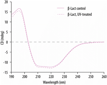
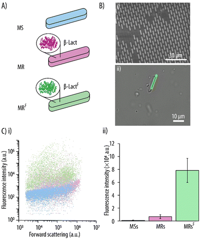
In our earlier work, MSs encapsulating bovine serum albumin had been successfully fabricated by incorporating the protein into the hydrogel precursor formulation.29 Herein, we push the concept further by encapsulating a functional enzyme. For this, firstly, it was essential to exclude any potential detrimental effects on the enzymes from the UV irradiation and the associated increased temperature during UV-assisted punching. Since preservation of an enzyme's secondary structure is essential in retaining its functionality, the effect of UV on it was studied prior to fabrication of MRs. β-Lact was chosen as the model enzyme because its activity can be visualized and quantified by monitoring the conversion of nitrocefin, a yellow enzymatic substrate, into its hydrolyzed red product. Thus, β-Lact enzyme in its free form was exposed to similar UV conditions as it would experience during the MR fabrication process and its secondary structure was evaluated by CD. Fig. 6 shows the typical absorption peaks of an α-helical structure for β-Lact,39 that is, a maximum at 196 nm and a double minimum at 212 and 220 nm. Importantly, no noticeable changes could be detected for the β-Lact that had been exposed to UV irradiation, which suggests that the α-helical structure of β-Lact was well preserved.Next, the MRs were fabricated by incorporating the enzyme in the hydrogel precursor formulation. As a first step and to verify the successful incorporation of the enzyme within the MSs, fluorescently labelled β-LactF was employed (Fig. 7Ai). Fig. 7Bi shows a SEM micrograph of the β-LactF -loaded MRs on the PVA substrate after demolding, which confirms morphological similarity to the empty MSs (see Fig. 3B). Fig. 7Bii shows an overlay of BF and fluorescence images of the MRs after being harvested from the PVA substrate. The MRs were monodispersed, non-aggregated and maintained their rod-like morphology. Additionally, a homogeneous green signal arising from the rod-like MRs confirmed the successful encapsulation of β-LactF. The incorporation of the β-LactF was further evaluated by flow cytometry using fluorescence and light-scattering parameters (Fig. 7Ci). The forward scattered light was similar for empty MSs, β-Lact-loaded MRs and β-LactF-loaded MRs (MRFs), which was to be expected since they all display the same shape and size. Quantification of the FI of the individual MSs and MRs shows a slight increase (i.e., of 7.5-fold) in FI upon encapsulation of the non-fluorescently labelled β-Lact (Fig. 7Cii). This can be attributed to the autofluorescence of β-Lact which is a result of its high content of tryptophan, tyrosine and phenylalanine. However, a pronounced 90-fold increase in FI was observed for the MRFs. Thus, incorporation of the fluorescently labelled β-LactF resulted in a further 11.7-fold increase in FI for the MRFs.
3.5. Microreactor functionality
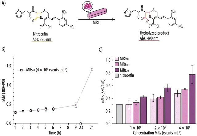
To confirm the retention of enzymatic activity of β-Lact within the MRs, they were incubated with the yellow nitrocefin substrate and the nAbs due to the red hydrolyzed product was monitored over time (Fig. 8A). Fig. 8B shows this increment in nAbs over time for MRs assembled using a β-Lact concentration of 10 mg mL−1 (i.e., MRs10). Specifically, there was a 1.5-fold increase in nAbs after 9 h of incubation, and a further 3.1-fold increase after 24 h. Several concentrations of MR (i.e., 1 × 10⁶, 2 × 10⁶ and 4 × 10⁶ events mL−1) loaded with different amounts of β-Lact (i.e., 10, 15 and 20 mg mL−1) were considered. Fig. 8C shows that the enzymatic reaction was dependent on both the number of MRs and on the loading of β-Lact. For example, for the highest β-Lact concentration (i.e., 20 mg mL−1), doubling the number of MRs (i.e., from 1 × 10⁶ to 2 × 10⁶ events mL−1) resulted in a 1.35-fold increase in nAbs. Upon doubling the number of MRs again, a further 1.37 increase in nAbs was also detected. Similarly, for the highest studied concentration of MRs (i.e., 4 × 10⁶ events mL−1), increasing the β-Lact concentration from 10 to 15 mg mL−1 promoted a 1.15-fold increase in nAbs and a further 1.42-fold increase was observed when the β-Lact was increased to 20 mg mL−1.These results indicate the formation of hydrolyzed nitrocefin product and, in turn, that shape-specific MRs with catalytic activity had successfully been fabricated. Furthermore, the hydrolysis of nitrocefin could be controlled by either varying the amount of loaded β-Lact or by varying the concentrations of MRs.
4. Conclusions
Here, we have reported the fabrication of shape-specific microreactors for the first time. We have previously introduced UV-assisted punching as a highly versatile method to fabricate size- and shape-specific highly monodisperse microcarriers. In this work, we have shown that this microfabrication approach is also a benign method that can be used to encapsulate fragile biomolecules such as enzymes by simply incorporating them within the hydrogel precursor formulation. Specifically, the model enzyme β-Lact has been loaded into PEG-based rod-like MSs that are 8 μm in length 1 μm in width and 2 μm in height. These dimensions are a factor of 10 smaller than what has been achieved earlier with UV-assisted punching, demonstrating the versatility of the fabrication method. We have demonstrated preservation of the β-Lact activity, since the resulting microreactors are able to convert the substrate nitrocefin into its hydrolyzed product. Furthermore, the hydrolysis of nitrocefin could be controlled by either varying the amount of loaded enzyme or by using different amounts of microreactors.To maximize the therapeutic effect, micro/nanoreactors should circulate in the blood stream for long periods of time. In this context, it has been well established that the physiochemical properties of the carriers including composition, size, surface chemistry and shape have a profound effect on their physiological interactions including opsonization, MPS uptake, cell internalization, margination or circulation half-life. Future work will involve a systematic study spanning a range of carriers of different sizes, geometries (from spheres-to-spheroids-to-discs-to-rods) and elasticities to identify the features promoting the longest circulation times in vivo.
We anticipate microreactors fabricated by UV-assisted punching will have a central role in the treatment of important disease states such as cancer (i.e., to transform certain biochemicals that are essential for its progression), in inflammatory processes (i.e., for the depletion of oxygen species), for the detoxification of drugs and other xenobiotics or for the correction of metabolic and genetic defects that result in the overproduction of a certain metabolite.
Conflicts of interest
There are no conflicts to declare.Acknowledgements
The authors would also like to thank Mariana Filipa De Abreu Alves and the fabrication support staff at DTU Nanolab cleanroom facilities for providing help with various fabrication and characterization processes. This work has been supported by the Danish Council for Independent Research (Grant No. 6111-00298B) and by the European Research Council under the European Union's Horizon 2020 Research and Innovation Program (Grant No. 101002060).References
- L. J. Paulozzi, Prescription Drug Overdoses: A Review, J. Saf. Res., 2012, 43(4), 283–289, DOI:10.1016/J.JSR.2012.08.009
.
- D. D. Gummin, J. B. Mowry, M. C. Beuhler, D. A. Spyker, A. C. Bronstein, L. J. Rivers, N. P. T. Pham and J. Weber, 2020 Annual Report of the American Association of Poison Control Centers’ National Poison Data System (NPDS): 38th Annual Report, 2021, 59(12), 1282–1501 DOI:10.1080/15563650.2021.1989785.
- J. C. Leroux, Injectable Nanocarriers for Biodetoxification, Nat. Nanotechnol., 2007, 2(11), 679–684, DOI:10.1038/nnano.2007.339
.
- Y. Liu, J. Li and Y. Lu, Enzyme Therapeutics for Systemic Detoxification, Adv. Drug Delivery Rev., 2015, 90, 24–39, DOI:10.1016/J.ADDR.2015.05.005
.
- T. N. Pashirova, A. Bogdanov and P. Masson, Therapeutic Nanoreactors for Detoxification of Xenobiotics: Concepts, Challenges and Biotechnological Trends with Special Emphasis to Organophosphate Bioscavenging, Chem. – Biol. Interact., 2021, 346, 109577, DOI:10.1016/J.CBI.2021.109577
.
- L. M. Rossen, D. Khan and M. Warner, Trends and Geographic Patterns in Drug-Poisoning Death Rates in the U.S., 1999–2009, Am. J. Prev. Med., 2013, 45(6), e19–e25, DOI:10.1016/J.AMEPRE.2013.07.012
.
- V. Förster and J. C. Leroux, Nano-Antidotes for Drug Overdose and Poisoning, Sci. Transl. Med., 2015, 7(290), 1–14, DOI:10.1126/SCITRANSLMED.3008736/ASSET/8982F34F-F186-4F11-9A76-72AD54B69171/ASSETS/GRAPHIC/7290PS14_F3.JPEG
.
- P. W. Elsinghorst, F. Worek, H. Thiermann and T. Wille, Drug Development for the Management of Organophosphorus, Expert Opin. Drug Discovery, 2013, 8(12), 1467–1477, DOI:10.1517/17460441.2013.847920
.
- M. K. Johnson, D. Jacobsen, T. J. Meredith, P. Eyer, A. J. Heath, D. A. Ligtenstein, T. C. Marrs, L. Szinicz, J. A. Vale and J. A. Haines, Evaluation of Antidotes for Poisoning by Organophosphorus Pesticides, Emerg. Med., 2000, 12(1), 22–37, DOI:10.1046/J.1442-2026.2000.00087.X
.
- L. Zhang and J. C. Leroux, Current and Forthcoming Approaches for Systemic Detoxification, Adv. Drug Delivery Rev., 2015, 90, 1–2, DOI:10.1016/J.ADDR.2015.07.010
.
- M. Szilasi, M. Budai, L. Budai and I. Petrikovics, Nanoencapsulated and Microencapsulated Enzymes in Drug Antidotal Therapy, Toxicol. Ind. Health, 2012, 28(6), 522–531, DOI:10.1177/0748233711416946
.
- M. J. York-Duran, M. Godoy-Gallardo, M. M. T. Jansman and L. Hosta-Rigau, A Dual-Component Carrier with Both Non-Enzymatic and Enzymatic Antioxidant Activity towards ROS Depletion, Biomater. Sci., 2019, 7(11), 4813–4826, 10.1039/C9BM00913B
.
- M. Godoy-Gallardo, M. J. M. J. York-Duran and L. Hosta-Rigau, Recent Progress in Micro/Nanoreactors toward the Creation of Artificial Organelles, Adv. Healthcare Mater., 2018, 7(5), 1700917, DOI:10.1002/adhm.201700917
.
- J. Ming, T. Zhu, J. Li, Z. Ye, C. Shi, Z. Guo, J. Wang, X. Chen, N. Zheng, J. Ming, T. B. Zhu, Z. C. Ye, J. J. Wang, X. L. Chen, N. F. Zheng, J. C. Li, C. R. Shi and Z. D. Guo, A Novel Cascade Nanoreactor Integrating Two-Dimensional Pd-Ru Nanozyme, Uricase and Red Blood Cell Membrane for Highly Efficient Hyperuricemia Treatment, Small, 2021, 17(46), 2103645, DOI:10.1002/SMLL.202103645
.
- L. Hosta-Rigau, M. J. York-Duran, T. S. Kang and B. Städler, Extracellular Microreactor for the Depletion of Phenylalanine toward Phenylketonuria Treatment, Adv. Funct. Mater., 2015, 25(25), 3860–3869, DOI:10.1002/adfm.201404180
.
- Y. Liu, J. Du, M. Yan, M. Y. Lau, J. Hu, H. Han, O. O. Yang, S. Liang, W. Wei, H. Wang, J. Li, X. Zhu, L. Shi, W. Chen, C. Ji and Y. Lu, Biomimetic Enzyme Nanocomplexes and Their Use as Antidotes and Preventive Measures for Alcohol Intoxication, Nat. Nanotechnol., 2013, 8(3), 187–192, DOI:10.1038/nnano.2012.264
.
- I. Petrikovics, S. I. Baskin, K. M. Beigel, B. J. Schapiro, G. A. Rockwood, A. B. W. Manage, M. Budai and M. Szilasi, Nano-Intercalated Rhodanese in Cyanide Antagonism, Nanotoxicology, 2010, 4(2), 247–254, DOI:10.3109/17435390903528254
.
- W. Wei, J. Du, J. Li, M. Yan, Q. Zhu, X. Jin, X. Zhu, Z. Hu, Y. Tang and Y. Lu, Construction of Robust Enzyme Nanocapsules for Effective Organophosphate Decontamination, Detoxification, and Protection, Adv. Mater., 2013, 25(15), 2212–2218, DOI:10.1002/ADMA.201205138
.
- Q. Y. Tan, N. Wang, H. Yang, L. Chen, H. R. Xiong, L. K. Zhang, J. Liu, C. J. Zhao and J. Q. Zhang, Preparation and Characterization of Lipid Vesicles Containing Uricase, Drug Delivery, 2010, 17(1), 28–37, DOI:10.3109/10717540903508953
.
- H. Li, L. Ma, L. Zhou, J. Gao, Z. Huang, Y. He and Y. Jiang, Magnetic Integrated Metal/Enzymatic Nanoreactor for Chemical Warfare Agent Degradation, Colloids Surf., A, 2019, 571, 94–100, DOI:10.1016/J.COLSURFA.2019.03.061
.
- Y. Zhu, H. Shi, T. Li, J. Yu, Z. Guo, J. Cheng and Y. Liu, A Dual Functional Nanoreactor for Synergistic Starvation and Photodynamic Therapy, ACS Appl. Mater. Interfaces, 2020, 12(16), 18309–18318, DOI:10.1021/ACSAMI.0C01039/SUPPL_FILE/AM0C01039_SI_001.PDF
.
- S. Nejati, E. Mohseni Vadeghani, S. Khorshidi and A. Karkhaneh, Role of Particle Shape on Efficient and Organ-Based Drug Delivery, Eur. Polym. J., 2020, 122, 109353, DOI:10.1016/J.EURPOLYMJ.2019.109353
.
- A. Sen Gupta, Role of Particle Size, Shape, and Stiffness in Design of Intravascular Drug Delivery Systems: Insights from Computations, Experiments, and Nature, Wiley Interdiscip. Rev. Nanomed. Nanobiotechnol., 2016, 8(2), 255–270, DOI:10.1002/WNAN.1362
.
- S. Muro, C. Garnacho, J. A. Champion, J. Leferovich, C. Gajewski, E. H. Schuchman, S. Mitragotri and V. R. Muzykantov, Control of Endothelial Targeting and Intracellular Delivery of Therapeutic Enzymes by Modulating the Size and Shape of ICAM-1-Targeted Carriers, Mol. Ther., 2008, 16(8), 1450–1458, DOI:10.1038/mt.2008.127
.
- T. L. Moore, A. B. Cook, E. Belotti, R. Palomba, P. Manghnani, R. Spanò, S. Brahmachari, M. Di Francesco, A. L. Palange, D. Di Mascolo and P. Decuzzi, Shape-Specific Microfabricated Particles for Biomedical Applications: A Review, Drug Delivery Transl. Res., 2022, 1–19, DOI:10.1007/S13346-022-01143-4
.
- J. M. DeSimone, Co-Opting Moore's Law: Therapeutics, Vaccines and Interfacially Active Particles Manufactured via PRINT®, J. Controlled Release, 2016, 240, 541–543, DOI:10.1016/J.JCONREL.2016.07.019
.
- J. H. Jang, D. Dendukuri, T. A. Hatton, E. L. Thomas and P. S. Doyle, A Route to Three-Dimensional Structures in a Microfluidic Device: Stop-Flow Interference Lithography, Angew. Chem., Int. Ed., 2007, 46(47), 9027–9031, DOI:10.1002/ANIE.200703525
.
- M. Caldorera-Moore, M. K. Kang, Z. Moore, V. Singh, S. V. Sreenivasan, L. Shi, R. Huang and K. Roy, Swelling Behavior of Nanoscale, Shape- and Size-Specific, Hydrogel Particles Fabricated Using Imprint Lithography, Soft Matter, 2011, 7(6), 2879–2887, 10.1039/C0SM01185A
.
- S. Bishnoi, X. Liu, L. H. E. Thamdrup, R. S. Petersen, L. Hosta-Rigau and S. S. Keller, UV-Assisted Punching of Microgel Shapes for Oral Biomacromolecule Delivery, Microsyst. Nanoeng., 2023, 20, 100221, DOI:10.1016/J.MNE.2023.100221
.
- M. J. York-Duran, P. K. Ek, M. Godoy-Gallardo and L. Hosta-Rigau, Shear Stress Regulated Uptake of Liposome-Decorated Microgels Coated with a Poly(Dopamine) Shell, Colloids Surf., B, 2018, 171, 427–436, DOI:10.1016/J.COLSURFB.2018.07.031
.
- D. A. Christian, S. Cai, O. B. Garbuzenko, T. Harada, A. L. Zajac, T. Minko and D. E. Discher, Flexible Filaments for in Vivo Imaging and Delivery: Persistent Circulation of Filomicelles Opens the Dosage Window for Sustained Tumor Shrinkage, Mol. Pharm., 2009, 6(5), 1343–1352, DOI:10.1021/MP900022M/SUPPL_FILE/MP900022M_SI_001.PDF
.
- Arnida, M. M. Janát-Amsbury, A. Ray, C. M. Peterson and H. Ghandehari, Geometry and Surface Characteristics of Gold Nanoparticles Influence Their Biodistribution and Uptake by Macrophages, Eur. J. Pharm. Biopharm., 2011, 77(3), 417–423, DOI:10.1016/J.EJPB.2010.11.010
.
- J. A. Champion and S. Mitragotri, Shape Induced Inhibition of Phagocytosis of Polymer Particles, Pharm. Res., 2009, 26(1), 244, DOI:10.1007/S11095-008-9626-Z
.
- Y. Geng, P. Dalhaimer, S. Cai, R. Tsai, M. Tewari, T. Minko and D. E. Discher, Shape Effects of Filaments versus Spherical Particles in Flow and Drug Delivery, Nat. Nanotechnol., 2007, 2(4), 249–255, DOI:10.1038/NNANO.2007.70
.
- J. M. Williford, J. L. Santos, R. Shyam and H. Q. Mao, Shape Control in Engineering of Polymeric Nanoparticles for Therapeutic Delivery, Biomater. Sci., 2015, 3(7), 894–907, 10.1039/C5BM00006H
.
- U. T. Seyfert, V. Biehl and J. Schenk, In vitro hemocompatibility testing of biomaterials according to the ISO 10993-4, Biomol. Eng., 2002, 19, 91–96, DOI:10.1016/S1389-0344(02)00015-1
.
- S. R. Caliari and J. A. Burdick, A Practical Guide to Hydrogels for Cell Culture, Nat. Methods, 2016, 13(5), 405–414, DOI:10.1038/nmeth.3839
.
- G. H. Underhill, A. A. Chen, D. R. Albrecht and S. N. Bhatia, Assessment of Hepatocellular Function within PEG Hydrogels, Biomaterials, 2007, 28(2), 256–270, DOI:10.1016/J.BIOMATERIALS.2006.08.043
.
- E. Ahmad, G. Rabbani, N. Zaidi, B. Ahmad and R. H. Khan, Pollutant-Induced Modulation in Conformation and β-Lactamase Activity of Human Serum Albumin, PLoS One, 2012, 7(6), e38372, DOI:10.1371/JOURNAL.PONE.0038372
.
| This journal is © The Royal Society of Chemistry 2024 |

