 Open Access Article
Zinc–iron (Zn–Fe) redox flow battery single to stack cells: a futuristic solution for high energy storage off-grid applications
Mani
Ulaganathan
 ab
ab
aDepartment of Physics, Amrita School of Physical Sciences Coimbatore, Amrita Vishwa Vidyapeetham, 641112, India. E-mail: m_ulaganathan@cb.amrita.edu; nathanphysics@gmail.com
bFunctional Materials Laboratory, Amrita School of Engineering Coimbatore, Amrita Vishwa Vidyapeetham, 641112, India
First published on 23rd October 2024
Abstract
The decoupling nature of energy and power of redox flow batteries makes them an efficient energy storage solution for sustainable off-grid applications. Recently, aqueous zinc–iron redox flow batteries have received great interest due to their eco-friendliness, cost-effectiveness, non-toxicity, and abundance. However, the development of zinc–iron redox flow batteries (RFBs) remains challenging due to severe inherent difficulties such as zinc dendrites, iron(III) hydrolysis, ion-crossover, hydrogen evolution reactions (HER), and expensive membranes which hinder commercialization. Many scientific initiatives have been commenced in the past few years to address these primary difficulties, paving the way for high-performance zinc–iron (Zn–Fe) RFBs. This review collectively presents the various aspects of the Zn–Fe RFB including the basic electrochemical cell chemistry of the anolyte and catholyte, and the different approaches considered for electrodes, electrolytes, membranes, and other cell components to overcome the above issues. This review summarizes the recent activities and viewpoints for obtaining high-performance Zn-Fe RFBs.
1. Introduction
Rapid population expansion intensifies the effects of climate change by draining resources and also exposes more individuals to climate-related hazards. This scenario has to be alleviated by reducing and preventing greenhouse gas emissions into the atmosphere. In this regard, energy storage has been highlighted as a significant factor in climate change mitigation. Globally, only 3% of available electricity capacity is stored. To keep global warming under 2 °C, energy storage capacity must be increased three-fold by 2050.1 To do this, we must consider inventive approaches to accelerate the development of energy storage technologies. Electrochemical energy storage systems (ESS) are the most attractive technologies for storing electricity and can be used when supply is insufficient to satisfy the demand.2–4 In the future, intermittent renewable resources such as wind and solar are expected to provide a greater share of electrical energy, hence making these devices crucial for developing clean and cost-effective solutions.Redox flow batteries (RFBs) have received much interest because of their appealing decoupling power and energy density features, making them more suitable for large-scale energy storage applications.5–7 This feature makes them more advantageous over other conventional batteries such as Li-ion, lead acid batteries, etc. In general, RFBs are a hybrid form of batteries and fuel cells; they can store electrical energy and release it when needed. In RFBs, energy is stored in the electrolytes containing different redox active species that can undergo redox reactions at the electrodes.8–11 A typical RFB cell configuration consists of anode and cathode compartments separated by an ion exchange membrane (IEM) or separator. The electrolytes are stored externally in tanks and are circulated into the respective cell compartment with the help of a pump. An ion-exchange membrane allows selective ions (such as H+, Cl−, etc.) between the compartments to maintain electrical neutrality during battery operations by preventing redox active species crossover. As mentioned before, the most distinguishing feature of RFBs is their ability to decouple power and energy density; the power density can be enhanced by increasing the number of cells as well as by increasing the active area of the electrode; the energy density can be augmented by increasing the volume or concentration of the electrolyte. The energy density of RFBs is determined using the following equation:12
| E = n·C·F·ΔV | (1) |
![[thin space (1/6-em)]](https://www.rsc.org/images/entities/char_2009.gif) 485 C mol−1), and ΔVis the potential difference between two redox-active species.
485 C mol−1), and ΔVis the potential difference between two redox-active species.
All these parameters are directly linked with the electrolyte characteristics; therefore choosing an appropriate redox couple is of prime importance in RFBs, as it dictates the energy density of RFBs. RFBs can be classified into two different categories: (i) all-soluble RFBs and (ii) metal hybrid RFBs. In all-soluble RFBs, the redox couples in both anolyte and catholyte are in the soluble form during cell operations. On the other hand, in the hybrid RFBs, the metal ions undergo a phase change from liquid to solid state during the charging process (i.e., reduction at the anode). The metal gets oxidized during the discharge and reaches the electrolyte tank. The all-vanadium RFB is one of the best examples for all-soluble RFBs, where the anolyte and catholyte have soluble redox couples of V2+/V3+ and V4+/V5+, respectively.13 Conversely, Zn2+ is converted into Zn0 at the anode (reduction) and the oxidation will occur in the positive electrode during the charging process where the redox species are in the soluble form.14,15
Zinc-based RFBs have an immense attraction for energy storage applications due to their high theoretical capacity (820 mA h g−1), two-electron reaction, fast plating/stripping process, low reduction potential (−0.76 V vs. SHE in neutral/acidic medium, −1.26 V vs. SHE in alkaline medium), abundance, and eco-friendliness. So far, various zinc-based RFBs have been reported such as Zn/Ce,16–18 Zn/Br2,14,19,20 Zn/V,15,19,21,22 Zn/organic couple,23 Zn/Cl2,24 Zn/I3−,25 Zn/Fe,26 and Zn/Mn.27,28 Among these, Zn/Br2 RFBs have the most matured technology and have been largely investigated. However, issues like environmental pollution, bromine's high corrosive nature, and bromine's high vapor pressure severely affect their commercialization. Therefore, the identification of a safe, eco-friendly, and abundant redox couple as an alternative to the bromine redox couple is a very important topic of research in this global scenario. Iron is identified as a better alternative to bromine. It is well known that iron is the most abundant metal and the fourth most abundant of all the elements in the earth's crust. It mainly occurs as oxides such as haematite (Fe2O3), magnetite (Fe3O4), and iron pyrites (FeS2). Iron reserves are 560 times those of zinc, and the price of iron is 1/43 that of zinc.29
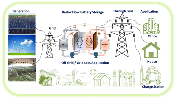
Recently, iron-based RFBs have emerged as an interesting candidate for long-term electrochemical storage due to their multivalent nature (Fe0, Fe2+, and Fe3+), good reversibility of Fe3+/Fe2+ (+0.77 V vs. SHE, theoretical capacity of 450 mA h g−1) and Fe2+/Fe (−0.44 V vs. SHE, theoretical capacity of 960 mA h g−1), eco-friendliness, and low elemental cost.30 The aforementioned features of iron have been considered to be of substantial interest in iron-based RFBs.29 Due to good reversibility and high redox potential of Fe2+/Fe3+ redox reaction, the Fe2+/Fe3+ has been used as a catholyte in various RFBs including Zn–Fe, Fe–Mn, Fe–S, etc.31 Zn–Fe RFB also investigated largely due to its high practical energy density at low cost. These benefits make Zn-iron-based RFBs a perfect choice for use in large-scale energy storage for off-grid applications. A schematic representation of the various applications of Zn–Fe RFBs is shown in Fig. 1. However, the hydrolysis of F(III), ion crossover, low solubility, and Zn dendrite formation are the major concerns. To overcome this, various approaches have been considered regarding Zn–Fe in recent times. Therefore, this review is exclusively focused on the recent development of Zn–Fe-based RFBs along with their future perspectives.
2.1. Electrochemistry of the zinc redox couple
Zn(OH)42− + 2e− ![[left over right harpoons]](https://www.rsc.org/images/entities/char_21cb.gif) Zn + 4OH− E° = −1.26 V vs. SHE Zn + 4OH− E° = −1.26 V vs. SHE
| (2) |
Zn2+ + 2e− ![[left over right harpoons]](https://www.rsc.org/images/entities/char_21cb.gif) Zn E° = −0.76 V vs. SHE Zn E° = −0.76 V vs. SHE | (3) |
Zinc ions (Zn2+) undergo three stages, similar to that in alkaline medium, but there is no pre-transformation step since zincate ions are absent in the electrolyte. The Zn2+ ions are immediately reduced at the electrode surface, resulting in the nucleation process.
It can be seen that zinc exhibits a very low redox potential of −1.22 V vs. SHE in an alkaline medium which would be more beneficial for a battery to achieve high voltage when paired with high redox potential couples.32,33 Alkaline medium often has better electrolyte conductivity than neutral medium, resulting in a faster transfer of OH− than K+ or Na+. Therefore, alkaline zinc-based RFBs can operate at a high current rate, and as a result, high power densities can be achieved.
2.2. Electrochemistry of the iron redox couple
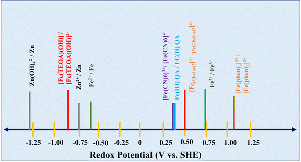
Iron electrodes/electrolytes offer safety and environmental advantages when compared to other battery electrode/electrolyte materials such as nickel, cadmium, lead, and zinc, which are very harmful. As mentioned, the cell potential of the redox flow battery is highly dependent on the combination of the positive and negative redox couples. A schematic representation of the redox potential of Zn–Fe under various conditions is shown in Fig. 2.Fe(OH)2 + 2e− ![[left over right harpoons]](https://www.rsc.org/images/entities/char_21cb.gif) Fe + 2OH− E° = −0.87 V vs. Hg/HgO Fe + 2OH− E° = −0.87 V vs. Hg/HgO | (4) |
The discharge product, iron(II) hydroxide, is oxidized to iron(III) hydroxide. Upon further discharge, it undergoes the reaction shown below:
Fe(OH)3 + e− ![[left over right harpoons]](https://www.rsc.org/images/entities/char_21cb.gif) Fe(OH)2 + OH− E° = −0.56 V vs. Hg/HgO Fe(OH)2 + OH− E° = −0.56 V vs. Hg/HgO | (5) |
The reaction in eqn (5) takes place at a very low cell voltage and so cannot be used to store energy. The conversion of iron(II) hydroxide to iron involves a plating/stripping mechanism.34 During discharge, iron is oxidized to produce the ferrite anion as shown in eqn (6). The resultant ferrite anion is very slightly soluble in an alkaline medium and it further hydrolyzes to form iron(II) hydroxide as shown in eqn (7):
Fe + 3OH− ![[left over right harpoons]](https://www.rsc.org/images/entities/char_21cb.gif) HFeO2− + H2O + 2e− HFeO2− + H2O + 2e− | (6) |
HFeO2− + H2O ![[left over right harpoons]](https://www.rsc.org/images/entities/char_21cb.gif) Fe(OH)2 + OH− Fe(OH)2 + OH− | (7) |
Iron(II) hydroxide is electrically insulating and gets passivated on the electrode surface at high current densities; thus, it is necessary to prevent the electrode from being completely discharged. As Fe(OH)2 is thermodynamically unstable, it forms iron oxide as shown in eqn (8):
| 3Fe(OH)2 → Fe3O4 + 2H2O + H2 | (8) |
Fe2+ + 2e− ![[left over right harpoons]](https://www.rsc.org/images/entities/char_21cb.gif) Fe E° = −0.44 V vs. SHE Fe E° = −0.44 V vs. SHE | (9) |
2H+ + 2e− ![[left over right harpoons]](https://www.rsc.org/images/entities/char_21cb.gif) H2 E° = −0.32 V vs. SHE H2 E° = −0.32 V vs. SHE | (10) |
On the other hand, aqueous Fe3+/Fe2+ is one of the safest, low-cost, and widely used redox couples for positive electrode reactions with high reversibility even upon comparison with unmodified carbon electrodes.35 The electrochemical process of the Fe3+/Fe2+ redox couple is shown below:
Fe3+ + e− ![[left over right harpoons]](https://www.rsc.org/images/entities/char_21cb.gif) Fe2+ E° = +0.77 V vs. SHE Fe2+ E° = +0.77 V vs. SHE | (11) |
Though the Fe3+/Fe2+ redox couple is useful in energy storage, it cannot withstand high pH conditions due to precipitation as ferric hydroxide caused by HER at the anode. So, the pH of the electrolyte has to be carefully maintained throughout the battery operations. Further, Fe3+ ions have a greater tendency to crossover from the positive to negative side compartment which causes self-discharge. Thus, coordinating ferric ions with suitable ligands can mitigate this situation.36–38
2.3. Working principle of the zinc–iron redox flow battery
Zinc electrodeposition occurs via distinct mechanisms in alkaline and neutral/acidic environments. A schematic representation of the Zn–Fe redox flow cell is shown in Fig. 3.It is critical to develop a novel flow battery technology with low cost, high energy density, and superior electrochemical activity. In this regard, zinc and iron are two widely available metals found in the earth's crust, which also exhibit excellent electrochemical characteristics. The high solubility of zinc and iron salts makes it easy to construct the battery to achieve high energy density. Further, zinc plating/stripping is relatively more stable than iron plating/stripping, so using zinc as the anode is highly beneficial over iron as it controls HER, enables fast kinetics with high coulombic efficiency, and exhibits low redox potential. The half-cell reactions for zinc–iron RFBs occur at the anode and cathode and are represented in eqn (12) and (13):
At the anode:
Zn2+ + 2e− ![[left over right harpoons]](https://www.rsc.org/images/entities/char_21cb.gif) Zn E° = −0.76 V vs. SHE Zn E° = −0.76 V vs. SHE | (12) |
At the cathode:
2Fe2+ ![[left over right harpoons]](https://www.rsc.org/images/entities/char_21cb.gif) 2Fe3+ + 2e− E° = +0.77 V vs. SHE 2Fe3+ + 2e− E° = +0.77 V vs. SHE | (13) |
Net cell reaction:
Zn2+ + 2Fe2+ ![[left over right harpoons]](https://www.rsc.org/images/entities/char_21cb.gif) Zn + 2Fe3+ Ecell = +1.53 V Zn + 2Fe3+ Ecell = +1.53 V | (14) |
During the charging process, Fe2+ ions are oxidized to form Fe3+ ions at the positive electrode, whereas Zn2+ ions at the negative electrode receive these electrons from the external circuit and get electrodeposited as metallic Zn on the electrode. During the discharge process, reverse reactions occur at the corresponding electrodes. Since the zinc anode involves a plating/stripping mechanism, it cannot decouple its energy and power density independently. Hence, a hybrid redox flow battery is considered. Further, the zinc–iron flow battery has various benefits over the cutting-edge all-vanadium redox flow battery (AVRFB), which are as follows: (i) the zinc–iron RFBs can achieve high cell voltage up to 1.8 V which enables them to attain high energy density, (ii) since the redox couples such as Zn2+/Zn and Fe3+/Fe2+ show fast redox kinetics with high cell voltage, it is possible to test at high current density operations. So far, 260 mA cm−2 is the maximum operable current density,39 and (iii) alkaline zinc–iron RFBs can attain a capital cost of less than $90 per kW h.40
3. Challenges in Zn–Fe redox flow batteries
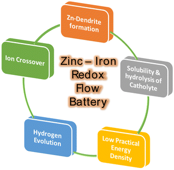
Various common issues such as low power density, low practical energy density, solubility and ion crossover between the compartments during cell operations have been identified in any RFB system. Zn-based RFBs also have similar issues along with Zn dendrite formation during the cell operation (Fig. 4). The major issues have to be addressed to obtain good-performing Zn–Fe RFBs are mention in Fig. 4.(a) Zinc anode-dendrite formation
The complications related to the zinc redox couple originate mostly from zinc dendrite and residual zinc deposits during cell operations which constitute one of the most vital concerns for zinc-based RFBs. The zinc dendrite/residual zinc deposits are more problematic in an alkaline medium than in a neutral or acidic medium, particularly at high current densities (>60 mA cm−2). During the charging process, zinc ions get electroplated on the electrode, and not all the plated zinc gets stripped off, and some zinc deposits remain intact in the electrode itself known as residual zinc, which affects the capacity of a battery and triggers inhomogeneous zinc plating followed by dendrite formation (Fig. 5). Another major concern with the zinc anode is the restricted areal capacity and limited operating current density which have been evaluated from several viewpoints in recent years.41,42(b) Membrane–ion transfer
An ideal membrane for RFBs should have good ionic conductivity, selectivity for ions, and great stability to provide a long lifespan. One of the most critical characteristics of membranes used in zinc–iron RFBs is their stability in alkaline medium, as most often a highly concentrated alkaline solution (3 M KOH or NaOH) is used for zinc–iron RFBs. As a result, the hydrocarbon polymer backbone and the anion-exchange group can be deteriorated. Furthermore, the Nafion series membranes have various disadvantages compared to the aforementioned alternative hydrocarbon-based membranes such as high cost and low conductivity in alkaline-based flow batteries.42,43 Further, the selection of the IEM or separator is very important to avoid the various issues related to the Zn–Fe cell operations (Fig. 6).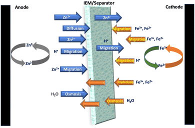 | ||
| Fig. 6 Schematic representation of the transfer of various ions and molecules through the separators during the cell operation of the Zn–Fe system. | ||
(c) Low solubility and hydrolysis of iron at the cathode
The poor solubility of the ferro-ferricyanide redox couple in a positive electrolyte results in low energy density.44 Changing the counter ions (K+ or Na+) of ferro-ferricyanide ions to ammonium ions is an effective technique for increasing the concentration of the ferro-ferricyanide pair in aqueous solution. However, the instability of ammonium ions in high alkaline media makes it problematic to use them in alkaline-based RFBs. The ferro-ferricyanide redox couple concentration in an alkaline medium is 0.4 M, significantly lower than the concentration of vanadium ions (1.5 M) in a vanadium flow battery.39,40 On the other hand, ferric ions (Fe3+) in the positive electrolyte (i.e., catholyte) are highly unstable at pH > 4.5 and form ferric hydroxide (Fe(OH)3) as shown in eqn (15)–(17) and get precipitated:26| Fe3+ + H2O → Fe(OH)2+ + H+ | (15) |
| Fe(OH)2+ + H2O ↔ Fe(OH)2+ + H+ | (16) |
| Fe(OH)2+ + H2O ↔ Fe(OH)3 + H+ | (17) |
Further, Fe3+ ions have a greater tendency to crossover from the positive side to the negative side and initiate self-discharge of the battery.45 Therefore, urgent steps must be taken to mitigate the aforementioned issues.
(d) Water transfer through the membrane/separator
The irreversible water transfer is another issue widely seen in RFBs. The differences in the concentration gradient and ionic strength will arise between the positive and negative electrolytes, causing the battery to suffer from water transfer. This problem might reduce the battery performance significantly causing scarcity/imbalance of electrolytes. Thus, adding additives to negative electrolytes or optimizing electrolyte ingredients to balance the disproportion in the concentration gradient and ionic strength in electrolytes are viable approaches to solve the problem of water transport.46,47(e) Hydrogen evolution reaction (HER)
Hydrogen generation is one of the major concerns in RFBs. The parasitic HER reduces the capacity of the RFBs. Primary electrodes in the negative compartment (graphite or carbon felt) are subjected to thermal treatments to suppress the HER. Further, the H2 gas molecule formation at the anode compartment restricts the electrolyte flow which increases the pressure inside the cell. Thus, it will increase the overall cell resistance and leakage of the electrolyte, and hence, the cell performance will be strictly affected. Much attention is needed regarding the negative electrode electrolyte compartment to overcome this HER issue.4. Progress of Zn–Fe redox flow batteries
As previously stated, techniques for exploring advanced materials, i.e., electrodes, electrolytes, and separators, are critical for mitigating the concerns and challenges connected with Zn–Fe RFBs, as the essential materials of RFBs ultimately decide the battery performance. The key requirements for any RFB are given in Fig. 7.4.1. Electrodes
The electrode is a key component in RFBs; it provides an active area for the redox reactions to occur, but it does not take part in the reaction. The physicochemical characteristics of the electrode greatly influence the battery performance.48,49The effects of zinc plates and carbon felt (CF) as electrodes in alkaline zinc–iron RFBs were investigated.40 Uneven zinc deposition and the formation of zinc dendrites due to poor electrical conduction between the zinc plate and deposited metallic zinc. As a result, the deposited metallic zinc gets peeled off during the discharge process, resulting in zinc electrode deformation and corrosion. On the other hand, uniform deposition of zinc occurs on the CF electrode due to the high adsorption ability of zinc and the large specific surface area of CF. This significantly reduces the internal interfacial resistance between the electrode and the deposited metallic Zn and promotes the diffusion of OH− ions due to the smooth nature of CF. Zn–Fe RFB with CF shows an EE of 84.05%, which is much greater than that of the Zn plate (78.52%). A transient 2D mathematical model has been explored for the porous electrode in an alkaline zinc–iron RFB. The alkaline zinc–iron RFB having a 7 mm thick anode and a 10 mm thick cathode with a porosity of 98% exhibited energy, coulombic energy, and utilization rates of 92.84, 99.18, and 98.62%, respectively.50 Thus, thick, highly smooth and porous electrodes greatly enhanced the battery performance. Similarly, Beck et al.51 used a 3D model of a porous electrode to create architecture electrodes that reduced power loss more than bulk electrodes due to porosity distribution optimization. The power efficiency of the framework scaling from 4 cm2 to 64 cm2 was lowered by 12.3% when using the variable porosity electrode, but by 40.3% when utilizing the uniform porosity electrode.
4.2. Membranes
Various types of membranes have been employed in energy storage applications. The membrane or separator can be classified based on the working mechanism or nature of the physical and chemical characteristics. The separators can be woven, non-woven, molded sheets, ribbed-type porous membranes, etc. Based on the pore size, the separator or membrane is classified as (1) microporous (50–100 Å), (2) non-woven (1–100 μm) and (3) ion-exchange membrane (>20 Å).52 The selection of membranes or separators highly depends on the redox chemistry and the pH of the electrolyte combinations used in the battery.The ion-exchange membrane (IEM) or separator in RFBs is a very essential for separating positive and negative electrolytes which also helps in charge-balancing by exchanging ions between the electrolytes in some special cases where IEMs are employed.53 The ideal membrane or separator should have high ionic conductivity to reduce battery resistance, high ion selectivity to avoid self-discharge, chemical tolerance to withstand the highly alkaline environment, and high mechanical stability to protect the membrane from zinc dendrite damage. In zinc–iron RFBs, Zn2+ (anolyte) and Fe2+/Fe3+ (Fen+) (catholyte) ions are active redox couples shuttling between the membranes causing a capacity fade. It should be noted that the radius of Fen+ is 63–92 pm, which is much less than that of Zn2+ (139 pm). The Fen+ ion permeability through Nafion was found to be 5.5 × 10⁻⁵ cm2 min−1, which was 18.9–20.7 times greater than that of the vanadium ion (2.9 × 10⁻⁶ cm2 min−1).26 Hence, Fen+ crossovers are far easier than Zn2+ crossovers resulting in self-discharge of the battery. The selection of membrane materials with special designs in the cell architecture can enable the battery to show good performance.
![[thin space (1/6-em)]](https://www.rsc.org/images/entities/char_2009.gif) 500 cycles.58–60 In this connection, Yuan et al.40 demonstrated a low-cost PBI membrane in an alkaline zinc–iron RFB with a CE of 99.5% and an EE of 82.8% at 160 mA cm−2 that can withstand over 500 cycles. The feasibility of this battery is demonstrated by manufacturing a kilowatt cell stack with a capital cost of less than $90 per kW h. Moreover, the use of porous ion-conducting membranes instead of conventional IEMs reduces the problem of internal resistance of the membrane due to facile ion transport, which greatly improves the performance and stability of Zn–Fe RFBs. Remarkably, the cost-effective porous separator utilization can decrease the cost of zinc–iron RFBs to less than $50 per kW h. Recently, a microporous separator (Daramic 175, thickness 175 μm) was employed to separate the anode and cathode compartment of the flow cell.61 Yuan et al.62 created a nanoporous separator with negative charges in the pore surface and wall. The separator induces the deposition of zincate ions at the carbon felt framework by mutual repulsion between the separator's pore surface/walls and the zincate ions Zn(OH)42−. As a result, even if zinc dendrites emerge, they grow through the rear end of the separator, avoiding separator breakage and the zinc–iron RFB short-circuit phenomena. The use of a negatively charged nanoporous membrane results in no zinc dendrites at 80–160 mA cm−2 after 240 cycles. Further, to increase the conductivity of the membrane, a cation on the pristine SPEEK membrane wherein H+ is changed to K+ and used in zinc–iron RFB application. Though the main focus is on the SPEEK membrane, the flow cell is also tested using Nafion 117 and its performance is compared with the SPEEK-K-based Zn–Fe flow cell performance. The discharge capacity of the cell for the SPEEK-K membrane-based cell is much better (16.4% higher) than the Nafion 117-based cell configuration. However, the cell was tested up to only about 30 cycles.63 Minghui Yang et al.64 have elaborated on the performance using KBr as a supporting electrolyte where the Nafion 212 membrane is modified by exchanging the cation from H+ to K+ by soaking in 1 M KOH for about 1 h at 80 °C. The K+ exchange Nafion 212 membrane was employed and the cell was tested up to 2000 cycles, and it showed stable performance with a CE of nearly 100% at a capacitance retention of >80%. A similar ion exchange process was followed where Na+ was attached and the treatment was carried out in NaOH solution and used in the Zn–Fe flow cell investigation.65 On the other hand, Nafion 212 was used in the flow cell and the cell was tested up to 100 cycles.66 The use of condensing guanidine carbonate with formaldehyde followed by cross-condensation with melamine AEM allowing only the Cl− exchange from the anolyte to the catholyte showed no dendrites during the charging process. On the other hand, the porous PVC membrane-based cell showed dendrite formation even from the first cycle.67 It was observed that the ion-selective ability of the AEM membrane highly influences the uniform deposition of zinc on the anode during the charging process.62,68,69 The positive and negative half-cells were separated by a perfluorinated sulfonic acid membrane (Liaoning Keking New Materials, China) to prevent the ion crossover.70 Chen et al.71 used the crosslinked and methylated polybenzimidazole (PBI) anion exchange membrane (∼40 μm thick) and the developed flow cell showed 100% CE and was tested up to 150 cycles. However, the cell was tested at a maximum current density of 20 mA cm−2 only.
500 cycles.58–60 In this connection, Yuan et al.40 demonstrated a low-cost PBI membrane in an alkaline zinc–iron RFB with a CE of 99.5% and an EE of 82.8% at 160 mA cm−2 that can withstand over 500 cycles. The feasibility of this battery is demonstrated by manufacturing a kilowatt cell stack with a capital cost of less than $90 per kW h. Moreover, the use of porous ion-conducting membranes instead of conventional IEMs reduces the problem of internal resistance of the membrane due to facile ion transport, which greatly improves the performance and stability of Zn–Fe RFBs. Remarkably, the cost-effective porous separator utilization can decrease the cost of zinc–iron RFBs to less than $50 per kW h. Recently, a microporous separator (Daramic 175, thickness 175 μm) was employed to separate the anode and cathode compartment of the flow cell.61 Yuan et al.62 created a nanoporous separator with negative charges in the pore surface and wall. The separator induces the deposition of zincate ions at the carbon felt framework by mutual repulsion between the separator's pore surface/walls and the zincate ions Zn(OH)42−. As a result, even if zinc dendrites emerge, they grow through the rear end of the separator, avoiding separator breakage and the zinc–iron RFB short-circuit phenomena. The use of a negatively charged nanoporous membrane results in no zinc dendrites at 80–160 mA cm−2 after 240 cycles. Further, to increase the conductivity of the membrane, a cation on the pristine SPEEK membrane wherein H+ is changed to K+ and used in zinc–iron RFB application. Though the main focus is on the SPEEK membrane, the flow cell is also tested using Nafion 117 and its performance is compared with the SPEEK-K-based Zn–Fe flow cell performance. The discharge capacity of the cell for the SPEEK-K membrane-based cell is much better (16.4% higher) than the Nafion 117-based cell configuration. However, the cell was tested up to only about 30 cycles.63 Minghui Yang et al.64 have elaborated on the performance using KBr as a supporting electrolyte where the Nafion 212 membrane is modified by exchanging the cation from H+ to K+ by soaking in 1 M KOH for about 1 h at 80 °C. The K+ exchange Nafion 212 membrane was employed and the cell was tested up to 2000 cycles, and it showed stable performance with a CE of nearly 100% at a capacitance retention of >80%. A similar ion exchange process was followed where Na+ was attached and the treatment was carried out in NaOH solution and used in the Zn–Fe flow cell investigation.65 On the other hand, Nafion 212 was used in the flow cell and the cell was tested up to 100 cycles.66 The use of condensing guanidine carbonate with formaldehyde followed by cross-condensation with melamine AEM allowing only the Cl− exchange from the anolyte to the catholyte showed no dendrites during the charging process. On the other hand, the porous PVC membrane-based cell showed dendrite formation even from the first cycle.67 It was observed that the ion-selective ability of the AEM membrane highly influences the uniform deposition of zinc on the anode during the charging process.62,68,69 The positive and negative half-cells were separated by a perfluorinated sulfonic acid membrane (Liaoning Keking New Materials, China) to prevent the ion crossover.70 Chen et al.71 used the crosslinked and methylated polybenzimidazole (PBI) anion exchange membrane (∼40 μm thick) and the developed flow cell showed 100% CE and was tested up to 150 cycles. However, the cell was tested at a maximum current density of 20 mA cm−2 only.
A non-ionic ion-exchange membrane (n-IEM) has been employed to separate the anode and cathode compartment in which the alkaline electrolyte has been employed. The poly(ether sulfone) (PES) based membrane with high ion conductivity and anti-alkali stability was prepared and used for the alkaline Zn–Fe RFB where polyethylene glycol (PEG) was used as an additive. The non-ionic membrane based flow cell was tested at 80 mA cm−2 for about 120 cycles in an alkaline memdium.72 These findings confirm that the n-IEM has the potential for use in alkaline RFBs. Similarly, the microporous celgard membrane and Nafion 115 cation exchange membranes were investigated in the zinc–iron flow cell. The results obtained revealed much better performance while using the Nafion 115 membrane while the cell showed very poor performance when employing the microporous separator. The flow cell showed a CE of >90% and a VE of >86% over 20 cycles, and the cell showed a capacity retention of 80% after 200 cycles when using the Nafion 115 membrane.73
4.3. Electrolyte
As mentioned earlier, in conventional batteries, energy is stored in the electrodes whereas in RFBs the rated energy is determined by the electrolytes. The solubility of the redox active species and the redox potential of the electrolytes determine the capacity and efficiency of the system. Further, the pH of the electrolyte also plays a vital role in determining the cell voltage, as it alters the electrode potential. For instance, the Zn/Zn2+ redox reaction in a neutral electrolyte medium occurs at −0.76 V vs. SHE, whereas it occurs at −1.245 V vs. SHE in an alkaline medium. In the catholyte side, the positive redox couple of Fe3+/Fe2+ occurs at +0.744 V vs. SHE. Therefore, the combination of Zn/Zn2+ and Fe3+/Fe2+ as the anolyte and catholyte establishes a cell voltage of 1.52 V and 2 V in neutral and alkaline electrolyte medium, respectively. In a zinc–iron RFB system, the electrolytes at different pH have been employed; specifically, the alkaline-based anolyte has attracted much attention due to the high reduction potential of Zn/Zn2+. On the other hand, neutral electrolytes preferred the additives on the catholyte side. A sharp increase in the charge potential was observed resulting in the irreversible HER in the negative half-cell. The HER results from the corrosion of zinc in alkaline solutions. The corrosion of zinc is the main cause of the self-discharge of secondary alkaline zinc-based batteries. To suppress the HER at the anode, many organic and inorganic additives have been employed; on the other hand, the addition of the additives also helps to balance the water transport between the half-cells. Systems of organic additives have been largely investigated under different conditions and have shown highly improved performance. The CV curve recorded at 20 mV s−1, potential, the peak current density, and peak current ratio are shown in Fig. 8(a–d).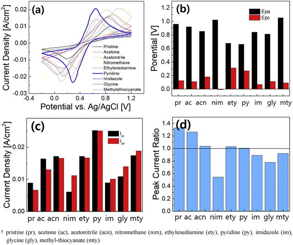 | ||
| Fig. 8 Electrochemical performance comparison of Fe(II) complexing ligands by CV measurements for 20 cycles at a scan rate of 30 mV s−1: (a) CV curves (the average), (b) anodic and cathodic peak potentials (Epa, Epc), (c) anodic and cathodic peak currents (Ipa, Ipc), and (d) peak current ratio [reproduced with permission66]. | ||
The Zn–Fe RFB showed 1.8 V cell voltage when designed using the triple-electrolyte combinations. The redox behavior of iron species has been tested in aqueous ionic liquid solutions. 1-Butyl-3-methylimidazolium chloride (BMImCl) is found to be the most effective in regulating the redox activity of iron species. In an anolyte, the standard rate constant of zinc plating/stripping was increased to 1.44 × 10⁻⁴ cm s−1 when aqueous 1 M NH4Cl was used as a supporting electrolyte; the flow cell exhibited a highly stable cycle over 150 cycles with an energy efficiency of 80% at 20 mA cm−2 in BMImCl/H2O in HCl and CaCl2/H2O in NH4Cl (0.5 M), as the anolyte and catholyte respectively.71 An alkaline Zn–Fe RFB was developed in which 1.0 mol L−1 Na4Fe(CN)6 in 3 mol L−1 KOH and 0.5 mol L−1 Zn(OH)42− in 4 mol L−1 NaOH were employed as catholyte and anolyte electrolytes, respectively. The high alkaline nature of the electrolyte helps smooth zinc stripping/plating which effectively suppresses zinc dendrite formation at the anode. Thus, this battery demonstrated a coulombic efficiency of 99.5% and an energy efficiency of 82.8%, and the cell was tested at 160 mA cm−2. The RFB was tested up to 500 cycles with a cell voltage of 1.74 V.40
With the beneficial fast redox kinetics of the Zn(OH)42−/Zn and Fe(CN)63−/Fe(CN)64− couples in an alkaline medium, the battery displayed no signs of activation polarization. Here, KBr was used as a supporting electrolyte on both sides. The combination of electrolytes showed cell performance over 2000 cycles without any noticeable capacity loss at 30 mA cm−2. Further, a stack having three cells was fabricated and the cell life was recorded up to 600 cycles.64 0.8 mol L−1 Na4Fe(CN)6 in 3 M mol L−1 KOH solution and 0.8 mol L−1 Na2Zn (OH)4 in 4 mol L−1 NaOH solution as positive and negative electrolytes, respectively used in the flow cell testing. The cell was tested at a maximum current density of 180 mA cm−2. The cycle performance was analyzed at 80 mA cm−2. The RFB demonstrated up to 150 cycles delivering a CE of 98.53% and a mean EE of 83.15%. The cell also showed stable performance up to 100 cycles even at 160 mA cm−2.72 K4Fe(CN)6 is identified as a highly suitable active electrolyte component in the positive electrolyte. However, the solubility of K4Fe(CN)6 in alkaline electrolytes is limited due to the common ion effect. The solubility of K4Fe(CN)6 was increased by employing a diverse ion effect. Therefore, to increase the solubility, NaOH was employed as a solvent. Higher solubility of 1.6 M K4Fe(CN)6 in 0.5 M NaOH was obtained promoting the high reversibility of Fe(CN)64−/Fe(CN)63−. A highly concentrated catholyte solution [1.46 M Fe(CN)64− from a mixture of 1.15 M K4Fe(CN)6 and 1.15 M Na4Fe(CN)6 in 0.5 M NaOH] was employed as the catholyte. The flow cell then showed maximum capacity retention of 98.51% with CE, VE, and EE of 100%, 83.43%, and 83.37% even after 124 cycles when tested at 100 mA cm−2. A maximum power density of 656.81 m W cm−2 was obtained at 1.0 M K3Fe(CN)6 in 1.0 M NaOH. Jeena et al.67 investigated a Zn–Fe RFB using 1 M Zn(II) chloride and the mixture of 0.5 M FeCl2 and 0.5 M FeCl3 with 2 M NH4Cl as the anolyte and catholyte, respectively. Here, NH4Cl was added to the positive electrolyte as a supporting electrolyte to improve the conductivity of the electrolyte. The cell delivered a maximum energy efficiency of 81% at 15 mA cm−2. However, the cycle life was tested only up to 32 cycles. The high reversibility of Zn was realized on carbon-felt electrodes for zinc–iron RFBs by introducing nicotinamide (NAM) as an additive to the neutral ZnCl2 anolyte. The addition of NAM not only enhances the Zn striping/plating reaction but also helps to improve power density (185 mW cm−2), enabling good cycle life stability (400 cycles) with the energy efficiency of the flow cell around 70% at 50 mA cm−2. Fig. 9 shows the cell performance under different conditions as investigated by Tang et al.70
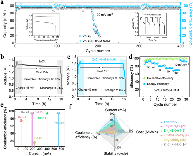 | ||
| Fig. 9 (a) Long-term cycling tests of the Zn–Fe RFB at 20 mA cm−2. (b) and (c) Long standby tests of the Zn–Fe RFB using pure ZnCl2 and ZnCl2–NAM. (d) Rate performance of the Zn–Fe RFB adopting a mixed ZnCl2 and NAM anolyte at 10–50 mA cm−2. (e) and (f) Comparison of the proposed Fe–Zn flow cell with other reported Zn-based RFBs [reproduced with permission from ref. 70]. | ||
To obtain a long cycle life and improved performance of the flow cell, pyridine was used as an Fe(II) complexing agent in the positive electrolyte. The pyridine ligand was coordinated with Fe2+ to improve the reversibility of the F2+/F3+ redox reaction. The pyridine -incorporated electrolyte system delivered excellent performance when compared with the pristine electrolyte. The cell delivered an energy efficiency of around 80% up to 100 cycles.66 On the other hand, 0.1 mol L−1 Zn(OH)42− + 1 mol L−1 OH− and 40 mL of 0.4 mol L−1 Fe(CN)64− + 1 mol L−1 OH− were employed as the anolyte and catholyte, respectively. Long-term cycle stability of the flow cell was recorded at 140 mA cm−2 up to 500 cycles. The flow cell delivered nearly 100% CE and about 80% of EE.74 The ZnCl2/Fe(bpy)3Cl2 based RFB delivered a CE > 90% and a voltage efficiency of >86% over 20 cycles and around 80% capacity retention was observed even after 200 cycles.73 The key performances of the Zn–Fe RFBs are compared in Table 1. Zhang et al.64 investigated the Zn–Fe RFB using FeCl2 in BMImCl with 1 M HCl as the catholyte and ZnCl2 in 3.5 M CaCl2 with 0.5 M NH4Cl as the anolyte. The addition of BMImCl/H2O in the anolyte has improved the reaction kinetics of Zn plating and striping reaction.71 It is believed that the addition of complexing additives will further improve cell performance where the additive should be electrochemically inactive to avoid any side reactions. The additive should be complexed with the main electrolyte component and chemically reversible during the cell operation.
| S. no. | Electrolyte | Separator | Efficiency (%) | Cycle life | Ref. | |
|---|---|---|---|---|---|---|
| Anolyte | Catholyte | |||||
| 01. | 0.6 M FeCl2 + 0.5 M NaCl + 1 M HCl | 0.3 M Na2[Zn(OH)4] + 0.5 M NaCl + 2.4 M NaOH | Nafion-212 and FAA3 | 99.9 (CE), 76 (VE) at 80 mA cm−2 | 20 cell stack | 54 |
| Middle electrolyte: 3 M NaCl | ||||||
| 02. | 1 M ZnBr2 + 2 M KCl | 2 M FeCl2 + 4 M glycine + 2 M KCl | Polybenzimidazole porous membrane | 97.75 (CE), 86.66 (EE) at 40 mA cm−2 | 100 | 75 |
| 03. | 0.1 M ZnBr2 + 2 M KCl | 0.2 M FeCl2 + 0.4 M glycine + 2 M KCl | SPEEK-K type membrane | 95 (CE), 78 (EE) at 40 mA cm−2 | 30 | 63 |
| 04. | 0.1 M ZnBr2 + 4.0 M KBr | 0.1 M K3Fe(CN)6 + 3 M KBr | Nafion-212 | 99.9 (CE) at 30 mA cm−2 | 320 | 64 |
| 05. | 1.6 M ZnCl2 + 0.8 M FeCl2 + 2 M NH4Cl + 2 g PEG8000 | 1.6 M ZnCl2 + 0.56 M + FeCl2 + 0.24 M FeCl3 + 2 M NH4Cl + 2 g PEG8000 | Microporous separator (Daramic 175) | 85 (CE) | 125 | 61 |
| 06. | 0.5 M Zn(OH)42− + 4M NaOH | 1 L Na4Fe(CN)6 + 3 M KOH | Polybenzimidazole membrane | 99.5 (CE), 82.8 (EE) at 160 and 80 mA cm−2 | 500 | 40 |
| 07. | 1 M ZnCl2 | 0.5 M FeCl2 + 0.5 M FeCl3 + 2 M NH4Cl | Anion exchange membrane | 92 (CE), 85 (VE), ∼78 (EE) at 25 mA cm−2 | 30 | 67 |
| 08. | 0.5 M ZnCl2 + 0.05 M nicotinamide (NAM) + 3 M KCl | 0.5 M K4Fe(CN)6 + 1 M KCl | Perfluorinated sulfonic acid membrane | 70 (EE) at 50 mA cm−2 | 400@20 mA cm−2 | 70 |
| 09. | 1.6 M ZnCl2 | 0.8 M FeCl2 + 0.8 M pyridine | Nafion-212 membrane | 94.57 (CE), 81.26 (VE), 76.82 (EE) | 100 | 66 |
| 10. | 0.8 M Na2Zn(OH)4 + 4 M NaOH | 0.8 M Na4Fe(CN)6 + 3 M KOH | Non-ionic poly(ether sulfone) (PES) membrane and polyethylene glycol (PEG) as additive | 99 (CE), 87 (EE) at 80 mA cm−2 | 150 | 72 |
| 11. | 0.2 M ZnBr2 in 4.0 M NaOH | 0.1 M K4Fe(CN)6 in 1.0 M NaOH | Nafion-212 membrane | 88.10 (EE) at 100 mA cm−2 | 8000@100 mA cm−2 | 65 |
| 900@200 mA cm−2 | ||||||
| Cell stack | ||||||
| 12. | 0.1 M Zn(OH)42− + 1M OH− | 0.4 M Fe(CN)64− + 1M OH− | Montmorillonite-based separator | 80 (EE) at 140 mA cm−2 | 500@140 mA cm−2. | 74 |
| 13. | 0.1 M ZnCl2 + 2M NaCl | 0.1 M Fe(bpy)3Cl2 + 2 M NaCl | Nafion-115 | 86.19%@1 mA cm−2 | 20@1 mA cm−2 | 73 |
4.4. Zn–Fe stack performance
Zn–Fe RFBs have been demonstrated at the stack level due to their excellent optimized cell performance representing them as a major competitor in the commercial market soon. To ensure this low-cost, eco-friendly, Zn–Fe RFB system, stack cells under various conditions have been analyzed at different cell levels. A three-cell stack was fabricated and its electrochemical performance was recorded. Photograph of the flow cell stack and its cycle life performance are shown in Fig. 10a and b. With a stack voltage of 3.9 V, the cell stack showed a stable performance over 625 cycles with a CE of 99.0% at 30 mA cm−2.64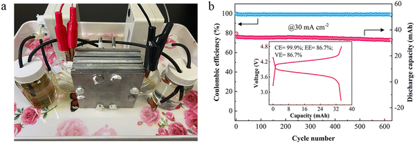 | ||
| Fig. 10 (a) A photograph of the neutral Zn/Fe RFB stack. (b) Cycling performance of the cell stack; the inset shows the 10th charging/discharging curve [reproduced with permission from ref. 64]. | ||
The practical viability of the alkaline Zn–Fe RFB was ensured by making ten cells stacked with the help of the self-made PBI membrane. The stacked cell was charged at 20 V and showed an average discharge voltage of 16.10 V when tested at a current density of 80 mA cm−2. The flow cell showed a CE, EE, and VE of 98.84%, 84.17%, and 85.16%, respectively, at a current density of 80 mA cm−2, with an output power of 1.127 kW.40 Photographs of the flow cell stack is shown in Fig. 11A. The GCD profile, continuous GCD cycle, and the efficiency vs. cycle life of the stack are shown in Fig. 11B–D.
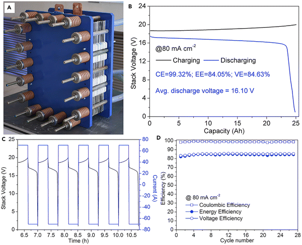 | ||
| Fig. 11 Practical realization of the alkaline zinc–iron flow battery: (A) the kW alkaline zinc–iron flow battery cell stack prototype using a self-made, low-cost non-fluorinated ion-exchange membrane. (B) Cell stack voltage profile of the alkaline zinc–iron flow battery at a current density of 80 mA cm−2. (C) Parts of charge and discharge curves of the cell stack. (D) Cycle performance of the cell stack at a current density of 80 mA cm−2 [reproduced with permission from ref. 40]. | ||
A cell stack was fabricated and its electrochemical performance was analyzed using an alkaline electrolyte. In the stack cells, a high concentration of catholyte was employed where 1 M NaOH was used as a solvent. The photograph of the flow cell stack and the capacity vs. voltage profile of the flow cell stack at the 10th and 100th cycles and the efficiency vs. cycle number are shown in Fig. 12(a–c).40
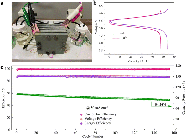 | ||
| Fig. 12 Practicability analysis of the AZIRFB system with high-concentration catholyte. (a) A photograph of the AZIRFB cell stack. (b) Selected charge–discharge voltage curves of the cell stack at 50 mA cm−2. (c) Cycling performance of the cell stack at 50 mA cm−2 [reproduced with permission from ref. 65]. | ||
4.5. Cost analysis comparison
Further, Tan et al.76 modeled the flow cell stack under various conditions. The modeled flow cell is also shown in Fig. 13. Thus, the low-cost Zn–Fe RFB will become a suitable replacement for the expensive all-vanadium redox flow battery. However, various challenges have to be addressed before bringing it into the commercial perspective.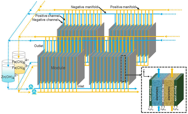 | ||
| Fig. 13 Schematic of a zinc–iron flow battery stack [reproduced with permission from ref. 76]. | ||
The capital cost of the Zn–Fe RFB was analyzed and compared with that of other redox flow batteries (Fig. 14). It was observed that among the other large-scale energy storage systems, the Zn–Fe RFB showed highly efficient overall capital cost ($ per kW h) at low current density.54
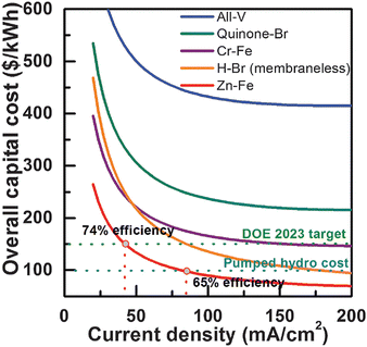 | ||
| Fig. 14 Zn–Fe RFB cost analysis and comparison with other notable RFBs. Note that long-term durability was not considered in the cost analysis in this work, and the cost comparison among different RFB technologies is only meaningful when they have the same or similar durability (reproduced with permission from ref. 54). | ||
5. Future perspectives
A constant and continuous effort is needed to improve the Zn–Fe RFB cell performances. An effort should be made on all the key aspects including electrode, electrolyte, cell design, and operating conditions. Since the energy is determined by the redox nature of the couples, special attention should be given to the investigation of the redox couples such as Zn2+/Zn and Fe3+/Fe2+.(i) Redox couple: to enhance the cell performance the redox couple environment has to be carefully evaluated. The pH of the electrolyte component plays a major role in the determination of the cell voltage of the redox flow battery. For instance, the Zn/Zn2+ redox reaction occurred at 0.76 V and 1.26 V in neutral and alkaline electrolyte medium. Due to the high electrode potential, an interest in the alkaline-based Zn electrolyte for redox flow battery has been largely increased in the past few years. However, the Zn dendrite is still being a major concern. To suppress the Zn dendrite, the electrode can be modified where a smooth Zn deposition is possible. The roughness of the electrode materials has to be controlled during the modification process. In most cases, the carbon felt is heated at a very high temperature, which creates more defects on the surfaces. This will strictly affect the cell performance; therefore, the defect formation should be controlled by limiting the activation process. The electrode conductivity is also very important to operate the cells at rated high current density. On the other hand, the electrolyte component can also be modified and additives can be incorporated to control the dendrite formation. To control and understand the formation of the Zn dendrite, advanced material characterization might be used to characterize the interfacial interactions, particularly at the negative electrodes.
(ii) Iron hydrolysis: to develop a good performing catholyte, it has to be subjected to severe analyses in terms of the electrode reaction mechanism under different pH and additive environmental conditions. For example, in the case of Fe3+/Fe2+, iron hydrolysis is a major issue. A detailed working mechanism using theoretical calculations has to be explored for an in-depth understanding of the side reactions. Additionally, in situ characterization techniques are required to evaluate the iron-complexation process in depth. The selection of solvent specifically in an alkaline electrolyte medium is very important. As discussed, the precursor or source material of Fe is very important for the better performance of the flow cell.
(iii) The supporting electrolytes play an vital role on the Zn–Fe redox flow batteries performances. Different organic and inorganic additives have been investigated so far in various RFB applications. As mentioned, the additives should have good conductivity and should be electrochemically inactive; at the same time, they should have good chemical reversibility to avoid a side reaction at the electrode.
(iv) The development of low-cost membranes is the most crucial part of achieving scalability for Zn–Fe RFBs. The study and development of membrane materials with strong mechanical properties and self-recovery capabilities is of high priority. Innovative polymers, through molecular design, are still required to provide high-performance membranes for zinc–iron RFB applications. The porosity has to be controlled for the porous membranes, and the stability of the IEMs should be improved to have good performance under the high-risk condition of the RFB.
(v) Molecular modeling of electrolyte components and separators (to obtain optimum porosity) is very important to obtain good-performing RFBs. Flow cell design is another important area where the width and depth of the flow fields play a very important role in the physical and mechanical aspects of the flow cell performance. The felt electrode thickness is another important factor where the pressure built in the cell compartment is carried by the 3D porous structure of the felt electrode. The key components may be optimized further using new artificial intelligence (AI) and machine learning tools. Along with the molecular modeling, DFT studies will further aid in understanding the effective electrolyte additive components.
(vi) Hydrogen evaluation is another important issue that has to be suppressed during the cell operation. To overcome this issue, the graphite composite plate may be prepared by having a few wt% of the additives which can suppress hydrogen evolution during the cell operation. The addition of additives or the catalyst with elements that can suppress HER such as Bi, Sn, Sb, Pb, etc. will improve the cell performance.
Thus, to meet the global energy demand, Zn–Fe redox flow batteries will be one of the highly suitable sustainable energy storage systems. However, their future development will be dependent on solving zinc dendrites and iron(III) hydrolysis, and finding robust membranes that fulfill the primary economic and technological criteria of cost, power density, efficiency, and durability of the RFBs.
Data availability
There is no data used in this review article.Conflicts of interest
The author declares no conflict of interest.Acknowledgements
Dr M. U. acknowledges the Amrita Vishwa Vidyapeetham “Seed Grant” Project (Proposal ID: ASG2022069) for providing financial support.References
- Y. Deng, Y. Wang, X. Xing, Y. Xiong, S. Xu and R. Wang, Requirement on the Capacity of Energy Storage to Meet the 2 °C Goal, Sustainability, 2024, 16(9), 3753 CrossRef.
- X. Tang, C. Zhu, Y. Yang, S. Qi, M. Cai, A. N. Alodhayb and J. Ma, Additive regulating Li+ solvation structure to construct dual LiF−rich electrode electrolyte interphases for sustaining 4.6 V Li||LiCoO2 batteries, Chin. Chem. Lett., 2024, 35(12), 110014 CrossRef CAS.
- C. Zhu, D. Wu, C. Wang and J. Ma, Flame-Retardant, Self-Purging, High-Voltage Electrolyte for Safe and Long-Cycling Sodium Metal Batteries, Adv. Funct. Mater., 2024, 2406764 CrossRef CAS.
- D. Wu, C. Zhu, H. Wang, J. Huang, G. Jiang, Y. Yang, G. Yang, D. Tang and J. Ma, Mechanically and Thermally Stable Cathode Electrolyte Interphase Enables High-temperature, High-voltage Li||LiCoO2 Batteries, Angew. Chem., Int. Ed., 2024, 63(7), e202315608 CrossRef CAS PubMed.
- E. Sánchez-Díez, E. Ventosa, M. Guarnieri, A. Trovò, C. Flox, R. Marcilla, F. Soavi, P. Mazur, E. Aranzabe and R. Ferret, Redox flow batteries: Status and perspective towards sustainable stationary energy storage, J. Power Sources, 2021, 481, 228804 CrossRef.
- P. Arévalo-Cid, P. Dias, A. Mendes and J. Azevedo, Redox flow batteries: a new frontier on energy storage, Sustainable Energy Fuels, 2021, 5(21), 5366–5419 RSC.
- A. Z. Weber, M. M. Mench, J. P. Meyers, P. N. Ross, J. T. Gostick and Q. Liu, Redox flow batteries: a review, J. Appl. Electrochem., 2011, 41(10), 1137–1164 CrossRef CAS.
- A. Ashok and A. Kumar, A comprehensive review of metal-based redox flow batteries: progress and perspectives, Green Chem. Lett. Rev., 2024, 17(1), 2302834 CrossRef.
- A. Aluko and A. Knight, A Review on Vanadium Redox Flow Battery Storage Systems for Large-Scale Power Systems Application, IEEE Access, 2023, 11, 13773–13793 Search PubMed.
- A. G. Olabi, M. A. Allam, M. A. Abdelkareem, T. D. Deepa, A. H. Alami, Q. Abbas, A. Alkhalidi and E. T. Sayed, Redox Flow Batteries: Recent Development in Main Components, Emerging Technologies, Diagnostic Techniques, Large-Scale Applications, and Challenges and Barriers, Batteries, 2023, 9(8), 409 CrossRef CAS.
- D. G. Kwabi, Y. Ji and M. J. Aziz, Electrolyte Lifetime in Aqueous Organic Redox Flow Batteries: A Critical Review, Chem. Rev., 2020, 120(14), 6467–6489 CrossRef CAS PubMed.
- Y. Liu, J. Zhang, S. Lu and Y. Xiang, Polyoxometalate-based electrolyte materials in redox flow batteries: Current trends and emerging opportunities, Mater. Rep.: Energy, 2022, 2(2), 100094 CAS.
- M. Ulaganathan, V. Aravindan, Q. Yan, S. Madhavi, M. Skyllas-Kazacos and T. M. Lim, Recent Advancements in All-Vanadium Redox Flow Batteries, Adv. Mater. Interfaces, 2016, 3(1), 1500309 CrossRef.
- S. Suresh, M. Ulaganathan, N. Venkatesan, P. Periasamy and P. Ragupathy, High performance zinc-bromine redox flow batteries: Role of various carbon felts and cell configurations, J. Energy Storage, 2018, 20, 134–139 CrossRef.
- M. Ulaganathan, S. Suresh, K. Mariyappan, P. Periasamy and R. Pitchai, New Zinc–Vanadium (Zn–V) Hybrid Redox Flow Battery: High-Voltage and Energy-Efficient Advanced Energy Storage System, ACS Sustainable Chem. Eng., 2019, 7(6), 6053–6060 CrossRef CAS.
- K. Amini and M. Pritzker, Voltage Loss Analysis of Zinc-Cerium Redox Flow Batteries. ECS Meeting Abstracts, 2020, (45), 3732 Search PubMed.
- X. Xie, F. Mushtaq, Q. Wang and W. A. Daoud, The Renaissance of the Zn-Ce Flow Battery: Dual-Membrane Configuration Enables Unprecedentedly High Efficiency, ACS Energy Lett., 2022, 7(10), 3484–3491 CrossRef CAS.
- X. Cao, S. Wang, X. Xue and A. Zn−Ce Redox Flow, Battery with Ethaline Deep Eutectic Solvent, ChemSusChem, 2021, 14(7), 1747–1755 CrossRef CAS PubMed.
- Z. Xu, Q. Fan, Y. Li, J. Wang and P. D. Lund, Review of zinc dendrite formation in zinc bromine redox flow battery, Renewable Sustainable Energy Rev., 2020, 127, 109838 CrossRef CAS.
- J.-N. Lee, E. Do, Y. Kim, J.-S. Yu and K. J. Kim, Development of titanium 3D mesh interlayer for enhancing the electrochemical performance of zinc–bromine flow battery, Sci. Rep., 2021, 11(1), 4508 CrossRef CAS PubMed.
- Y. Wang, Z. Niu, Q. Zheng, C. Zhang, J. Ye, G. Dai, Y. Zhao and X. Zhang, Zn-based eutectic mixture as anolyte for hybrid redox flow batteries, Sci. Rep., 2018, 8(1), 5740 CrossRef PubMed.
- J. Park, M. Kim, J. Choi, S. Lee, J. Kim, D. Han, H. Jang and M. Park, Recent Progress in High-voltage Aqueous Zinc-based Hybrid Redox Flow Batteries, Chem. – Asian J., 2023, 18(2), e202201052 CrossRef CAS PubMed.
- Q.-Y. Zhao, G.-Y. Yin, Y.-F. Liu, R.-R. Tang, X.-W. Wu and X.-X. Zeng, Recent advances in material chemistry for zinc enabled redox flow batteries, Carbon Neutralization, 2023, 2(1), 90–114 CrossRef CAS.
- N. Chen, W. Wang, Y. Ma, M. Chuai, X. Zheng, M. Wang, Y. Xu, Y. Yuan, J. Sun, K. Li, Y. Meng, C. Shen and W. Chen, Aqueous Zinc–Chlorine Battery Modulated by a MnO2 Redox Adsorbent, Small Methods, 2023, 2201553 Search PubMed.
- Z. Pei, Z. Zhu, D. Sun, J. Cai, A. Mosallanezhad, M. Chen and G. Wang, Review of the I−/I3− redox chemistry in Zn-iodine redox flow batteries, Mater. Res. Bull., 2021, 141, 111347 CrossRef CAS.
- H. Zhang, C. Sun and M. Ge, Review of the Research Status of Cost-Effective Zinc–Iron Redox Flow Batteries, Batteries, 2022, 8(11), 202 CrossRef.
- R. P. Naresh, K. Mariyappan, D. Dixon, M. Ulaganathan and P. Ragupathy, Investigations on New Electrolyte Composition and Modified Membrane for High Voltage Zinc−Manganese Hybrid Redox Flow Batteries, Batteries Supercaps, 2021, 4(9), 1464–1472 CrossRef CAS.
- R. Naresh, V. G. Pol and P. Ragupathy, Energy storage mechanism, advancement, challenges, and perspectives on vivid manganese redox couples, Energy Adv., 2023, 2(7), 948–964 RSC.
- X. Wu, A. Markir, Y. Xu, C. Zhang, D. P. Leonard, W. Shin and X. Ji, A Rechargeable Battery with an Iron Metal Anode, Adv. Funct. Mater., 2019, 29(20), 1900911 CrossRef.
- M. C. Tucker, D. Lambelet, M. Oueslati, B. Williams, W.-C. J. Wang and A. Z. Weber, Improved low-cost, non-hazardous, all-iron cell for the developing world, J. Power Sources, 2016, 332, 111–117 CrossRef CAS.
- R. Qiu, J. Y. Zheng, H. G. Cha, M. H. Jung, K. J. Lee and Y. S. Kang, One-dimensional ferromagnetic dendritic iron wire array growth by facile electrochemical deposition, Nanoscale, 2012, 4(5), 1565–1567 RSC.
- S. Deshmukh, R. Thamizhselvan, K. Mariyappan, M. Kathiresan, M. Ulaganathan and P. Ragupathy, Hybrid Aqueous Alkaline Zinc/TEMPO Flow Battery: A Sustainable High Voltage Green Energy Storage Device, J. Electrochem. Soc., 2023, 170(5), 050522 CrossRef CAS.
- R. Thamizhselvan, R. Naresh, R. Sekar, M. Ulaganathan, V. G. Pol and P. Ragupathy, Redox flow batteries: Pushing the cell voltage limits for sustainable energy storage, J. Energy Storage, 2023, 61, 106622 CrossRef.
- R. D. Armstrong and I. Baurhoo, The dissolution of iron in concentrated alkali. Journal of Electroanalytical Chemistry and Interfacial, Electrochemistry, 1972, 40(2), 325–338 CAS.
- K. L. Hawthorne, J. S. Wainright and R. F. Savinell, Studies of Iron-Ligand Complexes for an All-Iron Flow Battery Application, J. Electrochem. Soc., 2014, 161(10), A1662 CrossRef CAS.
- Y. W. D. Chen, K. S. V. Santhanam and A. J. Bard, Solution Redox Couples for Electrochemical Energy Storage: I. Iron (III)-Iron (II) Complexes with O-Phenanthroline and Related Ligands, J. Electrochem. Soc., 1981, 128(7), 1460 CrossRef CAS.
- Y. H. Wen, H. M. Zhang, P. Qian, H. T. Zhou, P. Zhao, B. L. Yi and Y. S. Yang, A study of the Fe(III)/Fe(II)–triethanolamine complex redox couple for redox flow battery application, Electrochim. Acta, 2006, 51(18), 3769–3775 CrossRef CAS.
- A. S. N. Murthy and T. Srivastava, Fe(III)/Fe(II)—ligand systems for use as negative half-cells in redox-flow cells, J. Power Sources, 1989, 27(2), 119–126 CrossRef CAS.
- J. Hu, C. Yuan, L. Zhi, H. Zhang, Z. Yuan and X. Li, In Situ Defect-Free Vertically Aligned Layered Double Hydroxide Composite Membrane for High Areal Capacity and Long-Cycle Zinc-Based Flow Battery, Adv. Funct. Mater., 2021, 31(31), 2102167 CrossRef CAS.
- Z. Yuan, Y. Duan, T. Liu, H. Zhang and X. Li, Toward a Low-Cost Alkaline Zinc-Iron Flow Battery with a Polybenzimidazole Custom Membrane for Stationary Energy Storage, iScience, 2018, 3, 40–49 CrossRef CAS.
- W. Lu, C. Zhang, H. Zhang and X. Li, Anode for Zinc-Based Batteries: Challenges, Strategies, and Prospects, ACS Energy Lett., 2021, 6(8), 2765–2785 CrossRef CAS.
- Q. Zhang, J. Luan, Y. Tang, X. Ji and H. Wang, Interfacial Design of Dendrite-Free Zinc Anodes for Aqueous Zinc-Ion Batteries, Angew. Chem., Int. Ed., 2020, 59(32), 13180–13191 CrossRef CAS PubMed.
- J. Zhang, G. Jiang, P. Xu, A. Ghorbani Kashkooli, M. Mousavi, A. Yu and Z. Chen, An all-aqueous redox flow battery with unprecedented energy density, Energy Environ. Sci., 2018, 11(8), 2010–2015 RSC.
- Y. Vetriselvam, G. S. Ramachandran, R. Naresh, K. Mariyappan, R. Pitchai and M. Ulaganathan, Improved electro-kinetics of new electrolyte composition for realizing high-performance zinc-bromine redox flow battery, Next Energy, 2024, 4, 100123 CrossRef.
- J. G. Ibanez, C. S. Choi and R. S. Becker, Aqueous Redox Transition Metal Complexes for Electrochemical Applications as a Function of pH, J. Electrochem. Soc., 1987, 134(12), 3083 CrossRef CAS.
- R. S. Kingsbury, K. Bruning, S. Zhu, S. Flotron, C. T. Miller and O. Coronell, Influence of Water Uptake, Charge, Manning Parameter, and Contact Angle on Water and Salt Transport in Commercial Ion Exchange Membranes, Ind. Eng. Chem. Res., 2019, 58(40), 18663–18674 CrossRef CAS.
- X. Liu, H. Zhang, Y. Duan, Z. Yuan and X. Li, Effect of Electrolyte Additives on the Water Transfer Behavior for Alkaline Zinc–Iron Flow Batteries, ACS Appl. Mater. Interfaces, 2020, 12(46), 51573–51580 CrossRef CAS PubMed.
- K. Mariyappan, P. Saravanakumar, R. Thamizhselvan, P. Ragupathy and M. Ulaganathan, In-situ N-rGO Scaffold @3D Graphite Felt for High Power Polyhalide Hybrid Redox Flow Battery, Adv. Mater. Technol., 2023, 8(3), 2200869 CrossRef CAS.
- M. Ulaganathan, K. Mariyappan, S. Suresh and P. Ragupathy, Graphene Quantum Dot beyond Electrocatalyst: An In Situ Electrolyte Catalyst towards Improved Reaction Kinetics of VO2 +/VO2+ Redox Couples, J. Electrochem. Soc., 2020, 167(14), 140540 CrossRef CAS.
- Z. Chen, W. Yu, Y. Liu, Y. Zeng, Q. He, P. Tan and M. Ni, Mathematical modeling and numerical analysis of alkaline zinc-iron flow batteries for energy storage applications, Chem. Eng. J., 2021, 405, 126684 CrossRef CAS.
- V. A. Beck, J. J. Wong, C. F. Jekel, D. A. Tortorelli, S. E. Baker, E. B. Duoss and M. A. Worsley, Computational design of microarchitected porous electrodes for redox flow batteries, J. Power Sources, 2021, 512, 230453 CrossRef CAS.
- P. Arora and Z. Zhang, Battery Separators, Chem. Rev., 2004, 104(10), 4419–4462 CrossRef CAS PubMed.
- M. Park, J. Ryu, W. Wang and J. Cho, Material design and engineering of next-generation flow-battery technologies. Nature Reviews, Materials, 2016, 2(1), 16080 Search PubMed.
- K. Gong, X. Ma, K. M. Conforti, K. J. Kuttler, J. B. Grunewald, K. L. Yeager, M. Z. Bazant, S. Gu and Y. Yan, A zinc–iron redox-flow battery under $100 per kW h of system capital cost, Energy Environ. Sci., 2015, 8(10), 2941–2945 RSC.
- K. Lin, R. Gómez-Bombarelli, E. S. Beh, L. Tong, Q. Chen, A. Valle, A. Aspuru-Guzik, M. J. Aziz and R. G. Gordon, A redox-flow battery with an alloxazine-based organic electrolyte, Nat. Energy, 2016, 1(9), 16102 CrossRef CAS.
- S. Chu, Y. Cui and N. Liu, The path towards sustainable energy, Nat. Mater., 2017, 16(1), 16–22 CrossRef PubMed.
- T. Liu, X. Wei, Z. Nie, V. Sprenkle, W. Wang and A. Total, Organic Aqueous Redox Flow Battery Employing a Low Cost and Sustainable Methyl Viologen Anolyte and 4-HO-TEMPO Catholyte. Advanced Energy, Materials, 2016, 6(3), 1501449 Search PubMed.
- X. L. Zhou, T. S. Zhao, L. An, L. Wei and C. Zhang, The use of polybenzimidazole membranes in vanadium redox flow batteries leading to increased coulombic efficiency and cycling performance, Electrochim. Acta, 2015, 153, 492–498 CrossRef CAS.
- Z. Yuan, Y. Duan, H. Zhang, X. Li, H. Zhang and I. Vankelecom, Advanced porous membranes with ultra-high selectivity and stability for vanadium flow batteries, Energy Environ. Sci., 2016, 9(2), 441–447 RSC.
- Y. Chen, P. Xiong, S. Xiao, Y. Zhu, S. Peng and G. He, Ion conductive mechanisms and redox flow battery applications of polybenzimidazole-based membranes, Energy Storage Mater., 2022, 45, 595–617 CrossRef.
- S. Selverston, R. F. Savinell and J. S. Wainright, Zinc-Iron Flow Batteries with Common Electrolyte, J. Electrochem. Soc., 2017, 164(6), A1069 CrossRef CAS.
- Z. Yuan, X. Liu, W. Xu, Y. Duan, H. Zhang and X. Li, Negatively charged nanoporous membrane for a dendrite-free alkaline zinc-based flow battery with long cycle life, Nat. Commun., 2018, 9(1), 3731 CrossRef PubMed.
- S. Chang, J. Ye, W. Zhou, C. Wu, M. Ding, Y. Long, Y. Cheng and C. Jia, A low-cost SPEEK-K type membrane for neutral aqueous zinc-iron redox flow battery, Surf. Coat. Technol., 2019, 358, 190–194 CrossRef CAS.
- M. Yang, Z. Xu, W. Xiang, H. Xu, M. Ding, L. Li, A. Tang, R. Gao, G. Zhou and C. Jia, High performance and long cycle life neutral zinc-iron flow batteries enabled by zinc-bromide complexation, Energy Storage Mater., 2022, 44, 433–440 CrossRef.
- G. Wang, H. Zou, Z. Xu, A. Tang, F. Zhong, X. Zhu, C. Qin, M. Ding, W. You and C. Jia, Unlocking the solubility limit of ferrocyanide for high energy density redox flow batteries, Mater. Today Energy, 2022, 28, 101061 CrossRef CAS.
- Y. Kim, D. Yun and J. Jeon, Performance improvement of aqueous zinc-iron flow batteries through organic ligand complexation of Fe(II)/Fe(III), Electrochim. Acta, 2020, 354, 136691 CrossRef CAS.
- C. B. Jeena, P. J. Elsa, P. P. Moly, K. J. Ambily and V. T. Joy, A dendrite free Zn-Fe hybrid redox flow battery for renewable energy storage, Energy Storage, 2022, 4(1), e275 CrossRef CAS.
- B.-S. Lee, S. Cui, X. Xing, H. Liu, X. Yue, V. Petrova, H.-D. Lim, R. Chen and P. Liu, Dendrite Suppression Membranes for Rechargeable Zinc Batteries, ACS Appl. Mater. Interfaces, 2018, 10(45), 38928–38935 CrossRef CAS PubMed.
- X. Hao, J. Hu, Z. Zhang, Y. Luo, H. Hou, G. Zou and X. Ji, Interfacial regulation of dendrite-free zinc anodes through a dynamic hydrophobic molecular membrane, J. Mater. Chem. A, 2021, 9(25), 14265–14269 RSC.
- J. Yang, H. Yan, H. Hao, Y. Song, Y. Li, Q. Liu and A. Tang, Synergetic Modulation on Solvation Structure and Electrode Interface Enables a Highly Reversible Zinc Anode for Zinc–Iron Flow Batteries, ACS Energy Lett., 2022, 7(7), 2331–2339 CrossRef CAS.
- Y. Zhang, D. Henkensmeier, S. Kim, R. Hempelmann and R. Chen, Enhanced reaction kinetics of an aqueous Zn–Fe hybrid flow battery by optimizing the supporting electrolytes, J. Energy Storage, 2019, 25, 100883 CrossRef.
- D. Chen, C. Kang, W. Duan, Z. Yuan and X. Li, A non-ionic membrane with high performance for alkaline zinc-iron flow battery, J. Membr. Sci., 2021, 618, 118585 CrossRef CAS.
- Z. Xie, L. Wei and S. Zhong, An aqueous ZnCl2/Fe(bpy)3Cl2 flow battery with mild electrolyte, Front. Mater. Sci., 2020, 14(4), 442–449 CrossRef.
- H. Chen, C. Kang, E. Shang, G. Liu, D. Chen and Z. Yuan, Montmorillonite-Based Separator Enables a Long-Life Alkaline Zinc–Iron Flow Battery, Ind. Eng. Chem. Res., 2023, 62(1), 676–684 CrossRef CAS.
- C. Xie, Y. Duan, W. Xu, H. Zhang and X. Li, A Low-Cost Neutral Zinc–Iron Flow Battery with High Energy Density for Stationary Energy Storage, Angew. Chem., Int. Ed., 2017, 56(47), 14953–14957 CrossRef CAS PubMed.
- Z. Chen, Y. Liu, W. Yu, Q. He, M. Ni, S. Yang, S. Zhang and P. Tan, Cost evaluation and sensitivity analysis of the alkaline zinc-iron flow battery system for large-scale energy storage applications, J. Energy Storage, 2021, 44, 103327 CrossRef.
| This journal is © The Royal Society of Chemistry 2024 |

