DOI:
10.1039/D4DT02532F
(Paper)
Dalton Trans., 2025,
54, 1913-1928
Study of multimodal light emissions from Pr3+/Yb3+ doped NaLa(MoO4)2 phosphors for optoelectronic devices and plant-growth applications†
Received
5th September 2024
, Accepted 5th December 2024
First published on 19th December 2024
Abstract
Recent advancements in materials design have driven the scientific community to explore phosphor materials for multifunctional applications. This study presents the multimodal light emission (downshifting – DS, quantum cutting – QC, and upconversion – UC) from Pr3+/Yb3+ activated NaLa(MoO4)2 phosphors for multifunctional applications. Under blue (449 nm) and NIR (980 nm) excitation, co-doped phosphors emit visible light through DS and UC processes caused by different f–f transitions of Pr3+ ions. Additionally, when the co-doped samples are excited with blue light, they emit a near-infrared (NIR) light band ranging from 900 to 1050 nm. This is caused by the f–f transition of Yb3+ resulting from energy transfer from a single Pr3+ ion to a pair of Yb3+ ions through the QC process. Concurrently, in-depth investigations were conducted to understand the concentration and thermal quenching mechanism. Firstly, the applicability of phosphors in optical thermometry using the luminescence intensity ratio (LIR) technique was explored, with the maximum relative sensitivity of 0.41% K−1 (448 K). A phosphor-coated LED (pc-LED) was constructed by coupling NaLa0.97Pr0.03(MoO4)2 with a blue LED chip (InGaN). Furthermore, based on the observed optical properties of the prepared phosphor, its application in improving the photovoltaic performance of solar cells and indoor plant applications is systematically discussed.
1. Introduction
In the current era of materials science, functional materials are continually explored to address the increasing human demands in areas such as energy, health, environment, indoor agriculture, and technology.1–5 Some of these materials, known as multifunctional materials, possess unique properties that enable us to extract multiple functions from them. Any multifunctional material that can be produced through a cost-effective and environment-friendly process brings certain additional advantages, such as scalability, enhanced sustainability and reduced production cost. The advancement in the development of phosphors for multifunctional applications like solid-state lighting, luminescent solar concentrators (LSC), and luminescent thermometers using various luminescence phenomena such as downconversion (DC), quantum cutting (QC), and upconversion (UC) is highly beneficial.6–9 Lanthanide (Ln) doped molybdate phosphors have garnered significant attention for the aforementioned multifunctional applications due to their high luminescence efficiency, ease of synthesis, and high thermal and chemical stability. As we know, the optical transitions in Ln3+ occur due to the 4f orbitals, which are effectively shielded from their local environment by the fully occupied 5s and 5p outer orbitals.10 However, direct excitation into the 4f level results in low luminescence efficiency due to the low absorption cross-section of lanthanide ions. This efficiency can be improved by utilizing sensitization processes, typically achieved through either charge transfer band (CTB) excitation or energy transfer (ET) processes. Various researchers have explored different molybdate-based host sensitized phosphors such as Y2MoO6:Sm3+,11 SrMoO4:Ln3+ (Ln3+ = Eu3+, Tb3+, or Dy3+),12 CaMoO4:Eu3+,11 NaYb(MoO4)2:Yb3+, Tm3+/Er3+/Ho3+,13 and KbaY(MoO4)3:Ln3+ (Ln3+ = Sm3+, Tb3+, Eu3+, Tb3+/Sm3+, or Tb3+/Eu3+)14 to achieve efficient light emission. In the studies discussed above, efficient light emission was achieved only through a single mode. But in this present work, we have explored spectral conversion from NaLa(MoO4)2:Pr3+, Yb3+ phosphors through different modes, such as QC, DC, and UC, which are desirable for applications such as LSC, LEDs and luminescence thermometry.
Generally, for a silicon solar cell, a quantum cutting technique utilizing Ln3+-doped phosphors was proposed to better exploit the solar spectrum ranging from 350 to 550 nm, to improve the quantum efficiency (>100%), and to prevent lattice thermalization.15 Among different Ln3+ ions, trivalent Yb3+ is an optimal candidate for QC emitters in Si-based photovoltaic cells. Yb3+ has a single state at around 10![[thin space (1/6-em)]](https://www.rsc.org/images/entities/char_2009.gif) 000 cm−1 (1.24 eV), matching the silicon band-gap energy (1.12 eV).16 Thus, the IR emission of Yb3+ ions is efficiently absorbed by the Si solar cells without significant thermalization losses.17 The selection of an appropriate donor ion capable of absorbing high-energy photons and transferring its energy to at least two Yb3+ ions is a complex task. Few Ln3+ ions, such as Tb3+,18 Er3+,19 Tm3+,20 Pr3+,21 and Nd3+,22 have been considered for visible to near-IR QC with Yb3+ ions. Two consecutive energy transfers can occur from one donor to two Yb3+ ions when using Nd3+, Er3+, or Pr3+ as donors. In this scenario, the QC mechanism is a true two-step process, whereas the simultaneous excitation of two Yb3+ ions by Tb3+ donors occurs via a single cooperative energy transfer. Two-step processes are inherently more efficient because they rely on direct donor–acceptor energy transfers, which are 4 to 5 orders of magnitude more effective than second-order cooperative mechanisms. Among the mentioned co-dopants, Pr3+–Yb3+ is often regarded as a particularly promising pair for QC. The Pr3+ ion is one of the ideal candidates for energy transfer to neighbouring Yb3+ ions due to its energy level matching conditions. The metastable 3P0 level is located at approximately 20000 cm−1, and the 1G4 level is at around 10000 cm−1, enabling a QC mechanism based on two resonant energy transfers: Pr3+ (3P0 → 1G4) to Yb3+ (2F7/2 → 2F5/2) and Pr3+ (1G4 → 3H4) to Yb3+ (2F7/2 → 2F5/2).17,23 Additionally, unlike other co-dopants, such as Er3+–Yb3+ or Nd3+–Yb3+, the energy gap between the 3P0 and 1G4 levels and their immediate lower energy levels (1D2 and 3F4, respectively) is sufficiently large to mitigate the negative impact of multiphonon relaxation. Multiphonon transitions can be effectively neglected in the Pr3+–Yb3+ system when utilizing low phonon energy host materials, such as molybdates.24,25
000 cm−1 (1.24 eV), matching the silicon band-gap energy (1.12 eV).16 Thus, the IR emission of Yb3+ ions is efficiently absorbed by the Si solar cells without significant thermalization losses.17 The selection of an appropriate donor ion capable of absorbing high-energy photons and transferring its energy to at least two Yb3+ ions is a complex task. Few Ln3+ ions, such as Tb3+,18 Er3+,19 Tm3+,20 Pr3+,21 and Nd3+,22 have been considered for visible to near-IR QC with Yb3+ ions. Two consecutive energy transfers can occur from one donor to two Yb3+ ions when using Nd3+, Er3+, or Pr3+ as donors. In this scenario, the QC mechanism is a true two-step process, whereas the simultaneous excitation of two Yb3+ ions by Tb3+ donors occurs via a single cooperative energy transfer. Two-step processes are inherently more efficient because they rely on direct donor–acceptor energy transfers, which are 4 to 5 orders of magnitude more effective than second-order cooperative mechanisms. Among the mentioned co-dopants, Pr3+–Yb3+ is often regarded as a particularly promising pair for QC. The Pr3+ ion is one of the ideal candidates for energy transfer to neighbouring Yb3+ ions due to its energy level matching conditions. The metastable 3P0 level is located at approximately 20000 cm−1, and the 1G4 level is at around 10000 cm−1, enabling a QC mechanism based on two resonant energy transfers: Pr3+ (3P0 → 1G4) to Yb3+ (2F7/2 → 2F5/2) and Pr3+ (1G4 → 3H4) to Yb3+ (2F7/2 → 2F5/2).17,23 Additionally, unlike other co-dopants, such as Er3+–Yb3+ or Nd3+–Yb3+, the energy gap between the 3P0 and 1G4 levels and their immediate lower energy levels (1D2 and 3F4, respectively) is sufficiently large to mitigate the negative impact of multiphonon relaxation. Multiphonon transitions can be effectively neglected in the Pr3+–Yb3+ system when utilizing low phonon energy host materials, such as molybdates.24,25
Another important application we have focused on is the fabrication of phosphor-coated light-emitting devices (pc-LEDs), which are especially suitable for plant growth applications. Indoor agriculture utilizing pc-LEDs as a light source has emerged as a prominent avenue for future agricultural advancement due to the notable advantages it offers. The light environment is crucial as a primary energy source in plant cultivation and development. However, not all sunlight is absorbed by plants. The essential light requirements for plant growth are distributed in the blue (400 to 500 nm), red (600 to 690 nm), and far-red (720 to 740 nm) regions, which correspond to phototropic processes, photosynthesis, and photomorphogenesis, respectively.26,27 It is possible to enhance the yield and characteristics of various crops by controlling the spectral composition to optimise plant growth in phytotron chambers or greenhouses. In these controlled environments, artificial lighting by pc-LEDs provides specific wavelengths and spectra that match with plant photoreceptors, thereby influencing plants at different growth stages and improving the efficiency of light utilization.28 Traditional gas discharge lamps (GDLs) are commonly used as light sources in greenhouses, but they are suboptimal for plant lighting due to the mismatch between their emission spectra and the absorption spectra of chlorophylls and carotenoids.29 The pc-LEDs may offer a versatile alternative to other horticultural light sources because they can be engineered to produce specific spectral compositions that elicit desirable plant responses. Moreover, pc-LEDs generally exhibit high efficiency, long lifetimes, environmental friendliness, compact size, and durability, making them ideal for plant cultivation.30 The observed emission bands from the electric transitions of Pr3+ overlap with the absorption spectra of chlorophyll-a, chlorophyll-b, and phytochrome, making it an ideal candidate for plant growth applications. In this article, we have fabricated a pc-LED by coating the prepared samples over commercially available blue LED chips (InGaN using the doctor blade technique). The good thermal stability of the fabricated pc-LED is supported by temperature-dependent photoluminescence (PL) analysis.
On analyzing the temperature-dependent emission spectra, it was evident that the prepared phosphor samples can also be used for contactless optical thermometry purposes. Conventional contact-based thermometry is impractical in numerous nano-level applications, including diagnostics. Exploring the optical thermometry capabilities of phosphors offers certain advantages, such as their operation in harsh environments, non-contact nature, fast response, high sensitivity, zero interference with electrical signals, and accuracy. These luminescent thermometers find application in determining the temperature of various systems, such as gas centrifuges, running jet turbines, and chemical reaction vessels. In this paper, we have adopted the luminescence intensity ratio (LIR) technique to determine the sensitivity of the proposed luminescent thermometers.
2. Experimental section
2.1. Material synthesis
Pr3+-doped and Pr3+/Yb3+-codoped NaLa(MoO4)2 (NLMO) phosphors were synthesized through a conventional solid-state reaction method using heat treatment at 750 °C for 4 h. The compositions have been represented by the formulas NaLa1−xPrx(MoO4)2 and NaLa0.97−yPr0.03Yby(MoO4)2, where x and y can take values of (0.00 ≤ x ≤ 0.11) and (0.00 ≤ y ≤ 0.14). The raw materials utilized in the present study consist of analytical-grade lanthanum oxide (La2O3, 99.9%, Loba Chemicals) that has been pre-heated at 800 °C for 6 h. Sodium carbonate (Na2CO3, 99%, Merck), molybdenum trioxide (MoO3, 99.5%, Chemie Pvt. Ltd), praseodymium oxide (Pr6O11, 99.9%, Sisco Research Laboratories Pvt. Ltd), and ytterbium oxide (Yb2O3, 99.9%, Sigma-Aldrich Chemicals) were measured in stoichiometric quantities according to their respective chemical formulae. After that, the powder was ground meticulously in an agate mortar, and then the obtained mixture was transferred into a ceramic crucible and exposed to the muffle furnace at 750 °C for 4 h. Finally, the furnace was cooled to ambient temperature. The obtained cooled mixture was crushed again for a few minutes to get a fine and homogeneous powder sample.
2.2. Characterization
X-ray powder diffraction (XRD) studies were performed using a Bruker D-8 Advanced powder diffractometer. The diffractometer was programmed at 40 kV and 30 mA, utilizing Cu Kα radiation. The scanning rate was set at 3.8° min−1, with a 0.02 step size and a 2θ range of 10 to 80°. The structural parameters for each phosphor were identified using the FullProf Suite-2000 software and the Rietveld refinement approach. The FTIR spectra were recorded on a PerkinElmer Frontier spectrometer, with KBr pellets as a reference. The experiment utilized a PerkinElmer Lambda 750 spectrophotometer to obtain diffuse reflectance spectra (DRS). Al K (1486.6 eV) was used as the X-ray source to perform the X-ray photoelectron spectroscopy (XPS) measurements. A Jobin Yvon spectrofluorometer (Fluoromax, Horiba) was used to record the excitation and emission spectra with a 450 W xenon lamp as the excitation source. The emission spectra resulting from the upconversion were measured using a CCD-based spectrometer (Avantes, ULS2048×64) with continuous wave (CW) stimulation from a 980 nm laser. All measurements were conducted at ambient temperature. Temperature-dependent photoluminescence (TDPL) is measured in an Ocean optics spectrophotometer (model: FLAME-S-XRI-ES) and household heating assembly.
3. Results and discussion
3.1. XRD
The XRD patterns were used to analyze the crystal structure and impact of dopants on the crystal lattice. Fig. 1(a) illustrates the XRD patterns of NaLa1−xPrx(MoO4)2 (0.00 ≤ x ≤ 0.11) phosphors. The diffraction peaks of all prepared compounds matched perfectly with the JCPDS file no. 85-1751,31 indicating the absence of a secondary phase or impurities from the precursors. This suggests the formation of single-phase compounds when Pr3+ is substituted on the La3+ site in the NLMO system. Additionally, the following equation was used to calculate the difference in radii between the substituted ion (Pr3+) and the host cation (La3+) in the NLMO system:| |  | (1) |
 |
| | Fig. 1 (a) XRD patterns of NaLa1−xPrx(MoO4)2 (0.00 ≤ x ≤ 0.11) phosphors and (b) unit cell volume and lattice parameter variations in NaLa1−xPrx(MoO4)2. | |
R
d, Rh, and Rr represent the dopant radius, host cation radius, and percentage difference between Rd and Rh, respectively, and CN stands for coordination number. The radius percentage difference was determined to be 2.93% when larger La3+ (CN = 8, Rh = 1.160 Å) ions were replaced by smaller Pr3+ (CN = 8, Rd = 1.126 Å) ions in an NLMO system. The permissible percentage difference in the ionic radius between the host and substitute ions must not exceed 30%.32 This result suggests that the doped Pr3+ ions were successfully incorporated into the La3+ site in the NLMO host matrix.
To enhance the clarity of the crystal structure, a Rietveld refinement study was performed on pure and doped Pr3+ NLMO phosphors. The studies were conducted using the FullProf Suite-2000 program. Fig. S1† shows the refinement results of (a) NLMO, (b) NaLa0.97Pr0.03 (MoO4)2 and (c) NaLa0.94Pr0.03Yb0.03(MoO4)2. The observed and calculated profiles exhibit a notable concurrence, suggesting a significant level of refinement accuracy. The detailed analysis of lattice parameters and unit cell volume for NaLa1−xPrx(MoO4)2 obtained from the Rietveld refinement is presented in Table S1.† The refinement analysis manifests that all compounds are crystallized in the scheelite-type tetragonal structure with space group I41/a (no. 88). The unit cell volume and cell parameters (a and c) of the pure NLMO sample decrease as the concentration of Pr3+ dopant increases up to 11 mol%. This is primarily due to the smaller ionic radius of the Pr3+ ion (1.126 Å, CN = 8) compared to the La3+ ion (1.160 Å, CN = 8) in the scheelite-type tetragonal NLMO system. Fig. 1(b) illustrates the variations in the volume of the unit cell and the cell parameters with respect to the concentration of Pr3+ ions. Tables S2 and S3† show the Rietveld refined structural parameters for NaLa0.97Pr0.03(MoO4)2 NaLa0.94Pr0.03Yb0.03(MoO4)2 compounds respectively.
Furthermore, the VESTA program was used to model the crystal structure of the NaLa0.97Pr0.03(MoO4)2 phosphor by considering the coordination of atoms and lattice parameters, as shown in Fig. S1(d).† In the NLMO compound, Na+/La3+ ions are coordinated by eight O2− ions to form (Na/La)O8 dodecahedra, while each Mo6+ ion is coordinated by four O2− ions, resulting in MoO4 tetrahedra. These MoO4 tetrahedra and (Na/La)O8 dodecahedra are connected via shared oxygen atoms, which contribute to the stability of the entire structure. In this system, Pr3+ ions are substituted at the La3+ ion sites. Similarly, the XRD patterns of NaLa0.97−yPr0.03Yby(MoO4)2 co-doped phosphors, shown in Fig. S1(e),† match well with the JCPDS File no. 85-1751, confirming a high level of crystallinity. The absence of impurity diffraction peaks indicates that the incorporation of Yb3+ and Pr3+ ions on La3+ sites as co-dopants had no impact on the crystal lattice of the host material. As a result, it may be concluded that all produced phosphors maintain a pure tetragonal phase.
3.2. XPS
XPS analysis was performed to ascertain the oxidation states of the components present in the NaLa0.92Pr0.03Yb0.05(MoO4)2 phosphor. Fig. S2(a)† displays the survey scan of the NaLa0.92Pr0.03Yb0.05(MoO4)2 phosphor within the binding energy range of 0–1200 eV. These identifications are based on the National Institute of Standard Technology (NIST) XPS database.33 The survey spectrum confirms the presence of C 1s due to carbon absorption from the surrounding environment onto the sample's surface.34,35 Fig. S2(b–g)† illustrate the detailed XPS spectra of Na (1s), La (3d), Pr (3d), Yb (4d), Mo (3d), and O (1s) respectively. The XPS data undergo charge correction for all elements based on the C 1s peak at approximately 284.6 eV. The Na 1s spectrum exhibits one prominent peak at 1071.3 eV due to the 1s state of the Na+ ion shown in Fig. S2(b).†36 Fig. S2(c)† displays the 3d electronic state of La, which exhibits two peaks at 851.7 eV and 835.15 eV. These peaks correspond to the ejection of electrons from the 3d3/2 and 3d5/2 states of La3+ ions, respectively.36 In order to verify the oxidation state of the dopant Pr, the 3d state is analyzed. In Fig. S2(d),† we observe the characteristic peaks of Pr 3d5/2 and Pr 3d3/2 at binding energies of 933.94 and 955.2 eV, respectively, providing evidence that the Pr ion is in the +3 oxidation state. Fig. S2(e)† illustrates the XPS spectra of Yb 4d states, exhibiting a band centred at around 196.1 eV and 186.08 eV, which correspond to the 4d3/2 and 4d5/2 energy levels of Yb3+, respectively.37,38 These core-level XPS spectra validate the +3 oxidation state of ytterbium. Fig. S2(f)† displays the Mo 3d XPS spectra, with peaks at around 235.7 eV and 232.4 eV. The detected Mo peaks originate from the 3d3/2 and 3d5/2 core energy levels, confirming that Mo has a +6 oxidation state.39 The O 1s signal, seen in Fig. S2(g),† has a central energy of approximately 530.5 eV.39
3.3. Fourier transform infrared (FTIR) analysis
The FTIR technique is used to identify the functional groups through the characteristic transmission patterns recorded in a range of 380 to 1000 cm−1, as illustrated in Fig. S3(a and b)† for NaLa1−xPrx(MoO4)2 and NaLa0.97−yPr0.03Yby(MoO4)2, respectively. The peak observed at 408 cm−1 in the NaLa1−xPrx(MoO4)2 and NaLa0.97−yPr0.03Yby(MoO4)2 compounds corresponds to the anti-symmetric bending of bonds inside the [MoO4]2− cluster. On the other hand, the stretching vibrations of O–Mo–O in the MoO42− tetrahedron are clarified by the presence of two separate peaks at 710 and 908 cm−1. The bands observed at 846, and 734 cm−1 correspond to the anti-symmetric stretching modes that arise from the Mo–O stretching vibration in the MoO42− tetrahedral structure. Introducing Pr3+ ions does not influence the positions and characteristics of distinct vibrational bands.
3.4. DRS spectra
Fig. S4(a and b)† demonstrate the DRS and Kubelka–Munk plots of NaLa(MoO4)2, NaLa0.97Pr0.03(MoO4)2 and NaLa0.86Pr0.03Yb0.11(MoO4)2 phosphors, respectively. The DRS spectra of doped and co-doped samples exhibit several absorption peaks at 449, 468, 486, 602, and 1030 nm due to the characteristic f–f transitions of Pr3+ and Yb3+ ions. The transitions corresponding to the distinctive absorptions of Pr3+ ions are 3H4 → 3P2 (449 nm), 3H4 → 3P1 (468 nm), 3H4 → 3P0 (487 nm), 3H4 → 1D2 (602 nm), and 3H4 → 1G4 (1030 nm). The other band at 976 nm corresponds to the transition of Yb3+ ions from the ground state 2F7/2 to the excited state 2F5/2.
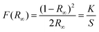
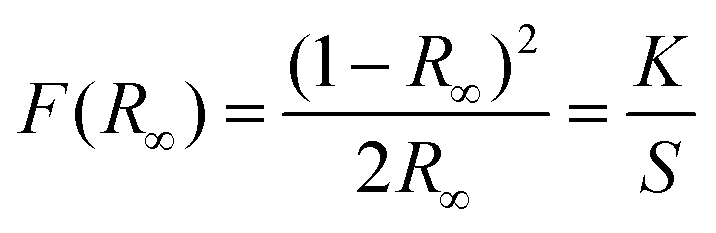
Eqn (2) and (3) refer to the Kubelka–Munk equation and Tauc equation, respectively, which are commonly used in the field to determine the optical band gap of materials using their reflectance spectra:40,41
| |  | (2) |
The comprehensive theory and significance of the employed symbols were addressed in our previous article.39 The Kubelka–Munk plot of the aforementioned phosphors is shown in Fig. S4(b).† The observed optical band gaps of NaLa(MoO4)2, NaLa0.97Pr0.03(MoO4)2 and NaLa0.86Pr0.03Yb0.11(MoO4)2 phosphors are 3.83 eV, 3.63 eV and 3.76 eV, respectively. The observed decrease in the optical band gap of doped and co-doped samples suggests that the formation of new electronic states below the conduction band in the doped and co-doped materials is due to an increase in charge carrier concentration.11
4. Multimodal light emission studies
Multimodal luminescence refers to the emission of light through different processes, including downshift (DS), quantum cutting (QC), and upconversion (UC). This phenomenon has gained considerable interest because of its extensive applications in display technologies, multimodal imaging, and optical thermometry, and for improving the performance of photovoltaic cells, among others. However, complete coverage of all luminescence types from Ln3+ doped single host matrices is still lacking in the existing literature. The emission of light via the aforementioned processes is contingent on certain processes, which will be explained in the following sections that specifically examine luminescence through different modes.
4.1. Downshifting (DS) emission
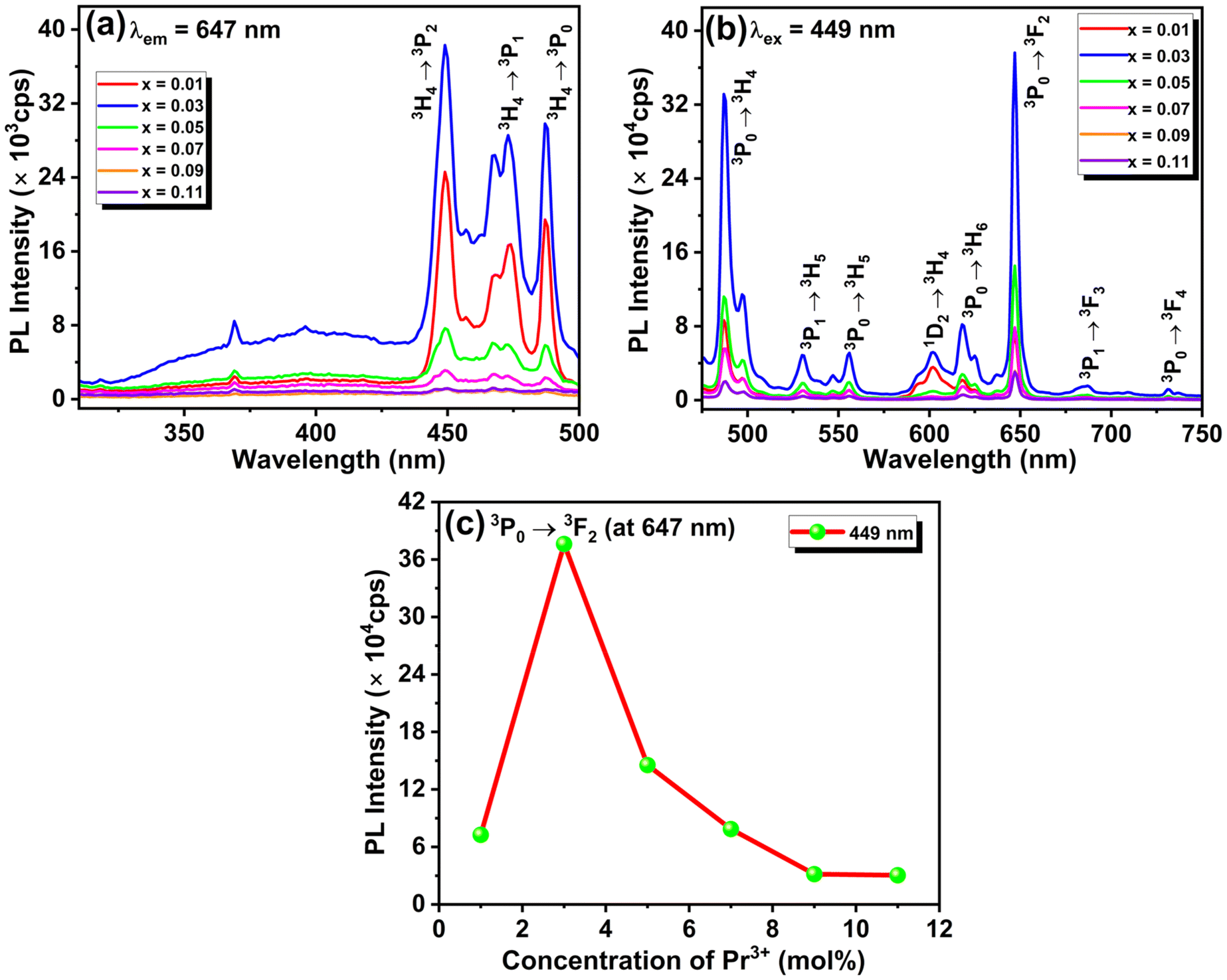
The material's photoluminescence properties can be determined by examining its excitation spectra, emission spectra, and luminescence lifetime. Fig. 2(a) represents the photoluminescence (PL) excitation spectra of NLMO phosphors activated with Pr3+, measured at a 647 nm emission wavelength. The spectra exhibit distinctive absorption peaks of Pr3+ at 449, 468, and 486 nm, caused by 4f–4f electronic transitions from the 3H4 (ground state) to 3P2, 3P1, and 3P0 multiplet states of Pr3+ ions, respectively, which is well aligned with the UV-Vis diffuse reflectance spectra, as shown in Fig. S4(a).† The samples were excited using the most intense characteristic excitation peak at 449 nm of Pr3+ ions. The intense excitation bands in the blue region support the utilization of NMLO:Pr3+ phosphors in developing InGaN (blue) LED-excited pc-LEDs. Additionally, the InGaN chip that emits blue light can serve a dual function, acting as both an excitation source for NMLO:Pr3+ phosphors and a supplementary source of blue light. Fig. 2(b) shows the photoluminescence (PL) emission spectra of NLMO with different concentrations of Pr3+ ions, excited at 449 nm. The emission peaks of Pr3+ ions are observed at specific wavelengths: one cyan emission peak at 486 nm (3P0 → 3H4), two green emission peaks at 530 nm (3P1 → 3H5) and 556 nm (3P0 → 3H5), several low-intensity red emission peaks at 602 nm (1D2 → 3H4), 688 nm (3P1 → 3F3), and 731 nm (3P0 → 3F4) and two strong red emission peaks at 618 nm (3P0 → 3H6) and 647 nm (3P0 → 3F2) of Pr3+ ions.23,42 The emission peaks at 486 and 647 nm exhibit greater intensity than all other peaks under excitation at both wavelengths due to the significant population of the 3P0 excited state. Furthermore, the hypersensitive 3P0 → 3F2 transition of Pr3+ (ΔS = 0, ΔJ = 2; S = spin angular momentum, and J = total angular momentum) is responsible for the emission at 647 nm.43 This transition is a forced electric dipole transition, and it is strongly influenced by the field environment around the Pr3+ ions. The observed emission bands under a suitable excitation wavelength could be understood through the schematic energy level diagram displayed in Fig. 5(d).
 |
| | Fig. 2 (a) Excitation spectra of NaLa0.97Pr0.03(MoO4)2 phosphors monitored at 647 nm emission wavelength, (b) emission spectrum of NaLa0.97Pr0.03(MoO4)2 phosphors monitored at λex = 449 nm, and (c) variation of the emission intensity with the percentage of NaLa0.97Pr0.03(MoO4)2 (0.01 ≤ x ≤ 0.11) phosphors monitored at λex = 449 nm. | |
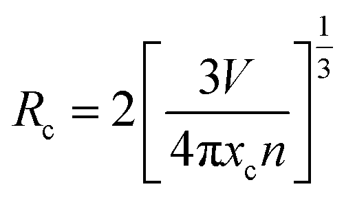
The concentration of activator ions influences the luminescence intensity of the material. To achieve the maximum intensity, it is necessary to incorporate an appropriate quantity of activator ions. Fig. 2(c) shows that the emission intensity initially increases as the concentration of Pr3+ ions increases, reaching its optimum value at 3 mol% and then reducing with a further increase in concentration. The initial rise in intensity as a function of Pr3+ concentration is due to the increased quantity of favourable luminescent sites. Nevertheless, the reduction in intensity beyond the optimal value results from the concentration quenching phenomenon. When the number of activator ions (Pr3+ ions) in the host lattice exceeds a certain threshold, their distance from each other reduces, and some of the Pr3+ ions start to occupy the interstitial sites instead of the lattice sites of La3+. The Pr3+ ions in the interstitial positions serve as luminescence quenchers, absorbing the photons that would otherwise be emitted as light and releasing the energy through non-radiative multiphonon emissions. The energy transfer process involved in concentration quenching can be understood by calculating the critical energy transfer distance (Rc).44
| |  | (4) |
Where V, xc, and n stand for the volume of a unit cell at the optimum concentration, n is the number of possible doping sites in the unit cell, and xc signifies the optimum doping concentration, respectively. V, xc, and n for the material are 335.33 Å3, 0.03, and 2, respectively. Based on eqn (4), if Rc is below 5 Å, luminescence is quenched due to exchange interactions. If Rc is above 5 Å, luminescence is quenched because of electric-multipole interactions. In the present scenario, the Rc value is 22.02 Å, above the threshold of 5 Å, indicating that electric-multipole interaction is the reason behind concentration quenching. But this electric-multipolar interaction consists of several types like dipole–dipole (d–d), dipole–quadrupole (d–q), and quadrupole–quadrupole (q–q) interactions. To know the particular type of multipolar interactions involved in the luminescence quenching, Dexter and Van's theory was used for multipolar interaction, which is represented by the following equation:40
| |  | (5) |
The PL emission intensity and corresponding doping concentration are denoted by I and x, respectively. In contrast, β and k represent the constants for the given host lattices. The interaction type between rare-earth ions is represented by Q, where Q = 6, 8, and 10 correspond to dipole–dipole (d–d), dipole–quadrupole (d–q), and quadrupole–quadrupole (q–q) interactions, respectively. Fig. S5† depicts the logarithmic plot of I/x vs. x for NaLa1−xPrx(MoO4)2 phosphors at an excitation wavelength of 449 nm. The plot of log (I/x) vs. log(x) is found to be relatively linear, with a slope of −3.05 and a value of Q is obtained around 9.15 by using eqn (5), which is approaching the minimal Q value of 10. Therefore, it is confirmed that the interaction involved in concentration quenching is quadrupole–quadrupole (q–q) interaction in NaLa1−xPrx(MoO4)2 phosphors.
4.2. Quantum cutting (QC) emission
In the QC phenomenon, typically, higher energy photons get converted into two or more lower energy photons through an energy transfer pathway. It was first observed in YF3:Pr3+ (ref. 45) in 1974 and has since been extensively studied in several fluoride-based host materials like KY3F10:Pr3+/Yb3+,46 YOF:Pr3+/Yb3+,17 NaYF4:Pr3+/Yb3+,47 Ba4Y3F17:Pr3+/Yb3+,48etc. As fluoride materials have relatively low phonon energy (∼420 cm−1), which helps in reducing the non-radiative transition via multiphonon emission and, therefore, favours efficient energy transfer and high fluorescence quantum yield. However, the high toxicity and low chemical stability of fluoride-based materials hinder their applicability.6 To overcome this problem, oxide-based host materials are used due to their non-toxicity, chemical stability, ease of synthesis, and strong absorption in the n-UV region. Considering this criterion, researchers have recently used oxide-based host phosphors with QC emission as coating materials to improve the photovoltaic performance of c-Si solar cells.19Fig. 3(a and b) show the emission spectra of NaLa0.97−yPr0.03Yby(MoO4)2 samples excited at 325 nm recorded in the visible (400 nm–800 nm) and near-infrared (800–1050 nm) regions, respectively. Fig. 3(a) shows different visible emission bands related to the various f–f transitions of Pr3+ ions, as mentioned in the above section of downshifting emission studies. Fig. 3(b) indicates the NIR emission spectra, which contain emission bands at around 982 nm (3P0 → 1G4), 1016 nm (1D2 → 3F4), and 976 nm (2F5/2 → 2F7/2) related to the electronic transitions of Pr3+ and Yb3+ ions, respectively.49 Specifically, the emission bands of Pr3+ and Yb3+ ions in the NIR region are appealing for solar cell applications because they align with the most efficient region of c-Si solar cells. From Fig. 3(b), it is clear that as the concentration of Yb3+ increases, the emission intensity of the Pr3+ peak at 647 nm (3P0 → 3F2) gradually attenuates in the visible region, while in the NIR region the emission intensity of the band at 976 nm observed due to the 2F5/2 → 2F7/2 transition of Yb3+ increases up to 3 mol% of Yb3+. However, it eventually decreases due to concentration quenching caused by non-radiative energy transfer (ET) between neighbouring Yb3+ ions. The observed NIR emission band of Yb3+ (2F5/2 → 2F7/2) can only be achieved upon 325 nm (22690 cm−1) excitation through energy transfer (ET) from Pr3+, as Yb3+ does not have an electronic state above 10240 cm−1. Energy transfer (ET) from Pr3+ to Yb3+ can occur via two pathways. The energy level diagram could explain the different pathways to achieve NIR emissions and energy transfer from Pr3+ to Yb3+ ions, as shown in Fig. 5(d).
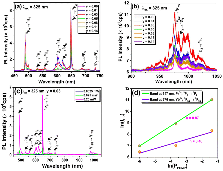 |
| | Fig. 3 (a and b) Concentration-dependent emission spectra of NaLa0.97−yPr0.03Yby(MoO4)2 phosphors (0.00 ≤ y ≤ 0.14) upon 325 nm laser excitation, in the visible and NIR regions, respectively, and (c and d) power-dependent QC emission spectra and the ln–ln plot of intensity vs. the pump plot of NaLa0.94Pr0.03Yb0.03(MoO4)2 samples, respectively. | |
To get a deeper insight into the optical process involved in QC emission, the authors measured the power-dependent emission spectra of the NaLa0.94Pr0.03Yb0.03(MoO4)2 sample in the visible-NIR range using 325 nm laser excitation. Furthermore, this power-dependent emission data were analyzed by monitoring the emission intensities of the 647 nm: 3P0 → 3F2 (Pr3+) and 976 nm: 2F5/2 → 2F7/2 (Yb3+) bands with the applied excitation power, as displayed in Fig. 3(c). The ln(I) vs. ln(P) plots for the emission bands at 647 nm and 976 nm are illustrated in Fig. 3(d). From the plot, it is evident that the emission band related directly to the excited Pr3+ ions shows a higher response with the applied power compared to the emission band associated with the indirectly excited Yb3+ ions. This may be due to the fact that only a few of the excited Pr3+ ions participate in transferring their energy to nearby Yb3+ for the NIR emission. The variations of these emission bands within the low-power region follow the following relationship:6
where
I signifies the emission intensity,
P is the excitation power, and
n refers to the number of photons required for light emission under specific processes. In the present case, the observed value of
n,
i.e., the slope value for the ln(
I)
vs. ln(
P) for the visible emission, is
n = 0.87 ≈ 1.0, and for the NIR emission, it is
n = 0.40 ≈ 0.5. Thus, it is clear that the observed visible emission is through the linear optical process, and the observed NIR emission is through the non-linear optical process. Additionally, it supports the assumption of conversion of one high-energy photon into two low-energy photons for the QC process. Similar types of observations have been reported by other researchers in KYb(WO
4)
2:Tb
3+,
50 Ca
12Al
14O
33:Yb
3+/Eu
3+ oxide
51 based phosphor materials.
4.3. Decay kinetics and quantum cutting efficiency
The decay kinetic studies of the samples were performed to quantitatively estimate the energy transfer and internal quantum cutting efficiency from Pr3+ to Yb3+ ions. The decay times of Pr3+ doped NLMO and Pr3+/Yb3+ co-doped NLMO samples were recorded for the most intense emission band, i.e., for 647 nm of Pr3+ by fixing the excitation wavelength at 447 nm. In both cases, the observed experimental data were fitted with the single exponential function as mentioned below:39| |  | (7) |
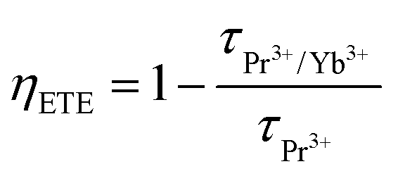
The decay emission intensities at any time t and time 0 are denoted as I and I0, respectively. τ is the decay time, which could be obtained by fitting the data in eqn (7). Fig. 4(a and b) display the decay time profile of Pr3+ and Pr3+/Yb3+ doped NLMO samples, respectively. From the decay time profile, it is clear that the observed maximum decay time in single Pr3+ doped NLMO samples is the maximum in the optimized sample, i.e., for 3 mol% of Pr3+, and it was around 6.52 μs. Whereas the decay time in the case of co-doped samples in which the amount of Pr3+ was fixed at 3 mol% and the amount of Yb3+ was varied from 1 to 14 mol%, decreases continuously with increasing the amount of Yb3+, as mentioned in Table S4.† This decrement in the decay time of Pr3+ may be due to the fact that some of the excited Pr3+ ions transfer their energy to the nearby Yb3+ for QC emission. It is important to mention that the PL emission in the visible region follows a similar trend to that seen in the decay time with the increasing amount of Yb3+. Thus, in this type of system, energy transfer from Pr3+ to Yb3+ ions can be assumed through the cooperative energy transfer (CET) channel and the energy transfer efficiency (ηETE) can be calculated using the following relationship:6
| |  | (8) |
where the decay times of Pr
3+/Yb
3+ and Pr
3+-doped samples are denoted as
τPr3+/Yb3+ and
τPr3+, respectively. The determination of the internal quantum efficiency (
ηQE) for various quantities of Yb
3+ can be achieved by utilizing the provided energy transfer efficiency values and applying the following relationship:
6,19| | | ηQE = ηPr(1 − ηETE) + 2ηETE | (9) |
 |
| | Fig. 4 Decay time profile of (a) NaLa1−xPrx(MoO4)2 (0.01 ≤ x ≤ 0.11) and (b) NaLa0.97−yPr0.03Yby(MoO4)2 (0.01 ≤ y ≤ 0.14) samples, recorded by fixing emission at 647 nm and excitation at 447 nm. | |
In the aforementioned relationship, the initial component represents the visible photons emitted by Pr3+ ions, while the subsequent term refers to the near-infrared (NIR) photons emitted by Yb3+ ions. In this context, ηPr represents the quantum efficiency of Pr3+, and it can be taken as equal to 1 in an ideal case when the probability of non-radiative transition is zero, i.e., for maximum possible efficiency. Table S4† represents the variations in calculated parameters ηETE and ηQE with the amount of Yb3+ ions. In the present case, the maximum possible quantum-cutting efficiency (ηQE) is for the samples having compositions NaLa0.83Pr0.03Yb0.14(MoO4)2 and it was around 109%. This indicates that when 100 photons of 449 nm radiation are absorbed by the sample having compositions NaLa0.83Pr0.03Yb0.14(MoO4)2, then it will generate 18 photons with NIR-region wavelengths (900–1100 nm) and 91 photons with visible-region energy (emission of Pr3+).
4.4. Upconversion (UC) emission
The UC emission studies of Yb3+/Pr3+ co-doped samples were performed using an NIR 980 nm laser excitation source. In UC emission studies, the amount of Pr3+ was fixed at 3 mol% as it was optimized in the DS emission study, and then the amount of Yb3+ was varied from 1 to 14 mol%, as displayed in Fig. 5(a). The presence of Yb3+ in the NaLa0.97Pr0.03(MoO4)2 phosphor is essential to achieve the UC emission, as no energy level in Pr3+ corresponds to the 980 nm excitation wavelength. Under 980 nm laser excitation, Yb3+ ions absorb energy and transfer their energy to nearby Pr3+ ions for visible UC emission. The observed UC emission exhibits similar emission bands as observed in the DS emission study due to various f–f transitions of Pr3+ ions. Initially, the strength of observed UC emission bands increases with the amount of Yb3+, and it reaches a maximum of 11 mol% of Yb3+ and then declines because of concentration quenching.
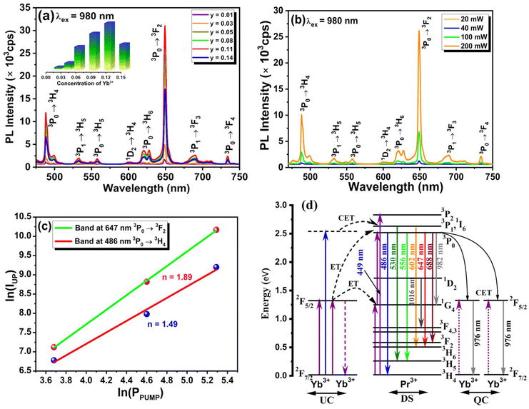 |
| | Fig. 5 (a) Concentration-dependent UC emission spectra of NaLa0.97−yPr0.03Yby(MoO4)2 phosphors (0.01 ≤ y ≤ 0.14) under 980 nm laser excitation, (b) power-dependent UC emission spectra of NaLa0.86Pr0.03Yb0.11(MoO4)2 phosphors, (c) ln–ln plot of intensity vs. pump power for NaLa0.86Pr0.03Yb0.11(MoO4)2 phosphors, and (d) schematic partial energy level diagram of Pr3+/Yb3+ ions to explain the observed emission bands under different excitation wavelengths. | |
Further, the power-dependent UC emission spectra were recorded to know the number of photons involved in the observed UC emission band, as shown in Fig. 5(b). On analyzing the power-dependent UC emission spectra using eqn (6), it was found that two NIR photons are required to get the most prominent 647 and 486 nm visible UC emission bands from Pr3+ ions shown in Fig. 5(c). A schematic energy level diagram was drawn, as illustrated in Fig. 5(d), to explain the observed UC emission in the present system. For details, one may refer to the work of Balaji S. et al.52
5. Thermal stability
The phosphor's thermal stability is significant for its use in lighting and display device applications. Fig. 6(a) shows the temperature-dependent emission spectra of NaLa0.97Pr0.03(MoO4)2 phosphors monitored at a 449 nm excitation wavelength with temperatures ranging from 298 K to 448 K. From Fig. 6(a), it is clear that upon increasing the temperature, the emission intensity of each peak decreases with a different rate without losing its spectrum pattern, owing to the thermal quenching phenomenon. Fig. 6(b) illustrates the relationship between normalized intensity variations with rising temperature for four major peaks of the Pr3+ ion. The temperature-dependent change in the relative integrated intensity of the 647 nm emission band maintained approximately 41% of its maximum value at 423 K, as shown in Fig. 6(c).
 |
| | Fig. 6 (a) Temperature-dependent emission spectra of NaLa0.97Pr0.03(MoO4)2 phosphors excited at 449 nm. (b) Bar diagram representing the normalized intensity variation as a function of temperature for four major peaks of Pr3+, (c) normalized integral intensity variation as a function of temperature, and (d) the  vs. 1/kT plot for the determination of activation energy. vs. 1/kT plot for the determination of activation energy. | |
Furthermore, the activation energy (ΔEa) obtained from the analysis of temperature-dependent emission spectra is an important thermal quenching parameter and was calculated by the Arrhenius equation given below:11
| | 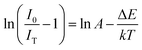 | (10) |
where
I0 and
IT signify the emission intensity at 0 K temperature and at any temperature
T, respectively. ln
A is the constant frequency factor,
k denotes the Boltzmann constant (8.629 × 10
−5 eV K
−1),
T is the temperature and activation energy is defined by Δ
Ea. In this case, the value of activation energy for the 647 nm band was obtained by linearly fitting
 vs.
vs. 1/
kT, and it is found to be 0.44 eV and is represented by the slope of the fitted line, as shown in
Fig. 6(d). The obtained high value of Δ
Ea indicates that the phosphor has good thermal stability. The obtained value of Δ
Ea was around 0.44 eV, which is relatively higher than that of the others previously reported for Pr
3+ doped phosphors.
43,53–56
6. Applications
6.1. Optical thermometry
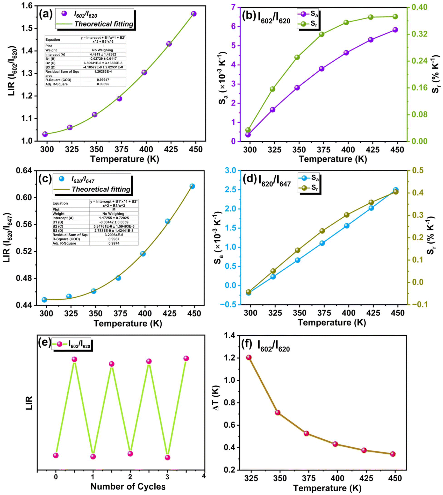
To shed some light on optical thermometry properties, the fluorescence-based temperature sensing technique utilizes the temperature-sensitive fluorescence characteristics of luminescent materials, presenting various advantages over conventional methods such as thermocouple detectors. This method demonstrates robust functionality even in environments characterized by intense electromagnetic interference, electrical sparks, and corrosive conditions. This technique has two primary modalities: one that relies on the measurement of fluorescence lifetime and the other that depends on the measurement of luminescence intensity ratio (LIR). Fluorescence lifetime-based temperature evaluation faces limitations, particularly with the thermalized energy levels that are usually used. However, the FIR technique provides an alternate solution. The majority of energy level pairs associated with rare earth ions remain non-thermalized, and the FIR ratio of these pairs exhibits temperature-dependent behaviour. However, it is difficult to populate these non-thermalized energy levels via thermal excitation because of significant differences in energy levels. While FIR technology traditionally depends on transitions between thermally coupled levels (TCLs), its effectiveness in temperature measurement is constrained by notable restrictions.57 Therefore, a polynomial function can accurately represent the temperature-dependent FIR emissions of non-thermally connected levels (NTCLs).
The following equation can be utilized to determine their LIR relationship:58
| | | LIR = A + BT + CT2 + DT3 | (11) |
here,
A,
B,
C and
D are constants that can be determined by fitting the LIR to the temperature data. The luminescence ratios were derived from the integrated values of the luminescence peaks.
Additionally, the absolute Sa and relative Sr temperature sensitivities, which are crucial parameters for temperature measurement, can be calculated using the following equations:59
| | 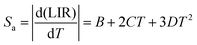 | (12) |
and
| | 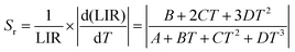 | (13) |
The values of Sa and Sr can be evaluated by using eqn (12) and (13), respectively, based on the various non-thermally coupled (NTCL) energy levels. Fig. 7(a–d) illustrate the changes in LIR and sensitivity parameters Sa and Sr as the temperature varies from 298 to 448 K in the Pr3+ doped samples. Table 1 provides an overview of the estimated maximum sensitivity parameters for both cases. It is evident from the table that the Pr3+ doped NLMO sample exhibits the highest relative sensitivity for the chosen pair of NTCLs I620/I647. The obtained sensitivity parameters were also compared with the sensing parameters observed in other Pr3+ doped phosphor samples, as presented in Table 1. Based on the analysis, it can be concluded that the prepared sample holds promise for use in contactless optical temperature sensing applications.
 |
| | Fig. 7 LIR variation with T for NaLa0.97Pr0.03(MoO4)2 phosphors in the temperature range of 298 to 448 K under a 449 nm excitation wavelength for (a) I602/I620 and (c) I620/I647. The dependence of absolute sensitivity (Sa) and relative sensitivity (Sr) on temperature for (b) I602/I620 and (d) I620/I647 for NTCL, (e) repeatability measurement, and (f) uncertainty measurement at variable temperatures. | |
Table 1 The maximal values of sensitivity parameters (Sa and Sr) in different types of Pr3+ doped samples
| Sample |
LIR (NTCLs) |
S
a-Maximum (×10−3 K−1) (at temperature) |
S
r-Maximum (% K−1) (at temperature) |
Ref. |
| NLMO:Pr3+ |
I
602/I620 |
5.8 (448 K) |
0.37 (448 K) |
This work |
| NLMO:Pr3+ |
I
620/I647 |
2.5 (448 K) |
0.41 (448 K) |
This work |
| Sr3Sc2Ge3O12:Pr3+ |
— |
— |
0.32 (650 K) |
60
|
| NaSrGd(MoO4)3:Pr3+ |
I
530/I619 |
1.5 (290 K) |
0.52 (290 K) |
61
|
| LaMgNbO3:Pr3+ |
I
492/I619 |
32.1 (523 K) |
0.71 (473 K) |
62
|
| YF3:Pr3+ |
I
700/I723 |
— |
0.57 (293 K) |
63
|
To ascertain the commercial viability of the prepared samples as temperature-sensitive probe materials, it is imperative to assess not only the relative and absolute sensitivity parameters but also repeatability and uncertainty (ΔT). In this work, the I602/I620 sample showed the highest absolute sensitivity values and was then examined for repeatability and uncertainty measurements. Fig. 7(e) depicts the cyclic repeatability of LIR (I602/I620) during several measurement cycles and temperature fluctuations.
The temperature uncertainty (ΔT) can be calculated using the following equation:64,65
| |  | (14) |
The standard deviation in the LIR value is denoted as ΔLIR. Fig. 7(f) illustrates the uncertainty in the temperature measurement of the NaLa0.97Pr0.03(MoO4)2 phosphor for I602/I620. The temperature uncertainty falls within a range of 0.3–1.3 K. The low uncertainty value validates the appropriateness of the produced phosphor for temperature-sensing applications. Another essential parameter on which the above parameters can rely is percentage repeatability (R), and it can be expressed as66
| |  | (15) |
where
Δm indicates the mean LIR values for four cycles and
Δi is the LIR value in four repeated radiation cycles. The variation of LIR values in four consecutive cycles is shown in
Fig. 7(e). In the present case, estimated values of
R within the temperature range of 298 to 448 K are more than 98, so it can be said that the sample exhibits good thermal repeatability.
6.2. Fabrication of pc-LED and plant growth
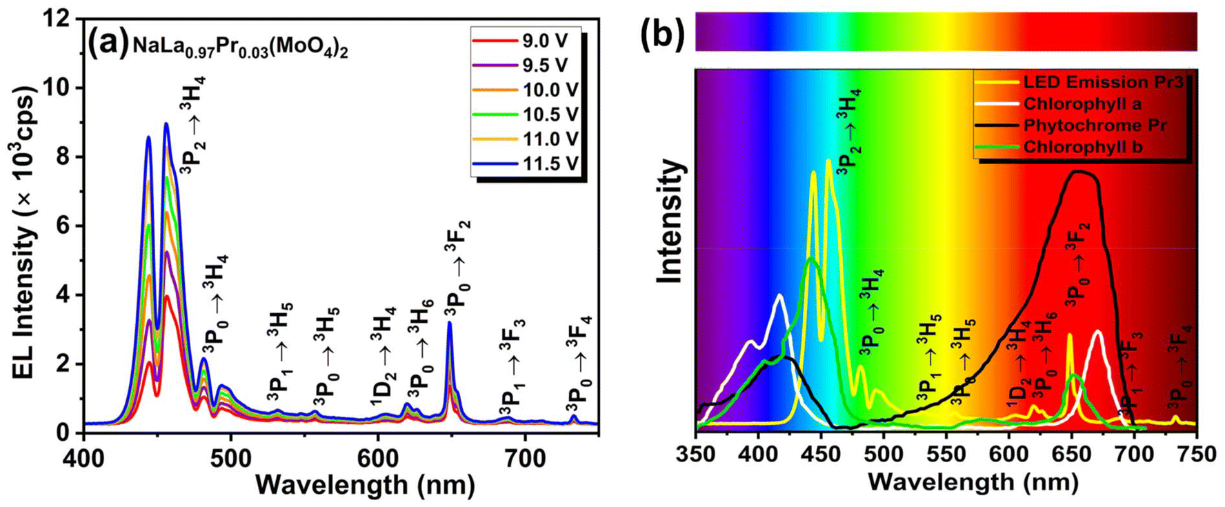
To test the practical use of the prepared phosphor in a phosphor-coated LED (pc-LED) device, the pc-LED device was developed by combining a commercially available blue LED (InGaN) chip with the chosen NaLa0.97Pr0.03(MoO4)2 phosphor. The selected phosphor and epoxy resin (product name: CLEARRESIN) were mixed in a 1:10 wt% ratio and blended thoroughly using ultrasonication. Once the mixing was complete, a smooth layer of paste was carefully applied to the blue LED chip using the doctor blade technique. The developed pc-LED was then placed in an oven at 60 °C for 3 h to allow the paste to dry.59 In this case, a blue LED was selected because its emission was approximately in the 430–440 nm range and aligned with one of the prominent excitation bands observed through the 3H4 → 3P2 transition of Pr3+ ions. The emission spectra of the developed pc-LED device as a function of applied voltage are recorded and displayed in Fig. 8(a). The observed emission spectra of pc-LED include an emission band at around 440 nm attributed to the leakage of the used LED chip and emission bands resulting from various f–f transitions of Pr3+ in the visible region. The strength of the emission bands increases with the increase in the applied voltage, which indicates the voltage stability of the developed pc-LED. This increase in intensity does not disrupt the band pattern, indicating the stability of the developed pc-LED under varying voltage conditions. Furthermore, to demonstrate the applicability of the developed pc-LED in plant growth, the observed emission spectrum of the developed pc-LED was compared with the absorption spectra of chlorophylls (a,b) and phytochrome, as shown in Fig. 8(b). Here, it is to be noted that chlorophylls (a,b) and phytochrome are the compounds found in plants that are responsible for plant growth. From the comparison, it is clear that the observed emissions in the blue region and red regions of the developed pc-LED fall in the prominent absorption regions of chlorophyll and phytochrome, respectively. Thus, such a pc-LED could be used as a light source for indoor plant applications. Similarly, other researchers have also suggested the use of Eu3+, Sm3+, and Mn4+ doped red colour-emitting phosphor-based pc-LEDs for indoor plant applications.67–69 But the advantage of the presented pc-LED is that it utilizes blue and red emission to cover the absorption of chlorophyll as well as phytochrome.
 |
| | Fig. 8 (a) Emission spectra of the developed pc-LED at various applied voltages, and (b) comparison of the emission spectrum of the developed pc-LED at a fixed applied voltage with the absorption spectra of chlorophylls a and b and phytochrome of the plant. | |
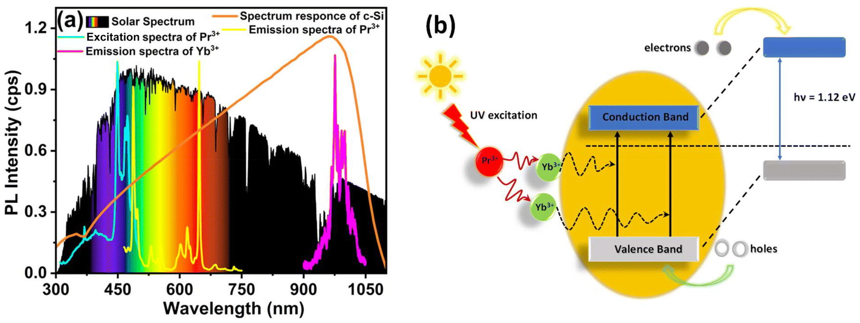
6.3. c-Si solar cells
The spectral range of 900–1100 nm is found to be the most effective for the operation of c-Si solar cells. However, these cells have limited responsiveness towards shorter wavelengths (300–500 nm) due to thermal losses. It is worth noting that solar irradiation is abundant in this range. Therefore, materials that can capture solar energy in the 300–500 nm range and convert it into near-infrared (NIR) emissions falling within the 900–1100 nm range are ideal for use as coatings on c-Si solar cells to enhance the photovoltaic performances.59Fig. 9(a) shows a comparison of the normalized spectral irradiance of solar radiation (derived from ASTM G-173-03), the spectral response curve of c-Si solar cells, and the excitation/emission spectrum of a NaLa0.94Pr0.03Yb0.03(MoO4)2 sample. This comparison highlights the ability of the prepared Yb3+/Pr3+ co-doped NLMO sample to harness solar energy in the 300–450 nm range and convert it into NIR emissions within the 900–1100 nm band. The emission spectrum of the prepared sample aligns with the most efficient region of c-Si solar cells, indicating its potential to enhance photovoltaic performance. Fig. 9(b) presents a schematic model that demonstrates how the prepared co-doped sample could improve the efficiency of solar cells using the quantum cutting (QC) process. When the sample is stimulated by UV light (240–393 nm), the Pr3+ ions are excited to move to the higher energy level 3P2, from which they undergo radiative transitions. Among the excited Pr3+ ions, a few of the Pr3+ ions participate in transferring their energy to nearby Yb3+ ions through a cooperative energy transfer process, in which a single Pr3+ ion excites two Yb3+ ions to emit near-infrared light at a wavelength of 980 nm, with an energy of 1.26 eV. This process generates two electrons that can surpass the band gap (Eg = 1.12 eV) of single-crystalline Si, potentially doubling the electric current. Thus, the prepared co-doped phosphors can potentially improve c-Si solar cell efficiency.
 |
| | Fig. 9 (a) Comparison among the solar spectrum, the spectral response curve of c-Si solar cells, and the observed emission/spectrum of the NaLa0.86Pr0.03Yb0.11(MoO4)2 sample, and (b) representation of the model of how the prepared co-doped sample can improve the photovoltaic performance of the c-Si solar cells. | |
7. Conclusion
In summary, a series of Pr3+ doped and Pr3+/Yb3+ co-doped NaLa(MoO4)2 phosphor samples were synthesized using the facile solid-state reaction method. The multimodal light emission characteristics of the samples were inspected systematically. In the visible region of the emission spectra recorded under 449 and 980 nm excitation, the emission band lies in the red region and arises from the dominant 3P0 → 3F2 transition of Pr3+. The investigation of optical concentration quenching indicates that the quadrupole–quadrupole (q–q) interaction in NaLa1−xPrx(MoO4)2 phosphors is responsible for the concentration quenching. Additionally, the emission in the visible region is decreased in Pr3+/Yb3+ co-doped samples, which may be due to energy transfer from Pr3+ ions to Yb3+ ions, which results in the appearance of the NIR emission band. This energy transfer increases with the amount of Yb3+, which is further supported by the decay kinetics measurements. In this case, the NaLa0.83Pr0.03Yb0.14(MoO4)2 composition exhibits a maximum energy transfer and an internal quantum cutting efficiency of approximately 8.58 and 109%, respectively. For the practical applicability of the prepared sample, it was first tested for optical thermometry using the LIR technique. The observed maximum absolute and relative sensitivities are 2.5 × 10⁻³ K−1 (at 448 K) and 0.41% K−1 (at 448 K), respectively.
Furthermore, the optimized sample was used to develop a pc-LED by coupling it with a blue LED chip, and the developed pc-LED exhibited voltage stability. The comparison of the observed emission/excitation spectrum, the absorption spectrum of chlorophyll/phytochrome, and the spectral response curve of the solar cells suggests that the prepared samples have potential for use in solar cells and plant growth applications. Thus, the prepared phosphor materials with multimodal light-emitting capabilities can be used for multifunctional applications.
Data availability
The datasets generated and analysed during the current study are not publicly available but are available from the corresponding author upon reasonable request.
Conflicts of interest
The authors declare no financial competing interest.
Acknowledgements
The authors, C. Shivakumara and Sonali Tomar, acknowledge the Chemical Science Division, Indian Institute of Science, Bangalore, for extending the instrumental facility. The authors are greatly acknowledged. Dr Kaushal Kumar is grateful to the Department of Science and Technology (DST-SERB) in New Delhi, India, for the instrumental facility at Physics Dept., IIT(ISM), Dhanbad.
References
- X. Shang, I. Song, G. Y. Jung, W. Choi, H. Ohtsu, J. H. Lee, J. Y. Koo, B. Liu, J. Ahn, M. Kawano, S. K. Kwak and J. H. Oh, Nat. Commun., 2018, 9, 3933 CrossRef PubMed.
- C. Meng, N. Muralidharan, E. Teblum, K. E. Moyer, G. D. Nessim and C. L. Pint, Nano Lett., 2018, 18, 7761–7768 CrossRef CAS PubMed.
- C. Zhang, W. Wu, R. Q. Li, W. X. Qiu, Z. N. Zhuang, S. X. Cheng and X. Z. Zhang, Adv. Funct. Mater., 2018, 28, 1804492 CrossRef.
- S. Chen, N. Zhang, B. Zheng, B. Zhang and J. Song, ACS Appl. Mater. Interfaces, 2018, 10, 44706–44715 CrossRef CAS PubMed.
- A. Du, H. Wang, B. Zhou, C. Zhang, X. Wu, Y. Ge, T. Niu, X. Ji, T. Zhang, Z. Zhang, G. Wu and J. Shen, Chem. Mater., 2018, 30, 6849–6857 CrossRef CAS.
- N. K. Mishra, K. Shwetabh, U. K. Gautam and K. Kumar, Phys. Chem. Chem. Phys., 2023, 25, 11756–11770 RSC.
- S. K. Karunakaran, G. M. Arumugam, W. Yang, S. Ge, S. N. Khan, X. Lin and G. Yang, ACS Sustainable Chem. Eng., 2021, 9, 1035–1060 CrossRef CAS.
- G. Chen, T. Y. Ohulchanskyy, S. Liu, W. C. Law, F. Wu, M. T. Swihart, H. Ågren and P. N. Prasad, ACS Nano, 2012, 6, 2969–2977 CrossRef CAS PubMed.
- M. R. M. de Sousa, T. O. Sales, W. Q. Santos, W. F. Silva and C. Jacinto, J. Lumin., 2021, 233, 117919 CrossRef CAS.
- A. K. Singh, S. K. Singh, B. K. Gupta, R. Prakash and S. B. Rai, Dalton Trans., 2013, 42, 1065–1072 RSC.
- Sonali, V. Chauhan, P. C. Pandey and C. Shivakumara, ACS Appl. Opt. Mater., 2024, 2, 41–56 CrossRef CAS.
- N. Niu, P. Yang, W. Wang, F. He, S. Gai, D. Wang and J. Lin, Mater. Res. Bull., 2011, 46, 333–339 CrossRef CAS.
- A. Zhang, Z. Sun, G. Liu, Z. Fu, Z. Hao, J. Zhang and Y. Wei, J. Alloys Compd., 2017, 728, 476–483 CrossRef CAS.
- K. Li and R. Van Deun, Dalton Trans., 2018, 47, 6995–7004 RSC.
- Y. Tai, H. Wang, H. Wang and J. Bai, RSC Adv., 2016, 6, 4085–4089 RSC.
- W. Shockley and H. J. Queisser, J. Appl. Phys., 1961, 32, 510–519 CrossRef CAS.
- N. A. M. Saeed, E. Coetsee and H. C. Swart, Opt. Mater., 2020, 110, 110516 CrossRef CAS.
- S. Ye, B. Zhu, J. Chen, J. Luo and J. R. Qiu, Appl. Phys. Lett., 2008, 92, 141112 CrossRef.
- N. K. Mishra, M. I. Sarkar and K. Kumar, Dalton Trans., 2023, 52, 11658–11670 RSC.
- L. Xie, Y. Wang and H. Zhang, Appl. Phys. Lett., 2009, 94, 061905 CrossRef.
- K. Deng, X. Wei, X. Wang, Y. Chen and M. Yin, Appl. Phys. B, 2011, 102, 555–558 CrossRef CAS.
- L. J. Borrero-González, L. A. O. Nunes, G. S. Bianchi, F. B. G. Astrath and M. L. Baesso, J. Appl. Phys., 2013, 114, 013103 CrossRef.
- W. Romero-Romo, S. Carmona-Téllez, R. Lozada-Morales, O. Soriano-Romero, U. Caldiño, M. E. Álvarez-Ramos, M. E. Zayas and A. N. Meza-Rocha, Opt. Mater., 2021, 116, 111009 CrossRef CAS.
- S. Sinha, M. K. Mahata and K. Kumar, New J. Chem., 2019, 43, 5960–5971 RSC.
- M. K. Mahata, T. Koppe, T. Mondal, C. Brüsewitz, K. Kumar, V. Kumar Rai, H. Hofsäss and U. Vetter, Phys. Chem. Chem. Phys., 2015, 17, 20741–20753 RSC.
- G. Tamulaitis, P. Duchovskis, Z. Bliznikas, K. Breive, R. Ulinskaite, A. Brazaityte, A. Novičkovas and A. Žukauskas, J. Phys. D: Appl. Phys., 2005, 38, 3182–3187 CrossRef CAS.
- L. Ma, D. J. Wang, Z. Y. Mao, Q. F. Lu and Z. H. Yuan, Appl. Phys. Lett., 2008, 93, 144101 CrossRef.
- M. Olle, A. Viršilė, M. Olle and A. Viršilė, Agric. Food Sci., 2013, 22, 223–234 CrossRef.
- Z. Mao, J. Chen, J. Li and D. Wang, Chem. Eng. J., 2016, 284, 1003–1007 CrossRef CAS.
- G. D. Massa, H.-H. Kim, R. M. Wheeler and C. A. Mitchell, Hortic. Sci., 2008, 43, 1951–1956 Search PubMed.
- S. B. Stevens and C. A. Morrison, Phys. Rev. B:Condens. Matter Mater. Phys., 1991, 43, 7386 CrossRef CAS PubMed.
- X. Wu, X. Zhao, Q. Ren, L. Du, M. Pei and O. Hai, Ceram. Int., 2022, 48, 18793–18802 CrossRef CAS.
-
C. D. Wagner
, NIST X-ray photoelectron spectroscopy (XPS) database, National Bureau of Standards, Gaithersburg, MD, 1990.
- V. V. Atuchin, J. C. Grivel, A. S. Korotkov and Z. Zhang, J. Solid State Chem., 2008, 181, 1285–1291 CrossRef CAS.
- O. Y. Khyzhun, V. L. Bekenev, V. V. Atuchin, E. N. Galashov and V. N. Shlegel, Mater. Chem. Phys., 2013, 140, 588–595 CrossRef CAS.
- R. Krishnan, J. Thirumalai, I. B. Shameem Banu and R. Chandramohan, J. Mater. Sci.: Mater. Electron., 2013, 24, 4774–4781 CrossRef CAS.
- S. K. Ray, B. Joshi and J. Hur, Nanotechnology, 2022, 33, 395705 CrossRef CAS PubMed.
- Z. Wu, X. Yuan, G. Zeng, L. Jiang, H. Zhong, Y. Xie, H. Wang, X. Chen and H. Wang, Appl. Catal., B, 2018, 225, 8–21 CrossRef CAS.
- S. Tomar, N. K. Mishra, V. Chauhan, K. Kumar and C. Shivakumara, J. Phys. Chem. C, 2024, 128, 10159–10174 CrossRef CAS.
- Sonali and C. Shivakumara, Methods Appl. Fluoresc., 2023, 11, 024001 CrossRef PubMed.
- D. L. Wood, B. L. Aboxatoxies, M. Hill, T. Jersey and J. Tauc, Phys. Rev. B, 1972, 5, 3144 CrossRef.
- Z. E. A. A. Taleb, K. Saidi and M. Dammak, Dalton Trans., 2023, 52, 18069–18081 RSC.
- H. Kaur and M. Jayasimhadri, J. Am. Ceram. Soc, 2021, 104, 5764–5775 CrossRef CAS.
- G. Blasse, Phys. Lett., 1968, 28, 444–445 CrossRef CAS.
- W. W. Piper and J. A. Deluca, J. Lumin., 1974, 8, 344–348 CrossRef CAS.
- D. Serrano, A. Braud, J. L. Doualan, P. Camy, A. Benayad, V. Ménard and R. Moncorgé, Opt. Mater., 2011, 33, 1028–1031 CrossRef CAS.
- M. S. Pudovkin, S. V. Kuznetsov, V. A. Konuyshkin, A. N. Nakladov and V. V. Voronov, Solid State Commun., 2023, 370, 115235 CrossRef CAS.
- M. S. Pudovkin, S. V. Kuznetsov, V. Y. Proydakova, V. V. Voronov and V. V. Semashko, Ceram. Int., 2020, 46, 11658–11666 CrossRef CAS.
- J. Zhao, X. Zhao, Z. Leng and M. Han, Opt. Mater., 2020, 108, 110232 CrossRef CAS.
- W. Stręk, A. Bednarkiewicz and P. J. Dereń, J. Lumin., 2001, 92, 229–235 CrossRef.
- R. V. Yadav, R. S. Yadav, A. Bahadur and S. B. Rai, RSC Adv., 2016, 6, 9049–9056 RSC.
- S. Balaji, D. Ghosh, K. Biswas, G. Gupta and K. Annapurna, Phys. Chem. Chem. Phys., 2016, 18, 33115–33125 RSC.
- J. Grigorjevaite and A. Katelnikovas, J. Mater. Res. Technol., 2020, 9, 15779–15787 CrossRef CAS.
- X. Tian, S. Xu, J. Wen, L. Zhu, C. Ji, Z. Huang, X. Wang, F. Luo, X. Liu, Y. Lu, J. Li, C. Li, Y. Peng, J. Cao and Z. He, Ceram. Int., 2023, 49, 27126–27137 CrossRef CAS.
- X. Kang, W. Lü, Z. Zhu and C. Jia, J. Rare Earths, 2023, 41, 666–672 CrossRef CAS.
- C. Yao and C. Zhang, Spectrochim. Acta, Part A, 2023, 303, 123177 CrossRef CAS PubMed.
- A. Bindhu, J. I. Naseemabeevi and S. Ganesanpotti, Adv. Photonics Res., 2022, 3, 2100159 CrossRef CAS.
- N. Kumar Mishra, M. M. Upadhyay, S. Kumar and K. Kumar, Spectrochim. Acta, Part A, 2022, 282, 121664 CrossRef CAS PubMed.
- N. K. Mishra, A. Kumar and K. Kumar, J. Alloys Compd., 2023, 947, 169440 CrossRef CAS.
- P. Bolek, T. van Swieten, J. Zeler, A. Meijerink and E. Zych, Chem. Mater., 2024, 36, 8894–8909 CAS.
- Z. E. A. Aly Taleb, K. Saidi and M. Dammak, Dalton Trans., 2023, 52, 18069–18081 RSC.
- H. Zhang, Z. Gao, G. Li, Y. Zhu, S. Liu, K. Li and Y. Liang, Chem. Eng. J., 2020, 380, 122491 CrossRef CAS.
- M. Runowski, P. Woźny, I. R. Martín, V. Lavín and S. Lis, J. Lumin., 2019, 214, 116571 CrossRef CAS.
- H. Xu, M. Jia, Z. Wang, Y. Wei and Z. Fu, ACS Appl. Mater. Interfaces, 2021, 13, 61506–61517 CrossRef CAS PubMed.
- V. Chauhan, P. Dixit, P. K. Pandey, S. Chaturvedi and P. C. Pandey, J. Phys. Chem. C, 2023, 127, 19159–19171 CrossRef CAS.
- M. Prasad and V. K. Rai, New J. Chem., 2023, 47, 7381–7390 RSC.
- K. Singh, M. Rajendran, R. Devi and S. Vaidyanathan, Inorg. Chem., 2022, 61, 2768–2782 CrossRef CAS PubMed.
- N. T. Huyen, N. Tu, N. Van Quang, D. Quang Trung, M. T. Tran, N. Van Du, N. D. Hung, D. X. Viet, N. D. Trung Kien and P. T. Huy, ACS Appl. Electron. Mater., 2022, 4, 4322–4331 CrossRef CAS.
- P. Kaithrikkovil Varriam and S. Ganesanpotti, Laser Photonics Rev., 2024, 18, 2400245 CrossRef CAS.
Footnote |
| † Electronic supplementary information (ESI) available: Experimental procedure; Rietveld plot of (a) NaLa(MoO4)2, (b) NaLa0.97Pr0.03(MoO4)2 and (c) NaLa0.94Pr0.03Yb0.03(MoO4)2, (d) crystal structure of NaLa0.97Pr0.03(MoO4)2 and (e) XRD patterns of NaLa0.97−yPr0.03Yby(MoO4)2 (0.00 ≤ x ≤ 0.14) phosphors; high-resolution XPS spectra of NaLa0.92Pr0.03Yb0.05(MoO4)2, XPS survey scan of Na 1s spectra, La 3d spectra, Pr 3d, Yb 4d, Mo 3d spectra and O 1s spectra; FTIR spectra of Pr3+ doped NLMO (0.00 ≤ x ≤ 0.11); diffusion reflectance spectra of pure, Pr3+ doped and Pr3+/Yb3+ doped NLMO and Kubelka–Munk plots of Pr3+ doped and Pr3+/Yb3+ doped NLMO; log(I/x) vs. log(x) plot of NaLa0.97Pr0.03(MoO4)2 (0.01 ≤ x ≤ 0.11); Rietveld refined lattice parameters and unit cell volumes for NaLa1−xPrx(MoO4)2 (0.00 ≤ x ≤ 0.11) compounds; Rietveld refined structural parameters for NaLa0.94Pr0.03Yb0.03(MoO4)2 compounds. Rietveld refined structural parameters for NaLa0.97Pr0.03(MoO4)2 compounds; variations of decay time (τ), energy transfer efficiency (ηETE), and quantum cutting efficiency (ηQE) in Pr3+/Yb3+ co-doped NLMO samples by fixing the amount of Pr3+ and varying the amount of Yb3+ for the emission band at 647 nm under 449 nm excitation. See DOI: https://doi.org/10.1039/d4dt02532f |
|
| This journal is © The Royal Society of Chemistry 2025 |
Click here to see how this site uses Cookies. View our privacy policy here. 
 a,
Neeraj Kumar
Mishra
bc,
Vaibhav
Chauhan
a,
Neeraj Kumar
Mishra
bc,
Vaibhav
Chauhan


 vs. 1/kT plot for the determination of activation energy.
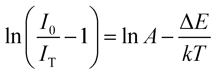
 vs. 1/kT, and it is found to be 0.44 eV and is represented by the slope of the fitted line, as shown in Fig. 6(d). The obtained high value of ΔEa indicates that the phosphor has good thermal stability. The obtained value of ΔEa was around 0.44 eV, which is relatively higher than that of the others previously reported for Pr3+ doped phosphors.43,53–56