Deep reconstruction of crystalline–amorphous heterojunction electrocatalysts for efficient and stable water and methanol electrolysis†
Fang
Zheng
,
Mayur A.
Gaikwad
,
Zhenhua
Fang
,
Suyoung
Jang
and
Jin Hyeok
Kim
 *
*
Optoelectronics Convergence Research Center and Department of Materials Science and Engineering, Chonnam National University, Yongbong-Dong, Buk-Gu, Gwangju 61186, South Korea. E-mail: jinhyeok@chonnam.ac.kr
First published on 20th November 2024
Abstract
During electrocatalytic water splitting, surface reconstruction often occurs to generate truly active species for catalytic reactions, but the stability and mass activity of the catalysts is a huge challenge. A method that combines cation doping with morphology control strategies and constructs an amorphous–crystalline heterostructure is proposed to achieve deep reconstruction of the catalyst during the electrochemical activation process, thereby significantly improving catalytic activity and stability. Amorphous iron borate (FeBO) is deposited on cobalt-doped nickel sulfide (Co-Ni3S2) crystals to form ultrathin nanosheet heterostructures (FeBO/Co-Ni3S2) as bifunctional electrocatalysts for the OER and methanol oxidation reaction (MOR). During the OER process, FeBO/Co-Ni3S2 is deeply reconstructed to form a NiFeOOH/Co-Ni3S2 composite structure with ultrathin nanosheets with abundant amorphous–crystalline interfaces to ensure structural stability. Furthermore, Co-Ni3S2 electrocatalysts were synthesized via nickel foam (NF) self-derivation, which resulted in strong adhesion between the catalyst and substrate and formed a hierarchical structure consisting of interconnected nanosheets with excellent mass transfer and abundant active sites to increase the activity and stability of the electrocatalyst. The dual-electrode electrolyzer requires cell voltages of 1.58 and 1.44 V to achieve water and methanol overall electrolysis at a current density of 10 mA cm−2 and keep working over 100 and 25 h, respectively. This strategy provides a new way to promote reconstruction to construct excellent bifunctional electrocatalysts.
1. Introduction
Electrocatalytic water splitting, which includes oxygen evolution reaction (OER) and hydrogen evolution reaction (HER), is considered a promising method for producing hydrogen (H2) and addressing environmental concerns and energy scarcity.1–3 However, the high energy consumption caused by the high OER overpotential has seriously hindered the large-scale production of H2via the overall water splitting (OWS) technology.4 One strategy to overcome the above-mentioned barriers to the electrolytic production of H2 is to replace the OER with small-molecule oxidation reactions that are thermodynamically more favourable.5,6 The methanol oxidation reaction (MOR) has been extensively attempted due to the following advantages: first, MOR has a lower theoretical thermodynamic potential of 0.58 V and can replace OER as an anode reaction while achieving energy-saving H2 production and the generation of formate as value-added byproducts.7,8 Secondly, formate is an indispensable chemical intermediate in the chemical industry, and its industrial value is higher than methanol.9 Thus, there is tremendous potential to create a versatile hybrid water electrolysis system that combines H2 evolution reaction (HER) and MOR. This system can produce formate and significantly reduce the energy input required to produce H2. Therefore, it is also crucial to carefully design efficient small molecule oxidation reaction electrocatalysts to reduce the overpotential and accelerate the reaction rate.Currently, transition metal-based oxides, nitrides, sulfides, and phosphides have been the main materials studied for electrocatalytic water splitting.10–13 Among them, transition metal sulfides have shown potential as non-noble metal electrocatalysts due to their high catalytic activity, cheap cost, and plentiful reserves.14 In particular, Ni3S2 has a unique electronic structure and excellent electrical conductivity due to Ni–Ni bonds throughout the entire structure.15 However, in most related studies, electrocatalysts are only active toward a single HER, OER, or MOR.16–18 Developing efficient and affordable multifunctional electrocatalysts synthesized from non-noble metals remains difficult. Recent studies have shown that incorporating heteroatoms into Ni3S2 can promote the formation of high-valent Ni (NiOOH),19 which not only increases the electron transfer rate but also improves its intrinsic catalytic activity, thereby showing multifunctional characteristics.15 For instance, by tuning the local electronic structure and coordination environment of Ni3S2 through Fe doping and replacing OER with primary amine oxidation, nitrile compounds and H2 can be efficiently produced.20 Similarly, Co-doping enhances the intrinsic activity of the electrode through the synergistic effect of surface Co and Ni active sites, allowing Co-doped Ni3S2 porous nanocones to demonstrate excellent bifunctional performance.21 In addition to the intrinsic catalytic property of the electrocatalyst, catalytic performance is also influenced by the geometry and configuration of the material.22 Two-dimensional (2D) nanosheet materials can offer large specific surface areas to increase the number of catalytically active sites that are available, thereby significantly improving mass transport and charge diffusion.23,24 In particular, heteroatom-doped electrocatalyst nanosheet structures synthesized using metal–organic frameworks (MOFs) as precursors show ideal advantages as water splitting electrocatalysts due to their large surface area and large electronic conductivity.25 For example, Wang et al.26 designed a 2D Co-doped Ni/Ni3N nanosheet structure that can effectively adjust the local electronic configuration, improve electronic conductivity, and enhance mass transfer capabilities. Therefore, it is important to combine structural advantages with doping strategy to achieve efficient electrocatalysts through simple synthesis methods. However, active species in the crystal structure are generally produced only near the surface of the electrocatalyst, resulting in insufficient exposure of active sites and low mass activity.
Recently, amorphous materials have attracted widespread attention in electrochemical water splitting. Amorphous materials exhibit structural flexibility that can be completely reconfigured when sufficient potential is applied, which is beneficial for improving catalytic capabilities compared with crystalline materials that can only catalyze at the surface.27 Meanwhile, due to inherent disorder, amorphous materials have a large number of active sites and defects, and in some cases, their catalytic performance is better than that of crystalline systems.28,29 For example, Duan et al.30 prepared an amorphous NiFeMo oxide electrode that generates an M-OOH layer with abundant O vacancies through a rapid self-reconfiguration process during OER, showing excellent catalytic activity compared with its crystalline electrode. Moloudi et al.31 synthesized amorphous NiCoFeB through an electrochemical method. Due to the unique electron oscillation characteristics of borate, it effectively adjusts the electronic structure to accelerate charge transfer, thereby showing excellent OER and HER activities. These studies usually focus on single amorphous electrocatalysts as electrodes for electrocatalytic H2 production. Moreover, the amorphous phase can reduce the mechanical strength due to deep reconstruction, thereby degrading the conductivity and durability of the electrocatalyst.32,33
In this work, an amorphous crystalline heterostructure consisting of iron borate (FeBO) and Co-doped Ni3S2 (FeBO/Co-Ni3S2) nanosheet structure has been constructed as a non-noble metal electrocatalytic platform for the mechanism and performance studies for water and methanol electrolysis. In particular, multi-strategy synergy forms nanosheets with rich amorphous–crystalline interfaces through cation doping combined with interface engineering to achieve structural stability and catalytic activity. Using MOF as a template, nickel foam (NF)-derived cobalt-doped Ni3S2 was synthesized, with nanoarrays composed of interconnected nanosheets with a wrinkled structure, which increased the active surface area and structural stability. The comparison of Raman spectra before and after the test shows that NiFeOOH active sites are formed in the FeBO/Co-Ni3S2 structure with superior catalytic activity and high stability, presenting an excellent bifunctional catalyst. The catalyst achieved low OER and MOR potentials of 1.48 and 1.37 V at 100 mA cm−2. The OER remains stable for 100 h at 10 mA cm−2 without significant changes. Furthermore, the FeBO/Co-Ni3S2 dual-electrode cell requires only 1.58 V and 1.44 V to achieve current densities of 10 mA cm−2 for overall water and methanol splitting respectively. This dual-electrode cell operated continuously for more than 100 and 25 h in water and methanol electrolysis measurements at 10 mA cm−2, showing excellent stability.
2. Results and discussion
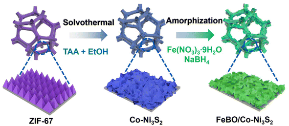
The sequential growth process of crystalline amorphous FeBO/Co-Ni3S2 nanosheet arrays is depicted in Scheme 1. First, Zeolitic imidazolate framework-67 (ZIF-67) was directly and uniformly grown on the NF surface using 2-methylimidazole (2-MIM) as the ligand and Co(NO3)2 as the cobalt precursor using the earlier recipe.34 Fig. S1† illustrates the field emission scanning electron microscope (FE-SEM) images of the ZIF-67 on the NF with a uniform and smooth nanotriangle structure and a thickness of approximately 260 nm. A solvothermal sulfidation process is used to produce Co-Ni3S2 nanosheets. During this process, thioacetamide (TAA) releases a lot of S2− into the solution during the whole reaction process under solvothermal conditions of 120 °C in ethanol. S2− can oxidatively etch ZIF-67 and NF, producing Co ions and Ni ions, and finally forming Co-Ni3S2. Here, the NF is used not only as a source of Ni, but also as a conductive substrate. Finally, ferric nitrate (Fe(NO3)3) was borated by NaBH4 to form a FeBO/Co-Ni3S2 electrocatalyst. Detailed experimental procedure is given in the ESI.†The structural evolution from pure ZIF-67 to Co-Ni3S2 and FeBO/Co-Ni3S2 nanosheets was elucidated using X-ray diffraction (XRD) patterns. The XRD pattern of ZIF-67 is consistent with the literature,35 confirming its successful preparation (Fig. S2†). After the sulfuration reaction, as shown in Fig. 1a, in addition to the NF peak, diffraction peaks located at 21.9°, 31.2°, 37.9°, 50.0°, and 55.4° are perfectly indexed to the (101) (110) (003) (211) and (300) planes of Ni3S2 (PDF#44-1418). There is no diffraction peak related to ZIF-67 in the XRD pattern of the above sample, indicating that the ZIF-67 supported on NF has been completely converted into the corresponding Co-Ni3S2. This is similar to the XRD pattern of pure Ni3S2 prepared by direct solvothermal sulfidation of clean NF substrate. It is noteworthy that the (003) and (006) diffraction peaks of Co-Ni3S2 slightly shift to lower angles compared with those of pristine Ni3S2 (Fig. S3†), indicating that Co ion doping leads to lattice expansion of nickel sulfide, which will promote the phase transformation during electrochemical reconstruction.36 The XRD pattern of FeBO/Co-Ni3S2 is almost the same as that of Co-Ni3S2, indicating that FeBO mainly exists in disordered and amorphous phases. Furthermore, this was also demonstrated by FeBO synthesized on pure NF, which showed an amorphous phase (Fig. S4†), which is consistent with previously reported research results.37 The above results illustrate the formation of amorphous–crystalline FeBO/Co-Ni3S2 heterostructure on NF. Furthermore, Fig. 1b shows their Raman spectra. The vibration of Ni3S2 causes the appearance of Raman characteristic peaks at 233, 312, 331, and 358 cm−1 for FeBO/Co-Ni3S2, Co-Ni3S2, and Ni3S2.38,39 It is worth noting that compared with Ni3S2, the peak of sample Co-Ni3S2 moves to the low wavenumber direction. This is because the doping of Co causes the crystal to expand. However, for FeBO/Co-Ni3S2, the Raman peak at about 358 cm−1 becomes broader and the wavenumber is lower (Fig. S5†). This is because of the strong heterointerface interaction between FeBO and Ni3S2.40,41 The Raman phenomenon is consistent with the XRD results above, demonstrating that ion doping and heterojunction play an important role in regulating the local environment in the sample via electronic interactions, resulting in structural flexibility and potential performance improvements.42 The surface functional groups of these materials are further investigated using Fourier transform infrared spectroscopy (FT-IR) in Fig. 1c. The C–H vibration (1364 cm−1) and the O–H bending vibration (3340 cm−1 and 1630 cm−1) can be assigned to several different areas.43 In addition, the asymmetric and symmetric vibrations of M–S are located at 1057 cm−1 and 642 cm−1 respectively.44
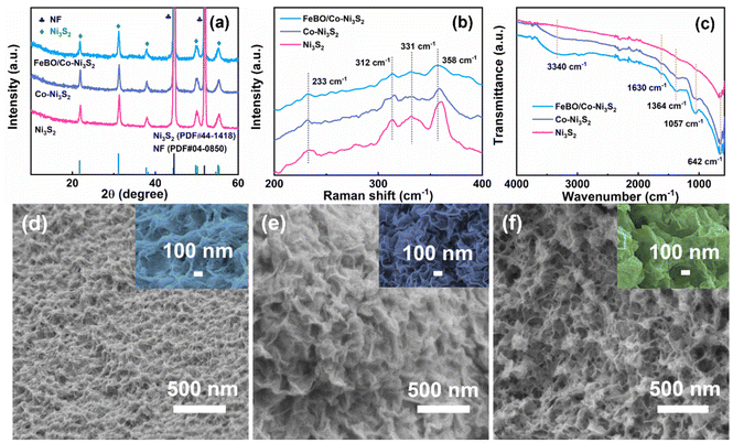 | ||
| Fig. 1 (a) XRD patterns, (b) Raman, and (c)FT-IR spectra of FeBO/Co-Ni3S2, Co-Ni3S2, and Ni3S2 samples. SEM images of (d) Ni3S2, (e) Co-Ni3S2, and (f) FeBO/Co-Ni3S2. | ||
Furthermore, SEM images show the morphological characteristics of Ni3S2, Co-Ni3S2, and FeBO/Co-Ni3S2 (Fig. 1d–f, and Fig. S6†). After the NF sulfidation process, Ni3S2 shows the morphology of wrinkled nanosheets growing on the NF surface. It is noteworthy that Co-Ni3S2 shows more wrinkled nanosheets than Ni3S2, suggesting that the introduction of Co and the use of ZIF as a template aid in the formation of nanosheet structures, exposing large active sites and accelerating the electron transfer process. The SEM image of FeBO/Co-Ni3S2 is shown in Fig. 1f. Some small nanosheets appear on the surface of 2D Co-Ni3S2 nanosheets, eventually forming a rough and irregular layered nanosheet structure. The transmission electron microscope (TEM) image of FeBO/Co-Ni3S2 also shows a rough and irregular nanosheet morphology (Fig. 2a and b). In addition, the structure of FeBO/Co-Ni3S2 was further confirmed by high-resolution TEM (HR-TEM). The HR-TEM image (Fig. 2c) shows an interface, with no obvious crystal lattice in area 1, indicating an amorphous form. However, the HR-TEM image of area 2 exhibits obvious lattice fringes throughout the view, and the lattice fringes with an interplanar spacing of 0.29 nm are assigned to the (110) crystal planes of Ni3S2, and the corresponding selected area electron diffraction (SAED) pattern shows obvious diffraction spots (Fig. 2d), which proves that Ni3S2 exists in crystalline form.
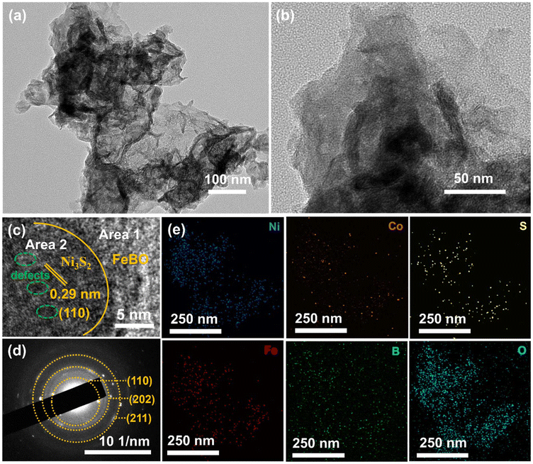 | ||
| Fig. 2 (a and b) TEM image, (c) HR-TEM image, (d) SAED, and (e) EDS elemental mapping of Ni, Co, S, Fe, B, and O elementals for FeBO/Co-Ni3S2. | ||
It is noteworthy that some lattice defects can be discovered in the Ni3S2 lattice, which could be caused by the presence of Co atoms, potentially offering extra active sites.25 In addition, Fig. S7† clearly shows the existence of multiple amorphous–crystalline interfaces, which can further prove the synthesis of amorphous–crystalline nanostructures. Energy-dispersive X-ray spectroscopy (EDS) mapping analysis further confirmed the coupling between amorphous FeBO and crystalline Co-Ni3S2, where Fe, Co, Ni, S, B, and O are orderly distributed throughout the nanosheet (Fig. 2e). The combination of EDS and HR-TEM analysis showed that amorphous FeBO and crystalline Co-Ni3S2 formed a heterogeneous interface.
The surface composition and chemical state of the crystalline–amorphous heterostructure were studied by X-ray photoelectron spectroscopy (XPS). The XPS survey spectrum of FeBO/Co-Ni3S2 verifies the presence of Fe, Co, Ni, S, B, and O elements (Fig. S8†). Fig. 3a displays the deconvoluted spectrum of Ni 2p. The Ni2+/Ni3+ content ratios for FeBO/Co-Ni3S2 and Co-Ni3S2 are 2.24![[thin space (1/6-em)]](https://www.rsc.org/images/entities/char_2009.gif) :
:![[thin space (1/6-em)]](https://www.rsc.org/images/entities/char_2009.gif) 1 and 1.46
1 and 1.46![[thin space (1/6-em)]](https://www.rsc.org/images/entities/char_2009.gif) :
:![[thin space (1/6-em)]](https://www.rsc.org/images/entities/char_2009.gif) 1, respectively. The Ni 2p3/2 and Ni 2p1/2 peaks of FeBO/Co-Ni3S2 are negatively shifted compared to Co-Ni3S2. It is evident from the rise in the concentration of Ni2+ and the fall in binding energy that Co-Ni3S2 serves as an electron acceptor in the heterostructure.45 In addition, in the Co 2p XPS spectrum (Fig. 3b), the peaks at 780.9 and 783.5 eV are attributed to Co3+ and Co2+ in FeBO/Co-Ni3S2,46 respectively. Compared with Co-Ni3S2, the binding energy of Co3+ in FeBO/Co-Ni3S2 is negatively shifted by 0.3 eV, revealing the electron donating properties of FeBO in the heterostructure. Furthermore, the S 2p XPS spectrum of FeBO/Co-Ni3S2 can be attributed to Ni–S bond and SO42−, among which SO42− may be caused by oxidation of the catalyst when exposed to air.22 The XPS peak corresponds to Ni–S bond shifts to a lower binding energy in comparison to Co-Ni3S2, demonstrating the electron-accepting behavior of Co-Ni3S2 in the FeBO/Co-Ni3S2 structure (Fig. 3c). In nanostructured systems, interface electrons adjust the distribution of electron clouds through donor/acceptor characteristics, making them more suitable for catalytic reactions.47 The two peaks in the high-resolution Fe 2p spectrum, Fig. 3d, have binding energies of 714 and 724 eV, respectively, and can be attributed to Fe 2p3/2 and Fe 2p1/2. The peaks at 191 and 192 eV in the B 1s region (Fig. 3e) represent the Fe–B–O and B–O signals in FeBO.48 The O peaks could deconvolute into two major peaks at 531.8 and 530.9 eV, corresponding to the Fe–O–B and Fe–O–Fe bond in FeBO/Co-Ni3S2, respectively (Fig. 3f).49 XPS analysis confirms that there is electron transfer between the crystalline Co-Ni3S2 and amorphous FeBO phases at the interface. This regulated electronic structure has a direct role in enhancing the activity of interfacial active sites.
1, respectively. The Ni 2p3/2 and Ni 2p1/2 peaks of FeBO/Co-Ni3S2 are negatively shifted compared to Co-Ni3S2. It is evident from the rise in the concentration of Ni2+ and the fall in binding energy that Co-Ni3S2 serves as an electron acceptor in the heterostructure.45 In addition, in the Co 2p XPS spectrum (Fig. 3b), the peaks at 780.9 and 783.5 eV are attributed to Co3+ and Co2+ in FeBO/Co-Ni3S2,46 respectively. Compared with Co-Ni3S2, the binding energy of Co3+ in FeBO/Co-Ni3S2 is negatively shifted by 0.3 eV, revealing the electron donating properties of FeBO in the heterostructure. Furthermore, the S 2p XPS spectrum of FeBO/Co-Ni3S2 can be attributed to Ni–S bond and SO42−, among which SO42− may be caused by oxidation of the catalyst when exposed to air.22 The XPS peak corresponds to Ni–S bond shifts to a lower binding energy in comparison to Co-Ni3S2, demonstrating the electron-accepting behavior of Co-Ni3S2 in the FeBO/Co-Ni3S2 structure (Fig. 3c). In nanostructured systems, interface electrons adjust the distribution of electron clouds through donor/acceptor characteristics, making them more suitable for catalytic reactions.47 The two peaks in the high-resolution Fe 2p spectrum, Fig. 3d, have binding energies of 714 and 724 eV, respectively, and can be attributed to Fe 2p3/2 and Fe 2p1/2. The peaks at 191 and 192 eV in the B 1s region (Fig. 3e) represent the Fe–B–O and B–O signals in FeBO.48 The O peaks could deconvolute into two major peaks at 531.8 and 530.9 eV, corresponding to the Fe–O–B and Fe–O–Fe bond in FeBO/Co-Ni3S2, respectively (Fig. 3f).49 XPS analysis confirms that there is electron transfer between the crystalline Co-Ni3S2 and amorphous FeBO phases at the interface. This regulated electronic structure has a direct role in enhancing the activity of interfacial active sites.
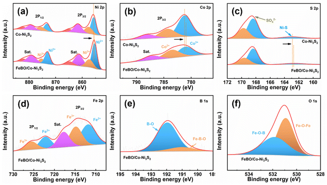 | ||
| Fig. 3 XPS spectra (a) Ni 2p; (b) Co 2p; (c) S 2p of Co-Ni3S2 and FeBO/Co-Ni3S2; (d) Fe 2p; (e) B 1s and (f) O 1s of FeBO/Co-Ni3S2. | ||
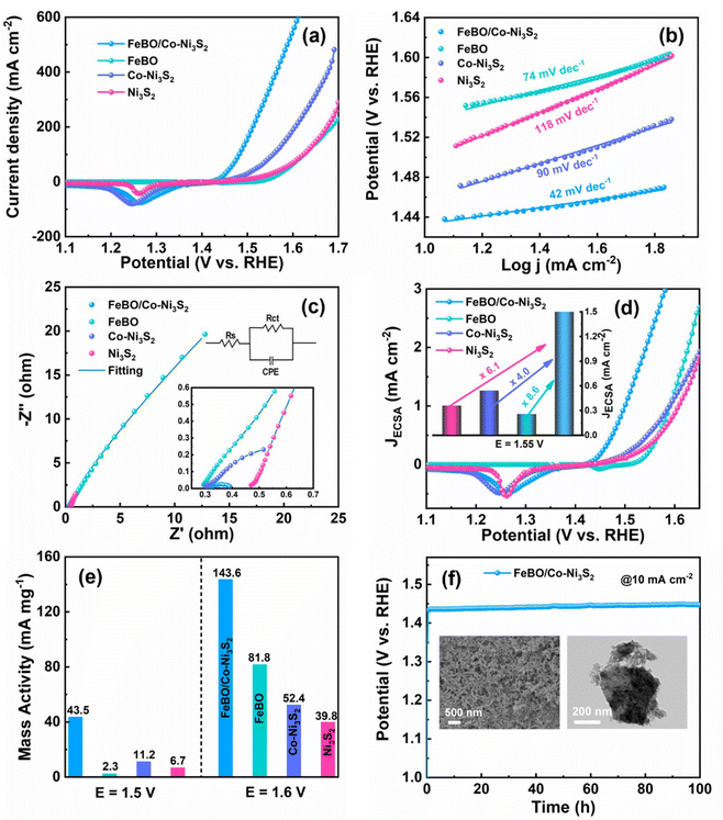
To reveal the effect of crystalline–amorphous structures on OER activity, a series of materials were tested for their electrocatalytic activity towards OER using a conventional three-electrode system in 1 M KOH electrolyte. A commercial RuO2 electrode was also tested as a comparison. FeBO/Co-Ni3S2, which required an overpotential of 205 mV to produce a current density of 10 mA cm−2, showed excellent OER catalytic performance. This overpotential is considerably lower than those of FeBO (317 mV), Co-Ni3S2 (234 mV), Ni3S2 (268 mV), ZIF-67 (276 mV), NF (354 mV), and RuO2 (322 mV) (Fig. 4a and S9†). Meanwhile, the overpotentials at current densities of 100 and 200 mA cm−2 have been compared (Fig. S10†). FeBO/Co-Ni3S2 is shown to have the lowest overpotential in all current density ranges. To better understand reaction kinetic, we deduced the Tafel slope from the LSV curves linked to OER kinetics. The Tafel slope of FeBO/Co-Ni3S2 is 42 mV dec−1, which is much lower than that of FeBO (74 mV dec−1), Co-Ni3S2 (90 mV dec−1), Ni3S2 (118 mV dec−1), ZIF-67 (136 mV dec−1), RuO2 (107 mV dec−1), and NF (111 mV dec−1), which indicates that FeBO/Co-Ni3S2 has faster reaction kinetics during the OER process (Fig. 4b and S11†). Furthermore, FeBO/Co-Ni3S2 outperforms other recently reported catalysts in terms of OER performance (Table S1†).
To study the origin of the enhanced OER activity of FeBO/Co-Ni3S2, electrochemical impedance spectroscopy (EIS) was performed to illustrate the electron transfer ability of FeBO/Co-Ni3S2. The diameter of the semicircle shows that the charge transfer resistance (Rct) of FeBO/Co-Ni3S2 (0.108 Ω) is significantly lower than that of FeBO (163 Ω), Co-Ni3S2 (1.14 Ω) and Ni3S2 (20.3 Ω), indicating that heterostructure can improve the conductivity of the catalyst to reduce the Rct value (Fig. 4c and Table S2†). In addition, electrochemical surface area (ECSA) calculations were performed, and the ECSA value is a key indicator reflecting catalytic activity. ECSA of FeBO/Co-Ni3S2, FeBO, Co-Ni3S2, and Ni3S2 was investigated from the electrochemical double-layer capacitance (Cdl), and the Cdl of the electrode was determined by converting the cyclic voltammograms (CVs) in the non-faradaic range (Fig. S12†). FeBO/Co-Ni3S2 (6.3 mF cm−2; ECSA = 157.5 cm2) has a Cdl that is greater than that of Ni3S2 (3.2 mF cm−2; ECSA = 80.0 cm2) and FeBO (2.1 mF cm−2; ECSA = 52.5 cm2), but lower than that of Co-Ni3S2 (6.6 mF cm−2; ECSA = 165 cm2) (Fig. S13†). It is worth noting that the ECSA of FeBO/Co-Ni3S2 is not the highest. Since the LSV curve is usually used to characterize the current response at different potentials and Cdl represents the ECSA exposed by the catalyst, there is not always a positive correlation between the electrocatalytic performance and the ECSA.50 The high OER catalytic activity of FeBO/Co-Ni3S2 is more likely to be the result of intrinsic activity than the result of ECSA.51 Thus, the most effective configuration for optimal OER performance is one with a larger ECSA and higher intrinsic activity.
The ECSA-normalized LSV curve is more accurate in determining the intrinsic activity of the catalyst and ruling out geometric effects because ECSA will change the current density during the catalysis process.52 The FeBO/Co-Ni3S2 shows a smaller overpotential than the other electrocatalysts throughout the current range from the ECSA-normalized LSV curves (Fig. 4d), implying a higher intrinsic per-site activity of the FeBO/Co-Ni3S2 heterojunction nanosheets. For FeBO/Co-Ni3S2, the normalized current density is 2.169 mA cm−2 at 1.55 V, which is 8.6, 4.0 and 6.1 times that of FeBO (0.251 mA cm−2) and Co-Ni3S2 (0.537 mA cm−2), and Ni3S2 (0.354 mA cm−2), respectively, proving its high intrinsic activity (inset: Fig. 4d). In addition, at an overpotential of 270 mV, the mass activity (MA) FeBO/Co-Ni3S2 is approximately 18, 4 and 6 times higher than those of FeBO, Co-Ni3S2, and Ni3S2 respectively (Fig. 4e and S14†). Even at larger potentials, its MA far exceeds that of the comparative catalyst, again validating the increase in its intrinsic activity. Furthermore, to explore the stability of FeBO/Co-Ni3S2, the long-term chronopotentiometry (CP) stability is tested at a current density of 10 mA cm−2. FeBO/Co-Ni3S2 exhibits excellent stability with a stable potential within 100 h (Fig. 4f). The LSV curves before and after long-term stability nearly coincide (Fig. S15†), further revealing the excellent durability of FeBO/Co-Ni3S2.
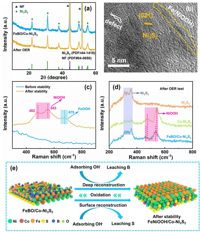
During electrocatalysis, the phases that emerge from component reconstruction are considered to be the true active sites due to the leaching of original elements and the formation of metal (oxygen) hydroxides on the catalyst surface. However, the mechanism of the reconstruction process remains unclear, and this issue is explored through various characterizations. After the OER stability test, the catalyst was characterized by XRD, and it was found that its diffraction peak was basically consistent with that before the test (Fig. 5a), which means that Co-Ni3S2 only underwent surface reconstruction, while its interior did not change. The SEM image still shows the structure of the nanosheets (inset Fig. 4f). The HR-TEM image in Fig. 5b shows that the lattice part corresponds to Ni3S2 and is adjacent to the amorphous layer. EDS mapping showed that the S and B elements are significantly weakened, and the O element is stronger for FeBO/Co-Ni3S2, suggesting the loss of S and B elements and the enhanced oxidation process during the OER process (Fig. S16†). XPS analysis further reflects the surface chemical states of FeBO/Co-Ni3S2 before and after OER stability. The XPS signals of the Ni 2p and Fe 2p after the stability test (Fig. S17a and S17b†) tend to move in the direction of high binding energy, indicating the formation of high-valence Fe and Ni. The rise in transition metal valence number is thought to accelerate the multi-electron transfer mechanism involved in water oxidation, resulting in more active OER catalysts with superior performance.15 In addition, the XPS peak intensity of S and B decreased after the OER test (Fig. S17c and S17d†), among which the B element decreased the most, which can be confirmed by comparing with Fig. 3 before the test. This change can be attributed to the leaching of B and the gradual transformation of FeBO metal boride into FeOOH, which is also proved by Raman.
To gain a deeper understanding of the structural changes of the FeBO/Co-Ni3S2 catalyst under OER conditions, electrochemical Raman spectroscopy was used to study the catalyst at different reaction stages. For FeBO/Co-Ni3S2, when the voltage was applied for a period, a pair of new peaks appeared at 462 and 535 cm−1, which were attributed to the Ni–O vibration in NiOOH. When the voltage was continued to be applied, another new peak appeared at 683 cm−1, which was attributed to the Fe–O vibration of FeOOH (Fig. 5c and Fig. S18†).53 The excellent OER performance of the newly formed NiFeOOH species may be attributed to the transformation of Ni and Fe into higher valence states and the increased OH− affinity in comparison to Ni sites. At the same time, a bimetallic oxyhydroxide film was formed on the surface of Co-Ni3S2 nanosheets, and the synergistic effect of Fe and Ni improved the OER performance.54 Overall, the electrode exhibits excellent durability because the newly formed NiFeOOH phase is uniformly distributed on the electrode surface. In addition, to correlate Co doping and FeBO with the electrochemical reconstruction process, we conducted Raman spectroscopy studies on the catalyst during the OER process to gain insight into the dynamic reconstruction process. For Co-Ni3S2, a pair of peaks at 476 and 543 cm−1 were observed in the Raman spectrum after the OER reaction (Fig. S19†), which was attributed to the Ni–O vibration in NiOOH.55 The Raman results show that when part of Ni3S2 is dissolved, the Ni–S bond breaks, thereby generating Ni2+ in the solution. At the same time, the dissolved Ni ions quickly combine with OH− ions to generate NiOOH. Therefore, when voltage is applied, Co-Ni3S2 is oxidized in KOH and converted into NiOOH. In contrast, when pressure is applied, the Raman characteristic peaks of Ni3S2 still exist, and no other peaks are shown, indicating that no NiOOH is generated after the OER reaction. Obviously, the above results indicate that Co doping promotes the formation of active phase NiOOH species. Furthermore, there is a negative shift observed in the NiOOH peak in the FeBO/Co-Ni3S2 sample when compared to the peak of Co-Ni3S2 (Fig. 5d). This suggests that the Ni–O bond length in the NiOOH in the FeBO/Co-Ni3S2 sample is longer than that of the Co-Ni3S2 sample. This is due to the fact that FeBO inhibits S from dissolving during the OER process.15 Longer Ni–O bonds might be linked to a more open NiOOH lattice, which would facilitate active site formation and transportation, enhancing OER activity.56,57 In summary, FeBO serves as a catalytically active material to form the amorphous FeOOH phase, thereby forming NiFeOOH species and further improving the catalytic activity and durability of the catalyst. Based on the above analysis, Fig. 5e details the accelerated reaction kinetics coupling crystalline Co-Ni3S2 with amorphous FeBO. The FeBO outer layer of FeBO/Co-Ni3S2 was oxidized during the test process by continuously absorbing hydroxyl groups in the electrolyte and then converted into highly active FeOOH species as a large number of B atoms were leached out. At the same time, Co doping also caused the surface reconstruction of Co-Ni3S2, which in turn resulted in the loss of the S element. This was verified by XPS analysis before and after OER stabilization. Therefore, highly active site NiFeOOH species are generated as the reaction proceeds. Therefore, the heterojunction structure electrocatalyst composed of crystalline Co-Ni3S2 and amorphous FeBO exhibits excellent OER activity due to the following synergistic effects: (1) the doped Co cations promote faster reconstruction of the Ni3S2 surface, leading to the formation of wrinkled nanosheets with abundant active sites (NiOOH); (2) deep reconstruction results in self-optimized electrocatalysts with short electron transfer pathways, and fully exposed internal active sites; (3) complete amorphous phase reconstruction can greatly enhance charge distribution and electrochemical responsiveness and stability of the crystal–amorphous (FeBO/Co-Ni3S2) coupling structure.
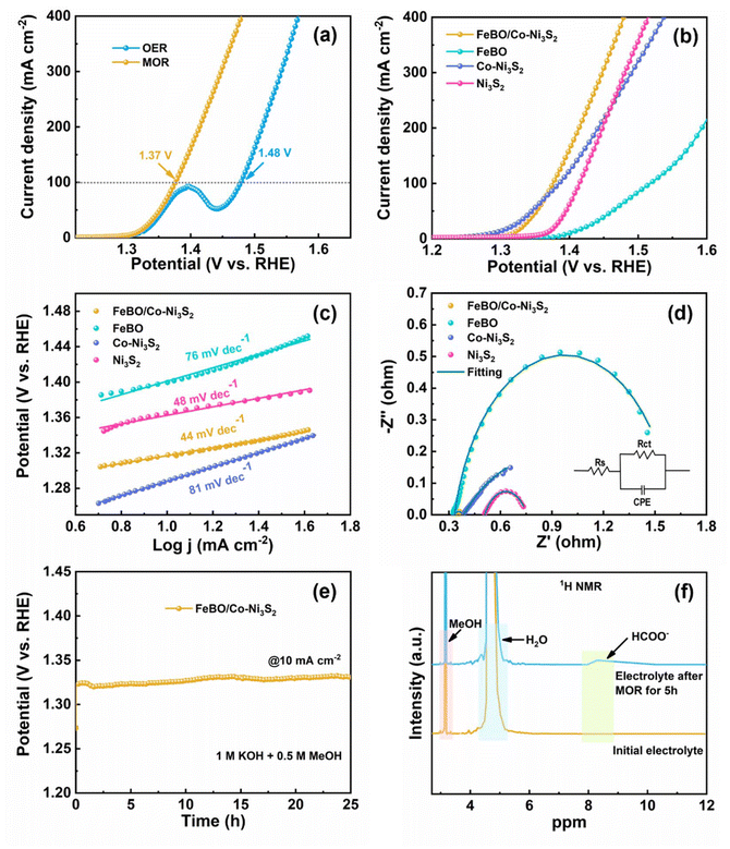
Inspired by the excellent OER activity, FeBO/Co-Ni3S2 was further studied with a mixed solution of 1 M KOH and 0.5 M methanol as the electrolyte to study the MOR performance of the catalyst. As shown in Fig. 6a, the LSV curve shows that FeBO/Co-Ni3S2 requires a low potential of 1.37 V to achieve a MOR current density of 100 mA cm−2, verifying that the anodizing potential can be significantly reduced. In contrast, the same conditions were used to measure the MOR catalytic activities of Ni3S2, Co-Ni3S2, and FeBO. The FeBO/Co-Ni3S2 electrode further demonstrates the advantages of crystalline and amorphous heterostructures for MOR performance, requiring only 1.37 V at 100 mA cm−2, which is less than Ni3S2 (1.41 V), Co-Ni3S2 (1.39 V), and FeBO (1.52 V) (Fig. 6b). The corresponding Tafel slopes of catalysts were used to investigate the MOR kinetics. The Tafel slope of FeBO/Co-Ni3S2 is 44 mV dec−1 (Fig. 6c), which is the smallest compared to FeBO (76 mV dec−1), Co-Ni3S2 (81 mV dec−1), and Ni3S2 (48 mV dec−1), indicating faster reaction kinetics. EIS measurements further supported the explanation for the superior activity of the FeBO/Co-Ni3S2 electrode (Fig. 6d and Table S3†), with the radius of the semicircle representing the Rct, with lower values corresponding to faster rates. The FeBO/Co-Ni3S2 sample has the lowest Rct of all the samples, which indicates that the charge-transfer process between the electrode and electrolyte solution is facilitated at their biphasic interface. To further understand the prominent MOR activities, Cdl values were used to compare ECSA based on CV at different scan rates (Fig. S20†). In addition, the stability of FeBO/Co-Ni3S2 was tested by CP measurements. The FeBO/Co-Ni3S2 catalyst also exhibited excellent long-term stability with 25 h for MOR electrocatalysis at 10 mA cm−2, as shown in Fig. 6e, which revealed outstanding durability.
As shown in Fig. 6f, 1H NMR measurements were used to analyse the anode products during the stability test. Here, the catalytic conversion of methanol to formate at the anode is confirmed by a new peak detected at 8.28 ppm (electrolyte after 5 h of MOR) that corresponds to HCOO−.58 We characterized the morphology and structure before and after the stability testing. The nanosheet and structure can still be observed in the FT-SEM and XRD images after the MOR stability tests (Fig. S21 and S22†), proving the stability of the heterostructure.
We further evaluated the HER activity of FeBO/Co-Ni3S2 catalyst in 1 M KOH electrolyte. As shown in Fig. S23a,† the FeBO/Co-Ni3S2 only requires an overpotential of 177 mV to produce a current density of 10 mA cm−2, which is lower than that of FeBO (211 mV), Co-Ni3S2 (187 mV) and Ni3S2 (229 mV). Notably, the catalyst exhibited similar HER activity in 1 M KOH with or without 0.5 M methanol, indicating that the presence of methanol does not affect the HER activity (Fig. S23b†). The enhanced HER activity can be further confirmed by comparing the Tafel slopes of the catalysts. FeBO/Co-Ni3S2 exhibited a low value of 114 mV dec−1, which was smaller than those FeBO, Co-Ni3S2, and Ni3S2 (Fig. S23c†), further demonstrating the important role of hetero-interface modulation in promoting intrinsic catalytic kinetics. The HER stability of FeBO/Co-Ni3S2 was verified by multi-step CP tests with current densities ranging from −10 to −100 mA cm−2 (Fig. S23d and S23e†). Interestingly, the voltage also increases with the increase in current density and remains stable in every step of the test, which means that FeBO/Co-Ni3S2 has good conductivity and fast mass transfer during the HER process. Additionally, an investigation was conducted into the long-term stability of FeBO/Co-Ni3S2 at −10 mA cm−2. Fig. S23f† demonstrates the remarkable HER durability of FeBO/Co-Ni3S2, as the current density did not change after testing for nearly 100 h.
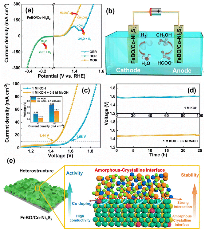
The catalyst has excellent OER, MOR and HER (Fig. 7a), prompting us to further investigate its overall water splitting and methanol splitting by constructing a two-electrode system with FeBO/Co-Ni3S2 as the cathode and anode (Fig. 7b). In addition, compared with MOR, the occurrence of OER requires overcoming a higher energy barrier, so using MOR as an anode reaction will significantly reduce energy consumption. As shown in Fig. 7c, the water and methanol electrolysis systems, achieved a current density of 10 mA cm−2 at 1.58 and 1.44 V, respectively. Compared with water splitting, the FeBO/Co-Ni3S2 catalyst has a lower cell potential for methanol electrolysis in alkaline media at the entire current density, thus exhibiting excellent methanol electrocatalytic performance (inset: Fig. 7c). Compared with recently reported bifunctional electrocatalysts, it has better water or methanol electrolysis properties (Table S4†). Impressively, the electrolytic system assembled from FeBO/Co-Ni3S2 also showed very good durability (Fig. 7d). Maintaining a consistent current density of 10 mA cm−2, the cell voltage in 1 M KOH and 1 M KOH + 0.5 M methanol demonstrated a minimal increase in reaction at 100 and 25 h, respectively. In addition, the H2 yield of the FeBO/Co-Ni3S2 electrocatalyst was calculated. The H2 yield collected at a current density of 100 mA cm−2 was ∼93% (Fig. S24, S25, and Table S5†). Overall, the enhancement mechanism of the FeBO/Co-Ni3S2 heterostructure is depicted in Fig. 7e, and the superior performance in the alkaline electrochemical hydrogen production process can be attributed to the following factors: (1) amorphous FeBO-coated crystalline Co-Ni3S2 provides both high electrical conductivity and higher intrinsic activity. (2) The composition and electronic structure of the prepared electrocatalyst, particularly the high-valent metal Ni and Fe active sites, are regulated by the synergistic effect of Co-Ni3S2 and FeBO on the coupling interface, which in turn affects the electrocatalytic activity overall. (3) Amorphous FeBO can be transformed into FeOOH, which surrounds the crystalline Ni3S2 phase, forming dual active sites Ni/FeOOH with NiOOH; the newly formed phase serves as an active site, reducing the corrosion of Ni3S2 during the catalytic electrolysis process, thereby enhancing the durability of the catalyst, which can be verified from Fig. 5. Overall, this amorphous–crystalline (FeBO/Co-Ni3S2) composite structure can substantially improve charge distribution, electrochemical performance, and electrochemical responsiveness and stability upon reconfiguration of the amorphous phase.
3. Conclusions
In summary, an effective strategy was developed to prepare highly active bifunctional electrocatalysts via a self-reconstruction process of amorphous–crystalline heterostructured FeBO/Co-Ni3S2 electrocatalysts composed of cation doping with morphology control and interface engineering. The reasons for its excellent performance are as follows: (a) the Co-Ni3S2 electrocatalyst was synthesized via a self-derivation substrate without any mechanical binder, which enables strong adhesion between the catalyst and the substrate and achieves ultra-long durability in water and methanol electrolysis; (b) excellent metal properties lead to ultra-high conductivity of FeBO/Co-Ni3S2, which is beneficial to charge transfer reactions; (c) at the amorphous crystal interface, FeBO is converted into FeOOH and forms Fe/NiOOH with NiOOH, changing the electronic structure and maximizing the adsorption capacity of active substances. The FeBO/Co-Ni3S2 heterostructure demonstrates stable H2 production and effective, potent electrocatalytic activity in methanol and water electrolysis. With small voltages of 1.44 and 1.58 V (at 10 mA cm−2) for methanol and water electrolysis. Furthermore, the voltage decay was negligible after 25 and 100 h operation at 10 mA cm−2 current density. Overall, this work provides a highly active and stable transition metal-based hydrogen evolution material, which will inspire catalyst design in other energy systems by creating and combining multiple optimization strategies.Data availability
The data supporting the findings of this study can be found in this article or in ESI.†Conflicts of interest
The author states no conflict of interest.Acknowledgements
This work was supported by Priority Research Centers Program through the National Research Foundation of Korea (NRF) funded by the Ministry of Education, Science and Technology (2018R1A6A1A03024334). This work was supported by the National Research Foundation of Korea (NRF) grant funded by the Korea government (MSIT) (No. 2022R1A2C2007219).References
- A. Ganguly, R. J. McGlynn, A. Boies, P. Maguire, D. Mariotti and S. Chakrabarti, ACS Appl. Mater. Interfaces, 2024, 16, 12339–12352 CrossRef CAS PubMed.
- S. S. Roy, R. Madhu, K. Bera, S. Nagappan, H. N. Dhandapani, A. D. T. De and S. Kundu, ACS Appl. Mater. Interfaces, 2024, 16, 5965–5976 CrossRef.
- J. Ding, H. Yang, H. Zhang, Z. Wang, Q. Liu, L. Feng, G. Hu, J. Luo and X. Liu, Int. J. Hydrogen Energy, 2024, 53, 318–324 CrossRef CAS.
- N. K. Shrestha, S. A. Patil, J. Han, S. Cho, A. I. Inamdar, H. Kim and H. Im, J. Mater. Chem. A, 2022, 10, 8989–9000 RSC.
- T. Zhao, D. Z. Zhong, L. Tian, G. Y. Hao, G. Liu, J. P. Li and Q. Zhao, J. Colloid Interface Sci., 2023, 634, 630–641 CrossRef CAS PubMed.
- W. Liu, W. Liu, T. Hou, J. Ding, Z. Wang, R. Yin, X. San, L. Feng, J. Luo and X. Liu, Nano Res., 2024, 17, 4797 CrossRef CAS.
- X. F. Wei, Y. Li, L. S. Chen and J. L. Shi, Angew. Chem., Int. Ed., 2021, 60, 3148–3155 CrossRef CAS PubMed.
- J. X. Dang, G. M. Chen, B. E. Yuan, F. Y. Liu, Q. Wang, F. Wang, H. Miao and J. L. Yuan, Nanoscale, 2024, 16, 4710–4723 RSC.
- D. R. Palo, R. A. Dagle and J. D. Holladay, Chem. Rev., 2007, 107, 3992–4021 CrossRef CAS PubMed.
- D. D. Liu, Z. Y. Wu, J. J. Liu, H. F. Gu, Y. Li, X. Y. Li, S. Liu, S. E. Liu and J. T. Zhang, Small, 2023, 19, 2207235 CrossRef CAS.
- Q. Q. Zhao, B. Zhao, X. Long, R. F. Feng, M. Shakouri, A. Paterson, Q. F. Xiao, Y. Zhang, X. Z. Fu and J. L. Luo, Nano-Micro Lett., 2024, 16, 1–17 CrossRef.
- L. Y. Zeng, K. A. Sun, X. B. Wang, Y. Q. Liu, Y. Pan, Z. Liu, D. W. Cao, Y. Song, S. H. Liu and C. G. Liu, Nano Energy, 2018, 51, 26–36 CrossRef CAS.
- X. Zhou, Y. X. Mo, F. Yu, L. L. Liao, X. R. Yong, F. M. Zhang, D. Y. Li, Q. Zhou, T. Sheng and H. Q. Zhou, Adv. Funct. Mater., 2023, 33, 2209465 CrossRef CAS.
- S. S. Huang, Q. Zhang, P. J. Xin, J. Zhang, Q. C. Chen, J. Fu, Z. Q. Jin, Q. Wang and Z. J. Hu, Small, 2022, 18, 2106841 CrossRef CAS.
- D. R. Li, W. J. Wan, Z. W. Wang, H. Y. Wu, S. X. Wu, T. Jiang, G. X. Cai, C. Z. Jiang and F. Ren, Adv. Energy Mater., 2022, 12, 2201913 CrossRef CAS.
- T. Y. Kou, T. Smart, B. Yao, I. Chen, D. Thota, Y. Ping and Y. Li, Adv. Energy Mater., 2018, 8, 1703538 CrossRef.
- X. Y. Wang, X. Yu, S. Wu, P. Y. He, F. Qin, Y. K. Yao, J. L. Bai, G. J. Yuan and L. L. Ren, ACS Appl. Mater. Interfaces, 2023, 15, 15533–15544 CrossRef CAS.
- B. Tang, Y. Lv, J. N. Du, Y. Dai, S. Y. Pan, Y. Xie and J. L. Zou, ACS Sustainable Chem. Eng., 2019, 7, 11101–11109 CrossRef CAS.
- G. Zhang, Y. S. Feng, W. T. Lu, D. He, C. Y. Wang, Y. K. Li, X. Y. Wang and F. F. Cao, ACS Catal., 2018, 8, 5431–5441 CrossRef CAS.
- L. Z. Sun, Z. Y. Zhou, Y. A. Xie, J. G. Zheng, X. Pan, L. N. Li and G. H. Zhao, Adv. Funct. Mater., 2023, 33, 2301884 CrossRef CAS.
- X. Tong, Y. Li, N. Pang, Y. H. Qu, C. H. Yan, D. Y. Xiong, S. H. Xu, L. W. Wang and P. K. Chu, Chem. Eng. J., 2021, 425, 130455 CrossRef CAS.
- Y. X. Feng, R. L. Smith, J. Y. Fu and X. H. Qi, Green Chem., 2023, 25, 8698–8705 RSC.
- Z. H. Kou, K. X. Wang, Z. B. Liu, L. B. Zeng, Z. J. Li, B. Yang, L. C. Lei, C. Yuan and Y. Hou, Small Struct., 2022, 3, 2100153 CrossRef CAS.
- C. Qin, S. Chen, H. Gomaa, M. Shenashen, S. El-Safty, Q. Liu, C. An, X. Liu, Q. Deng and N. Hu, Acta Phys. -Chim. Sin., 2024, 40, 2307059 Search PubMed.
- F. Zheng, M. A. Gaikwad, Z. Fang, S. Jang and J. H. Kim, Energy Fuels, 2024, 38, 6290–6299 CrossRef CAS.
- K. X. Wang, Y. Y. Guo, Z. H. Chen, D. H. Wu, S. R. Zhang, B. C. Yang and J. N. Zhang, InfoMat, 2022, 4, e12251 CrossRef CAS.
- S. Anantharaj and S. Noda, Small, 2020, 16, 1905779 CrossRef CAS PubMed.
- J. Wang, L. L. Han, B. L. Huang, Q. Shao, H. L. L. Xin and X. Q. Huang, Nat. Commun., 2019, 10, 5692 CrossRef CAS PubMed.
- J. M. V. Nsanzimana, Y. C. Peng, Y. Y. Xu, L. Thia, C. Wang, B. Y. Xia and X. Wang, Adv. Energy Mater., 2018, 8, 1701475 CrossRef.
- Y. Duan, Z. Y. Yu, S. J. Hu, X. S. Zheng, C. T. Zhang, H. H. Ding, B. C. Hu, Q. Q. Fu, Z. L. Yu, X. Zheng, J. F. Zhu, M. R. Gao and S. H. Yu, Angew. Chem., Int. Ed., 2019, 58, 15772–15777 CrossRef CAS PubMed.
- M. Moloudi, A. Noori, M. S. Rahmanifar, Y. Shabangoli, M. F. El-Kady, N. B. Mohamed, R. B. Kaner and M. F. Mousavi, Adv. Energy Mater., 2023, 13, 2203002 CrossRef CAS.
- T. I. Singh, A. Maibam, D. C. Cha, S. Yoo, R. Babarao, S. U. Lee and S. Lee, Adv. Sci., 2022, 9, 2201311 CrossRef CAS.
- M. Liu, K. Xie, M. D. Nothling, L. H. Zu, S. L. Zhao, D. J. E. Harvie, Q. Fu, P. A. Webley and G. G. Qiao, ACS Cent. Sci., 2021, 7, 671–680 CrossRef CAS PubMed.
- F. Zheng, X. Li, M. A. Gaikwad, S. Jang and J. H. Kim, Surf. Interfaces, 2023, 42, 103407 CrossRef CAS.
- K. Y. Zhu, J. Y. Chen, W. J. Wang, J. W. Liao, J. C. Dong, M. O. L. Chee, N. Wang, P. Dong, P. M. Ajayan, S. P. Gao, J. F. Shen and M. X. Ye, Adv. Funct. Mater., 2020, 30, 2003556 CrossRef CAS.
- J. Nie, J. Shi, T. Huang, M. Xie, Z. Ouyang, M. Xian, G. Huang, H. Wan, W. Hu and W. Huang, Adv. Funct. Mater., 2024, 34, 2314172 CrossRef CAS.
- G. Liu, D. Y. He, R. Yao, Y. Zhao, M. H. Wang, N. Li and J. P. Li, Int. J. Hydrogen Energy, 2018, 43, 6138–6149 CrossRef CAS.
- Q. C. Xu, M. S. Chu, M. M. Liu, J. H. Zhang, H. Jiang and C. Z. Li, Chem. Eng. J., 2021, 411, 128488 CrossRef CAS.
- Z. Cheng, H. Abernathy and M. L. Liu, J. Phys. Chem. C, 2007, 111, 17997–18000 CrossRef CAS.
- Z. P. Wang, S. J. Shen, Z. P. Lin, W. Y. Tao, Q. H. Zhang, F. Q. Meng, L. Gu and W. W. Zhong, Adv. Funct. Mater., 2022, 32, 2112832 CrossRef CAS.
- R. C. Li, P. Y. Kuang, L. X. Wang, H. L. Tang and J. G. Yu, Chem. Eng. J., 2022, 431, 134137 CrossRef CAS.
- Y. Sun, R. Li, X. Chen, J. Wu, Y. Xie, X. Wang, K. Ma, L. Wang, Z. Zhang, Q. Liao, Z. Kang and Y. Zhang, Adv. Energy Mater., 2021, 11, 2003755 CrossRef CAS.
- M. Braglia, I. V. Ferrari, T. Djenizian, S. Kaciulis, P. Soltani, M. L. Di Vona and P. Knauth, ACS Appl. Mater. Interfaces, 2017, 9, 22902–22910 CrossRef CAS PubMed.
- X. P. Wang, L. B. Li, M. Z. Shi, Y. Q. Wang, G. D. Xu, K. Yuan, P. P. Zhu, M. N. Ding and Y. W. Chen, Chem. Sci., 2022, 13, 11639–11647 RSC.
- M. S. Jo, S. Ghosh, S. M. Jeong, Y. C. Kang and J. S. Cho, Nano-Micro Lett., 2019, 11, 1–18 CrossRef PubMed.
- Y. J. Lee and S. K. Park, Small, 2022, 18, 2200586 CrossRef CAS PubMed.
- Y. D. Liu, T. Sakthivel, F. Hu, Y. H. Tian, D. S. Wu, E. H. Ang, H. Liu, S. W. Guo, S. J. Peng and Z. F. Dai, Adv. Energy Mater., 2023, 13, 2203797 CrossRef CAS.
- Q. C. Zhang, J. P. Zhao, Y. C. Wu, J. Li, H. L. Jin, S. Q. Zhao, L. L. Chai, Y. H. Wang, Y. Lei and S. Wang, Small, 2020, 16, 2003342 CrossRef CAS.
- W. N. Zhao, T. Xu, T. Li, Y. K. Wang, H. Liu, J. Z. Feng, S. J. Ding, Z. T. Li and M. B. Wu, Small, 2018, 14, 1802829 CrossRef.
- W. Z. Huang, C. X. Chen, Z. H. Ling, J. T. Li, L. B. Qu, J. X. Zhu, W. Yang, M. M. Wang, K. A. Owusu, L. Qin, L. Zhou and L. Q. Mai, Chem. Eng. J., 2021, 405, 126959 CrossRef CAS.
- W. Z. Huang, J. T. Li, X. B. Liao, R. H. Lu, C. H. Ling, X. Liu, J. S. Meng, L. B. Qu, M. T. Lin, X. F. Hong, X. B. Zhou, S. L. Liu, Y. Zhao, L. Zhou and L. Q. Mai, Adv. Mater., 2022, 34, 2200270 CrossRef CAS PubMed.
- W. Huang, J. Li, X. Liao, R. Lu, C. Ling, X. Liu, J. Meng, L. Qu, M. Lin, X. Hong, X. Zhou, S. Liu, Y. Zhao, L. Zhou and L. Mai, Adv. Mater., 2022, 34, e2200270 CrossRef.
- J. Y. Gao, H. Q. Ma, L. F. Zhang, X. Y. Luo and L. Q. Yu, J. Alloys Compd., 2022, 893, 162244 CrossRef CAS.
- J. Rossmeisl, Z. W. Qu, H. Zhu, G. J. Kroes and J. K. Norskov, J. Electroanal. Chem., 2007, 607, 83–89 CrossRef CAS.
- M. W. Louie and A. T. Bell, J. Am. Chem. Soc., 2013, 135, 12329–12337 CrossRef CAS PubMed.
- O. Diaz-Morales, D. Ferrus-Suspedra and M. T. M. Koper, Chem. Sci., 2016, 7, 2639–2645 RSC.
- D. Friebel, M. W. Louie, M. Bajdich, K. E. Sanwald, Y. Cai, A. M. Wise, M. J. Cheng, D. Sokaras, T. C. Weng, R. Alonso-Mori, R. C. Davis, J. R. Bargar, J. K. Norskov, A. Nilsson and A. T. Bell, J. Am. Chem. Soc., 2015, 137, 1305–1313 CrossRef CAS PubMed.
- A. Sathyaseelan, K. Krishnamoorthy, P. Pazhamalai, N. U. L. Ali and S. J. Kim, J. Mater. Chem. A, 2023, 11, 20712–20723 RSC.
Footnote |
| † Electronic supplementary information (ESI) available. See DOI: https://doi.org/10.1039/d4nr02985b |
| This journal is © The Royal Society of Chemistry 2025 |

