 Open Access Article
Creative Commons Attribution 3.0 Unported Licence
Achievement of visible-light-driven Z-scheme overall water splitting using barium-modified Ta3N5 as a H2-evolving photocatalyst†
Yu
Qi
ab,
Shanshan
Chen
a,
Mingrun
Li
a,
Qian
Ding
ab,
Zheng
Li
ab,
Junyan
Cui
ac,
Beibei
Dong
ab,
Fuxiang
Zhang
*a and
Can
Li
*a
aState Key Laboratory of Catalysis, iChEM, Dalian Institute of Chemical Physics, Chinese Academy of Sciences, Dalian National Laboratory for Clean Energy, Dalian, 116023, China. E-mail: fxzhang@dicp.ac.cn; canli@dicp.ac.cn; Web: http://canli.dicp.ac.cn
bUniversity of Chinese Academy of Sciences, Beijing 100049, China
cKey Laboratory of Surface and Interface Chemistry of Jilin Province, College of Chemistry, Jilin University, Changchun 130021, China
First published on 18th August 2016
Abstract
Ta3N5 is one of the most promising photocatalyst candidates for solar water splitting, but it still remains challenging to achieve overall water splitting via Ta3N5-based photocatalysts regardless of whether it uses a one step or two step method. Here we will address the relatively poor photocatalytic proton reduction of Ta3N5 with an effort for the promotion of charge separation via barium modification. One-pot nitridation of barium nitrate-impregnated Ta2O5 precursor was adopted here for the synthesis of Ta3N5 accompanied with the creation of a Ta3N5/BaTaO2N heterostructure and surface passivation. Due to the synergetic effect of the improved interfacial charge separation and the decreased defect density, the photocatalytic H2 evolution rate of barium-modified Ta3N5 is effectively promoted. Encouraged by this, a visible-light-driven Z-scheme overall water splitting system was successfully constructed by using the barium-modified Ta3N5 as a H2-evolving photocatalyst, together with a PtOx/WO3 and IO3−/I− pair as an O2-evolving photocatalyst and a redox mediator, respectively.
Introduction
Semiconductor-based photocatalytic overall water splitting for hydrogen production is an ideal way to convert solar energy to chemical energy and has inspired extensive interest in the past few decades.1–5 Towards this, hundreds of semiconductors have been reported for potential solar water splitting, but most of them are only active under UV light irradiation.6–10 To achieve highly efficient solar-to-chemical energy conversion, overall water splitting on photocatalysts harvesting visible light with longer wavelength is desirable. To date, however, the number of wide visible-light-driven overall water splitting systems, regardless of whether they use a one step or two step method, is limited.5,11–18Tantalum nitride (Ta3N5), with a theoretical solar-to-hydrogen conversion efficiency of 15.9%, is one of the most promising candidates for solar water splitting, considering its matched band edge positions (conduction band and valence band edges at ca. −0.4 V and +1.7 V vs. NHE, respectively, at pH = 0), wide visible light harvesting ability (up to 600 nm) and good photo-stability.19–37 It was first synthesized in 1973,38 but was not found to be active for the photocatalytic water splitting reaction until 2002.19 Afterwards, Ta3N5 has been widely investigated for water splitting in terms of particulate photocatalysts22–25 and photoanodes.26–31
The increasing research interest and efforts have greatly promoted the water oxidation performance of Ta3N5 for both particulate photocatalyst and photoanode systems. For example, Li et al. fabricated a 1D Ta3N5 nanorod photoanode to achieve a STH of 1.5%.30 Liu et al. achieved Ta3N5 photoanode stability for hours27 and obtained nearly close to the theoretical photocurrent at a potential of 1.23 V vs. RHE under AM 1.5G simulated sunlight.31 Chen et al. reported that the apparent quantum efficiency of the photocatalytic water oxidation activity of the Ta3N5-based particulate photocatalyst can reach 11.3% at 500–600 nm via an interface engineering strategy.24 Compared to the water oxidation, however, the activity of photocatalytic proton reduction from water is much lower or even undetectable in most cases, even though extensive investigations such as forming polymorphic macroporous Ta3N5, reducing the particle size through templates (i.e. SiO2, C3N4) and surface modification have been made.32–37 As a result of the poor proton reduction ability, Z-scheme overall water splitting using particulate Ta3N5 as a H2-evolving photocatalyst is still not reported.
Fabricating nanocomposites with another semiconductor to form heterostructures has been extensively adopted for the promotion of photocatalytic performances.16,39–42 A heterostructure can create external bias through interfacial junctions to spatially separate the photogenerated electrons and holes. However, it should be pointed out that most of the (oxy)nitride photocatalysts are thermally instable in air, so the fabrication of a heterostructure for (oxy)nitride commonly confronts technical challenges, rendering feasible examples very limited.16
In this work, a barium modification strategy is introduced to address the relatively poor photocatalytic proton reduction activity of Ta3N5 under visible light irradiation. A simple one-pot nitridation route was adopted for the synthesis of pristine Ta3N5 and barium-modified Ta3N5, in which a barium nitrate-impregnated Ta2O5 was used as a precursor. It is found that some Ba2+ ions could be doped into Ta3N5 to decrease its defect density. On the other hand, excessive Ba2+ ions will produce BaTaO2N in situ on the surface of Ta3N5 to create a Ta3N5/BaTaO2N heterostructure. As a result, the photogenerated carrier separation efficiency of Ta3N5 can be promoted after the barium modification, causing an effectively enhanced H2 evolution rate in the presence of methanol. Finally, the first example of a visible-light-driven photocatalytic Z-scheme overall water splitting system using the modified Ta3N5 as a H2-evolving photocatalyst was successfully constructed.
Experimental
Materials and reagents
For the preparation of Ba(n)-Ta3N5 samples, Ta2O5 (99.99%, Amresco Chemical), and Ba(NO3)2 (99.5%, Sinopharm Chemical) were used. WO3 (99.99%, High Purity Chemical) was used as a water oxidation photocatalyst. H2PtCl6·6H2O (99.5%, Sinopharm Chemical) was employed as the precursor for the reduction cocatalyst. CH3OH (99.5%, Sinopharm Chemical) and NaI (99.5%, Guangfu Chemical) were used as sacrificial electron donors. La2O3 (99.95%, Sinopharm Chemical) was applied as a pH buffer agent. All chemicals were used as purchased without further purification.Preparation of Ba(n)–Ta3N5 samples
Typically, Ta2O5 powder was impregnated in the Ba(NO3)2 aqueous solution with a calculated molar ratio of Ba/Ta, and the dried mixture was then annealed in air at 1073 K for 2 h. The as-prepared powder was treated with “one-pot” nitridation under ammonia flow (250 mL min−1) at 1223 K for 20 h. The as-obtained samples are correspondingly denoted as Ba(n)–Ta3N5, where “n” stands for the molar ratio of Ba/Ta and when n = 1 it stands for BaTaO2N. As a comparison, the pure phase of Ta3N5 and BaTaO2N powder was mechanically mixed at a Ba/Ta molar ratio of 0.3, which is denoted as Ta3N5/BaTaO2N (0.3)-mix.Deposition of cocatalysts
0.2 g of the as-obtained sample was dispersed in a calculated amount of H2PtCl6 aqueous solution, and sonicated for ca. 5 min. After the solution was completely evaporated in a water bath at 353 K, the resulting powder was collected and reduced at 473 K for 1 h under a flow of 5% H2/Ar (200 mL min−1). As for the deposition of PtOx on the surface of WO3 for water oxidation, typically, 0.3 g of WO3 was annealed in the air at 773 K for 2 h, and then 0.2 g of the annealed sample was immersed in a calculated amount of H2PtCl6 aqueous solution with sonicating for ca. 5 min. After complete evaporation in a water bath at 353 K, the resulting powder was collected and annealed in air at 798 K for 0.5 h.Electrochemical analysis
For the Mott–Schottky (M–S) measurement, Ta3N5 and BaTaO2N powder were deposited on FTO conducting glass via electrophoretic deposition (EPD). Typically, the powder samples (50 mg) and iodine (20 mg) were dispersed in acetone solution (50 mL), and continuously sonicated for 10 min. Afterwards, the FTO electrode was immersed, parallel to another FTO electrode, with a distance of about 1 cm. The duration time was 1 min with 20 V and 1 A applied using a potentiostat (ITECH IT6834), and then the prepared electrodes were calcined under an ammonia flow (250 mL min−1) at 723 K for 0.5 h.The M–S measurement was carried out using a Princeton Applied Research PARSTAT 2273, using 0.5 M Na2SO4 aqueous solution as electrolyte with a pH value of 8.5 adjusted using NaOH. The frequency was 1 kHz.
Characterizations of catalysts
XRD measurements were carried out using a Rigaku D/Max-2500/PC powder diffractometer (Cu Kα radiation) with an operating voltage of 40 kV and an operating current of 200 mA. A scan rate of 5° min−1 was applied in the range of 10–60°. UV-vis diffuse reflectance spectra (DRS) were recorded using a UV-vis spectrophotometer (JASCO V-550) equipped with an integrating sphere, and BaSO4 powder was used as the reference for the baseline correction. The morphologies and particle sizes were examined using field emission scanning electron microscopy (FESEM; S-5500, Hitachi). High-resolution transmission electron microscopy (HRTEM) images were obtained using a Tecnai G2 F30 S-Twin (FEI Company) with an accelerating voltage of 300 kV. For the time-resolved IR spectroscopic study, the photocatalyst was fixed on a CaF2 plate at a density of 2 mg cm−2 and placed in a gas cell evacuated at 10−5 Torr. The Brunauer–Emmett–Teller (BET) surface area was measured at 77 K using a Micromeritics ASAP 2000 adsorption analyzer. Transient IR absorption signals were recorded on a Nicolet 870 FTIR spectrometer with a MCT detector. A pulse laser at 355 nm (1 Hz, 3 mJ per pulse) was used to excite the samples. The width of the laser pulse was 6–8 ns and no deconvolution on the data was carried out.Photocatalytic reactions
Photocatalytic reactions were carried out in a Pyrex top-irradiation type reaction vessel connected to a closed gas circulation system. Before photoirradiation, the reaction system was evacuated to completely remove air, and then irradiated from the top side using a 300 W xenon lamp with a filtration mirror equipped with an optical filter (Hoya, L-42; λ > 420 nm) to cut off the ultraviolet light. A flow of cooling water was used to keep the reaction suspension at room temperature. Gas chromatography (Agilent; GC-7890A, MS-5A column, TCD, Ar carrier) was used to analyze the evolved gases. The pH value before and after the photocatalytic overall water splitting reaction was similarly kept at ca. 6.Measurement of AQE
The AQE measurement was carried out using a Pyrex top-irradiation-type reaction vessel and a 300 W xenon lamp fitted with a 420 nm band-pass filter. The number of photons reaching the reaction solution was measured using a calibrated Si photodiode (LS-100, EKO Instruments Co., LTD.), and the AQE (φ) was calculated according to the following equation:| φ(%) = (AR/I) × 100 |
Results and discussion
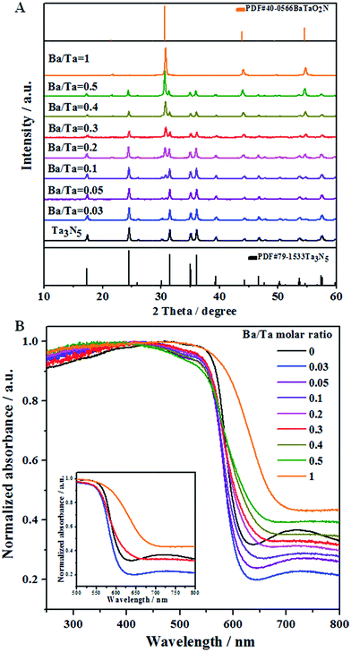
Fig. 1A shows XRD patterns of the Ba(n)–Ta3N5 samples (n = 0–1), in which all of them exhibit a well-crystallized feature. When the Ba/Ta molar ratio is below 0.03, only diffraction peaks assigned to a single phase of Ta3N5 are observed. With a further enhanced molar ratio of Ba/Ta, additional diffraction peaks attributed to BaTaO2N appear, the intensities of which are continuously increased. Compared with the diffraction peaks of the unmodified Ta3N5 sample, a little shift in the diffraction peaks toward a lower angle is observed for the barium-modified Ta3N5 samples (Fig. S1†). This demonstrates that the six-coordinated Ba2+ may be partly doped into Ta3N5 to substitute the Ta5+ sites, similar to the previous report.30Fig. 1B shows the UV-vis spectra of the Ba(n)–Ta3N5 samples, in which all of the samples similarly exhibit a wide visible light absorption at around 600 nm. The absorption edge is continuously red-shifted with the increasing molar ratio of Ba/Ta, which should be the result of the formed BaTaO2N species. Compared to the pristine Ta3N5 sample, the absorption background originating from the formation of reduced tantalum species (e.g., Ta4+ and Ta3+)43,44 on the Ba(n)–Ta3N5 samples undergoes an initial decrease and a subsequent increase with the enhancing molar ratio of Ba/Ta. To understand the UV-Vis results, a single phase of BaTaO2N was prepared via the same preparation procedure. As shown in Fig. 1B, the absorption edge of BaTaO2N is at about 660 nm, and its absorption background is the highest among all of the Ta3N5-based samples. It is generally understood that the UV-vis absorption background of the mechanically mixed sample containing two phases should be located between that of the corresponding single phases. That is to say, if the Ba(n)–Ta3N5 samples are just a simple mixture of Ta3N5 and BaTaO2N, the absorption background of the Ba(n)–Ta3N5 samples will lie between those of the Ta3N5 and BaTaO2N. In this work, however, the samples with a molar ratio of Ba/Ta below 0.3 exhibit much lower absorption backgrounds than those of both Ta3N5 and BaTaO2N. This means that the as obtained Ba(n)–Ta3N5 samples do not exist as a simple mixture of Ta3N5 and BaTaO2N, but exist as a nanocomposite. In consideration of that, here the Ta3N5 and BaTaO2N phases are one-pot synthesized, thus the BaTaO2N is expected to be formed in situ on the surface of Ta3N5 to partly eliminate the surface dangling bonds of Ta3N5. On the other hand, the partial barium ions are doped into Ta3N5 to inhibit the defect formation. Both of them cause the decrease of defect density. However, it needs to be pointed out that BaTaO2N itself exhibits the highest defect density among all of the samples. Thus, when the molar ratio of Ba/Ta is excessively enhanced, the defect density of the Ba(n)–Ta3N5 sample will become higher than that of Ta3N5. All of these factors should be integrally responsible for the initial decrease and subsequent increase of the absorption background (i.e. defect density) with the increasing molar ratio of Ba/Ta in the UV-Vis results (Fig. 1B).
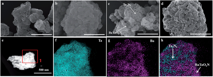
Fig. 2 shows FESEM images of typical samples. The Ta3N5 sample is porous (Fig. 2a), while the BaTaO2N sample has a shortage of porosity (Fig. 2b). The difference in their morphology can be easily judged from their mixed sample (Fig. 2c). However, the morphology feature of the chosen Ba(0.3)–Ta3N5 sample (Fig. 2d) prepared in this work is quite different from those of the corresponding single phases (Fig. 2a and b) or their mixed sample (Fig. 2c). As can be seen in Fig. 2d, the Ba(0.3)–Ta3N5 sample exhibits a homogeneous morphology with the two phases difficult to distinguish, demonstrating their interaction with each other as a nanocomposite. The formation of the Ta3N5/BaTaO2N nanocomposite can be further supported by the elemental mapping results (Fig. 2e–h). In Fig. 2f, the Ta element originating from both Ta3N5 and BaTaO2N is dispersed everywhere, while the Ba element that can only result from BaTaO2N is only found in some specific places (Fig. 2g). This can be easily understood to show that the places with Ba element mapping mainly reveal the existence of BaTaO2N, while the locations with Ta element mapping but a shortage of Ba element mapping stand for the Ta3N5 species. Based on the elemental mapping images, we can reasonably give a simulation of the composite state of Ta3N5 and BaTaO2N for the Ba(0.3)–Ta3N5 sample (Fig. 2h). For comparison, the element mapping results of mechanically mixed Ta3N5 and BaTaO2N (Ta3N5/BaTaO2N (0.3)-mix) are given in Fig. S2,† from which the Ta3N5 and BaTaO2N phases are mainly separated, different from that of the Ba(0.3)–Ta3N5 sample. It needs to be pointed out that the composite of Ta3N5 and BaTaO2N does not exist in a core–shell configuration. In addition, the surface areas of the Ba(n)–Ta3N5 samples are similar to that of BaTaO2N (7 m2 g−1) but a little lower than that of Ta3N5 (9 m2 g−1), which should result from their shortage of porous structure (Table 1).
| Entry | H2-evolving photocatalysts | Surface area (m2 g−1) | Half reactiona | Overall water splittingb | |
|---|---|---|---|---|---|
| H2 evolution rate (μmol h−1) | Gas evolution rates (μmol h−1) | ||||
| H2 | O2 | ||||
| a Reaction conditions: 0.15 g of 0.5 wt% Pt/Ba(n)–Ta3N5 (n = 0–1) and 0.5 wt% Pt/Ta3N5/BaTaO2N (0.3)-mix samples; 0.15 g of La2O3; aqueous methanol solution (150 mL, 20 vol%); 300 W xenon lamp (λ > 420 nm); 1 h irradiation. b Reaction conditions: 50 mg of 0.5 wt% Pt-modified H2-evolving photocatalysts; 50 mg of 0.45 wt% PtOx/WO3 as O2-evolving photocatalyst; 100 mL of aqueous NaI solution (1.0 mM); Pyrex top-irradiation type; 300 W xenon lamp (λ > 420 nm); 1 h irradiation. | |||||
| 1 | Ba(0)–Ta3N5 | 9 | 0.05 | 0 | 0 |
| 2 | Ba(0.03)–Ta3N5 | 7 | 0.1 | Trace | Trace |
| 3 | Ba(0.05)–Ta3N5 | 7 | 4.2 | 0.8 | 0.4 |
| 4 | Ba(0.1)–Ta3N5 | 7 | 6.6 | 2.0 | 1.0 |
| 5 | Ba(0.2)–Ta3N5 | 7 | 19.3 | 2.5 | 1.3 |
| 6 | Ba(0.3)–Ta3N5 | 7 | 30.2 | 3.2 | 1.6 |
| 7 | Ba(0.4)–Ta3N5 | 7 | 28.2 | 3.0 | 1.5 |
| 8 | Ba(0.5)–Ta3N5 | 7 | 24.6 | 2.1 | 1.1 |
| 9 | BaTaO2N | 7 | 9.5 | 0.3 | 0.15 |
| 10 | Ta3N5/BaTaO2N (0.3)-mix | 8 | 16.5 | 0.6 | 0.3 |
To further confirm the formation of the nanocomposite, we carried out a (HR)TEM characterization. Fig. 3 gives the representative images of the Ba(0.3)–Ta3N5 sample, in which the interface of the nanocomposite can be clearly observed. As shown in Fig. 3, the obvious lattice fringes indicate that the sample synthesized in this work is well-crystallized, in accordance with the XRD patterns (Fig. 1A). Based on the measurement of lattice distance, we can easily judge the BaTaO2N and Ta3N5 phases. Strikingly, the interfacial contact between BaTaO2N and Ta3N5 is very intimate, revealing the formation of the nanocomposite. The formation of the intimate interface should originate from the one-pot high temperature route and their similar Ta-based octahedron units. In this case, BaTaO2N is expected to be formed in situ on the surface of Ta3N5 during the one-pot nitridation process.
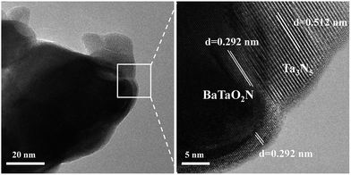 | ||
| Fig. 3 Representative TEM (left) and locally enlarged HRTEM (right) images of the chosen Ba(0.3)–Ta3N5 sample. | ||
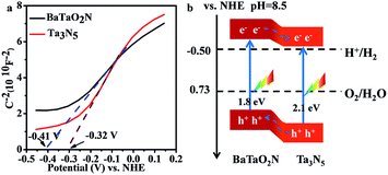
The relative band positions of Ta3N5 and BaTaO2N were analysed by combining their Mott–Schottky (M–S) plots and UV-Vis results. In Fig. 4a, the flat band potentials of BaTaO2N and Ta3N5 were evaluated according to M–S measurement results to be ca. −0.41 V and −0.32 V vs. NHE, respectively. In consideration of the fact that the bottom of the conduction band (CB) for one n-type semiconductor is normally more negative by ca. 0.2 V than the flat band potential,24,45,46 the CB positions of the n-type Ta3N5 and BaTaO2N are estimated to be −0.52 eV and −0.61 eV, respectively. By combining their bandgaps achieved from the UV-Vis results (Fig. 1B), the relative band positions of BaTaO2N and Ta3N5 are then deduced and given in Fig. 4b. Accordingly, the nanocomposite exists as a type II heterostructure, where the excited electrons are expected to transfer from the conduction band of BaTaO2N to that of Ta3N5, while the photogenerated holes will transfer in an opposite way, leading to the spatial charge separation.
The photocatalytic H2 evolution rates on the pristine and modified Ta3N5 samples were examined using the deposited platinum nanoparticle as the reduction cocatalyst in the presence of CH3OH under visible light irradiation (λ > 420 nm). No reaction takes place in the dark, and H2 is evolved only under light irradiation. As given in the half reaction part of Table 1, the rate of H2 evolution undergoes an initial increase and subsequent decrease with the increasing molar ratio of Ba/Ta, and the optimal value of the Ba/Ta molar ratio is 0.3. Compared to the Ta3N5 (entry 1), BaTaO2N (entry 9) or Ta3N5/BaTaO2N (0.3)-mix (entry 10) sample, the H2 evolution rate on the Pt/Ba(0.3)–Ta3N5 photocatalyst is remarkably promoted. The typical time curve of H2 evolution on the Pt/Ba(0.3)–Ta3N5 sample is given in Fig. S3,† in which it is almost linearly increased in the experimental region, demonstrating its good photochemical stability. In addition, only a small amount of N2 (less than 1 μmol) was detected in the initial stage of irradiation. The dependence of the H2 evolution rate on the Pt/Ba(0.3)–Ta3N5 photocatalyst as a function of irradiation wavelength is well consistent with that of the UV-vis spectra (Fig. S4†), indicating that the H2 evolution process is driven by the incident light.
Encouraged by the significantly enhanced H2 evolution rate, we tried to use the pristine or barium-modified Ta3N5 samples as H2-evolving photocatalysts to construct a Z-scheme overall water splitting system together with a PtOx/WO3 and IO3−/I− pair as an O2-evoloving photocatalyst and redox mediator, respectively. As shown in the overall water splitting part of Table 1, when using pristine Ta3N5 as the H2-evolving photocatalyst (entry 1), no obvious H2 evolution is detected, demonstrating the infeasibility of Ta3N5 itself to drive the Z-scheme overall water splitting process. However, using the barium-modified Ta3N5 samples as H2-evolving photocatalysts (entries 2–8), overall water splitting with H2/O2 molar ratios of close to 2![[thin space (1/6-em)]](https://www.rsc.org/images/entities/char_2009.gif) :
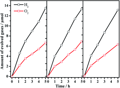
:![[thin space (1/6-em)]](https://www.rsc.org/images/entities/char_2009.gif) 1 is achieved, and the photocatalytic activity is dependent on the Ba/Ta molar ratio with an optimal value of ca. 0.3. The Z-scheme activities using the barium-modified samples as H2-evolving photocatalysts (entries 2–8) are all higher than those using BaTaO2N (entry 9) or the mixed sample (entry 10). The AQE was measured using the Ba(0.3)–Ta3N5 sample as the H2-evolving photocatalyst to be 0.1% at 420 nm. The activity trend is similar to the result of the photocatalytic proton reduction reaction, indicating that the overall water splitting performance is rate-determined by the H2-evolving side. In addition, the multiple cycles of time course curves further demonstrate its photochemical stability in the experimental region (Fig. 5). No obvious Ba2+ ion residue is observed in the centrifuged solution after reaction.
1 is achieved, and the photocatalytic activity is dependent on the Ba/Ta molar ratio with an optimal value of ca. 0.3. The Z-scheme activities using the barium-modified samples as H2-evolving photocatalysts (entries 2–8) are all higher than those using BaTaO2N (entry 9) or the mixed sample (entry 10). The AQE was measured using the Ba(0.3)–Ta3N5 sample as the H2-evolving photocatalyst to be 0.1% at 420 nm. The activity trend is similar to the result of the photocatalytic proton reduction reaction, indicating that the overall water splitting performance is rate-determined by the H2-evolving side. In addition, the multiple cycles of time course curves further demonstrate its photochemical stability in the experimental region (Fig. 5). No obvious Ba2+ ion residue is observed in the centrifuged solution after reaction.
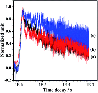
Photocatalytic overall water splitting commonly confronts huge challenges from both thermodynamic and kinetic aspects.2,47 In the past few decades, many candidate materials have satisfied the thermodynamics requirement, but overall water splitting on them is unfeasible because of the constraint of insufficient reaction kinetics in the H2 and/or O2-evolving side. Accordingly, developing strategies to address the water splitting reaction kinetics, which is greatly affected by the charge separation and surface catalytic process, is highly valuable. In this work, we adopt a simple one-pot nitridation approach with an ammonia flow (250 mL min−1) at high temperature (1223 K) to address the key issue of the charge separation via barium modification of Ta3N5. Based on our modification, not only is the defect density of Ta3N5 decreased, but also a Ta3N5/BaTaO2N heterostructure with intimate interfacial contact is formed for the promotion of spatial charge separation. Both of these are reasonably responsible for promoting photogenerated charge separation, contributing to the enhanced proton reduction performance as well as the feasible overall water splitting process. The promotion of charge separation is confirmed by comparing the time-resolved infrared spectra (TRIR) of the typical Ta3N5, BaTaO2N and Ba(0.3)–Ta3N5 samples (Fig. 6). The effective formation of the Ta3N5/BaTaO2N heterostructure probably originates from their similar structure units containing Ta-based octahedra. The decreased defect density of Ta3N5 originates from the part doping of Ba ions and the formation of BaTaO2N on the surface of Ta3N5 leading to surface passivation. It needs to be pointed out that with the increasing Ba/Ta molar ratio, the content of BaTaO2N with the highest defect density (see UV-Vis results in Fig. 1B) is enhanced, resulting in the increase of recombination centres, which is unfavourable for the photocatalytic H2 evolution process. As an integral factor of the heterostructure and the defect centres, the photocatalytic activity exhibits an initial increase and a subsequent decrease with the increasing molar ratio of Ba/Ta.
Conclusions
In summary, a simple one-pot nitridation strategy is adopted for the barium modification of Ta3N5 photocatalyst to address its poor photogenerated carrier separation ability as well as H2-evolving activity. The one-pot nitridation route overcomes well the challenge of low thermal stability in air for (oxy)nitride-related photocatalysts. Based on this, barium ions are partially doped into Ta3N5 to inhibit the formation of defects, and the residue amount of barium ions will cause the in situ formation of BaTaO2N on the surface of Ta3N5 to create an intimate interface for the Ta3N5/BaTaO2N heterostructure. Both of the structures favour the enhancement of charge separation efficiency as well as the promotion of the H2-evolving rate. Finally, we successfully achieve a Z-scheme overall water splitting process under visible light irradiation using the Ba-modified Ta3N5 as a H2-evolving photocatalyst. The fabrication of the heterostructure via a one-pot route is expected to be extended into more (oxy)nitride systems for promoted solar energy conversion.Acknowledgements
This work was financially supported by the Basic Research Program of China (973 Program: 2014CB239403) and National Natural Science Foundation of China (21373210, 21522306). F. Zhang thanks the “Hundred Talents Program” of Chinese Academy of Sciences for the preferential support.Notes and references
- K. Maeda and K. Domen, J. Phys. Chem. C, 2007, 111, 7851–7861 CAS.
- A. Kudo and Y. Miseki, Chem. Soc. Rev., 2009, 38, 253–278 RSC.
- R. Abe, J. Photochem. Photobiol., C, 2010, 11, 179–209 CrossRef CAS.
- X. Zong and L. Z. Wang, J. Photochem. Photobiol., C, 2014, 18, 32–49 CrossRef CAS.
- D. M. Fabian, S. Hu, N. Singh, F. A. Houle, T. Hisatomi, K. Domen, F. E. Osterloh and S. Ardo, Energy Environ. Sci., 2015, 8, 2825–2850 CAS.
- F. E. Osterloh, Chem. Mater., 2008, 20, 35–54 CrossRef CAS.
- H. Tong, S. X. Ouyang, Y. P. Bi, N. Umezawa, M. Oshikiri and J. H. Ye, Adv. Mater., 2012, 24, 229–251 CrossRef CAS PubMed.
- X. B. Chen, S. H. Shen, L. J. Guo and S. S. Mao, Chem. Rev., 2010, 110, 6503–6570 CrossRef CAS PubMed.
- Y. Wang, X. C. Wang and M. Antonietti, Angew. Chem., Int. Ed., 2012, 51, 68–89 CrossRef CAS PubMed.
- Y. Ma, X. L. Wang, Y. S. Jia, X. B. Chen, H. X. Han and C. Li, Chem. Rev., 2014, 114, 9987–10043 CrossRef CAS PubMed.
- K. Maeda, K. Teramura, D. L. Lu, T. Takata, N. Saito, Y. Inoue and K. Domen, Nature, 2006, 440, 295 CrossRef CAS PubMed.
- Y. Sasaki, H. Kato and A. Kudo, J. Am. Chem. Soc., 2013, 135, 5441–5449 CrossRef CAS PubMed.
- W. Y. Wang, J. Chen, C. Li and W. M. Tian, Nat. Commun., 2014, 5, 4647 CAS.
- C. S. Pan, T. Takata, M. Nakabayashi, T. Matsumoto, N. Shibata, Y. Ikuhara and K. Domen, Angew. Chem., Int. Ed., 2015, 54, 2955–2959 CrossRef CAS PubMed.
- Q. X. Jia, A. Iwase and A. Kudo, Chem. Sci., 2014, 5, 1513–1519 RSC.
- S. S. Chen, Y. Qi, T. Hisatomi, Q. Ding, T. Asai, Z. Li, S. S. K. Ma, F. X. Zhang, K. Domen and C. Li, Angew. Chem., Int. Ed., 2015, 54, 8498–8501 CrossRef CAS PubMed.
- D. J. Martin, P. J. T. Reardon, S. J. A. Moniz and J. W. Tang, J. Am. Chem. Soc., 2014, 136, 12568–12571 CrossRef CAS PubMed.
- G. G. Zhang, Z. A. Lan, L. H. Lin, S. Lin and X. C. Wang, Chem. Sci., 2016, 7, 3062–3066 RSC.
- G. Hitoki, A. Ishikawa, T. Takata, J. N. Kondo, M. Hara and K. Domen, Chem. Lett., 2002, 736–737 CrossRef CAS.
- A. Ishikawa, T. Takata, J. N. Kondo, M. Hara and K. Domen, J. Phys. Chem. B, 2004, 108, 11049–11053 CrossRef CAS.
- A. B. Murphy, P. R. F. Barnes, L. K. Randeniya, I. C. Plumb, I. E. Grey, M. D. Horne and J. A. Glasscock, Int. J. Hydrogen Energy, 2006, 31, 1999–2017 CrossRef CAS.
- S. S. K. Ma, T. Hisatomi, K. Maeda, Y. Moriya and K. Domen, J. Am. Chem. Soc., 2012, 134, 19993–19996 CrossRef CAS PubMed.
- Z. Wang, J. G. Hou, S. Q. Jiao, K. Huang and H. Zhu, J. Mater. Chem., 2012, 22, 21972–21978 RSC.
- S. S. Chen, G. J. Liu, Y. Qi, F. X. Zhang and C. Li, Angew. Chem., Int. Ed., 2015, 54, 3047–3051 CrossRef CAS PubMed.
- M. Tabata, K. Maeda, M. Higashi, D. L. Lu, T. Takata, R. Abe and K. Domen, Langmuir, 2010, 26, 9161–9165 CrossRef CAS PubMed.
- M. J. Liao, J. Y. Feng, W. J. Luo, Z. Q. Wang, J. Y. Zhang, Z. S. Li, T. Yu and Z. Z. Zou, Adv. Funct. Mater., 2012, 22, 3066–3074 CrossRef CAS.
- G. J. Liu, J. Y. Shi, F. X. Zhang, Z. Chen, J. F. Han, C. M. Ding, S. S. Chen, Z. L. Wang, H. X. Han and C. Li, Angew. Chem., Int. Ed., 2014, 53, 7295–7299 CrossRef CAS PubMed.
- L. Wang, N. T. Nguyen, X. M. Zhou, I. Hwang, M. S. Killian and P. Schmuki, ChemSusChem, 2015, 8, 2615–2620 CrossRef CAS PubMed.
- J. Seo, T. Takata, M. Nakabayashi, T. Hisatomi, N. Shibata, T. Minegishi and K. Domen, J. Am. Chem. Soc., 2015, 137, 12780–12783 CrossRef CAS PubMed.
- Y. B. Li, L. Zhang, A. Torres-Pardo, J. M. Gonzalez-Calbet, Y. H. Ma, P. Oleynikov, O. Terasaki, S. Asahina, M. Shima, D. Cha, L. Zhao, K. Takanabe, J. Kubota and K. Domen, Nat. Commun., 2013, 4, 2566 Search PubMed.
- G. J. Liu, S. Ye, P. L. Yan, F. Q. Xiong, P. Fu, Z. L. Wang, Z. Chen, J. Y. Shi and C. Li, Energy Environ. Sci., 2016, 9, 1327–1334 CAS.
- M. Y. Tsang, N. E. Pridmore, L. J. Gillie, Y. H. Chou, R. Brydson and R. E. Douthwaite, Adv. Mater., 2012, 24, 3406–3409 CrossRef CAS PubMed.
- L. Yuliati, J. H. Yang, X. C. Wang, K. Maeda, T. Takata, M. Antonietti and K. Domen, J. Mater. Chem., 2010, 20, 4295–4299 RSC.
- K. Maeda, N. Nishimura and K. Domen, Appl. Catal., A, 2009, 370, 88–92 CrossRef CAS.
- D. A. Wang, T. Hisatomi, T. Takata, C. S. Pan, M. Katayama, J. Kubota and K. Domen, Angew. Chem., Int. Ed., 2013, 52, 11252–11256 CrossRef CAS PubMed.
- X. M. Liu, L. Zhao, K. Domen and K. Takanabe, Mater. Res. Bull., 2014, 49, 58–65 CrossRef CAS.
- S. S. Chen, Y. Qi, Q. Ding, Z. Li, J. Y. Cui, F. X. Zhang and C. Li, J. Catal., 2016, 339, 77–83 CrossRef CAS.
- V. Strahle, Z. Anorg. Allg. Chem., 1973, 402, 47–57 CrossRef.
- J. Zhang, Q. Xu, Z. C. Feng, M. J. Li and C. Li, Angew. Chem., Int. Ed., 2008, 47, 1766–1769 CrossRef CAS PubMed.
- X. Wang, Q. Xu, M. R. Li, S. Shen, X. L. Wang, Y. C. Wang, Z. C. Feng, Y. S. Shi, H. X. Han and C. Li, Angew. Chem., Int. Ed., 2012, 51, 13089–13092 CrossRef CAS PubMed.
- J. Z. Su, L. J. Cuo, N. Z. Bao and C. A. Grimes, Nano Lett., 2011, 11, 1928–1933 CrossRef CAS PubMed.
- E. S. Kim, N. Nishimura, G. Magesh, J. Y. Kim, J. W. Jang, H. Jun, J. Kubota, K. Domen and J. S. Lee, J. Am. Chem. Soc., 2013, 135, 5375–5383 CrossRef CAS PubMed.
- J. Q. Wang, S. Y. Su, B. Liu, M. H. Cao and C. W. Hu, Chem. Commun., 2013, 49, 7830–7832 RSC.
- K. Maeda, M. Higashi, D. L. Lu, R. Abe and K. Domen, J. Am. Chem. Soc., 2010, 132, 5858–5868 CrossRef CAS PubMed.
- Y. Matsumoto, J. Solid State Chem., 1996, 126, 227–234 CrossRef CAS.
- S. S. Chen, Q. Yi, G. J. Liu, J. X. Yang, F. X. Zhang and C. Li, Chem. Commun., 2014, 50, 14415–14417 RSC.
- T. Hisatomi, J. Kubota and K. Domen, Chem. Soc. Rev., 2014, 43, 7520–7535 RSC.
Footnote |
| † Electronic supplementary information (ESI) available. See DOI: 10.1039/c6sc02750d |
| This journal is © The Royal Society of Chemistry 2017 |

