The quest for manganese-rich electrodes for lithium batteries: strategic design and electrochemical behavior
M. M.
Thackeray
*a,
J. R.
Croy
*a,
Eungje
Lee
a,
A.
Gutierrez
 a,
Meinan
He
a,
Joong Sun
Park†
a,
B. T.
Yonemoto‡
a,
B. R.
Long§
a,
J. D.
Blauwkamp¶
a,
C. S.
Johnson
a,
Youngho
Shin
b and
W. I. F.
David
cd
a,
Meinan
He
a,
Joong Sun
Park†
a,
B. T.
Yonemoto‡
a,
B. R.
Long§
a,
J. D.
Blauwkamp¶
a,
C. S.
Johnson
a,
Youngho
Shin
b and
W. I. F.
David
cd
aElectrochemical Energy Storage Department, Chemical Sciences and Engineering Division, Argonne National Laboratory, Lemont, Illinois 60439, USA. E-mail: thackeray@anl.gov
bMaterials Engineering Research Facility, Energy Sciences Division, Argonne National Laboratory, Lemont, Illinois 60439, USA
cISIS Neutron and Muon Source, Rutherford Appleton Laboratory, Harwell, OX11 0QX, UK
dInorganic Chemistry Laboratory, University of Oxford, South Parks Road, Oxford, OX1 3QR, UK
First published on 16th May 2018
Abstract
Manganese oxides, notably γ-MnO2 and modified derivatives, have played a major role in electrochemical energy storage for well over a century. They have been used as the positive electrode in primary (single discharge) Leclanché dry cells and alkaline cells, as well as in primary and secondary (rechargeable) lithium cells with non-aqueous electrolytes. Lithiated manganese oxides, such as LiMn2O4 (spinel) and layered lithium–nickel–manganese–cobalt (NMC) oxide systems, are playing an increasing role in the development of advanced rechargeable lithium-ion batteries. These manganese-rich electrodes have both cost and environmental advantages over their nickel counterpart, NiOOH, the dominant cathode material for rechargeable nickel–cadmium and nickel–metal hydride batteries, and their cobalt counterpart, LiCoO2, the dominant cathode material in lithium-ion batteries that power cell phones. An additional benefit is that tetravalent manganese can be used as a redox-active and/or stabilizing ‘spectator’ ion in lithiated mixed-metal oxide electrodes. This paper provides an overview of the historical development of manganese-based oxide electrode materials and structures, leading to advanced systems for lithium-ion battery technology; it updates a twenty-year old review of manganese oxides for lithium batteries. The narrative emanates largely from strategies used to design manganese oxide electrode structures at the Council for Scientific and Industrial Research, South Africa (1980–1994), Oxford University, UK (1981–1982), and Argonne National Laboratory, USA (1994–2017); it highlights the worldwide evolution of ideas and recent trends to improve the design, stability, and electrochemical capacity of structurally integrated, manganese-rich electrode materials.
Historical background
Manganese oxides are a structurally versatile family of compounds, existing in a wide variety of polymeric forms1 with atomic arrangements that provide an interstitial space of one-dimensional tunnels, two-dimensional layers, or three-dimensional intersecting channels. These compounds can act as a host framework for the intercalation and de-intercalation of guest ions, such as hydrogen or lithium ions. As such, they are of interest as insertion electrodes for aqueous and non-aqueous electrochemical cells and batteries.2,3In 1866, George Leclanché invented a 1.5 V Zn/MnO2 ‘wet’ cell, which contained a zinc anode, manganese dioxide cathode with a carbon current collector, and an ammonium chloride electrolyte solution.4 In 1886, Carl Gassner developed a ‘dry’ cell in which the ammonium chloride was contained in a ‘plaster of paris’ paste.4 The manganese dioxide that was commonly known at that time was nsutite, a naturally occurring manganese dioxide, simply referred to as γ-MnO2 (ref. 1) or ε-MnO2, depending on the quality of its X-ray diffraction (XRD) pattern.2 Nsutite electrodes were later replaced by higher quality synthetic γ-MnO2 products prepared by electrolytic or chemical methods. Electrolytic manganese dioxide, rather than chemically prepared manganese dioxide, is the preferred cathode material for alkaline Zn/MnO2 cells (also 1.5 V) introduced into the battery market in the late 1960s.5 An excellent historical account of the electrochemical reactions that occur during discharge of Zn/MnO2 cells is provided in a review by Chabre and Pannetier.2 By the 1960s, several groups had concluded that the monotonic drop in potential during discharge of the cells could be attributed to a H+-ion insertion reaction to form MnOOH (groutite),2,6–9 rather than a displacement or conversion reaction. Specifically, in 1966, Kozawa and Powers10 proposed that the reaction could be described as ‘a homogeneous single phase, solid state process, following previously introduced thermodynamic concepts of non-stoichiometric oxides’ by Vetter in 1962.2,11 This extensive characterization of γ-MnO2 as an insertion electrode was the forerunner to intense research into lithium intercalation compounds in the mid-to-late 1970s, such as graphite12–18 and the metal chalcogenides (e.g., TiS2 (ref. 19–21)). Subsequently, the metal oxides LiCoO2 (ref. 22 and 23) and LiMn2O4 (ref. 24–26) would spawn the non-aqueous carbon/lithium–metal-oxide battery industry in the early 1990s.
Attempts to develop and commercialize rechargeable alkaline Zn/MnO2 cells have not been hugely successful; the cells suffer from a poor cycle life because the reaction products cannot be fully recharged,27–29 and the zinc dendrites that form during charge can lead to internal short circuits.30,31 However, a recent report has indicated that Zn/MnO2 cells can be cycled with >80% energy efficiency for more than 3000 cycles if the depth of discharge is restricted to 10%.32
The structural complexity of γ-MnO2 materials is described in detail by Chabre et al.2 Simplistically, γ-MnO2 can be regarded as having a composite structure, depicted ideally in Fig. 1c, in which octahedral MnO6 units and (‘1 × 1’) dimensional channels of β-MnO2 (rutile-type structure, Fig. 1b) are intergrown with ramsdellite-MnO2 units and channels of larger (‘2 × 1’) dimension (Fig. 1a). Synthetic β-MnO2 tends to be anhydrous33 whereas the (2 × 1) channels in ramsdellite- and γ-MnO2 structures can be protonated or contain a minor amount of occluded water.1,2 In practice, the arrangement of the β-MnO2 and ramsdellite-MnO2 building blocks in γ-MnO2 is not ideal. The intergrown structures contain defects, stacking faults, and structural disorder that lead to XRD patterns with broad and sharp peaks, making accurate structural analysis of this family of compounds, and the differences between them, difficult.
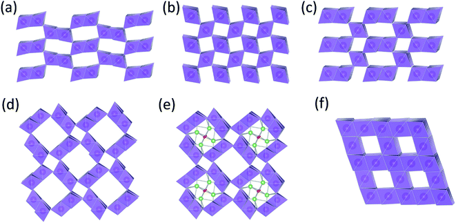 | ||
| Fig. 1 MnO2 structure types: (a) ramsdellite-MnO2, (b) β-MnO2 (rutile), (c) γ-MnO2, (d) α-MnO2 (hollandite), (e) Li2O-stabilized α-MnO2, and (f) λ-MnO2 (defect spinel). | ||
In 1975, Ikeda disclosed a 3 V non-aqueous primary Li/γ-MnO2 cell with a voltage double that of the aqueous Zn/MnO2 cell,34 which was commercialized the following year.35 In this case, the cathode was heat-treated at 350–430 °C to remove occluded and surface water from the electrode prior to cell assembly, thereby significantly improving the electrochemical properties and life of the cell.36 Lithium intercalation occurs predominantly in the ‘2 × 1’ channels of the heated γ-MnO2 structure. The ‘1 × 1’ channels of the rutile component are small and energetically resistant to lithium uptake, consistent with the finding that, when lithiated chemically at 50 °C, β-MnO2 transforms to spinel (LiMn2O4) to accommodate the additional lithium.37
Rechargeable lithium cells with pre-lithiated and heat-treated γ-MnO2 cathodes were subsequently developed for the battery market.38 The cathodes were prepared by reacting LiOH (or LiNO3) with γ-MnO2, typically in a 3![[thin space (1/6-em)]](https://www.rsc.org/images/entities/char_2009.gif) :
:![[thin space (1/6-em)]](https://www.rsc.org/images/entities/char_2009.gif) 7 molar ratio at 350–430 °C, to form an intergrown electrode structure, referred to as ‘composite dimensional manganese oxide’ (‘CDMO’) by Sanyo, which was initially believed to consist of structurally connected Li2MnO3 (Li
7 molar ratio at 350–430 °C, to form an intergrown electrode structure, referred to as ‘composite dimensional manganese oxide’ (‘CDMO’) by Sanyo, which was initially believed to consist of structurally connected Li2MnO3 (Li![[thin space (1/6-em)]](https://www.rsc.org/images/entities/char_2009.gif) :
:![[thin space (1/6-em)]](https://www.rsc.org/images/entities/char_2009.gif) Mn = 2
Mn = 2![[thin space (1/6-em)]](https://www.rsc.org/images/entities/char_2009.gif) :
:![[thin space (1/6-em)]](https://www.rsc.org/images/entities/char_2009.gif) 1) and lithium-stabilized γ-MnO2 components.39 This interpretation was later changed because a Li
1) and lithium-stabilized γ-MnO2 components.39 This interpretation was later changed because a Li![[thin space (1/6-em)]](https://www.rsc.org/images/entities/char_2009.gif) :
:![[thin space (1/6-em)]](https://www.rsc.org/images/entities/char_2009.gif) Mn ratio of 3
Mn ratio of 3![[thin space (1/6-em)]](https://www.rsc.org/images/entities/char_2009.gif) :
:![[thin space (1/6-em)]](https://www.rsc.org/images/entities/char_2009.gif) 7 (1
7 (1![[thin space (1/6-em)]](https://www.rsc.org/images/entities/char_2009.gif) :
:![[thin space (1/6-em)]](https://www.rsc.org/images/entities/char_2009.gif) 2.33) would thermodynamically favor the formation of a lithium–manganese-oxide spinel component at ∼400 °C, such as Li2Mn4O9 (Li
2.33) would thermodynamically favor the formation of a lithium–manganese-oxide spinel component at ∼400 °C, such as Li2Mn4O9 (Li![[thin space (1/6-em)]](https://www.rsc.org/images/entities/char_2009.gif) :
:![[thin space (1/6-em)]](https://www.rsc.org/images/entities/char_2009.gif) Mn = 1
Mn = 1![[thin space (1/6-em)]](https://www.rsc.org/images/entities/char_2009.gif) :
:![[thin space (1/6-em)]](https://www.rsc.org/images/entities/char_2009.gif) 2), rather than Li2MnO3, whose XRD patterns are similar.40,41
2), rather than Li2MnO3, whose XRD patterns are similar.40,41
These studies highlighted the concept of using composite electrode structures with electrochemically active and inactive components, the former contributing to capacity generation, and the latter providing structural stability. Subsequently, this approach was further exploited in designing advanced NMC electrode structures for lithium-ion batteries.
There also are MnO2 structures with tunnels of larger dimension, e.g., ‘2 × 2’ tunnels (hollandite), ‘2 × 3’ tunnels (romanechite), and ‘3 × 3’ tunnels (todorokite).1 The structure of hollandite, commonly known as α-MnO2 (Fig. 1d), is particularly intriguing; it has the characteristic ‘2 × 1’ MnO6 units of ramsdellite but also the characteristic (‘1 × 1’) channels of β-MnO2. The α-MnO2 framework contains stabilizing cations within the ‘2 × 2’ tunnels, for example, Na+, K+, Ca2+, or Ba2+ ions (Fig. 1e). The α-MnO2 structure can also be stabilized by hydronium (H3O+)42 or ammonium (NH4+)43 ions. In this case, negatively charged O2− and N3− ions are located at the center of the ‘2 × 2’ channels, occupying at least some of the vacant sites of a distorted close-packed oxygen array;44 the protons provide compensating positive charge within the ‘2 × 2’ channels necessary to stabilize the structure. A recent report has provided evidence that hydrated α-MnO2 is stabilized by both hydronium ions and water molecules.45 The α-MnO2 framework is zeolitic in nature; when this material is heated to 400 °C and cooled in a moist air, the water component can be reversibly removed from, and reincorporated, into the pores of the stable framework structure.46 The protons in H3O+-stabilized α-MnO2 can be ion-exchanged with lithium to yield products that provide superior capacity and electrochemical stability relative to metal-stabilized analogues (Na+, K+, Ca2+, Ba2+, etc.) in rechargeable 3 V Li cells.44,47 More recently, α-MnO2 has been identified as a promising electrocatalyst for Li-oxygen cells.46,48 This finding begs the question whether, in a hybrid Li-ion/Li–O2 system in which both manganese and oxygen participate in the electrochemical redox reactions, the electrocatalytic activity of α-MnO2 is associated with the removal of lithium and oxygen ions from the ‘2 × 2’ channels during charge, and re-accommodation during discharge.49
The advent of lithium-ion technology
The advent of lithium-ion batteries in 1991, with the introduction of high potential lithium–metal oxide cathodes, coupled to a carbon anode, was a game changer in the battery industry. It opened the door to the exploration, identification, and exploitation of a vast number of cathode compositions and structures.50–52 Remarkably, LiCoO2 (ref. 20) is still the cathode material of choice for the ever-expanding cell phone industry. The high cost of cobalt and the political instability of cobalt-producing countries have intensified worldwide efforts to use lithium-ion batteries with alternative cathode materials, such as nickel- and manganese-based metal oxides, for large-scale, heavy-duty batteries for hybrid and all-electric vehicles, as well as stationary energy storage for telecommunications, and back-up for the electrical grid. Partial substitution of cobalt by nickel and aluminum has provided alternative nickel-rich cathode compositions, e.g., LiNi0.8Co0.15Al0.05O2 (NCA),50,52 for high power applications such as electric vehicles. However, Ni-rich electrode materials such as NCA suffer from structural and chemical instabilities through oxygen loss above 4 V that can lead to a fast self-heating rate below 200 °C,53 thereby compromising the safety of lithium-ion cells.54 A concerted effort has therefore been made over the past two decades to replace or substitute cobalt and nickel in layered oxides with manganese, because lithium-ion cells with NMC cathodes offer competitive energy density and greater stability at high charging potentials (>4 V).54LiMn2O4 (spinel) and substituted derivatives
Fig. 2 presents a ‘compositional’ phase diagram for the Li–Mn–O system, constructed in the early 1990s to emphasize compositional and oxidation state differences that affect the electrochemical behavior of spinel-related electrodes.3,55 The diagram highlights, in particular, (i) the stoichiometric spinel tie-line between LiMn2O4 and Li4Mn5O12 represented by the Li1+xMn2−xO4 system (0 ≤ x ≤ 0.33), (ii) the stoichiometric lithiated spinel (rock-salt) tie-line between LiMn3O4 and Li7Mn5O12, and (iii) the LiMn2O4–Li4Mn5O12–MnO2 defect spinel tie-triangle, which contains, for example, λ-MnO2 and Li2Mn4O9.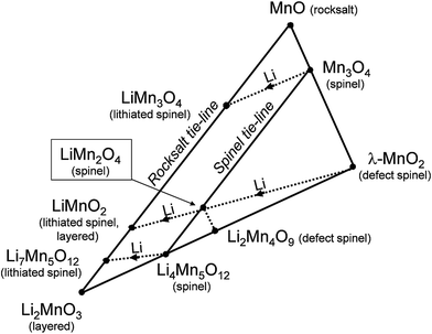 | ||
| Fig. 2 Compositional Li–Mn–O phase diagram with respect to spinel, rock salt, and layered compounds (adapted from Thackeray et al.55). | ||
Phase diagrams of lithium-ion electrode systems reported in the battery literature, e.g., Fig. 2, can reflect metastable materials formed by lithium insertion/extraction reactions at room temperature, each of which will have its own electrochemical signature. These diagrams, therefore, do not accurately indicate the stable compositions and structures that would co-exist under isothermal conditions, particularly at the high temperatures at which parent lithium metal oxide electrodes are synthesized. For example:
(1) In Fig. 2, the stoichiometric spinels LiMn2O4 and Li4Mn5O12 are typically prepared in air at 850 °C and 400 °C, respectively, while the metastable, defect-spinel λ-MnO2 (ref. 56) and the lithiated spinels Li2[Mn2]O4 and Li7[Mn5]O12 (ref. 25 and 55) can be prepared by chemical or electrochemical methods at room temperature. On heating in an inert atmosphere, the lithiated spinel Li2[Mn2]O4 will transform to orthorhombic LiMnO2 while, on heating in air, it will transform to Li2MnO3 and LiMn2O4. Note also that the composition LiMnO2 can have several structure types depending on the method and temperature of synthesis, for example, layered (monoclinic),57 lithiated spinel (tetragonal),25 and staggered (orthorhombic)58 configurations, or intergrowths between them.57
(2) In the Li–Co–O system, layered LiCoO2 is typically prepared at about 850 °C in air, whereas a metastable structural configuration approximating the lithiated spinel Li2[Co2]O4 (also LiCoO2) is generated at 400 °C; both structure types are preserved on cooling to room temperature but display significantly different electrochemical behavior.59–61
Fig. 2, coupled to supporting experimental data,25,55,62,63 underscores the following structure–electrochemical property relationships (at room temperature, ∼25 °C) in lithium–manganese-oxide spinel electrodes, notably those in the stoichiometric spinel Li1+xMn2−xO4 (0 ≤ x ≤ 0.33) system:
(1) Lithium insertion invokes an immediate first-order transition during discharge from a spinel to a rock-salt-type structure by displacing cations from tetrahedral to octahedral sites.25,55 This is an attractive electrochemical reaction because both spinel and rock-salt structures are found in nature and, therefore, represent intrinsically stable atomic configurations in the charged and discharged states of the electrode, respectively. In LiMn2O4 (x = 0), the spinel-to-rock-salt transition occurs by simultaneous lithium insertion and a two-phase conversion reaction, which results in a constant voltage discharge rather than a monotonically decreasing voltage expected for a homogeneous, single-phase (solid solution) reaction.
(2) The Li1+xMn2−xO4 (0 ≤ x ≤ 0.33) spinel structures on the LiMn2O4 (x = 0)–Li4Mn5O12 (x = 0.33) tie-line in Fig. 2 are cubic. Lithium insertion into these structures induces a Jahn–Teller (tetragonal) distortion when the average Mn oxidation state falls below 3.5+, i.e., when the Jahn–Teller active Mn3+ (d4) ion concentration reaches a critical value.55 The magnitude of the crystallographic distortion depends on the Mn3+-ion concentration. For example, electrochemical lithiation of cubic LiMn2O4 (average Mn oxidation state = 3.5+; c/a = 1) immediately yields tetragonal Li2Mn2O4 (average Mn oxidation state = 3.0+; c/a = 1.16).25,62 On the other hand, Li4Mn5O12 (average Mn oxidation state = 4.0+; c/a = 1) undergoes a cubic–cubic transition to yield Li6.5Mn5O12 (average Mn oxidation state = 3.5+; c/a = 1) before the tetragonal phase Li7Mn5O12 (average Mn oxidation state = 3.4+; c/a = 1.11) is formed;55 in this case, the Jahn–Teller effect is not as pronounced as it is in Li2Mn2O4. Note that this effect is also suppressed during the lithiation of the tetragonal spinel, Mn3O4 (c/a = 1.16); here, lithiation results in tetragonal LiMn3O4 (c/a = 1.05), which is close to cubic (c/a = 1.0), consistent with the reduction in the average Mn oxidation state from 2.67+ to 2.33+.25
(3) Lithium is extracted electrochemically from tetrahedral sites of the Li1+xMn2−xO4 spinel electrodes, such as LiMn2O4 (x = 0), at a potential of approximately 4 V vs. metallic lithium, whereas lithium is inserted into interstitial octahedral sites of the spinel structure at approximately 3 V to yield ordered rock-salt configurations.24,62–66 Cubic–cubic transitions are reversible, whereas cubic–tetragonal transitions tend to be less so, particularly when lithium insertion induces large anisotropic changes to the unit cell parameters.55
Despite the advantages of low cost and electrochemical stability (safety) that manganese offers over cobalt- and nickel-rich electrodes, LiMn2O4 and substituted derivatives (LMO), such as those containing excess lithium and a little aluminum to enhance structural and electrochemical stability,67–69 provide inferior capacity and energy output relative to LiCoO2 (LCO) and LiNi0.8Co0.15Al0.05O2 (NCA) electrodes. However, manganese dissolution from LMO electrodes, which has been attributed to the disproportionation reaction Mn3+ → Mn4+ and Mn2+ at the particle surface,56,70,71 severely compromises the cycle life of carbon/LiMn2O4 lithium-ion cells.71 Nevertheless, significant progress has been made in enhancing surface stability, reducing manganese dissolution, and alleviating capacity fade through a wide variety of surface treatments.72–77 Although LMO does not compete directly with LCO, NCA, and NMC cathodes in terms of capacity, energy output, and cycling stability, LMO has been blended with these cathode materials to offset the higher cost of cobalt and nickel.78 The high-potential (4.7 V) LixMn1.5Ni0.5O4 spinel (0 ≤ x ≤ 2) is receiving particular attention for next generation systems because it offers the possibility of significantly increasing the energy and power of a lithium-ion cell relative to an all-manganese (4.1 V) LMO cathode. Note that (1) in a standard LixMn2O4 electrode, the manganese ions are redox active over the full range of x (0 ≤ x ≤ 2), whereas, ideally, in well-ordered LixMn1.5Ni0.5O4 electrodes, the Mn4+ ions are electrochemically inactive and play a spectator role that allows reversible Ni2+ to Ni4+ redox reactions to occur over the range 0 ≤ x ≤ 1; and (2), for the range 1 < x ≤ 2, the damaging Jahn–Teller (Mn3+) effect in LixMn1.5Ni0.5O4 electrodes during lithium insertion at 3 V is not as pronounced as it is in LixMn2O4 electrodes, the average manganese oxidation state at the end of discharge of these two electrodes at x = 2 being 3.3+ and 3.0+, respectively.25,79,80 However, to date, electrolyte instability at 4.7 V has precluded the commercialization of LiMn1.5Ni0.5O4 spinel electrodes in Li-ion cells.
Li2O-stabilized MnO2 structures
Early studies of lithium–manganese-oxide spinel systems exposed the importance of lithia (Li2O) as a stabilizing component in manganese oxide structures, in which the oxygen ions of the lithia and manganese oxide components form a close-packed oxygen array.3 For example:(1) Li2O-stabilized α-MnO2 with 1-D channels provides significantly superior electrochemical properties relative to metal cation-substituted α-MnO2 derivatives, such as K+-stabilized α-MnO2.40,44
(2) Li2MnO3 (Li2O·MnO2) has a Li2O-stabilized, layered (2-D) MnO2 rock-salt configuration, which is electrochemically inactive as an insertion electrode below ∼4.5 V vs. metallic lithium.3,81
(3) The spinel Li4Mn5O12, alternatively 2Li2O·5MnO2, with 3-D channels for Li+-ion transport, provides superior cycling stability to lithium insertion/extraction at 3 V relative to LiMn2O4 by mitigating the Jahn–Teller effect.55
Lithia also stabilizes other transition metal oxide electrode materials. For example, V2O5 reacts with lithia to form LiV3O8 (Li2O·V2O5),82,83 which markedly improves the structural stability and electrochemical properties (e.g., energy and power) of the electrode system relative to unlithiated V2O5, notably in solid state lithium-polymer electrolyte cells that operate close to 100 °C.84,85 The realization that lithia could be used effectively as a stabilizing component in metal oxides subsequently led to the design of structurally integrated electrodes and lithium-ion systems with enhanced electrochemical properties, particularly those with a Li2MnO3 (Li2O·MnO2) component.86,87
Layered lithium manganese oxides and substituted derivatives
Layered manganese oxide structures, such as the minerals birnessite [Na,Ca,Mn(2+)]Mn7O14·2.8H2O, lithiophorite LiAl2[Mn(4+)2Mn(3+)]O6(OH)6, and chalcophanite ZnMn(4+)3O7·3H2O, occur in nature.1 As the formulae indicate, their structures are stabilized by metal cations, water molecules, and/or hydroxide ions. Prior to the introduction of Li-ion batteries into the market in 1991, no anhydrous layered LiMnO2 analogue of LiCoO2 and LiNiO2 was known.Li2MnO3
In the late 1980s and early 1990s, Rossouw et al. synthesized a layered MnO2 structure by digesting and leaching lithium from Li2MnO3 (Fig. 3a), which can be represented, alternatively, in layered notation as Li[Li0.33Mn0.67]O2.3,88,89 Acid treatment of Li2MnO3 is accompanied first by the exchange of Li+ by H+ in the lithium layer to yield H1.5Li0.5MnO3 (alternatively, H[Li0.33Mn0.67]O2); during this process, the close-packed oxygen planes (i.e., O3 stacking) shear to trigonal prismatic (P3) stacking.89–91 Further acid treatment removes both lithium and oxygen from the structure to yield a layered product (H,Li)2−xMnO3−x/2 that contains both protons and residual Li+ ions.89 Attempts to create an anhydrous, layered structure by heating (H,Li)2−xMnO3−x/2 have been unsuccessful. The structure transforms to γ-MnO2 under prolonged acid treatment;92 the transformation also occurs when highly delithiated (H,Li)2−xMnO3−x/2 products are stored in air.93 | ||
| Fig. 3 Idealized close-packed structures of (a) layered Li2MnO3, (b) layered LiMO2 (M = Co, Ni, Mn), and (c) cubic spinel LiMn2O4. | ||
Chemical re-lithiation of (H,Li)2−xMnO3−x/2 with LiI in acetonitrile results in the exchange of protons by lithium ions with concomitant reduction of the manganese ions to yield the composition Li1.1Mn0.9O2;89 discounting any remaining protons, this formula can be written, alternatively, as 0.2Li2MnO3·0.8LiMnO2.86 Re-lithiation of (H,Li)2−xMnO3−x/2 with LiI regenerates the close-packed oxygen array of the parent Li2MnO3 structure.
The electrochemical extraction of lithium from Li2MnO3 at 4.5 V and above was first reported by Kalyani et al.94 and subsequently by the Bruce group.81,95 The activation of a supposedly ‘inactive’ electrode material was attributed to the loss of oxygen that accompanied lithium extraction at high potentials with a compositional net loss of ‘Li2O’ (i.e., Li2−xMnO3−x/2), possibly facilitated by proton exchange. The loss of Li2O from Li2MnO3 (Li2O·MnO2) increases the concentration of the MnO2 component within the structure, thereby rendering the electrode electrochemically active to lithium insertion and extraction. Electrochemically activated Li2MnO3 electrodes do not cycle well, presumably because, like acid-treated Li2MnO3 electrodes, the layered structure transforms readily to a spinel-type configuration.81 The exploitation of oxygen redox reactions in high-capacity Li2MnO3-stabilized electrodes is discussed later in this paper.
The preparation of anhydrous layered LiMnO2 from the isostructural sodium analogue, NaMnO2, by ion exchange with Li in a non-aqueous solvent was reported in 1996 almost simultaneously by Delmas et al.96 and Bruce et al.57 Layered LiMnO2 and substituted derivatives, such as LiMn2−xCoxO2 (0 < x ≤ 0.5), are electrochemically unstable;97 on cycling, manganese is displaced from the Mn-rich layers to adjacent lithium-depleted layers, thereby transforming to a structure with spinel-like character, consistent with the electrochemical behavior of Li2MnO3.81 The layered-to-spinel phase transition occurs via the disproportionation reaction:
| 2Mn3+ → Mn4+ + Mn2+ |
Trivalent Mn3+ ions in the octahedral sites of the manganese layer are displaced via tetrahedral sites, where they reside temporarily as Mn2+ (d5) ions, into octahedral sites of the lithium-depleted layer before being simultaneously re-oxidized to generate localized spinel-like arrangements within a residual layered matrix.97,98 The displacement of the manganese ions, induced by the lithium extraction process at moderately high potentials, is disadvantageous because the uncontrolled formation of a structure with intermediate layered–spinel character leads to a pronounced hysteresis in the charge/discharge profile.97
Layered LiMO2 (M = Co, Ni, Mn)
The introduction of LiCoO2 as a viable lithium-ion cathode material resulted in concerted efforts during the 1990s to synthesize layered mixed-metal oxide electrode structures,50 such as lithium–cobalt–nickel oxides,99,100 lithium–manganese–nickel oxides,101,102 lithium–manganese–cobalt oxides,103,104 and lithium–manganese–chromium oxides.105,106 These studies were later expanded to include ternary and higher-order transition metal oxide systems, notably NMC electrodes.Advances in designing layered electrode structures
At present, NMC materials, LiCoO2, LiNi0.80Co0.15Al0.05O2, substituted derivatives of LiMn2O4, and olivine LiFePO4 (LFP),107–109 which was discovered in 1996, constitute the dominant cathode materials in the lithium-ion battery industry. Substituted Li1+xMn2−x−yMyO4 (e.g., M = Al) spinel and LFP electrode structures and compositions have been optimized by industry and do not compete with layered metal oxide cathodes from a cell capacity and energy standpoint. The best opportunity for advancing lithium-ion battery cathodes, therefore, rests with layered metal oxides and, in particular, NMC materials. Nickel-rich NMC electrode materials are currently in vogue because they offer high energy and power, but are compromised by thermal instability and safety concerns at high states of charge, while layered Mn-rich NMC electrodes suffer from structural instability and low power, yet remain attractive because of their potential energy, cost, and safety advantages.Li2MnO3-stabilized electrode structures
Lithium extraction from layered LiMO2 electrode structures, in general, reduces the binding energy between the oxygen layers, thereby destabilizing lithium-deficient materials. Therefore, it is not surprising that phase transitions can be induced by displacing transition metal ions from their layer to sites left vacant by the exiting lithium ions in adjacent layers, or by sliding the close-packed oxygen planes to reduce the free energy of the electrode system.81,110,111 For Li1−xCoO2, these damaging transitions start to occur when x ≈ 0.5,112 which corresponds to a capacity of approximately 140 mA h g−1, whereas the transformation from layered LiMnO2 to spinel LiMn2O4 occurs almost immediately with lithium extraction.81 More lithium (i.e., x > 0.5) can be extracted from Ni-substituted layered electrodes, such as Li1−xNi0.80Co0.15Al0.05O2 and Li1−xNi0.0.33Mn0.33Co0.33O2, in which Al and Mn play a stabilizing role, before major structural changes occur, thereby increasing the capacity and energy of the cell.52 One concept to suppress phase transitions in layered LiMO2 cathodes, and thereby enhance cell capacity and energy, is to integrate a structurally compatible, and electrochemically inactive, layered Li2M′O3 (M′ = Mn, Ti, Zr) component (Li2O·M′O2) with the electrochemically active LiMO2 component.86,87,113–116 These materials are commonly formulated as xLi2M′O3·(1 − x)LiMO2 to emphasize their structural components and composition. At present, systems in which M′ = Mn and M = Ni, Mn, and Co are receiving the most attention. They are also referred to as ‘layered–layered’ electrodes, because it is easy to follow the compositional changes during electrochemical lithium extraction/reinsertion reactions on a xLi2M′O3–LiMO2–M′′O2 phase diagram (M′′ = MM′).86 This design concept mimics the intergrowth structure of γ-MnO2, as discussed earlier, in which the ramsdellite-MnO2 component is electrochemically active to lithium insertion/extraction, while the β-MnO2 component provides structural stability and is essentially inactive to lithium uptake. For this reason, the term ‘composite structure’ has been used to describe ‘layered–layered’ Li2MnO3-stabilized LiMO2 electrode materials.87 Note that the ‘layered–layered’ formula xLi2MnO3·(1 − x)LiMO2 can be normalized to the standard layered (rock-salt) notation Li1+(x/2+x)M′1+(x/(2+x))O2 in which M′ = Mn + M or, more simply, Li1+yM′1−yO2 where y = (x/(2 + x)). Although the structures of these layered materials have also been referred to as ‘solid solutions,’ in reality they are inhomogeneous and highly complex.117Structurally integrated cathode materials are being explored worldwide, particularly those using Li2MnO3 as a stabilizing component, integrated either with another structurally compatible layered component, LiMO2 (M = Mn, Ni, Co), or a LiM′2O4 spinel component, or both. Numerous reports of the structural and electrochemical properties of these materials, both experimental and theoretical, have appeared in the literature over the past decade, many of which are cited in the references listed herein. Specifically, readers are referred to recent reviews of these materials by Croy et al.,118 Passerini et al.,119 Zheng et al.,120 and Manthiram et al.121 and to computational studies by Benedek and Iddir,122–124 Persson et al.,125,126 and Wolverton et al.127 These articles provide guidance in understanding the complex structural and electrochemical features of Li2MnO3-based systems.
Structural considerations
Fig. 3 illustrates the idealized and well-known structures of (a) layered Li2MnO3, (b) layered LiMO2 (M = Co, Ni, and Mn), and (c) spinel LiMn2O4, i.e., the components under consideration for designing structurally integrated ‘layered–layered’, ‘layered–spinel’, and ‘layered–layered–spinel’ electrode materials. The LiMn2O4 spinel structure has an ideal cubic-close-packed (ccp) oxygen array, whereas the layered rock-salt structures Li2MnO3 (monoclinic) and LiMO2 (M = Co,Ni – monoclinic, M = Mn – trigonal) deviate slightly from ideal ccp stacking. In an ideal LiMO2 layered structure (Fig. 3b), trivalent M and monovalent Li ions occupy the octahedral sites in alternate layers in a 1![[thin space (1/6-em)]](https://www.rsc.org/images/entities/char_2009.gif) :
:![[thin space (1/6-em)]](https://www.rsc.org/images/entities/char_2009.gif) 1 ratio. In Li2MnO3, or in layered LiMO2 notation, Li[Li1/3Mn2/3]O2 (Fig. 3a), lithium ions fully occupy the octahedral sites of one layer and share the octahedral sites in every alternate layer with tetravalent manganese ions in a 1
1 ratio. In Li2MnO3, or in layered LiMO2 notation, Li[Li1/3Mn2/3]O2 (Fig. 3a), lithium ions fully occupy the octahedral sites of one layer and share the octahedral sites in every alternate layer with tetravalent manganese ions in a 1![[thin space (1/6-em)]](https://www.rsc.org/images/entities/char_2009.gif) :
:![[thin space (1/6-em)]](https://www.rsc.org/images/entities/char_2009.gif) 2 ratio. In LiMn2O4 (Fig. 3c), tetravalent and trivalent Mn ions (net oxidation state = 3.5+) occupy one-half of the octahedral sites; they are distributed in an ordered configuration in alternate layers in a 3
2 ratio. In LiMn2O4 (Fig. 3c), tetravalent and trivalent Mn ions (net oxidation state = 3.5+) occupy one-half of the octahedral sites; they are distributed in an ordered configuration in alternate layers in a 3![[thin space (1/6-em)]](https://www.rsc.org/images/entities/char_2009.gif) :
:![[thin space (1/6-em)]](https://www.rsc.org/images/entities/char_2009.gif) 1 ratio, thus imparting some layered character to the spinel structure.
1 ratio, thus imparting some layered character to the spinel structure.
Fig. 4a shows the building block of Li2MnO3, which has been proposed to play a key role in stabilizing layered86,87,116 and spinel128–130 electrode structures. The lithium and manganese ions are each bonded to six oxygen ions in octahedral coordination and are ordered such that each lithium ion in the manganese layer has six nearest neighbor manganese ions, as depicted by the LiMn6 configurations in Fig. 4b. Fig. 4c is an idealized representation of the cation distribution in the transition metal layers of a 0.5Li2MnO3·0.5LiMn0.5Ni0.5O2 electrode structure.131 These layers consist of an interconnected array of LiMn6 and NiMn6 units, which represent the Li2MnO3 and LiMn0.5Ni0.5O2 components of the structure, respectively (Fig. 4c). Note that in 0.5Li2MnO3·0.5LiMn0.5Ni0.5O2, the manganese ions are all tetravalent while the nickel ions are divalent, as they are in layered LiMn0.5Ni0.5O2 alone132 and in the spinel LiMn1.5Ni0.5O4.133 Below ∼4.5 V, all the electrochemical capacity of the electrode is derived from Ni2+ ↔ Ni4+ redox reactions, while the tetravalent manganese ions act as ‘spectator’ ions and stabilizing agents. By contrast, in 0.5Li2MnO3·0.5LiCoO2, the Li2MnO3 and LiCoO2 components tend to phase segregate during synthesis,134 forming interconnected nanodomains in a complex mosaic pattern.135
‘Layered–layered’ electrodes: the Li2MnO3–LiMO2–MO2 system
A compositional phase diagram of the Li2MnO3–LiMO2–MO2 (M = Mn, Ni, Co) system is shown in Fig. 5. The Li2MnO3–LiMO2 tie-line represents the compositions of structurally integrated ‘layered–layered’ xLi2MnO3·(1 − x)LiMO2 electrode materials described in the preceding section. Lithium extraction from these materials occurs first with a concomitant oxidation of the transition metal (M) cations in the LiMO2 component. During this reaction, the composition of the electrode follows the direction of the arrows away from the xLi2MnO3·(1 − x)LiMO2 tie-line. For a standard LiCoO2 electrode (i.e., x = 0, M = Co), lithium extraction follows the black arrow along the LiMO2–MO2 tie-line, which represents a continually changing electrode composition, e.g., Li1−xCoO2, as x increases. When charged to 4.3 V, approximately one-half of the lithium ions can be extracted reversibly from LiCoO2, which corresponds to a capacity of ∼140 mA h g−1, before the onset of structural perturbations and reactions with the electrolyte.111,112 Slightly higher reversible capacities can be achieved from NMC electrodes when a small amount of additional lithium is added to the electrode composition.136 These lithium-rich and manganese-containing electrodes can be represented by the notation xLi2MnO3·(1 − x)LiMO2, because the excess lithium together with some manganese can constitute the Li2MnO3 component of the electrode structure.87 Lithium extraction from slightly lithium-rich NMC electrodes follows the red reaction path on the Li2MnO3–LiMO2–MO2 phase diagram in Fig. 5; these electrodes yield a slightly higher capacity than LiCoO2, typically ∼160 mA h g−1 when charged to 4.3 V.136 In this instance, the Li2MnO3 component is electrochemically inactive and acts as a spectator ion and stabilizing agent, allowing extra capacity (i.e., lithium) to be cycled during charge and discharge relative to stoichiometric (LiMO2) NMC electrodes. Lithium-rich NMC electrodes demonstrate an enhanced rate capability, which is dependent on the relative amounts of nickel, manganese, and cobalt.137,138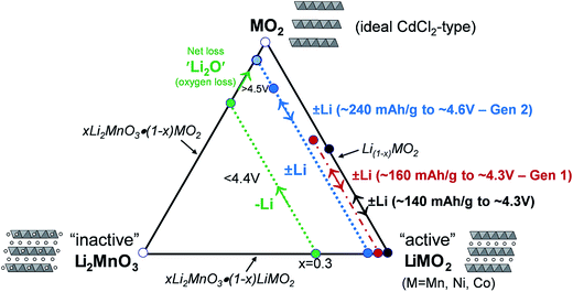 | ||
| Fig. 5 Li2MnO3–LiMO2–MO2 compositional phase diagram (adapted from Thackeray et al.86,87). | ||
The amount of inactive Li2MnO3 in the xLi2MnO3·(1 − x)LiMO2 electrode increases with x. Therefore, when charged to 4.3 V, electrodes with higher values of x provide a lower capacity as indicated by the short reaction path for x = 0.3, highlighted in green, for complete lithium extraction from the LiMO2 component, relative to the LiMO2-to-MO2 reaction (i.e., x = 0), highlighted in black. However, for electrodes with x = 0.3, if charged above 4.5 V, lithium can be extracted from the Li2MnO3 component with a concomitant loss of oxygen (net loss Li2O), which drives the composition of the electrode towards the MO2 apex of the phase diagram, thereby increasing the concentration of an electrochemically active MnO2 component in the structure, and hence the capacity of the electrode.87,139–141 The reaction is complex, particularly during the early break-in cycles above 4.5 V. Not much gaseous oxygen is observed during lithium extraction at such high potentials,142 which implies that some undetected oxygen may react immediately with, and oxidize, the electrolyte at the particle surface.121 In studies of lithium-rich metal oxide electrodes at high potentials, hybridization of the transition metal d and oxygen 2p bands has been given as a reason for the oxygen redox activity.121,143,144 Recently, Ceder et al. proposed that the oxygen redox capacity is also dependent on the need for particular Li–O–Li configurations within these structures.145 The anomalously high capacity (∼300 mA h g−1) that can be obtained from fully activated electrodes is significantly higher than the expected theoretical value for transition metal redox reactions alone (∼260 mA h g−1).114 These high capacity reactions involving oxygen are partially reversible;146,147 however, the capacity diminishes on extended cycling, consistent with progressive oxygen loss, to values that can be attributed solely to redox reactions on the transition metal ions.
Lithium- and manganese-rich ‘layered–layered’ electrode structures have high capacity but are unstable when cycled repeatedly to high potentials (>4.5 V).114,119–121,148,149 This inherent instability is not surprising, given that layered LiMnO2 electrodes convert to spinel-like configurations, a process that involves the migration of manganese from the transition-metal layers to the lithium-depleted layers with the evolution of the characteristic 4 V and 3 V electrochemical signatures of a LiMn2O4 spinel electrode. Lithium- and manganese-rich xLi2MnO3·(1 − x)LiMO2 electrodes, such as 0.5Li2MnO3·0.5LiMn0.375Ni0.375Co0.250O2, exhibit a similar ‘voltage fade’ towards 3 V on cycling (Fig. 6) – a result of interlayer metal migration that generates a structure with a lower Gibbs free energy relative to the parent layered material. When activated at high potentials, the electrochemical properties of these complex mixed-metal oxides are also highly dependent on the electrode composition, i.e., the Ni![[thin space (1/6-em)]](https://www.rsc.org/images/entities/char_2009.gif) :
:![[thin space (1/6-em)]](https://www.rsc.org/images/entities/char_2009.gif) Mn
Mn![[thin space (1/6-em)]](https://www.rsc.org/images/entities/char_2009.gif) :
:![[thin space (1/6-em)]](https://www.rsc.org/images/entities/char_2009.gif) Co ratio. For example, Long et al.130 at Argonne National Laboratory have shown that the electrochemical properties of 0.25Li2MnO3·0.75LiMnyNiyCo1−2yO2 electrodes are strongly dependent on the value of y. The cycling protocol typically adopted at Argonne to evaluate ‘layered–layered’ compositions and structures is to subject lithium cells initially to one formation cycle between 4.6 and 2.0 V and, thereafter, to continuous cycling between ∼4.45 and ∼2.50 V.130 Capacity vs. cycle number plots and corresponding dQ/dV plots of a Li/0.25Li2MnO3·0.75LiMnyNiyCo1−2yO2 cell are provided in Fig. 7a–c and d–f, respectively. The data clearly show enhanced cycling capacity and stability, as well as the suppression of voltage fade, when the electrode has a relatively high manganese and nickel content (y) and a low cobalt content (1 − 2y).
Co ratio. For example, Long et al.130 at Argonne National Laboratory have shown that the electrochemical properties of 0.25Li2MnO3·0.75LiMnyNiyCo1−2yO2 electrodes are strongly dependent on the value of y. The cycling protocol typically adopted at Argonne to evaluate ‘layered–layered’ compositions and structures is to subject lithium cells initially to one formation cycle between 4.6 and 2.0 V and, thereafter, to continuous cycling between ∼4.45 and ∼2.50 V.130 Capacity vs. cycle number plots and corresponding dQ/dV plots of a Li/0.25Li2MnO3·0.75LiMnyNiyCo1−2yO2 cell are provided in Fig. 7a–c and d–f, respectively. The data clearly show enhanced cycling capacity and stability, as well as the suppression of voltage fade, when the electrode has a relatively high manganese and nickel content (y) and a low cobalt content (1 − 2y).
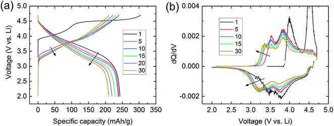 | ||
| Fig. 6 (a) Voltage fade profiles and (b) corresponding dQ/dV plots during cycling of a Li/0.5Li2MnO3·0.5LiMn0.375Ni0.375Co0.250O2 cell. | ||
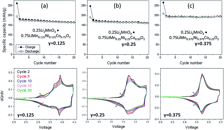 | ||
| Fig. 7 Electrochemical cycling stability (top) and dQ/dV plots (bottom) of ‘layered–layered’ 0.25 Li2MnO3·0.75LiMnyNiyCo1−2yO2 electrodes in lithium cells: (a) y = 0.125, (b) y = 0.250, and (c) y = 0.375 (reproduced with permission from J. Electrochem. Soc., Long et al.130 Copyright 2014, The Electrochemical Society). | ||
Although synthesizing high-quality xLi2MnO3·(1 − x)LiMO2 electrode materials reproducibly can be difficult, Fig. 8 highlights the electrochemical stability of a Li/0.5Li2MnO3·0.5LiMn0.5Ni0.5O2 cell after activating the cathode at 4.6 V for several cycles to induce voltage fade.150 In this instance, voltage vs. capacity plots of cycles 15 to 25 (i.e., after electrochemical activation) and corresponding dQ/dV plots of this cell (Fig. 8a and b, respectively), cycled continuously between 4.6 and 2.0 V, show that the charge and discharge reactions are remarkably reversible during these early cycles. However, (1) the Ni reduction peak at 3.7 V is significantly weaker than it is for the relatively stable 0.25Li2MnO3·0.75LiMnyNiyCo1−2yO2 electrode in Fig. 7c, which was charged to a slightly lower voltage limit (4.45 V), and (2) most of the discharge occurs below 3.5 V. This voltage fade, which causes asymmetry in the charge and discharge profiles because of transition metal migration during lithium insertion/extraction reactions, is disadvantageous for several reasons:151–153
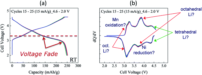 | ||
Fig. 8 Cycling stability of Li/0.5Li2MnO3·0.5LiMn0.5Ni0.5O2 cell (Mn![[thin space (1/6-em)]](https://www.rsc.org/images/entities/char_2009.gif) : :![[thin space (1/6-em)]](https://www.rsc.org/images/entities/char_2009.gif) Ni ratio = 3 Ni ratio = 3![[thin space (1/6-em)]](https://www.rsc.org/images/entities/char_2009.gif) : :![[thin space (1/6-em)]](https://www.rsc.org/images/entities/char_2009.gif) 1): (a) voltage vs. capacity plots (cycles 15, 20, and 25) and (b) corresponding dQ/dV plot. 1): (a) voltage vs. capacity plots (cycles 15, 20, and 25) and (b) corresponding dQ/dV plot. | ||
(1) it causes hysteresis in the charge/discharge process;
(2) it reduces the energy output of the cell;
(3) it increases cell impedance at both high and low states of charge, thereby lowering lithium diffusion rates (power); and
(4) it compromises the management of cells and batteries.
Despite these negative attributes, high-capacity ‘layered–layered’ xLi2MnO3·(1 − x)LiMO2 electrodes continue to receive worldwide attention in attempts to find ways to mitigate their limitations, particularly the suppression or elimination of transition-metal migration during electrochemical reactions when the electrodes are charged to 4.5 V and above.
Configurational considerations
The complex interconnected nanodomains observed in 0.5Li2MnO3·0.5LiCoO2 can be addressed in simple terms by using Pauling's principle of electrostatic valence. Consider the oxygen coordination in LiCoO2 and Li2MnO3. In LiCoO2, each oxygen is surrounded by three Li+ and three Co3+ ions. Given that all cations are octahedrally coordinated by six oxygen ions, and each oxygen ion is correspondingly coordinated by six cations, and following Pauling's principle, the Li+–O2− and Co3+–O2− bonds will have formal valences of and
and  , respectively. For each oxygen, the lithium layer contributes
  summed bond valence while the Co layer contributes
  . This leads to a total formal bond valence of +2, which charge balances the formal valence of O2−. The situation with Li2MnO3 is similar except that the total LiMn2 metal layer bond valence of
  is the sum of
  . This can be expressed in the rule that the sum of the formal valence of the cation triangles in the metal layer should equal 9 for charge balancing between nearest neighbor cations and anions.
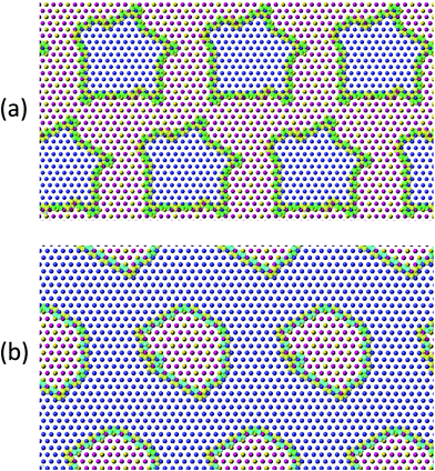
To investigate cation ordering in the metal layer, a simulated annealing cation-swapping optimization algorithm, which minimizes the squared difference between 9 and the sum of every metal-triangle bond valence, was developed.154 For a given chemical composition, cations are initially randomly placed on an extended two-dimensional hexagonal lattice. The cations are then swapped until a minimum is reached in the bond-valence cost function. For Li2MnO3, the signature honeycomb configuration is rapidly obtained (Fig. 4b). The results for 0.5Li2MnO3·0.5LiCoO2 are presented in Fig. 9a, which shows nanodomain structures that are similar to those observed by Bareño et al.135 Reducing the fraction of Li2MnO3 in xLi2MnO3·(1 − x)LiCoO2 to x = 0.3 results in the formula Li(Li0.1Mn0.2Co0.7)O2; performing the cation-swapping optimization also produces segregated nanodomains (Fig. 9b). This segregation appears to be driven principally by the strong electrostatic preference for Li+ to be coordinated by two Mn4+ ions. Despite the simplicity of the cation-swapping algorithm, its ability to model 0.5Li2MnO3·0.5LiCoO2 and both end members Li2MnO3 and LiCoO2 suggests that it provides a reasonable description of the mesoscale structures of these materials and a tool to probe the configurational complexity of Li2MnO3-containing electrode materials.
‘Layered–layered–spinel’ (LLS) electrodes: the Li2MnO3–LiMO2–LiM′2O4 system
As stated above, the structural instability and voltage fade of ‘layered–layered’ xLi2MnO3·(1 − x)LiMO2 electrodes, when charged to potentials greater than ∼4.5 V vs. Li0, have been attributed predominantly to the migration of transition metals into the lithium-depleted layers during electrochemical cycling. In an attempt to address this limitation, a strategy has been adopted to fabricate xLi2MnO3·(1 − x)LiMO2 electrodes in which voltage fade is built into the electrode structures during synthesis, i.e., by designing an electrode with stabilizing transition metal ions in the lithium layers of the parent material.130,150 A seemingly logical way to achieve this is to add a spinel component to the composite ‘layered–layered’ structure because, unlike the two layered components that have discrete layers of lithium and transition metal ions, the transition metal cations in a LiM2O4 spinel component are arranged in a 3![[thin space (1/6-em)]](https://www.rsc.org/images/entities/char_2009.gif) :
:![[thin space (1/6-em)]](https://www.rsc.org/images/entities/char_2009.gif) 1 ratio in alternate layers between ccp oxygen planes. The overall objective of the strategy, therefore, is to embed a spinel component to stabilize a ‘layered–layered’ structure, which is simply an extension of the concept to use a Li2MnO3 component to stabilize the LiMO2 component in an xLi2MnO3·(1 − x)LiMO2 electrode system.86,129
1 ratio in alternate layers between ccp oxygen planes. The overall objective of the strategy, therefore, is to embed a spinel component to stabilize a ‘layered–layered’ structure, which is simply an extension of the concept to use a Li2MnO3 component to stabilize the LiMO2 component in an xLi2MnO3·(1 − x)LiMO2 electrode system.86,129
Electrochemical delithiation of layered LiMnO2 causes an internal transformation to a spinel-like structure57,81,98 such that the spinel and layered components are structurally integrated with one another in what has been defined colloquially as a ‘sp layered’ configuration.155 Note that such configurations have also recently been observed by high-resolution transmission electron microscopy (TEM) when LiMn2O4 spinel electrodes are charged to high anodic potentials.156 In earlier studies of composite lithium–manganese-oxide materials, Rossouw et al. highlighted the close similarity of the XRD patterns of Li2MnO3 and lithia-stabilized MnO2 materials in the Li2O·yMnO2 (y ≥ 2.5) system, such as Li4Mn5O12 (y = 2.5) and Li2Mn4O9 (y = 4).40,157 This finding indicates that the interlayer spacing of the ccp oxygen planes is comparable in Li2MnO3 and spinel structures in which all the manganese ions are tetravalent, suggesting that these materials would be conducive to structural integration. Indeed, a subsequent high-resolution TEM study of the Li2MnO3–Li1+xMn2−xO4 ‘layered–spinel’ system revealed the remarkable structural intergrowth of Li2MnO3 and Li4Mn5O12 (x = 0.33) nanodomains in a 0.7Li2MnO3·0.3Li4Mn5O12 sample synthesized at 400 °C, and a seemingly perfect alignment of the close-packed 001 and 111 oxygen planes of the layered and spinel components, respectively (Fig. 10a).128 XRD patterns showed that heating xLi2MnO3·(1 − x)Li4Mn5O12 materials to high temperatures in air drives the composition of the spinel component, by oxygen loss, towards LiMn2O4 (x = 0) in the Li–Mn–O phase diagram (Fig. 2). During this process, the cubic lattice parameter of the spinel component, a, expands with increasing Mn3+ concentration, as expected (Fig. 10b). The changing Li![[thin space (1/6-em)]](https://www.rsc.org/images/entities/char_2009.gif) :
:![[thin space (1/6-em)]](https://www.rsc.org/images/entities/char_2009.gif) Mn ratio in the spinel component along the Li4Mn5O12–LiMn2O4 tie-line is accommodated during heat treatment by adjusting the amount of Li2MnO3 in the final composite structure.128 Electrochemical charge and discharge profiles of a Li/0.7Li2MnO3·0.3Li4Mn5O12 half-cell confirmed the dual layered-spinel character of the cathode material. When cycled between 5.0 and 2.0 V, the capacity delivered during the initial discharge is 270 mA h g−1 (Fig. 10c).128 On subsequent cycling, the electrode continued to provide more than 250 mA h g−1, but lost capacity steadily, an unsurprising result given the high cutoff voltage. Note that the charge capacity on the initial cycle (252 mA h g−1 in Fig. 10c), which includes some electrolyte oxidation at high potentials, is smaller than the discharge capacity (270 mA h g−1) because the Li4Mn5O12 component in the parent electrode is in a fully charged state and, therefore, can accommodate lithium from the metallic lithium anode to yield the fully lithiated spinel composition (Li7Mn5O12) during discharge at ∼3 V. In a full cell configuration, C6/0.7Li2MnO3·0.3Li4Mn5O12, lithium from the Li2MnO3 component can, therefore, serve to load the graphite anode during the electrochemical activation process, thereby countering or even eliminating first-cycle irreversible capacity losses.158
Mn ratio in the spinel component along the Li4Mn5O12–LiMn2O4 tie-line is accommodated during heat treatment by adjusting the amount of Li2MnO3 in the final composite structure.128 Electrochemical charge and discharge profiles of a Li/0.7Li2MnO3·0.3Li4Mn5O12 half-cell confirmed the dual layered-spinel character of the cathode material. When cycled between 5.0 and 2.0 V, the capacity delivered during the initial discharge is 270 mA h g−1 (Fig. 10c).128 On subsequent cycling, the electrode continued to provide more than 250 mA h g−1, but lost capacity steadily, an unsurprising result given the high cutoff voltage. Note that the charge capacity on the initial cycle (252 mA h g−1 in Fig. 10c), which includes some electrolyte oxidation at high potentials, is smaller than the discharge capacity (270 mA h g−1) because the Li4Mn5O12 component in the parent electrode is in a fully charged state and, therefore, can accommodate lithium from the metallic lithium anode to yield the fully lithiated spinel composition (Li7Mn5O12) during discharge at ∼3 V. In a full cell configuration, C6/0.7Li2MnO3·0.3Li4Mn5O12, lithium from the Li2MnO3 component can, therefore, serve to load the graphite anode during the electrochemical activation process, thereby countering or even eliminating first-cycle irreversible capacity losses.158
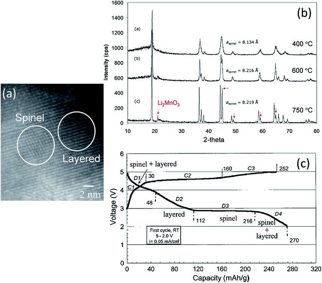 | ||
Fig. 10 (a) TEM image of 0.7Li2MnO3·0.3Li4Mn5O12 prepared at 400 °C, (b) XRD patterns of 0.7Li2MnO3·0.3Li4Mn5O12 (Li![[thin space (1/6-em)]](https://www.rsc.org/images/entities/char_2009.gif) : :![[thin space (1/6-em)]](https://www.rsc.org/images/entities/char_2009.gif) Mn = 1.2 Mn = 1.2![[thin space (1/6-em)]](https://www.rsc.org/images/entities/char_2009.gif) : :![[thin space (1/6-em)]](https://www.rsc.org/images/entities/char_2009.gif) 1) as a function of synthesis temperature, and (c) voltage profile of a Li/0.7Li2MnO3·0.3Li4Mn5O12 (750 °C) cell on initial charge–discharge cycle (reproduced with permission from Electrochemical Communications, Johnson et al.128). 1) as a function of synthesis temperature, and (c) voltage profile of a Li/0.7Li2MnO3·0.3Li4Mn5O12 (750 °C) cell on initial charge–discharge cycle (reproduced with permission from Electrochemical Communications, Johnson et al.128). | ||
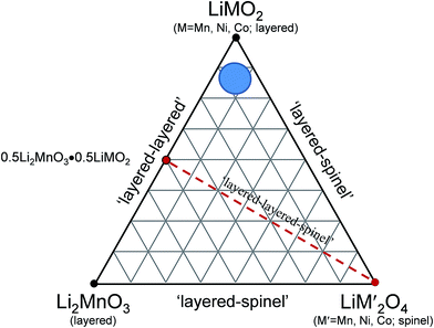
A compositional phase diagram of a three-component Li2MnO3–LiMO2–LiM′2O4 (‘layered–layered–spinel’) system shown in Fig. 11 highlights the wide compositional space that exists to exploit structurally integrated layered and spinel electrode materials. The Li2MnO3–LiMO2 tie-line reflects the composition of ‘layered–layered’ electrodes described in the preceding sections. Reducing the lithium content in the parent Li2MnO3–LiMO2 electrode material necessarily drives the composition of the electrode within the tie-triangle towards the spinel apex of the triangle. This strategy has been exploited to induce the formation of a stabilizing spinel component within layered or ‘layered–layered’ electrode structures during synthesis at elevated temperature.129,130
For example, reducing the amount of lithium required to synthesize Li2MnO3 and heating lithium-deficient precursors, Li2−xMnOδ (0 ≤ x ≤ 1.5), at 850 °C in air induces the formation of LiMn2O4, which requires some oxygen loss (δ) for charge compensation, as shown by XRD patterns (Fig. 12a) and the electrochemical profiles of Li/Li2−xMnOδ cells for x = 0, 0.5, 1.0, and 1.5 (Fig. 12b)159 (note that this system can be represented, alternatively, as yLi2MnO3·(1 − y)LiMn2O4 for y = 0, 0.2, 0.5, and 1.0, respectively). For x = 1 (i.e., 0.5Li2MnO3·0.5LiMn2O4), a TEM image of the product shows structurally integrated Li2MnO3 and LiMn2O4 domains, as expected, with the spinel component residing predominantly at the surface of the particles (Fig. 12c). Unlike the TEM image in Fig. 10a, which shows a Li2MnO3–Li4Mn5O12 composite structure synthesized at 400 °C with near perfect alignment of the close-packed planes of the two components, the image of the Li2MnO3–LiMn2O4 product in Fig. 12c shows a convoluted structure, which can likely be attributed to a mismatch in the lattice parameters and d-spacings of the layered Li2MnO3 and spinel LiMn2O4 components and to stacking fault disorder.
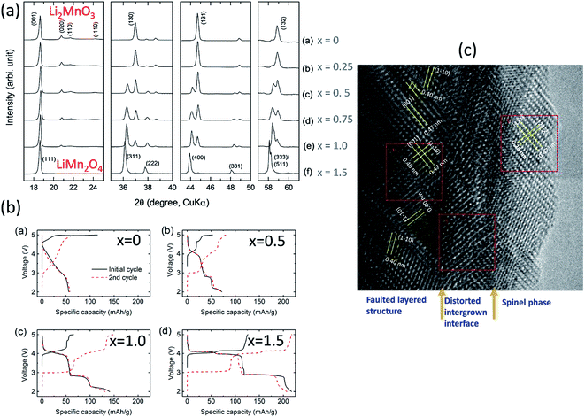 | ||
| Fig. 12 Effects of reducing the Li content in Li2−xMnOδ materials after heating to 850 °C: (a) XRD data, (b) electrochemical data, and (c) TEM image of Li2−xMnOδ (x = 1.0). | ||
Reducing the lithium content in the ‘layered–layered’ composition, 0.5Li2MnO3·0.5LiMn0.5Ni0.5O2 (in normalized notation Li1.5Mn0.75Ni0.25O2.5, or Li1.2Mn0.6Ni0.2O2), shows similar layered–spinel behavior as the Li2−xMnOδ system, described above. Increasing the lithium deficiency drives the composition of the electrode during high temperature synthesis towards the spinel composition LiMn1.5Ni0.5O4 because the Mn![[thin space (1/6-em)]](https://www.rsc.org/images/entities/char_2009.gif) :
:![[thin space (1/6-em)]](https://www.rsc.org/images/entities/char_2009.gif) Ni ratio (3
Ni ratio (3![[thin space (1/6-em)]](https://www.rsc.org/images/entities/char_2009.gif) :
:![[thin space (1/6-em)]](https://www.rsc.org/images/entities/char_2009.gif) 1) remains constant on the 0.5Li2MnO3·0.5LiMn0.5Ni0.5O2–LiMn1.5Ni0.5O4 tie-line.129 X-ray diffraction data and electrochemical profiles confirm increasing spinel-like character as the Li
1) remains constant on the 0.5Li2MnO3·0.5LiMn0.5Ni0.5O2–LiMn1.5Ni0.5O4 tie-line.129 X-ray diffraction data and electrochemical profiles confirm increasing spinel-like character as the Li![[thin space (1/6-em)]](https://www.rsc.org/images/entities/char_2009.gif) :
:![[thin space (1/6-em)]](https://www.rsc.org/images/entities/char_2009.gif) transition metal ratio in the parent ‘layered–layered’ electrode is reduced from x = 1 to x = 0 in x(Li2MnO3·0.5LiMn0.5Ni0.5O2)·(1 − x)LiMn1.5Ni0.5O4.129
transition metal ratio in the parent ‘layered–layered’ electrode is reduced from x = 1 to x = 0 in x(Li2MnO3·0.5LiMn0.5Ni0.5O2)·(1 − x)LiMn1.5Ni0.5O4.129
A study by Long et al. of the compositional, structural, and electrochemical features of spinel-stabilized ‘layered–layered’ xLi2MnO3·(1 − x)LiMO2 (M = Mn, Ni, Co) electrodes has revealed intriguing features of ‘layered–layered–spinel’ electrode materials.130 Compounds in the xLi2MnO3·(1 − x)LiMnyNiyCo1−2yO2 system for x = 0.25 and x = 0.33 were selected for this study. The cobalt content, 1 − 2y, was varied over the range 0.125 ≤ y ≤ 0.375 while keeping a constant Mn![[thin space (1/6-em)]](https://www.rsc.org/images/entities/char_2009.gif) :
:![[thin space (1/6-em)]](https://www.rsc.org/images/entities/char_2009.gif) Ni ratio of 1
Ni ratio of 1![[thin space (1/6-em)]](https://www.rsc.org/images/entities/char_2009.gif) :
:![[thin space (1/6-em)]](https://www.rsc.org/images/entities/char_2009.gif) 1. ‘Layered–layered–spinel’ products with a targeted spinel content of 6%, 15%, and 25% were synthesized from metal oxalate precursors by reducing the Li content in a parent ‘layered–layered’ composition by the appropriate amount. Fig. 13 shows, for x = 0.25 and y = 0.375, the impact of reducing the lithium content on the electrochemical capacity (in mA h g−1) after an initial ‘activation’ charge to 4.6 V and subsequent discharge to 2.0 V. Also shown is the first-cycle efficiency. The capacity of the parent 0.25Li2MnO3·0.75LiMn0.375Ni0.375Co0.250O2 electrode (in normalized notation, Li1.25Mn0.531Ni0.281Co0.187O2.25) increases from 208 to 212 mA h g−1 when the amount of lithium in the parent electrode is reduced to target a 6% spinel content. Increasing the targeted spinel content results in a decline in capacity, but it increases the first-cycle efficiency because, unlike a discharged layered LiMO2 component, a charged spinel component (e.g., Li1+xMn2−xO4) in the parent electrode can accommodate one lithium ion per formula unit. This electrochemical behavior is consistent with reports of other lithium- and manganese-rich ‘layered–layered–spinel’ electrode compositions.129,130,160
1. ‘Layered–layered–spinel’ products with a targeted spinel content of 6%, 15%, and 25% were synthesized from metal oxalate precursors by reducing the Li content in a parent ‘layered–layered’ composition by the appropriate amount. Fig. 13 shows, for x = 0.25 and y = 0.375, the impact of reducing the lithium content on the electrochemical capacity (in mA h g−1) after an initial ‘activation’ charge to 4.6 V and subsequent discharge to 2.0 V. Also shown is the first-cycle efficiency. The capacity of the parent 0.25Li2MnO3·0.75LiMn0.375Ni0.375Co0.250O2 electrode (in normalized notation, Li1.25Mn0.531Ni0.281Co0.187O2.25) increases from 208 to 212 mA h g−1 when the amount of lithium in the parent electrode is reduced to target a 6% spinel content. Increasing the targeted spinel content results in a decline in capacity, but it increases the first-cycle efficiency because, unlike a discharged layered LiMO2 component, a charged spinel component (e.g., Li1+xMn2−xO4) in the parent electrode can accommodate one lithium ion per formula unit. This electrochemical behavior is consistent with reports of other lithium- and manganese-rich ‘layered–layered–spinel’ electrode compositions.129,130,160
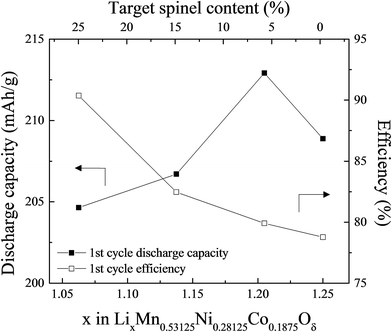 | ||
| Fig. 13 The effect of varying the lithium content in 0.25Li2MnO3·0.75LiMn0.375Ni0.375Co0.250O2, i.e., x in LixMn0.531Ni0.281Co0.188Oδ (reproduced with permission from J. Electrochem. Soc., Long et al.130 Copyright 2014, The Electrochemical Society). | ||
With the above-mentioned electrochemical data in mind, the current strategy at Argonne National Laboratory is to use a bottom-up strategy to develop ‘layered–layered–spinel’ materials that can deliver a stable capacity of at least 200 mA h g−1 when cycled below 4.5 V, which would make them competitive with layered Ni-rich systems.150 Approaches are being sought to overcome electrode surface and electrolyte instabilities and capacity fade (for example, by using effective surface coatings), which would allow ‘layered–layered–spinel’ electrodes, when charged repeatedly to 4.6 V, to deliver close to their theoretical capacity based on the redox reactions of the transition metal ions alone (∼250 mA h g−1).
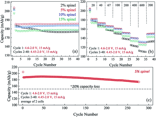
The impact of lowering the lithium content in ‘layered–layered’ electrodes on their capacity, cycling stability, and rate performance is highlighted in Fig. 14.150 For these experiments, lithium-deficient 0.25Li2MnO3·0.75LiMn0.375Ni0.375Co0.250O2 materials were prepared at Argonne's Materials Engineering and Research Facility to target a spinel content of 2, 5, 10, and 15% in the ‘layered–layered–spinel’ products. Lithium coin cells containing these materials were activated on the initial charge/discharge cycle (4.6–2.0 V) and subsequently cycled between 4.45 and 2.0 V at a low rate (15 mA g−1; ∼C/12). Fig. 14a shows that a maximum capacity is obtained when the targeted spinel content is 5–10%, consistent with the capacity vs. composition plot of cells with 0.25Li2MnO3·0.75LiMn0.375Ni0.375Co0.250O2 electrodes (Fig. 13). Fig. 14a also highlights the large decline in capacity for electrodes with 15% spinel content, and the poor capacity retention on cycling for electrodes with 2% spinel content. Of particular significance is that electrodes with 5–10% spinel are also more tolerant to higher rates than the 2% spinel electrode (Fig. 14b). This finding suggests that the spinel component may reside predominantly at the surface of the ‘layered–layered–spinel’ electrode particles, thereby stabilizing the electrode/electrolyte interface and providing good capacity retention on long-term cycling (275 cycles, Fig. 14c).
As shown in Fig. 15a and b, high-resolution (synchrotron) XRD and TEM data of a ‘layered–layered–spinel’ product with a targeted 15% spinel content, derived from a lithium-deficient 0.25Li2MnO3·0.75LiMn0.375Ni0.375Co0.250O2 parent composition, provided unequivocal evidence of a spinel component embedded within the layered structure (Fig. 15a and b).130 Of particular significance is that elemental mapping of the sample (Fig. 15c) by electron energy loss spectroscopy (EELS) indicated that regions rich in Mn and Ni adopt a spinel configuration, while regions rich in cobalt have a layered configuration. The data emphasize the complexity and inhomogeneity of these materials and the tendency to form thermodynamically favored configurations or to phase segregate on cooling the samples from the high temperature at which they are synthesized (typically 850–900 °C) to room temperature, consistent with data reported by Bareno et al.135 and Long et al.134 for ‘layered–layered’ electrodes in the Li2MnO3–LiCoO2 system. A question that remains to be answered is: when synthesizing ‘layered–layered–spinel’ structures, at what lithium concentration do the transition metal ions start diffusing into the lithium-rich layers to provide a spinel character to the electrode structure, rather than maintain a layered configuration in which the lithium deficiency is compensated by oxidation state changes on the transition metal ions? In this respect, recent structural refinements of lithium-deficient 0.25Li2MnO3·0.75LiMn0.375Ni0.375Co0.250O2 electrodes with synchrotron XRD data have revealed that reducing the lithium content does not immediately induce spinel formation. The lattice parameter of the cubic spinel component that ultimately forms is 8.145 Å, which is coincidentally close to that expected for lithium–manganese-oxide spinels, such as Li4Mn5O12,55 and probably cobalt- and/or nickel-substituted derivatives.161
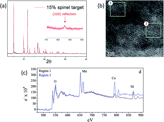 | ||
| Fig. 15 (a) High-resolution XRD pattern, (b) TEM image, and (c) EELS data of a lithium-deficient 0.25Li2MnO3·0.75LiMn0.375Ni0.375Co0.250O2 electrode targeting 15% spinel content (reproduced with permission from J. Electrochem. Soc., Long et al.130 Copyright 2014, The Electrochemical Society). | ||
Coatings and surface treatments
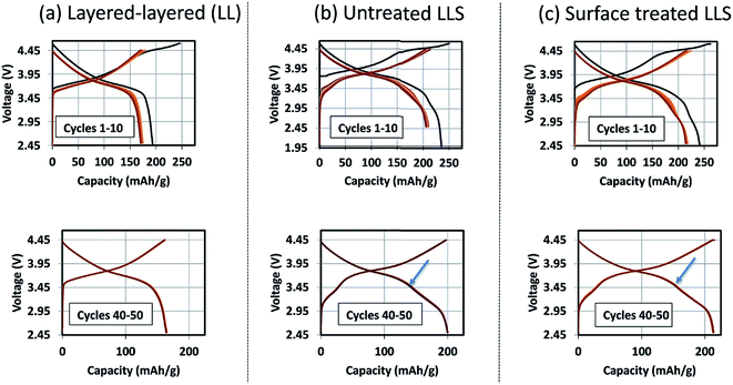
The formation of protective solid-electrolyte interphase (SEI) layers at the surface of lithium-ion battery electrodes that function outside the stability window of organic electrolyte solvents, particularly lithiated graphite (LiC6) anodes that operate at a potential of ∼100 mV above metallic lithium, is a well-known and studied phenomenon;162 without it, lithium-ion cells would not work. Unprotected lithium–metal-oxide cathodes that are electrochemically active above the upper stability limit of the electrolyte (∼4 V vs. Li0) also tend to suffer from interfacial electrode/electrolyte side reactions. These reactions can lead to structural decay, metal dissolution, oxygen loss, lower capacity, a slower electrochemical reaction rate, and reduced operating life, all of which can severely compromise the energy and power output of a lithium-ion cell. Numerous materials have been tried and tested as protective coatings for lithium–metal-oxide cathodes,163 many of which, for example, Al2O3,73,164 AlF3,165 ZrO2,166 Li2ZrO3,167 AlPO4,168,169 LiNiPO4,170 and graphene,77 can counter the above limitations to various extents.‘Layered–layered–spinel’ electrodes derived from a parent composition 0.25Li2MnO3·0.75LiMn0.375Ni0.375Co0.250O2, when activated between 4.6 and 2 V, and subsequently cycled between 4.45 and 2.5 V at 15 mA g−1, also benefit from surface treatment. Fig. 16 shows the electrochemical charge and discharge profiles of the first 10 cycles (top) and the 40th to 50th cycles (bottom) of lithium half cells with (a) a layered–layered 0.25Li2MnO3·0.75LiMn0.375Ni0.375Co0.250O2 electrode, (b) an untreated ‘layered–layered–spinel’ electrode with a targeted spinel content of 10% (based on inductively coupled plasma atomic emission spectroscopy (ICP-AES) analysis of the Li content), and (c) the ‘layered–layered–spinel’ electrode in (b) after a proprietary surface treatment. Despite several formation cycles required to stabilize the electrode reaction (Fig. 16a–c, top), all cells cycle thereafter with excellent capacity retention, with maximum capacity (∼215 mA h g−1) being generated by the surface-treated ‘layered–layered–spinel’ electrode (Fig. 16c, bottom). Note the distinct discontinuity (arrows) in the electrochemical profiles of cells containing the ‘layered–layered–spinel’ electrodes, tentatively attributed to structural and/or polarization effects, which could serve as an early end-of-life indicator for the cell.
Corresponding dQ/dV plots (Fig. 17) of the voltage–capacity data in Fig. 16 confirm the excellent cycling stability of untreated and surface-treated ‘layered–layered’ and ‘layered–layered–spinel’ electrodes derived from 0.25Li2MnO3·0.75LiMn0.375Ni0.375Co0.250O2. What is noteworthy about the dQ/dV plots is:
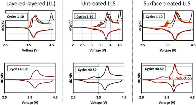 | ||
| Fig. 17 Corresponding dQ/dV plots of the voltage–capacity plots in Fig. 16, highlighting the electrochemical cycling stability of untreated and surface-treated ‘layered–layered’ and ‘layered–layered–spinel’ electrodes derived from 0.25Li2MnO3·0.75LiMn0.375Ni0.375Co0.250O2. | ||
(1) there is significantly less hysteresis and voltage fade than for the cell containing a ‘layered–layered’ cathode with higher lithium and manganese content, 0.5Li2MnO3·0.5LiMn0.375Ni0.375Co0.250O2 (Fig. 6);
(2) the Ni redox peak at approximately 3.7 V remains stable; and
(3) the small amount of capacity generated by voltage fade during the early cycles is delivered over a wide voltage range (approximately 3.4 to 2.7 V), implying that lithium insertion takes place in a highly complex ‘layered–spinel’ structure in which the interstitial site energies vary widely.
Nickel-rich layered electrode materials
Nickel-rich, layered electrodes, such as NCA (LiNi0.8Co0.15Al0.05O2) and NMC analogues LiNi0.8Mn0.1Co0.1O2 (‘811’) and LiNi0.6Mn0.2Co0.2O2 (‘622’), are currently considered next generation lithium-ion cathode materials.54,171 Gradient cathode designs, in which a high concentration of nickel decreases from the bulk to the surface of NMC particles are also being developed.172 However, the instability of tetravalent nickel and the possible release of oxygen in these electrodes at the top of charge introduce a safety risk, which can be reduced by increasing the manganese content. The electrochemical performance of a commercial, moderately nickel-rich NMC electrode, LiNi0.5Mn0.3Co0.2O2 (‘532’), was therefore compared with a moderately manganese-rich LLS ‘MNC’ electrode to assess their relative electrochemical behavior, the latter product being derived from a ‘layered–layered’ composition 0.25Li2MnO3·0.75LiMn0.375Ni0.375Co0.250O2 with a targeted 10% spinel content in which the Mn![[thin space (1/6-em)]](https://www.rsc.org/images/entities/char_2009.gif) :
:![[thin space (1/6-em)]](https://www.rsc.org/images/entities/char_2009.gif) Ni
Ni![[thin space (1/6-em)]](https://www.rsc.org/images/entities/char_2009.gif) :
:![[thin space (1/6-em)]](https://www.rsc.org/images/entities/char_2009.gif) Co ratio is 5.3
Co ratio is 5.3![[thin space (1/6-em)]](https://www.rsc.org/images/entities/char_2009.gif) :
:![[thin space (1/6-em)]](https://www.rsc.org/images/entities/char_2009.gif) 2.8
2.8![[thin space (1/6-em)]](https://www.rsc.org/images/entities/char_2009.gif) :
:![[thin space (1/6-em)]](https://www.rsc.org/images/entities/char_2009.gif) 1.9, i.e., close to ‘532’ (Fig. 18).173 In these tests, the nickel-rich Li/NMC cells were charged and discharged continuously between 4.45 and 2.5 V, whereas the manganese-rich Li/MNC cells (referenced as LLS in Fig. 18) were subjected to one activation cycle between 4.6 and 2.0 V, before continuous cycling between 4.45 and 2.5 V. Cells were cycled at a 15 mA g−1 rate and at 30 °C.
1.9, i.e., close to ‘532’ (Fig. 18).173 In these tests, the nickel-rich Li/NMC cells were charged and discharged continuously between 4.45 and 2.5 V, whereas the manganese-rich Li/MNC cells (referenced as LLS in Fig. 18) were subjected to one activation cycle between 4.6 and 2.0 V, before continuous cycling between 4.45 and 2.5 V. Cells were cycled at a 15 mA g−1 rate and at 30 °C.
Fig. 18a shows the first-cycle electrochemical profiles of the Li/NMC and Li/MNC (LLS) cells described above. The voltage profile of the NMC cell is consistent with a layered nickel-rich cathode structure, delivering approximately 190 mA h g−1 on the initial discharge. By contrast, the initial discharge capacity of the manganese-rich LLS cathode is considerably higher (238 mA h g−1), the additional capacity below 3.5 V being generated by the spinel-like component within the composite electrode structure. The electrochemical profiles of the Li/NMC and Li/MNC for cycles 2 and 50 are shown in Fig. 18b and c, respectively. Despite the more pronounced voltage fade of the manganese-rich LLS electrode, Li/MNC cells outperformed their nickel-rich NMC counterpart, both in terms of capacity and energy output. More specifically, the manganese-rich LLS electrodes delivered more than 200 mA h g−1 and an energy output of more than 750 W h kg−1 (based on the mass of the cathode alone) after 50 cycles, whereas the layered nickel-rich cathodes provided approximately 180 mA h g−1 and less than 700 W h kg−1, respectively. This result augurs well for further progress in exploiting manganese-rich LLS technology.
New approaches and future directions
Exploiting lithiated spinels as stabilizers for Li2MnO3–LiMO2 electrodes
Despite the advances that have been made in developing manganese-rich LLS electrode materials, Fig. 18 indicates that a LLS MNC ‘532’ electrode with 50% Mn still suffers from some structural decay and voltage fade on long term cycling. These limitations are thought to arise because MNC ‘532’ electrodes are not as effective in arresting transition metal migration as their layered nickel- and cobalt-rich counterparts. A recent strategy that has been adopted at Argonne to address this challenge is to use a cobalt-based lithiated spinel composition Li2[Co2−2xM2x]O4 (e.g., M = Ni, Al), alternatively LiCo1−xMxO2, rather than a stoichiometric, manganese-rich spinel, to stabilize high-capacity ‘layered–layered’ xLi2MnO3·(1 − x)LiMO2 electrodes.174 This approach is attractive for several reasons:(1) Like xLi2MnO3·(1 − x)LiMO2 materials, lithiated spinels Li2[Co2−2xM2x]O4 have close-packed structures with a rock-salt stoichiometry, making them compositionally, and potentially structurally, compatible with one another.
(2) Relative to manganese and nickel, cobalt has a lower propensity to migrate in a ccp oxygen lattice,103,175 thereby offering the possibility of mitigating voltage fade.
(3) Lithium extraction from a lithiated cobalt-rich spinel component, Li2−δ[Co2−2xM2x]O4, occurs at a significantly higher potential (∼3.6 V) than a lithiated manganese-oxide spinel analogue, Li2−δMn2O4 (∼2.9 V).
Limited research has been conducted on lithiated cobalt spinel materials, and substituted derivatives, since their discovery in the early 1990s.59,176 They are synthesized at a relatively low temperature (∼400 °C). The lithiated spinel Li2[Co2]O4 (or simply LiCoO2) has cubic symmetry (Fd![[3 with combining macron]](https://www.rsc.org/images/entities/char_0033_0304.gif) m) while its layered analogue has trigonal symmetry, R
m) while its layered analogue has trigonal symmetry, R![[3 with combining macron]](https://www.rsc.org/images/entities/char_0033_0304.gif) m (Fig. 19). Some of these early structural analyses of Li2[Co2]O4 were misleading because it had not been recognized that the atomic vector space of a cubic lithiated spinel structure is identical to that of a (hypothetical) layered LiCoO2 structure in which the oxygen array is ideally cubic-close-packed.60,61,177 In such an instance, the XRD patterns of a cubic lithiated spinel, Li2[Co2]O4, and a cubic layered LiCoO2 structure would be indistinguishable from one another, as shown in Fig. 19b and c.60 In practice, however, layered LiCoO2 deviates slightly from ideal cubic close packing, yielding a c/a ratio of 4.99, whereas cubic Li2[Co2]O4 has the ideal c/a ratio of 4.90 for a ccp structure;177 this difference separates the trigonal and cubic diffraction peaks from one another. Recent synchrotron XRD data and analyses have, however, confirmed the earlier conclusions that LiCoO2 prepared at 400 °C (LT-LiCoO2) has both layered- and lithiated-spinel character, and that 10% nickel substitution for cobalt (LT-LiCo0.9Ni0.1O2) essentially eliminates the layered LiCoO2 component from the structure (Fig. 20).174 Recent studies at Argonne have shown that other substituents such as Al can improve the cycling stability of these materials considerably; it has also been shown that Ni-substituted spinels can react with Li2MnO3 to form a series of xLi2MnO3·(1 − x)LiCo1−yNiyO2 compounds (0 ≤ x ≤ 0.2; 0 ≤ y ≤ 0.2), and that their electrochemical cycling stability is highly dependent on the values of x and y (Fig. 21).178 These cobalt-rich materials, in which the surplus lithium in the transition metal layer of the Li2MnO3 component and the cobalt in the lithium-rich layer of the lithiated spinel component play a stabilizing role, are under investigation as possible agents for minimizing the voltage fade and capacity loss of high-capacity, manganese-rich xLi2MnO3·(1 − x)LiMO2 (MNC) electrodes to an industrially acceptable level.
m (Fig. 19). Some of these early structural analyses of Li2[Co2]O4 were misleading because it had not been recognized that the atomic vector space of a cubic lithiated spinel structure is identical to that of a (hypothetical) layered LiCoO2 structure in which the oxygen array is ideally cubic-close-packed.60,61,177 In such an instance, the XRD patterns of a cubic lithiated spinel, Li2[Co2]O4, and a cubic layered LiCoO2 structure would be indistinguishable from one another, as shown in Fig. 19b and c.60 In practice, however, layered LiCoO2 deviates slightly from ideal cubic close packing, yielding a c/a ratio of 4.99, whereas cubic Li2[Co2]O4 has the ideal c/a ratio of 4.90 for a ccp structure;177 this difference separates the trigonal and cubic diffraction peaks from one another. Recent synchrotron XRD data and analyses have, however, confirmed the earlier conclusions that LiCoO2 prepared at 400 °C (LT-LiCoO2) has both layered- and lithiated-spinel character, and that 10% nickel substitution for cobalt (LT-LiCo0.9Ni0.1O2) essentially eliminates the layered LiCoO2 component from the structure (Fig. 20).174 Recent studies at Argonne have shown that other substituents such as Al can improve the cycling stability of these materials considerably; it has also been shown that Ni-substituted spinels can react with Li2MnO3 to form a series of xLi2MnO3·(1 − x)LiCo1−yNiyO2 compounds (0 ≤ x ≤ 0.2; 0 ≤ y ≤ 0.2), and that their electrochemical cycling stability is highly dependent on the values of x and y (Fig. 21).178 These cobalt-rich materials, in which the surplus lithium in the transition metal layer of the Li2MnO3 component and the cobalt in the lithium-rich layer of the lithiated spinel component play a stabilizing role, are under investigation as possible agents for minimizing the voltage fade and capacity loss of high-capacity, manganese-rich xLi2MnO3·(1 − x)LiMO2 (MNC) electrodes to an industrially acceptable level.
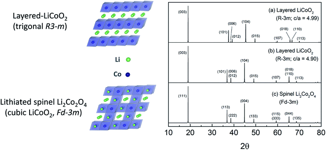 | ||
Fig. 19 Layered–spinel LiCoO2 structural anomaly: simulated XRD patterns of (a) layered-LiCoO2 structure (R![[3 with combining macron]](https://www.rsc.org/images/entities/char_0033_0304.gif) m, c/a = 4.99), (b) hypothetical layered structure with ideal cubic-close-packed oxygen array (R m, c/a = 4.99), (b) hypothetical layered structure with ideal cubic-close-packed oxygen array (R![[3 with combining macron]](https://www.rsc.org/images/entities/char_0033_0304.gif) m, c/a = 4.90), and (c) a cubic lithiated spinel, Li2[Co2]O4 (Fd m, c/a = 4.90), and (c) a cubic lithiated spinel, Li2[Co2]O4 (Fd![[3 with combining macron]](https://www.rsc.org/images/entities/char_0033_0304.gif) m), showing identical patterns to those of (b) and (c) (reproduced with permission from ACS Appl. Mater. Interfaces, Lee et al.174). m), showing identical patterns to those of (b) and (c) (reproduced with permission from ACS Appl. Mater. Interfaces, Lee et al.174). | ||
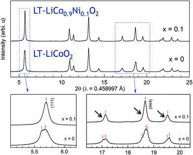 | ||
| Fig. 20 Synchrotron XRD patterns of LT-LiCo1−xNixO2 (x = 0 and 0.1) (reproduced with permission from ACS Appl. Mater. Interfaces, Lee et al.174). | ||
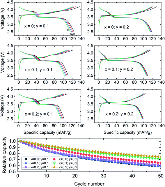 | ||
| Fig. 21 Voltage profiles of ‘layered–spinel’ Li/xLi2MnO3·(1 − x)LiCo1−yNiyO2 cells (0 ≤ x ≤ 0.2; 0 ≤ y ≤ 0.2) cycled between 2.5 and 4.2 V vs. Li at a current rate of 15 mA g−1. | ||
Exploiting oxygen redox reactions in high-capacity Li2MnO3-stabilized electrodes
It is now well known that anomalously high capacities can be derived from lithium- and manganese-rich electrodes by activating the electrodes through oxygen loss at potentials above 4.5 V, as described earlier.139–142 Intensive studies have been undertaken in recent years to understand and exploit electrochemically induced oxygen redox reactions in lithium metal oxides, such as Li2MO3 (Li2O·MO2) (M = Ru, Ir),143,179–181 Li5FeO4 (5Li2O·Fe2O3),182,183 and xLi2MnO3·(1 − x)LiMO2 (alternatively, x[Li2O·MnO2]·(1 − x)LiMO2) materials,123,124,184 all of which can be regarded as having Li2O-stabilized structures. Although some reversible (O2n−) redox behavior has been observed in these materials, it can push the structural stability of the electrode to the limit such that there is competition between the O2−/O22− anionic redox reaction and oxygen loss (O2), particularly at the electrode surface. It has been reported that oxygen loss is preceded by a shortening of the O–O bond in Li2IrO3,143 while first principles molecular dynamics simulations predict that O–O dimerization occurs in xLi2MnO3·(1 − x)LiMO2 systems.124 Both processes would result in a displacement of the oxygen ions from their close-packed positions in the parent electrode structure. In this respect, a recent XRD refinement of a 0.4Li2MnO3·0.6LiMn0.5Ni0.5O2 electrode using synchrotron data (Fig. 22a) revealed that, on the initial charge of a Li/0.4Li2MnO3·0.6LiMn0.5Ni0.5O2 cell to 4.7 V, the oxygen site occupancy decreased from 0.99 after ∼200 mA h g−1 of capacity had been withdrawn from the electrode (Fig. 22b) to 0.91 at the top of charge (∼280 mA h g−1), and that on the subsequent discharge to 2.5 V the site occupancy increased from 0.91 to ∼0.95.147 Similar behavior was observed on the second cycle (Fig. 22c) with improved coulombic efficiency. The study also revealed that diffraction peaks characteristic of the Li2MnO3 component disappeared during the initial charge and reappeared during discharge, consistent with changes in Mn–O correlations (observed by X-ray absorption spectroscopy) and a partially reversible lithium and oxygen displacement process. The data provide some hope that, with time, control of these anionic redox processes may become possible and lead to the successful exploitation of reversible oxygen electrochemistry, even if only to a limited extent, in lithium-ion cathode technology.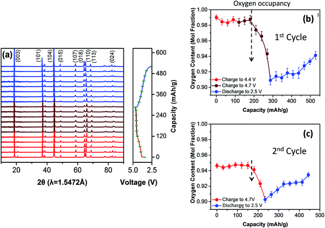 | ||
| Fig. 22 (a) Synchrotron XRD data and (b, c) variation of the oxygen site occupancy in a 0.4Li2MnO3·0.6LiMn0.5Ni0.5O2 electrode during the first two cycles of a lithium cell when charged and discharged between 4.7 and 2.5 V (reproduced with permission from Nano Energy, Yoon et al.147). | ||
Concluding remarks
Today's lithium-ion battery cathodes are dominated by cobalt- and nickel-rich materials, such as LiCoO2 (LCO) and LiNi0.8Co0.15Al0.05O2 (NCA), whereas manganese-based systems, such as the spinel LiMn2O4 (LMO) and LiNi0.33Mn0.33Co0.0.33O2 (NMC) play a relatively minor role in the market. Advances in cathode performance and cell energy density are likely to be made incrementally by improving the composition and structural design of lithium–metal-oxide materials and stabilized surfaces. Nickel-rich cathodes, such as NCA and NMC (e.g., ‘811’ and ‘622’), are currently in vogue but suffer from high cost and have potential safety concerns relative to manganese-rich materials. On the other hand, manganese-based cathodes such as LiMn2O4 and NMC (‘333’) will continue to serve the market, notably in the transportation sector for all-electric and hybrid-electric vehicles. The need to buffer cost when the prices of cobalt and nickel fluctuate to high values motivates and justifies further R&D of the manganese-rich high-voltage spinel, LiMn1.5Ni0.5O4, and lithium- and manganese-rich (Li2MnO3-stabilized) materials such as the ‘layered–layered’ and ‘layered–layered–spinel’ systems discussed in this paper.Statement of contributions
M. M. Thackeray – main author of this review and contributor to all aspects herein. J. R. Croy – co-author of text and author/contributor to data presented in Fig. 4, 7, 8, 13, 14–20. E. Lee – co-author of text and author/contributor to data presented in Fig. 1, 3, 6, 12,19–21. A. Gutierrez – co-author and contributor/author to data presented in Fig. 16–18. M. He – co-author and contributor/author to data presented in Fig. 16–18. J.-S. Park − co-author and contributor/author to data presented in Fig. 6, 7, 11, 13–15, and 19. B. T. Yonemoto – co-author and contributor/author to data presented in Fig. 11, 14, 16, and 17. B. R. Long – co-author and contributor/author to data presented in Fig. 3, 7, 13–15. J. D. Blauwkamp – co-author and contributor/author to data presented in Fig. 12, 19–21. C. S. Johnson – co-author and contributor/author to data presented in Fig. 1, 2, 5, and 10. Y. Shin – co-author and contributor/author to data presented in Fig. 14, 16, and 18. W. I. F. David – co-author and sole author of the work presented in Fig. 9.Conflicts of interest
There are no conflicts of interest to declare.Acknowledgements
Support from the Office of Vehicle Technologies of the U.S. Department of Energy, particularly from Tien Duong, David Howell, and Peter Faguy is gratefully acknowledged. The submitted manuscript has been created by UChicago Argonne, LLC, Operator of Argonne National Laboratory (“Argonne”). Argonne, a U.S. Department of Energy Office of Science laboratory, is operated under Contract No. DE-AC02-06CH11357. The U.S. Government retains for itself, and others acting on its behalf, a paid-up, nonexclusive, irrevocable worldwide license in said article to reproduce, prepare derivative works, distribute copies to the public, and perform publicly and display publicly, by or on behalf of the Government.References
- J. E. Post, Proc. Natl. Acad. Sci. U. S. A., 1999, 96, 3447–3454 CrossRef.
- Y. Chabre and J. Pannetier, Prog. Solid State Chem., 1995, 23, 1–130 CrossRef.
- M. M. Thackeray, Prog. Solid State Chem., 1997, 25, 1–71 CrossRef.
- D. Linden and T. B. Reddy, Handbook of Batteries, McGraw-Hill, New York, 3rd edn, 2001 Search PubMed.
- P. A. Marsal, K. Kordesch and L. F. Urry, US Pat., 2960558, 1960.
- J. Brenet and P. Malessan, C. R. Acad. Sci., 1956, 242, 3064–3066 Search PubMed.
- K. Neumann and W. Fink, Z. Elektrochem., 1958, 62, 114–122 Search PubMed.
- W. C. Vosburgh, J. Electrochem. Soc., 1959, 106, 839 CrossRef.
- P. Brouillet, A. Grund, F. Jolas and R. Mellet, C. R. Acad. Sci., 1963, 257, 3390 Search PubMed.
- A. Kozawa and R. A. Powers, J. Electrochem. Soc., 1966, 113, 870–878 CrossRef.
- K. J. Vetter, Z. Elektrochem., 1962, 66, 577–586 Search PubMed.
- J. O. Besenhard, Carbon, 1976, 14, 111–115 CrossRef.
- M. Zanini, S. Basu and J. E. Fischer, Carbon, 1978, 16, 211–212 CrossRef.
- S. Basu, C. Zeller, P. J. Flanders, C. D. Fuerst, W. D. Johnson and J. E. Fischer, Mater. Sci. Eng., 1979, 38, 275–283 CrossRef.
- M. S. Dresselhaus and G. Dresselhaus, Adv. Phys., 1981, 30, 139–326 CrossRef.
- H. Ikeda, K. Narukawa and H. Nakashima, Jpn. Pat., 57-208079, 1982.
- S. Basu, US Pat., 4304825, 1981.
- S. Basu, US Pat., 4423125, 1983.
- M. S. Whittingham, US Pat., 4009052, 1977.
- M. S. Whittingham, Science, 1976, 192, 1126–1127 Search PubMed.
- M. S. Whittingham, Prog. Solid State Chem., 1978, 12, 41–99 CrossRef.
- J. B. Goodenough and K. Mizuchima, US Pat., 4302518, 1981.
- K. Mizushima, P. C. Jones, P. J. Wiseman and J. B. Goodenough, Mater. Res. Bull., 1980, 15, 783–789 CrossRef.
- M. M. Thackeray and J. B. Goodenough, US Pat., 4507371, 1983.
- M. M. Thackeray, W. I. F. David, P. G. Bruce and J. B. Goodenough, Mater. Res. Bull., 1983, 18, 461–472 CrossRef.
- M. M. Thackeray, P. J. Johnson, L. A. de Picciotto, P. G. Bruce and J. B. Goodenough, Mater. Res. Bull., 1984, 19, 179–187 CrossRef.
- K. Kordesch, J. Gsellmann, M. Peri, K. Tomantschger and R. Chemelli, Electrochim. Acta, 1981, 26, 1495–1504 CrossRef.
- R. Patrice, B. Gerand, J. B. Leriche, L. Seguin, E. Wang, R. Moses, K. Brandt and J. M. Tarascon, J. Electrochem. Soc., 2001, 148, A448–A455 CrossRef.
- M. A. Dzieciuch, N. Gupta and H. S. Wroblowa, J. Electrochem. Soc., 1988, 135, 2415–2418 CrossRef.
- F. R. McLarnon and E. J. Cairns, J. Electrochem. Soc., 1991, 138, 645–664 CrossRef.
- T. C. Adler, F. R. Mclarnon and E. J. Cairns, J. Electrochem. Soc., 1993, 140, 289–294 CrossRef.
- N. D. Ingale, J. W. Gallaway, M. Nyce, A. Couzis and S. Banerjee, J. Power Sources, 2015, 276, 7–18 CrossRef.
- T. Hirai and I. Tari, Prog. Batteries Sol. Cells, 1980, 3, 157 Search PubMed.
- H. Ikeda, T. Saito and H. Tamura, Proc. Manganese Dioxide Symposium, 1975, vol. 1, p. 384 Search PubMed.
- R. J. Brodd, A. Kozawa and K. V. Kordesch, J. Electrochem. Soc., 1978, 125, C271–C283 CrossRef.
- H. Ikeda, M. Hara and S. Narukawa, US Pat., 4133856, 1979.
- W. I. F. David, M. M. Thackeray, P. G. Bruce and J. B. Goodenough, Mater. Res. Bull., 1984, 19, 99–106 CrossRef.
- T. Nohma, T. Saito, N. Furukawa and H. Ikeda, J. Power Sources, 1989, 26, 389–396 CrossRef.
- T. Nohma, Y. Yamamoto, K. Nishio, I. Nakane and N. Furukawa, J. Power Sources, 1990, 32, 373–379 CrossRef.
- M. M. Thackeray, M. H. Rossouw, A. de Kock, A. P. de la Harpe, R. J. Gummow, K. Pearce and D. C. Liles, J. Power Sources, 1993, 43–44, 289–300 CrossRef.
- E. Levi, E. Zinigrad, H. Teller, M. D. Levi, D. Aurbach, E. Mengeritsky, E. Elster, P. Dan, E. Granot and H. Yamin, J. Electrochem. Soc., 1997, 144, 4133–4141 CrossRef.
- M. H. Rossouw, D. C. Liles, M. M. Thackeray, W. I. F. David and S. Hull, Mater. Res. Bull., 1992, 27, 221–230 CrossRef.
- P. Botkovitz, P. Deniard, M. Tournoux and R. Brec, J. Power Sources, 1993, 44, 657–665 CrossRef.
- C. S. Johnson, D. W. Dees, M. F. Mansuetto, M. M. Thackeray, D. R. Vissers, D. Argyriou, C. K. Loong and L. Christensen, J. Power Sources, 1997, 68, 570–577 CrossRef.
- Z. Z. Yang, D. C. Ford, J. S. Park, Y. Ren, S. Kim, H. Kim, T. T. Fister, M. K. Y. Chan and M. M. Thackeray, Chem. Mater., 2017, 29, 1507–1517 CrossRef.
- Z. Z. Yang, L. Trahey, Y. Ren, M. K. Y. Chan, C. K. Lin, J. Okasinski and M. M. Thackeray, J. Mater. Chem. A, 2015, 3, 7389–7398 Search PubMed.
- M. H. Rossouw and M. M. Thackeray, US Pat., 5166012, 1992.
- A. Debart, A. J. Paterson, J. Bao and P. G. Bruce, Angew. Chem., Int. Ed., 2008, 47, 4521–4524 CrossRef PubMed.
- M. M. Thackeray, M. K. Y. Chan, L. Trahey, S. Kirklin and C. Wolverton, J. Phys. Chem. Lett., 2013, 4, 3607–3611 CrossRef.
- M. S. Whittingham, Chem. Rev., 2004, 104, 4271–4301 CrossRef PubMed.
- J. B. Goodenough and Y. Kim, Chem. Mater., 2010, 22, 587–603 CrossRef.
- N. Nitta, F. X. Wu, J. T. Lee and G. Yushin, Mater. Today, 2015, 18, 252–264 CrossRef.
- M. Brand, S. Glaser, J. Geder, S. Menacher, S. Obpacher, A. Jossen and D. Quinger, 2013 World Electric Vehicle Symposium and Exhibition (EVS27), Barcelona, Spain, 2013 Search PubMed.
- A. Manthiram, B. Song and W. Li, Energy Storage Materials, 2017, 6, 125–139 CrossRef.
- M. M. Thackeray, A. Dekock, M. H. Rossouw, D. Liles, R. Bittihn and D. Hoge, J. Electrochem. Soc., 1992, 139, 363–366 CrossRef.
- J. C. Hunter, J. Solid State Chem., 1981, 39, 142–147 CrossRef.
- A. R. Armstrong and P. G. Bruce, Nature, 1996, 381, 499–500 CrossRef.
- R. J. Gummow, D. C. Liles and M. M. Thackeray, Mater. Res. Bull., 1993, 28, 1249–1256 CrossRef.
- R. J. Gummow and M. M. Thackeray, Solid State Ionics, 1992, 53, 681–687 CrossRef.
- E. Rossen, J. N. Reimers and J. R. Dahn, Solid State Ionics, 1993, 62, 53–60 CrossRef.
- R. J. Gummow, D. C. Liles and M. M. Thackeray, Mater. Res. Bull., 1993, 28, 235–246 CrossRef.
- J. B. Goodenough, M. M. Thackeray, W. I. F. David and P. G. Bruce, Rev. Chim. Miner., 1984, 21, 435–455 Search PubMed.
- T. Ohzuku, M. Kitagawa and T. Hirai, J. Electrochem. Soc., 1990, 137, 769–775 CrossRef.
- C. Masquelier, M. Tabuchi, K. Ado, R. Kanno, Y. Kobayashi, Y. Maki, O. Nakamura and J. B. Goodenough, J. Solid State Chem., 1996, 123, 255–266 CrossRef.
- J. M. Tarascon, E. Wang, F. K. Shokoohi, W. R. McKinnon and S. Colson, J. Electrochem. Soc., 1991, 138, 2859–2864 CrossRef.
- J. M. Tarascon and D. Guyomard, J. Electrochem. Soc., 1991, 138, 2864–2868 CrossRef.
- M. M. Thackeray and R. J. Gummow, US Pat., 5316877, 1994.
- R. J. Gummow, A. de Kock and M. M. Thackeray, Solid State Ionics, 1994, 69, 59–67 CrossRef.
- Y. S. Lee, N. Kumada and M. Yoshio, J. Power Sources, 2001, 96, 376–384 CrossRef.
- R. Benedek and M. M. Thackeray, Electrochem. Solid-State Lett., 2006, 9, A265–A267 CrossRef.
- C. Zhan, J. Lu, A. J. Kropf, T. P. Wu, A. N. Jansen, Y. K. Sun, X. P. Qiu and K. Amine, Nat. Commun., 2013, 4, 2437 Search PubMed.
- T. F. Yi, Y. R. Zhu, X. D. Zhu, J. Shu, C. B. Yue and A. N. Zhou, Ionics, 2009, 15, 779–784 CrossRef.
- J.-S. Kim, C. S. Johnson, J. T. Vaughey, S. A. Hackney, K. A. Walz, W. A. Zeltner, M. A. Anderson and M. M. Thackeray, J. Electrochem. Soc., 2004, 151, A1755–A1761 CrossRef.
- S. W. Lee, K. S. Kim, H. S. Moon, H. J. Kim, B. W. Cho, W. I. Cho, J. B. Ju and J. W. Park, J. Power Sources, 2004, 126, 150–155 CrossRef.
- S. Lee, M. Jeong and J. Cho, Adv. Energy Mater., 2013, 3, 1623–1629 CrossRef.
- L. Jaber-Ansari, K. P. Puntambekar, S. Kim, M. Aykol, L. L. Luo, J. S. Wu, B. D. Myers, H. Iddir, J. T. Russell, S. J. Saldana, R. Kumar, M. M. Thackeray, L. A. Curtiss, V. P. Dravid, C. Wolverton and M. C. Hersam, Adv. Energy Mater., 2015, 5, 1500646 CrossRef.
- K. S. Chen, R. Xu, N. S. Luu, E. B. Secor, K. Hamamoto, Q. Q. Li, S. Kim, V. K. Sangwan, I. Balla, L. M. Guiney, J. W. T. Seo, X. K. Yu, W. W. Liu, J. S. Wu, C. Wolverton, V. P. Dravid, S. A. Barnett, J. Lu, K. Amine and M. C. Hersam, Nano Lett., 2017, 17, 2539–2546 CrossRef PubMed.
- S. B. Chikkannanavar, D. M. Bernardi and L. Y. Liu, J. Power Sources, 2014, 248, 91–100 CrossRef.
- K. Amine, H. Tukamoto, H. Yasuda and Y. Fujita, J. Electrochem. Soc., 1996, 143, 1607–1613 CrossRef.
- E.-S. Lee, K.-W. Nam, E. Hu and A. Manthiram, Chem. Mater., 2012, 24, 3610–3620 CrossRef.
- A. D. Robertson and P. G. Bruce, Chem. Mater., 2003, 15, 1984–1992 CrossRef.
- L. A. de Picciotto, K. T. Adendorff, D. C. Liles and M. M. Thackeray, Solid State Ionics, 1993, 62, 297–307 CrossRef.
- G. Pistoia, S. Panero, M. Tocci, R. V. Moshtev and V. Manev, Solid State Ionics, 1984, 13, 311–318 CrossRef.
- R. Benedek, M. M. Thackeray and L. H. Yang, J. Power Sources, 1999, 81, 487–490 CrossRef.
- P. Hovington, M. Lagace, A. Guerfi, P. Bouchard, A. Manger, C. M. Julien, M. Armand and K. Zaghib, Nano Lett., 2015, 15, 2671–2678 CrossRef PubMed.
- M. M. Thackeray, C. S. Johnson, J. T. Vaughey, N. Li and S. A. Hackney, J. Mater. Chem., 2005, 15, 2257–2267 RSC.
- M. M. Thackeray, S. H. Kang, C. S. Johnson, J. T. Vaughey, R. Benedek and S. A. Hackney, J. Mater. Chem., 2007, 17, 3112–3125 RSC.
- M. M. Thackeray and M. H. Rossouw, US Pat., 5153081, 1992.
- M. H. Rossouw, D. C. Liles and M. M. Thackeray, J. Solid State Chem., 1993, 104, 464–466 CrossRef.
- Y. Paik, C. P. Grey, C. S. Johnson, J. S. Kim and M. M. Thackeray, Chem. Mater., 2002, 14, 5109–5115 CrossRef.
- W. Tang, H. Kanoh, X. Yang and K. Ooi, Chem. Mater., 2000, 12, 3271–3279 CrossRef.
- M. H. Rossouw and M. M. Thackeray, Mater. Res. Bull., 1991, 26, 463–473 CrossRef.
- C. S. Johnson, S. D. Korte, J. T. Vaughey, M. M. Thackeray, T. E. Bofinger, Y. Shao-Horn and S. A. Hackney, J. Power Sources, 1999, 81, 491–495 CrossRef.
- P. Kalyani, S. Chitra, T. Mohan and S. Gopukumar, J. Power Sources, 1999, 80, 103–106 CrossRef.
- A. R. Armstrong, A. D. Robertson and P. G. Bruce, J. Power Sources, 2005, 146, 275–280 CrossRef.
- F. Capitaine, P. Gravereau and C. Delmas, Solid State Ionics, 1996, 89, 197–202 CrossRef.
- P. G. Bruce, A. R. Armstrong and R. L. Gitzendanner, J. Mater. Chem., 1999, 9, 193–198 RSC.
- J. Reed, G. Ceder and A. Van der Ven, Electrochem. Solid-State Lett., 2001, 4, A78–A81 CrossRef.
- C. Delmas, I. Saadoune and A. Rougier, J. Power Sources, 1993, 44, 595–602 CrossRef.
- C. Delmas, M. Menetrier, L. Croguennec, I. Saadoune, A. Rougier, C. Pouillerie, G. Prado, M. Grune and L. Fournes, Electrochim. Acta, 1999, 45, 243–253 CrossRef.
- E. Rossen, C. D. W. Jones and J. R. Dahn, Solid State Ionics, 1992, 57, 311–318 CrossRef.
- M. E. Spahr, P. Novak, B. Schnyder, O. Haas and R. Nesper, J. Electrochem. Soc., 1998, 145, 1113–1121 CrossRef.
- A. R. Armstrong, A. D. Robertson and P. G. Bruce, Electrochim. Acta, 1999, 45, 285–294 CrossRef.
- A. D. Robertson, A. R. Armstrong and P. G. Bruce, Chem. Mater., 2001, 13, 2380–2386 CrossRef.
- C. Storey, I. Kargina, Y. Grincourt, I. J. Davidson, Y. C. Yoo and D. Y. Seung, J. Power Sources, 2001, 97–8, 541–544 CrossRef.
- B. Ammundsen, J. Paulsen, I. Davidson, R. S. Liu, C. H. Shen, J. M. Chen, L. Y. Jang and J. F. Lee, J. Electrochem. Soc., 2002, 149, A431–A436 CrossRef.
- J. B. Goodenough, A. K. Padhi, K. S. Nanjundaswamy and C. Masquelier, US Pat., 5910382, 1999.
- A. K. Padhi, K. S. Nanjundaswamy and J. B. Goodenough, J. Electrochem. Soc., 1997, 144, 1188–1194 CrossRef.
- A. K. Padhi, K. S. Nanjundaswamy, C. Masquelier, S. Okada and J. B. Goodenough, J. Electrochem. Soc., 1997, 144, 1609–1613 CrossRef.
- L. A. de Picciotto and M. M. Thackeray, Solid State Ionics, 1986, 18–9, 773–777 CrossRef.
- G. G. Amatucci, J. M. Tarascon and L. C. Klein, J. Electrochem. Soc., 1996, 143, 1114–1123 CrossRef.
- J. N. Reimers and J. R. Dahn, J. Electrochem. Soc., 1992, 139, 2091–2097 CrossRef.
- M. M. Thackeray, C. S. Johnson, K. Amine and J. Kim, US Pat., 6677082, 2004.
- M. M. Thackeray, C. S. Johnson, K. Amine and J. Kim, US Pat., 6680143, 2004.
- J. S. Kim, C. S. Johnson and M. M. Thackeray, Electrochem. Commun., 2002, 4, 205–209 CrossRef.
- J.-S. Kim, C. S. Johnson, J. T. Vaughey, M. M. Thackeray, S. A. Hackney, W. Yoon and C. P. Grey, Chem. Mater., 2004, 16, 1996–2006 CrossRef.
- M. M. Thackeray, S. H. Kang, C. S. Johnson, J. T. Vaughey and S. A. Hackney, Electrochem. Commun., 2006, 8, 1531–1538 CrossRef.
- J. R. Croy, M. Balasubramanian, K. G. Gallagher and A. K. Burrell, Acc. Chem. Res., 2015, 48, 2813–2821 CrossRef PubMed.
- J. Wang, X. He, E. Paillard, N. Laszczynski, J. Li and S. Passerini, Adv. Energy Mater., 2016, 6, 1600906 CrossRef.
- J. M. Zheng, S. J. Myeong, W. R. Cho, P. F. Yan, J. Xiao, C. M. Wang, J. Cho and J. G. Zhang, Adv. Energy Mater., 2017, 7, 1601284 CrossRef.
- W. D. Li, B. H. Song and A. Manthiram, Chem. Soc. Rev., 2017, 46, 3006–3059 RSC.
- H. Iddir and R. Benedek, Chem. Mater., 2014, 26, 2407–2413 CrossRef.
- H. Iddir, J. Bareño and R. Benedek, J. Electrochem. Soc., 2016, 163, A1784–A1789 CrossRef.
- R. Benedek and H. Iddir, J. Phys. Chem. C, 2017, 121, 6492–6499 Search PubMed.
- E. Lee and K. A. Persson, Adv. Energy Mater., 2014, 4, 1400498 CrossRef.
- Y. Shin, H. Ding and K. A. Persson, Chem. Mater., 2016, 28, 2081–2088 CrossRef.
- S. Kim, M. Aykol, V. I. Hegde, Z. Lu, S. Kirklin, J. R. Croy, M. M. Thackeray and C. Wolverton, Energy Environ. Sci., 2017, 10, 2201–2211 Search PubMed.
- C. S. Johnson, N. Li, J. T. Vaughey, S. A. Hackney and M. M. Thackeray, Electrochem. Commun., 2005, 7, 528–536 CrossRef.
- S. H. Park, S. H. Kang, C. S. Johnson, K. Amine and M. M. Thackeray, Electrochem. Commun., 2007, 9, 262–268 CrossRef.
- B. R. Long, J. R. Croy, J. S. Park, J. G. Wen, D. J. Miller and M. M. Thackeray, J. Electrochem. Soc., 2014, 161, A2160–A2167 CrossRef.
- K. A. Jarvis, Z. Deng, L. F. Allard, A. Manthiram and P. J. Ferreira, Chem. Mater., 2011, 23, 3614–3621 CrossRef.
- J. Reed and G. Ceder, Electrochem. Solid-State Lett., 2002, 5, A145–A148 CrossRef.
- Y. Gao, K. Myrtle, M. J. Zhang, J. N. Reimers and J. R. Dahn, Phys. Rev. B, 1996, 54, 16670–16675 CrossRef.
- B. R. Long, J. R. Croy, F. Dogan, M. R. Suchomel, B. Key, J. Wen, D. J. Miller, M. M. Thackeray and M. Balasubramanian, Chem. Mater., 2014, 26, 3565–3572 CrossRef.
- J. Bareño, M. Balasubramanian, S. H. Kang, J. G. Wen, C. H. Lei, S. V. Pol, I. Petrov and D. P. Abraham, Chem. Mater., 2011, 23, 2039–2050 CrossRef.
- J. Choi and A. Manthiram, J. Electrochem. Soc., 2005, 152, A1714–A1718 CrossRef.
- K. Shizuka, T. Kobayashi, K. Okahara, K. Okamoto, S. Kanzaki and R. Kanno, J. Power Sources, 2005, 146, 589–593 CrossRef.
- S. H. Park, S. H. Kang, I. Belharouak, Y. K. Sun and K. Amine, J. Power Sources, 2008, 177, 177–183 CrossRef.
- Z. H. Lu, L. Y. Beaulieu, R. A. Donaberger, C. L. Thomas and J. R. Dahn, J. Electrochem. Soc., 2002, 149, A778–A791 CrossRef.
- Z. H. Lu and J. R. Dahn, J. Electrochem. Soc., 2002, 149, A815–A822 CrossRef.
- C. S. Johnson, J. S. Kim, C. Lefief, N. Li, J. T. Vaughey and M. M. Thackeray, Electrochem. Commun., 2004, 6, 1085–1091 CrossRef.
- A. R. Armstrong, M. Holzapfel, P. Novak, C. S. Johnson, S. H. Kang, M. M. Thackeray and P. G. Bruce, J. Am. Chem. Soc., 2006, 128, 8694–8698 CrossRef PubMed.
- E. McCalla, A. M. Abakumov, M. Saubanère, D. Foix, E. J. Berg, G. Rousse, M.-L. Doublet, D. Gonbeau, P. Novák, G. Van Tendeloo, R. Dominko and J.-M. Tarascon, Science, 2015, 350, 1516–1521 CrossRef PubMed.
- A. Grimaud, W. T. Hong, Y. Shao-Horn and J. M. Tarascon, Nat. Mater., 2016, 15, 121–126 CrossRef PubMed.
- D. H. Seo, J. Lee, A. Urban, R. Malik, S. Kang and G. Ceder, Nat. Chem., 2016, 8, 692–697 CrossRef PubMed.
- C. S. Johnson, N. Li, C. Lefief and M. M. Thackeray, Electrochem. Commun., 2007, 9, 787–795 CrossRef.
- S. Muhammad, H. Kim, Y. Kim, D. Kim, J. H. Song, J. Yoon, J.-H. Park, S.-J. Ahn, S.-H. Kang, M. M. Thackeray and W.-S. Yoon, Nano Energy, 2016, 21, 172–184 CrossRef.
- P. K. Nayak, J. Grinblat, M. Levi, E. Levi, S. Kim, J. W. Choi and D. Aurbach, Adv. Energy Mater., 2016, 6, 1502398 CrossRef.
- P. K. Nayak, J. Grinblat, E. Levi, T. R. Penki, M. Levi, Y.-K. Sun, B. Markovsky and D. Aurbach, ACS Appl. Mater. Interfaces, 2017, 9, 4309–4319 Search PubMed.
- J. R. Croy, J. S. Park, Y. Shin, B. T. Yonemoto, M. Balasubramanian, B. R. Long, Y. Ren and M. M. Thackeray, J. Power Sources, 2016, 334, 213–220 CrossRef.
- M. M. Thackeray, C. Wolverton and E. D. Isaacs, Energy Environ. Sci., 2012, 5, 7854–7863 Search PubMed.
- K. G. Gallagher, J. R. Croy, M. Balasubramanian, M. Bettge, D. P. Abraham, A. K. Burrell and M. M. Thackeray, Electrochem. Commun., 2013, 33, 96–98 CrossRef.
- J. R. Croy, K. G. Gallagher, M. Balasubramanian, Z. Chen, Y. Ren, D. Kim, S.-H. Kang, D. W. Dees and M. M. Thackeray, J. Phys. Chem. C, 2013, 117, 6525–6536 Search PubMed.
- W. I. F. David, unpublished work.
- G.-A. Nazri and G. Pistoia, Lithium Batteries: Science and Technology, Kluwer Academic Publishers, Massachusetts, 2003 Search PubMed.
- N. Leifer, F. Schipper, E. M. Erickson, C. Ghanty, M. Talianker, J. Grinblat, C. M. Julien, B. Markovsky and D. Aurbach, J. Phys. Chem. C, 2017, 121, 9120–9130 Search PubMed.
- M. H. Rossouw, A. Dekock, L. A. Depicciotto and M. M. Thackeray, Mater. Res. Bull., 1990, 25, 173–182 CrossRef.
- C. S. Johnson, S. H. Kang, J. T. Vaughey, S. V. Pol, M. Balasubramanian and M. M. Thackeray, Chem. Mater., 2010, 22, 1263–1270 CrossRef.
- E. Lee, J. S. Park, H. Kim, Q. Li, J. Wu, V. P. Dravid, J. Blauwkamp, J. Croy and M. M. Thackeray, DOE Vehicle Technologies Annual Merit Review, ES049, 2017 Search PubMed.
- D. Kim, G. Sandi, J. R. Croy, K. G. Gallagher, S. H. Kang, E. Lee, M. D. Slater, C. S. Johnson and M. M. Thackeray, J. Electrochem. Soc., 2013, 160, A31–A38 CrossRef.
- E. Lee, D. Ahn, J. S. Park, A. Gutierrez, M. He, D. Mohanty, A. Huq, Y. Ren, J. R. Croy and M. M. Thackeray, DOE Vehicle Technologies Annual Merit Review, BAT235 & BAT049, 2018 Search PubMed.
- E. Peled and S. Menkin, J. Electrochem. Soc., 2017, 164, A1703–A1719 CrossRef.
- C. Li, H. P. Zhang, L. J. Fu, H. Liu, Y. P. Wu, E. Rahm, R. Holze and H. Q. Wu, Electrochim. Acta, 2006, 51, 3872–3883 CrossRef.
- J. Liu and A. Manthiram, J. Mater. Chem., 2010, 20, 3961–3967 RSC.
- Y.-K. Sun, M.-J. Lee, C. S. Yoon, J. Hassoun, K. Amine and B. Scrosati, Adv. Mater., 2012, 24, 1192–1196 CrossRef PubMed.
- H. M. Wu, I. Belharouak, A. Abouimrane, Y. K. Sun and K. Amine, J. Power Sources, 2010, 195, 2909–2913 CrossRef.
- M. M. Thackeray, C. S. Johnson, J. S. Kim, K. C. Lauzze, J. T. Vaughey, N. Dietz, D. Abraham, S. A. Hackney, W. Zeltner and M. A. Anderson, Electrochem. Commun., 2003, 5, 752–758 CrossRef.
- J. Cho, T.-J. Kim, J. Kim, M. Noh and B. Park, J. Electrochem. Soc., 2004, 151, A1899–A1904 CrossRef.
- Q. Y. Wang, J. Liu, A. V. Murugan and A. Manthiram, J. Mater. Chem., 2009, 19, 4965–4972 RSC.
- S. H. Kang and M. M. Thackeray, Electrochem. Commun., 2009, 11, 748–751 CrossRef.
- Visual Capitalist, http://www.visualcapitalist.com/nickel-secret-driver-battery-revolution, accessed January 2018.
- Y.-K. Sun, Z. Chen, H.-J. Noh, D.-J. Lee, H.-G. Jung, Y. Ren, S. Wang, C. S. Yoon, S.-T. Myung and K. Amine, Nat. Mater., 2012, 11, 942–947 CrossRef PubMed.
- J. R. Croy, A. Gutierrez, E. Lee and M. M. Thackeray, Manganese-Rich Alternatives to Nickel-Rich NMC Cathodes, in preparation.
- E. Lee, J. Blauwkamp, F. C. Castro, J. Wu, V. P. Dravid, P. Yan, C. Wang, S. Kim, C. Wolverton, R. Benedek, F. Dogan, J. S. Park, J. R. Croy and M. M. Thackeray, ACS Appl. Mater. Interfaces, 2016, 8, 27720–27729 Search PubMed.
- J. Reed and G. Ceder, Chem. Rev., 2004, 104, 4513–4533 CrossRef PubMed.
- R. J. Gummow, M. M. Thackeray, W. I. F. David and S. Hull, Mater. Res. Bull., 1992, 27, 327–337 CrossRef.
- R. J. Gummow, D. C. Liles, M. M. Thackeray and W. I. F. David, Mater. Res. Bull., 1993, 28, 1177–1184 CrossRef.
- E. Lee, J. Blauwkamp, A. Gutierrez, M. He, J. Croy and M. M. Thackeray, Stabilizing Low Temperature LiCoO2 by Li2MnO3 and Ni Integration, in preparation.
- M. Sathiya, K. Ramesha, G. Rousse, D. Foix, D. Gonbeau, A. S. Prakash, M. L. Doublet, K. Hemalatha and J. M. Tarascon, Chem. Mater., 2013, 25, 1121–1131 CrossRef.
- M. Sathiya, G. Rousse, K. Ramesha, C. P. Laisa, H. Vezin, M. T. Sougrati, M. L. Doublet, D. Foix, D. Gonbeau, W. Walker, A. S. Prakash, M. Ben Hassine, L. Dupont and J. M. Tarascon, Nat. Mater., 2013, 12, 827–835 CrossRef PubMed.
- P. E. Pearce, A. J. Perez, G. Rousse, M. Saubanere, D. Batuk, D. Foix, E. McCalla, A. M. Abakumov, G. Van Tendeloo, M. L. Doublet and J. M. Tarascon, Nat. Mater., 2017, 16, 580–586 CrossRef PubMed.
- C. S. Johnson, S. H. Kang, J. T. Vaughey, S. V. Pol, M. Balasubramanian and M. M. Thackeray, Chem. Mater., 2010, 22, 1263–1270 CrossRef.
- C. Zhan, Z. Yao, J. Lu, L. Ma, V. A. Maroni, L. Li, E. Lee, E. E. Alp, T. Wu, J. Wen, Y. Ren, C. Johnson, M. M. Thackeray, M. K. Y. Chan, C. Wolverton and K. Amine, Nat. Energy, 2017, 2, 963–971 CrossRef.
- K. Luo, M. R. Roberts, N. Guerrini, N. Tapia-Ruiz, R. Hao, F. Massel, D. M. Pickup, S. Ramos, Y.-S. Liu, J. Guo, A. V. Chadwick, L. C. Duda and P. G. Bruce, J. Am. Chem. Soc., 2016, 138, 11211–11218 CrossRef PubMed.
Footnotes |
| † Current addresses: SAFT America, Cockeysville, Maryland 21030, USA. |
| ‡ Current addresses: Microvast Power Solutions, Inc., Orlando, Florida 32826, USA. |
| § Current addresses: BASF, Beachwood, Ohio 44122, USA. |
| ¶ Current addresses: Challenge Manufacturing, Grand Rapids, MI 49544. |
| This journal is © The Royal Society of Chemistry 2018 |


