 Open Access Article
Modelling nonlocal nonlinear spin dynamics in antiferromagnetic orthoferrites†
Yuichi
Saito
and
Rostislav V.
Mikhaylovskiy
 *
*
Department of Physics, Lancaster University, Bailrigg, Lancaster LA1 4YW, UK. E-mail: r.mikhaylovskiy@lancaster.ac.uk
First published on 6th April 2022
Abstract
Excitation with an ultrashort light pulse is arguably the only way to control spins in antiferromagnetic materials at both the nanoscale in space and ultrafast time scale. While recent experiments highlighted tantalising opportunities for spin switching and magnonics in antiferromagnets, the theoretical description of antiferromagnetic spin dynamics driven by strongly localised and ultrashort excitation is in its infancy. Here we report a theoretical model describing the nonlocal and nonlinear spin response to the excitation by light. We show that strongly localised ultrafast excitation can drive spin switching, which propagates in space and acts as a source of spin waves. Our theoretical formalism is readily available to describe current and future ultrafast spectroscopy experiments in antiferromagnets.
Introduction
Antiferromagnets, materials supporting magnetic ordering without net magnetization, are the most appealing media for future technologies in ultrafast and energy efficient data storage and computing, based on spintronics and magnonics.1,2 In particular, antiferromagnets have the magnetic resonance frequency in the sub-terahertz or terahertz (THz) region and therefore produce a much faster coherent response to external perturbation, compared to the conventional ferromagnets, whose resonance frequencies lie in the gigahertz range. Also, strong magneto-optical coupling in many antiferromagnets ensures good susceptibility of their magnetic order to illumination with laser pulses.3 Therefore, the advent of femtosecond lasers has opened the way to create external stimuli that are shorter than characteristic timescales such as spin-lattice relaxation or spin precession period, thereby enabling ultrafast manipulation of the antiferromagnetic states.4 Moreover, the development of technology generating intense THz fields, especially the tilted pulse front method,5 allows researchers to excite spin dynamics in antiferromagnets via direct resonant mechanisms.6,7In most cases optical excitation or THz fields trigger only a linear response of the magnetic order, e.g. the spin oscillations at the eigen frequencies of antiferromagnetic resonances.4,8,9 More interesting from both fundamental and applied points of view is the possibility to trigger spin reorientation,10 inertial switching11 and photoinduced phase transition from antiferromagnetic to ferromagnetic states.12,13 However, for the optical pulses this photoinduced spin-reorientation is thermal in origin and therefore inherently slow.14 Thermal effects can also be driven by intense THz pulses manifesting as a slight shift of resonance frequency in TmFeO3, thulium orthoferrite.15 At the same time intense THz pulses can bring spins into a switching regime non-thermally. For instance all coherent spin switching was driven by a THz pulse concentrated and enhanced with a metallic antenna at the transition temperature of spin-reorientation in TmFeO3.16
In contrast to this experimental success, the spatial inhomogeneity of the spin dynamics after excitation has been largely unexplored because only an integral magnetic moment along thickness is detected with magneto-optical effects typically used in ultrafast experiments. However, in the experiments with antennas to intensify THz amplitude15–17 the THz field was distributed non-homogeneously and the spin dynamics is expected to propagate into the sample. Indeed, a very recent experiment revealed that strongly localised optical excitation drives propagating spin waves in an antiferromagnetic DyFeO3,18 although in a linear regime. It is an open question, however, what kind of propagating spin dynamics one can excite in the nonlinear regime with a strongly localised excitation?
Thus, our research motivation is to reveal temporal and spatial characteristics of the spin dynamics in the nonlinear regime. To this end, we construct the model to solve a partial differential equation which describes spin propagation in antiferromagnets, such as rare-earth orthoferrites. Then, we numerically calculate the spin dynamics triggered by a realistic THz pulse and vary parameters to understand the effect on nonlinearity.
Theoretical formalism
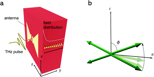
We theoretically explore spin-wave propagation in a nonlinear regime, driven by the intense terahertz pulse. In contrast to previous research, we take into account the spatial inhomogeneity of the exciting pulse and consequent propagation of the spin deflection in space. We use the Lagrangian equation of spin dynamics that yields both time evolution and spatial distribution of the magnetization as the solution.19 For an antiferromagnet this equation has the form of a sine-Gordon equation. For the indicative case of orthoferrites, the equation of motion is given by:16 | (1) |
Rare earth orthoferrites exhibit spin-reorientations, so the orientation of the antiferromagnetic vector flips or rotates across a specific temperature point or interval. For instance, part of orthoferrites, such as TmFeO3, ErFeO3 and SmFeO3, have transitions from Γ2 to Γ4 phases as temperature increases.8 The magnetization pointed along the a-axis in the Γ2 phase moves continuously by 90 degrees to the c-axis in the Γ4 phase. We focus on the intermediate Γ24 phase with the antiferromagnetic vector in the ac-plane, in which considerably large nonlinearity was reported.20 At that phase, four equilibrium states, given by local minima of the potential energy, are placed in the ac-plane in the case of the zero bias field (Fig. 1b). The function η(T) in eqn (1) defines the equilibrium orientations and reads
 | (2) |
We consider two processes of excitation via the electric field and magnetic field of the THz pulse separately. The first term of the right-hand side of eqn (1) represents the modulation of magnetocrystalline anisotropy by THz electric field. The high-intensity electric field ETHz distorts the anisotropy mediated by the orbital states of the rare-earth ions and causes the spin excitation indirectly. Other three terms describe Zeeman coupling, which is a direct interaction between the external magnetic field Hext and the net magnetization. Regarding the magnetic field, we assume two origins for Hext in this paper: the static bias field Hbias is independent of time, which alters the potential energy steadily. As a result, the symmetry in the ac-plane is broken; conversely, the dynamic magnetic field HTHz is caused by the pump terahertz pulse. Since the torques exerted by HTHz and ETHz are additive, we compare their effects by solving the equation while only one of these terms is present.
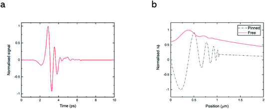
The shape of the terahertz pulse with amplitudes, Hamp and Eamp, was taken from our measured data for the THz fields generated by tilted-pulse-front excitation and detected by electro-optical sampling.6 The manual zero filling to the latter data was implemented to generate the longer time scale (normalised data s(t) shown in Fig. 2). Furthermore, we postulated that the electric field and the magnetic field had exponential distribution with homogeneous offset in the substrate to describe the distribution of the near field in the vicinity of the antenna. The antenna fabricated on the surface enhances the terahertz signal and localizes the intensity at the neighbourhood of the antenna.3 The distribution function is formulated as:
 | (3) |
 | (4) |
Results and discussion
Numerical modelling
We adopted a solving method called the Finite Difference Method to analyse the equation numerically. The boundary condition was mainly designated as the Neumann (free boundary) condition, given by ∂ϕ/∂y(y = 0) = 0, to consider the switching phenomena. We applied all parameters for compound TmFeO3, featured in recent experiments on THz spin control.16,20 The effective fields of exchange interactions were taken from,21Hd = 2 × 10⁵ Oe and He = 2 × 10⁷ Oe. The set of transition temperatures of this material is known as approximately Tu = 90 K and Tl = 80 K. The value ωa = 2.1 rad ns−1, ξ = 2.3 × 10¹⁸ erg−1 cm3 s−1 and α = 1.4 × 10⁻⁴ was experimentally determined from the data of the quasi-ferromagnetic resonance frequency at T = 83 K.3 Although those two parameters depend on frequency in a strict sense, we regarded them as constants to simplify the calculation. Besides, Cm = 2 × 106 cm s−1 was used.5In our calculations, the temperature was fixed at the midpoint within the spin reorientation temperature interval, namely T = 85 K. One of the equilibrium angles ϕ0 in the case of the no bias field was accurately set to 45° and the others are located in the fourth-fold symmetric positions. However, the bias field slightly shifts the stationary point of the potential. This means that initial values ϕ(t = 0) close to ϕ = 45 deg should be compensated adequately to remove the excitation by the bias field. After recalculation of the potential to know the new local minima with bias magnetic field, we applied initial conditions, ϕ(t = 0) = ϕ0 and ∂ϕ/∂t(t = 0) = 0 and they are spatially uniform. For parameters for the field distribution, we used A = 8 and d = 4 μm, which were the values used to model the antenna response in the previous experiment.15
Results
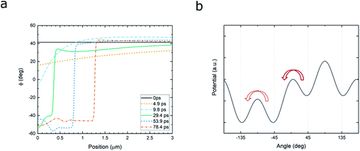
At first, we calculated the spin dynamics in a linear regime with a small THz amplitude, to clarify the linear background to the nonlinearity. For the Neumann condition, the THz field HTHz = 45 kOe and the bias field Hbias = 2 kOe along the x-axis were applied. In addition, we took the Dirichlet (pinned boundary) condition, expressed as ϕ(y = 0) = 0, with different amplitude HTHz = 900 Oe. The pinned condition can be accepted easily for the weak excitation regime, while the pinning on edges should be an unrealistic condition for strong driving and subsequent nonlinear switching phenomena. The result for both cases is illustrated in Fig. 2b. The uniform spin precession, zero-wavenumber spin wave shaped by the antenna was dominant, especially in the Neumann case. Also, the spin wave whose wavenumber was finite, not zero, propagated in spite of the much smaller amplitude than the uniform mode. These results were comparable to a previous simulation on linear propagation excited by an optical pump.17Next, increasing the intensity of THz field, we stepped into the nonlinear regime. The enhanced magnetic field, HTHz = 54 kOe, induced nonlinear dynamics, involving flipping of the antiferromagnetic vector into another equilibrium orientation (Fig. 3a, see also ESI Movie 1†). This creates a non-stationary domain wall separating the regions with metastable spin orientations. The external bias Hbias = 2 kOe along the x-axis eliminated the two local minima around ϕ = ±135° (Fig. 3b). In the first part of the process in about ten picoseconds, the spin around the antenna moves to the other equilibrium position. This phenomenon is caused by inertia motion following the main peak of the THz pulse (at t < 3 ps in Fig. 2a). On the other hand, the angle of spins at a distant position from the antenna return to the initial position as a result of damping. This localised reversal forms a domain wall between the different spin orientations around y = 0.3 μm, and the position of the wall after the THz pulse duration is fixed all the time. The position of the domain wall is determined by the parameter d in eqn (3), the penetration depth of the THz field for the chosen wave form and spatial distribution. This position corresponds to the threshold THz amplitude, required to bring the magnetic order parameter over the potential barrier separating two equilibrium orientations (see Fig. 3b). At the same time the sudden appearance of this discontinuity generates spin waves with finite wavenumbers propagating into both positive and negative directions from the domain wall. The spin wave emission mechanisms resemble the linear regime mentioned before (Fig. 2b). The domain wall plays the role of the pinned boundary.
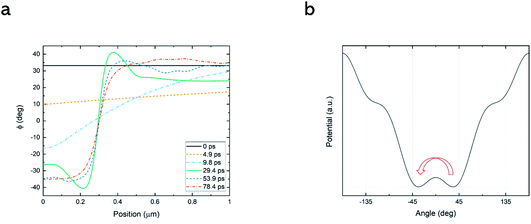
The different orientation of the bias field along the z-axis provide completely different results, accompanied with movement of the domain wall (Fig. 4a, ESI Movie 2†). The comparably weak bias Hbias = 500 Oe along the z-axis reduced the barrier to facilitate the switching by the THz pulse with the amplitude, HTHz = 54 kOe. The long-distance propagation of the wall follows from the different potential landscape (Fig. 4b). The bias modulated the symmetric potential to non-symmetric one at about ϕ = 0 and pushed up the initial position ϕ0 to the metastable state. The spin on this local minimum state fell down to the lower global minimum around ϕ = −45°. This is the origin of the domain movement. Moreover, the larger amplitude of bias field, for example Hbias = 1 kOe, caused the other domain wall between ϕ = −45° and ϕ = −135°, which stayed at the same position (see ESI Movie 3†). The boundary was essentially the same as the result shown in Fig. 3a from the standpoint of the equal potential levels.
 | ||
| Fig. 4 (a) Snapshots of the spin deflection angle in the strongly nonlinear regime, when the bias magnetic field is applied along the z-axis and the spins are initially aligned in a metastable state. In contrast to the situation shown in Fig. 3, here the domain wall is moving away from the sample boundary. (b) The potential landscape with the bias oriented z-axis show that the main excitation occurred as a result of falling through the slope between −45° and 45°. | ||
To compare dynamics induced by the electric field to one by the magnetic field, we applied ETHz = 9 MV cm−1 to eqn (1) and neglected terms for the Zeeman effect. We calculated only one case with Hbias = 2 kOe along the x-axis. The obtained result was quite similar (ESI Movie 4†) to the one shown in Fig. 3a because the action of ETHz can be seen as an effective magnetic field pulse.
Conclusions
In summary, we developed the model for nonlinear and non-local spin dynamics relevant to the recent experiments with THz pump pulses concentrated by the metallic antennas fabricated on top of the antiferromagnetic sample. We predict the formation of the non-stationary and at certain conditions a moving boundary, separating stable orientations of the antiferromagnetic vector. The resulting moving discontinuity can emit spin waves. The propagation of waves through the moving boundary opens a new vistas for the non-stationary effects such as modulation of the spin wave frequencies reminiscent of propagation of the electro-magnetic waves across the relativistic boundary. We believe our theoretical results will inform and inspire future experimental work in the burgeoning field of antiferromagnetic magnonics.Author contributions
Y. S. has performed the mathematical derivation and numerical calculations and analysis under the guidance of R. V. M., who formulated the project and supervised it.Conflicts of interest
There are no conflicts to declare.Acknowledgements
This work was funded by the European Research Council ERC grant agreement no. 852050 (MAGSHAKE).References
- T. Jungwirth, X. Marti, P. Wadley and J. Wunderlich, Nat. Nanotechnol., 2016, 11, 231–241 CrossRef CAS PubMed.
- P. Němec, M. Fiebig, T. Kampfrath and A. V. Kimel, Nat. Phys., 2018, 14, 229–241 Search PubMed.
- V. V. Eremenko, N. F. Kharchenko, Y. G. Litvinenko and V. M. Naumenko, Magneto-Optics and Spectroscopy of Antiferromagnets, Springer, 1992 Search PubMed.
- A. V. Kimel, A. Kirilyuk, P. A. Usachev, R. V. Pisarev, A. M. Balbashov and T. Rasing, Nature, 2005, 435, 655–657 CrossRef CAS PubMed.
- J. Hebling, G. Almasi, I. Kozma and J. Kuhl, Opt. Express, 2002, 10, 1161 CrossRef CAS PubMed.
- T. Kampfrath, A. Sell, G. Klatt, A. Pashkin, S. Mährlein, T. Dekorsy, M. Wolf, M. Fiebig, A. Leitenstorfer and R. Huber, Nat. Photonics, 2011, 5, 31–34 CrossRef CAS.
- T. Suemoto, K. Nakamura, T. Kurihara and H. Watanabe, Appl. Phys. Lett., 2015, 107, 042404 CrossRef.
- A. M. Kalashnikova, A. V. Kimel, R. V. Pisarev, V. N. Gridnev, P. A. Usachev, A. Kirilyuk and T. Rasing, Phys. Rev. B: Condens. Matter Mater. Phys., 2008, 78, 104301 CrossRef.
- T. Satoh, S.-J. Cho, R. Iida, T. Shimura, K. Kuroda, H. Ueda, Y. Ueda, B. A. Ivanov, F. Nori and M. Fiebig, Phys. Rev. Lett., 2010, 105, 077402 CrossRef PubMed.
- A. V. Kimel, A. Kirilyuk, A. Tsvetkov, R. V. Pisarev and T. Rasing, Nature, 2004, 429, 850–853 CrossRef CAS PubMed.
- A. V. Kimel, B. A. Ivanov, R. V. Pisarev, P. A. Usachev, A. Kirilyuk and T. Rasing, Nat. Phys., 2009, 5, 727–731 Search PubMed.
- T. Li, A. Patz and L. Mouchliadis, et al., Femtosecond switching of magnetism via strongly correlated spin–charge quantum excitations, Nature, 2013, 496, 69–73 CrossRef CAS PubMed.
- D. Afanasiev, B. A. Ivanov, A. Kirilyuk, T. Rasing, R. V. Pisarev and A. V. Kimel, Phys. Rev. Lett., 2016, 116, 097401 CrossRef CAS PubMed.
- J. A. de Jong, I. Razdolski, A. M. Kalashnikova, R. V. Pisarev, A. M. Balbashov, A. Kirilyuk, T. Rasing and A. V. Kimel, Phys. Rev. Lett., 2012, 108, 157601 CrossRef CAS PubMed.
- Y. Mukai, H. Hirori, T. Yamamoto, H. Kageyama and K. Tanaka, New J. Phys., 2016, 18, 013045 CrossRef.
- S. Schlauderer, C. Lange, S. Baierl, T. Ebnet, C. P. Schmid, D. C. Valovcin, A. K. Zvezdin, A. V. Kimel, R. V. Mikhaylovskiy and R. Huber, Nature, 2019, 569, 383–387 CrossRef CAS PubMed.
- T. Kurihara, H. Watanabe, M. Nakajima, S. Karube, K. Oto, Y. Otani and T. Suemoto, Phys. Rev. Lett., 2018, 120, 107202 CrossRef CAS PubMed.
- J. R. Hortensius, D. Afanasiev, M. Matthiesen, R. Leenders, R. Citro, A. V. Kimel, R. V. Mikhaylovskiy, B. A. Ivanov and A. D. Caviglia, Nat. Phys., 2021, 17, 1001–1006 Search PubMed.
- A. K. Zvezdin, Pis’ma Zh. Eksp. Teor. Fiz., 1979, 10, 605 Search PubMed.
- S. Baierl, M. Hohenleutner and T. Kampfrath, et al. , Nat. Photonics, 2016, 10, 715–718 CrossRef CAS.
- A. M. Balbashov, G. V. Kozlov, A. A. Mukhin and A. S. Prokhorov, in High Frequency Processes in Magnetic Materials, World Scientific, 1995, pp. 56–98 Search PubMed.
Footnote |
| † Electronic supplementary information (ESI) available. See https://doi.org/10.1039/d2fd00035k |
| This journal is © The Royal Society of Chemistry 2022 |


