 Open Access Article
Creative Commons Attribution 3.0 Unported Licence
Bridging electrocatalyst and cocatalyst studies for solar hydrogen production via water splitting
Masaki
Saruyama
 *,
Christian Mark
Pelicano
 and
Toshiharu
Teranishi
 *
*
Institute for Chemical Research, Kyoto University, Gokasho, Uji, Kyoto 611-0011, Japan. E-mail: saruyama@scl.kyoto-u.ac.jp; teranisi@scl.kyoto-u.ac.jp
First published on 8th February 2022
Abstract
Solar-driven water-splitting has been considered as a promising technology for large-scale generation of sustainable energy for succeeding generations. Recent intensive efforts have led to the discovery of advanced multi-element-compound water-splitting electrocatalysts with very small overpotentials in anticipation of their application to solar cell-assisted water electrolysis. Although photocatalytic and photoelectrochemical water-splitting systems are more attractive approaches for scaling up without much technical complexity and high investment costs, improving their efficiencies remains a huge challenge. Hybridizing photocatalysts or photoelectrodes with cocatalysts has been an effective scheme to enhance their overall solar energy conversion efficiencies. However, direct integration of highly-active electrocatalysts as cocatalysts introduces critical factors that require careful consideration. These additional requirements limit the design principle for cocatalysts compared with electrocatalysts, decelerating development of cocatalyst materials. This perspective first summarizes the recent advances in electrocatalyst materials and the effective strategies to assemble cocatalyst/photoactive semiconductor composites, and further discusses the core principles and tools that hold the key in designing advanced cocatalysts and generating a deeper understanding on how to further push the limits of water-splitting efficiency.
1. Introduction
Reducing the amount of CO2 emitted from burning fossil fuels is essential to mitigate global warming.1 To meet this challenge while addressing the growing global energy demand, it is becoming increasingly important to develop sustainable, carbon-neutral energy sources.2 Molecular hydrogen (H2) is regarded as an ideal green fuel because it releases zero emissions and only produces water upon combustion.3 Therefore, H2 is expected to hold prime significance as a high-energy-density fuel in future energy systems. In fact, H2 fuel cells have been implemented to power vehicles with advanced H2 transportation technologies.4Although hydrogen is the most abundant element on earth, the dihydrogen molecule rarely exists in nature; therefore, H2 must be produced artificially. Currently, steam reforming is the preferable method for producing commercial H2; however, a substantial amount of energy is required to drive this process and CO2 is emitted as a byproduct.5 Recently, sunlight-driven water splitting has emerged as an attractive approach for green and sustainable H2 production.6 Among solar-hydrogen technologies, water electrolysis using electricity generated from solar cells is considered to be the most advanced pathway.7 Combining a solar cell with an electrocatalyst (EC)-loaded electrode can promote water splitting, reaching >30% solar-to-hydrogen efficiency (STH) using an InGaP/GaAs/GaInNAsSb triple-junction solar cell.8
Thermodynamically, the reduction and oxidation of water start at 0 VRHE and +1.23 VRHE, respectively, meaning that the overall water-splitting reaction can start from 1.23 V. However, the activation energy for each half-reaction contributes to an overpotential, which requires an additional voltage (hundreds of millivolts) to overcome and drive the water-splitting process.9 In practical applications, ECs are employed to reduce this overpotential, thereby improving the STH.
To date, the high cost of device manufacturing has hindered the practical implementation of solar cell-assisted H2-production devices. However, the direct decomposition of water through photocatalysis represents a promising alternative approach owing to its technical simplicity and low associated investment costs.10,11 Scaling up a photocatalytic system is also relatively much easier because water splitting can proceed by simply immersing semiconductor photocatalyst (PC) powder in water under light irradiation.12 Recently, a large-scale experiment (100 m2 scale) demonstrated that immobilizing powdered PCs on panels could lead to the production of about 600 L of H2 on a sunny day.13 Such photoactive semiconductors can also be used as light-absorbing layer of photoelectrodes (PEs) for photoelectrochemical (PEC) water-splitting cells.14 These electrodes are usually placed in separate compartments which are electrically connected through an external circuit. Although this configuration makes PEC systems more complex in terms of design, higher STH efficiencies have been achieved due to easier product collection and elimination of potential back-reactions.15 For example, a tandem-type PEC cell reached an STH of >7%, which far exceeds current STH values for PC systems.16 However, both PC and PEC systems still have large rooms to reach a target STH of 10% with a long-term durability for practical application.12
To realize a higher water-splitting performance, substantial efforts have been mainly devoted to the development of semiconductors as efficient photoactive materials.10 Cocatalysts (CCs), which are water-splitting catalysts coupled with PCs or PEs, also have been systematically studied as equally-important components in both PC and PEC systems.17 Because the semiconductor surface tends to have a weak driving force for redox reactions involving water, coupling with CCs can facilitate these redox reactions by lowering the activation energy barrier.17 Specifically, charged-up CCs retain suitable steady-state potentials to drive the surface reactions by serving as trapping sites for photogenerated carriers (i.e., electrons and holes). In turn, this process not only promotes charge separation but also suppresses adverse charge recombination and photocorrosion.18,19
While the integration of CCs with PCs and PEs is indispensable for achieving excellent efficiencies, the CC materials have been explored much less than the EC materials. The straightforward application of previously-reported ECs materials as CCs is challenging because it introduces various factors that must each be critically considered.18 First, CCs should be small or thin enough so that they do not limit the amount of light absorbed by the PC and PE.20 Second, the change in potential shift at the CC/semiconductor junction is critical for evaluating charge transfer efficiency.21 These additional requirements have not yet been sufficiently addressed, delaying advancement related to CC materials.
In this perspective, we discuss the recent advances in the design of EC materials and the strategies for constructing CC/PC and CC/PE composites, including our group's nanoparticle (NP)-adsorption approach. A special emphasis is put on the key principles governing the rational assembly of an efficient CC/PC and CC/PE system. We hope this perspective will inspire researchers in pursuit of bridging the gap between the developments of highly-active EC and CC materials, which have only been studied separately to date (Fig. 1).
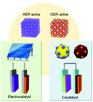 | ||
| Fig. 1 Application of materials active for solar-driven water splitting via the hydrogen evolution reaction (HER) and oxygen evolution reaction (OER). | ||
2. Electrocatalysts for water electrolysis
2.1 Development of electrocatalyst materials
Water splitting involves two concurrent catalytic half-reactions: the hydrogen evolution reaction (HER) and the oxygen evolution reaction (OER). Materials that can lower the activation energies of these reactions are utilized as ECs. Although noble metals such as Pt, Ru(Ox) and Ir(Ox) are still representative efficient ECs for water splitting, diverse earth-abundant compounds with comparable catalytic activities have also been developed based on comprehensive theoretical and experimental studies.22 Herein, we briefly introduce recently-developed EC materials for efficient water splitting and discuss their typical preparation methods. A comprehensive introduction of EC materials is beyond the scope of this perspective; thus, we encourage the interested reader to refer to recent reviews summarizing the development of EC materials.23,24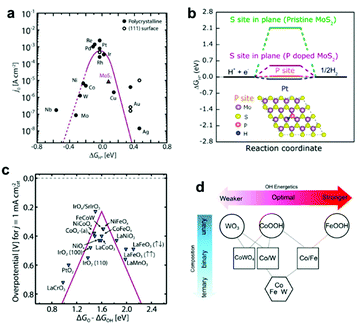 | ||
| Fig. 2 (a) Volcano plot relating the ECs' HER activities and ΔGH*; (b) HER free–energy diagram for P and S sites in the basal plane of pristine and P-doped MoS2; (c) OER volcano plot for metal oxides; (d) OH adsorption energetics (ΔGOH*) as a function of the material's composition obtained by interpolation between the calculated pure phases of WO3 (001), CoOOH (01−12), FeOOH (010), and CoWO4 (010) planes. Adapted with permission from (a and c) ref. 22, (b) ref. 27, and (d) ref. 44; copyright 2017 American Association for the Advancement of Science (AAAS), 2017 the American Chemical Society (ACS), and 2016 AAAS, respectively. | ||
| EC | Preparation method | Catalysis | Overpotential (mV for 10 mA cm−2) | Electrolyte | Ref. |
|---|---|---|---|---|---|
| a OWS = overall water splitting. | |||||
| P-doped MoS2 | Hydrothermal | HER | 43 | 0.5 M H2SO4 | 27 |
| Re1–xMoxSe2 | Hydrothermal | HER | 77 | 0.5 M H2SO4 | 34 |
| Fe0.5Co0.5P | Hydrothermal + phosphidation | HER | 37 | 0.5 M H2SO4 | 33 |
| 20w% Pt/C | Commercial | HER | 27 | 0.5 M H2SO4 | 34 |
| Fe3GeTe2 | Solid-state reaction | HER | 105 | 1 M KOH | 35 |
| Ni2Mo3N | Nitridation | HER | 21.3 | 1 M KOH | 36 |
| Ni6Mo6C/NiMoOx | Hydrothermal + carburization | HER | 29 | 1 M KOH | 37 |
| 20w% Pt/C | Commercial | HER | 32 | 1 M KOH | 37 |
| G-FeCoW | Sol–gel | OER | 191 | 1 M KOH | 44 |
| NiCoFe–P–NP@NiCoFe–PBA | Precipitation + phosphidation | OER | 223 | 1 M KOH | 49 |
| (CrMnFeCoNi)Sx | Pulse thermal decomposition | OER | 116 | 1 M KOH | 51 |
| CoVFeN | Hydrothermal + electrodeposition + nitridation | OER | 212 | 1 M KOH | 53 |
| Mo6Ni6C | Hydrothermal + carburization | OER | 190 | 1 M KOH | 54 |
| RuO2 | Commercial | OER | 264 | 1 M KOH | 49 |
| IrO2 | Commercial | OER | 290 | 1 M KOH | 54 |
| NiFe LDH | Electrodeposition | OER | 250–300 | 1 M KOH | 52 |
| RuIr | Chemical reduction | OWS | 255 | 0.05 M H2SO4 | 56 |
| SrNb0.1Co0.7Fe0.2O3−δ | Solid-state reaction | OWS | 450 | 1 M KOH | 55 |
| MoS2/Ni3S2 | Solvothermal | OWS | 330 | 1 M KOH | 57 |
| NiMoP NSs@MCNTs | Hydrothermal | OWS | 369 | 1 M KOH | 58 |
| Ni–Fe–MoN | Solid-state reaction | OWS | 228 | 1 M KOH | 59 |
2.2 Synthesis and use of electrocatalysts
To date, innovative EC materials have been synthesized through various chemical and physical routes. Because the overall size of the ECs does not require fine-tuning (as long as they are conductive enough to work on electrodes), they have mainly been fabricated using facile strategies, including solvothermal syntheses, solid-state reactions, and electrochemical deposition (Fig. 3a). This enables rapid and widespread exploration of novel EC materials via screening experiments.62 Simple oxides and chalcogenides can be directly synthesized by liquid-phase methods under mild conditions,62,63 whereas high-temperature annealing is often required to obtain phosphides, nitrides, and carbides from their corresponding preformed oxides.34–36,51,52 Specifically, they are annealed with precursors (P = NaH2PO2; N = NH3; C = organic molecule) in a furnace at >300 °C for complete conversion. To assess the resulting material's electrocatalytic activity, powdered ECs are embedded on a conductive carbon substrate, and the composite is typically glued to an electrode surface using a Nafion binder.64 ECs can also be grown directly on porous conductive supports, such as metal foam or carbon paper/cloth, which increase their conductivity and loading per geometrical unit area (Fig. 3c and d).37,38,65 Such EC-grown substrates can be directly connected to a potentiostat as free-standing electrodes. Alternatively, nanosizing is a practical approach for designing active ECs with large surface areas because it provides unsaturated surface atoms and promotes greater atomic usage efficiency.23 Effective techniques for fabricating EC nanoparticles (NPs) include colloidal synthesis and precursor decomposition on a support material.51,66 Annealing a metal–organic framework (MOF) is a facile technique to produce multi-metallic NPs supported on a porous conductive carbonaceous substrate (Fig. 3b).49 Moreover, recent advances have revealed that single-atom (SA) catalysts are emerging as new ECs with exceptional properties, such as maximum atomic usage efficiency, high activity of the metal complex, and high durability of the bulk catalyst.67 Similar to powdered ECs, EC NPs and SA catalysts can be supported on conductive substrates and fixed to an electrode. These EC electrodes operate as working electrodes in a three (working, reference, and counter)-electrode system to evaluate their catalytic performance towards HER and/or OER.68 Overall water splitting is investigated in a two (working + counter)-electrode configuration using two identical EC-immobilized electrodes (Fig. 3h).55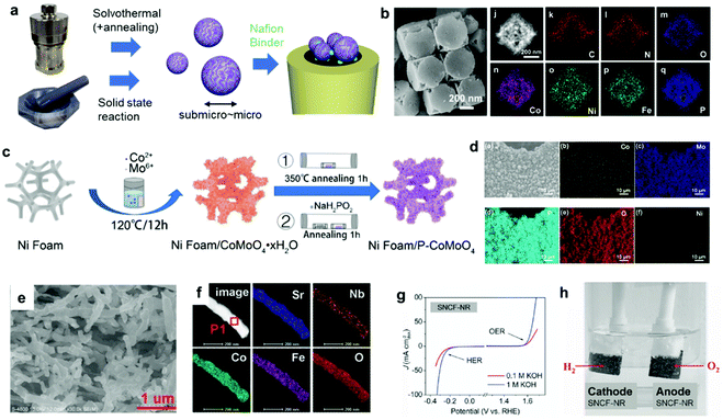 | ||
| Fig. 3 (a) Typical synthetic strategies for powdered ECs and the corresponding electrode preparation; (b) MOF-derived NiCoFe–P NPs containing porous nanocages; (c) direct EC (P–CoMoO4) growth on a Ni foam electrode through a solvothermal method and phosphidation via annealing; (d) elemental mapping of a Ni foam/P–CoMoO4 composite electrode; (e) scanning electron microscopy (SEM) and (f) elemental mapping images, (g) CV, and (h) overall water-splitting experiment using a bifunctional SrNb0.1Co0.7Fe0.2O3−δ EC. Adapted with permission from (b) ref. 49, (c and d) ref. 38, and (e–h) ref. 55; copyright 2021 ACS, 2020 Wiley, and 2017 Wiley, respectively. | ||
It is worth noting that ECs can undergo some changes during catalysis, especially in a OER environment.69 According to the Pourbaix diagram, the surface or entire EC can transform into its corresponding [(oxy)hydr]oxide under alkaline conditions under a positive applied potential (Fig. 4a–e).70 Wu et al. reported that the surface of Co4N was progressively oxidized during OER cyclic voltammetry (CV) experiments in 1 M KOH electrolyte.71 Even if the composition is carefully controlled during synthesis, the real active species may deviate from the as-prepared material. Such transformed oxides and (oxy)hydroxides frequently exhibit superior catalytic activities because their amorphous surfaces offer more active sites and enhanced electronic interactions relative to their pure oxide analogs (Fig. 4f and g).72 In calculations of the surface state, a lack of understanding of the real active species may mislead research conclusions.
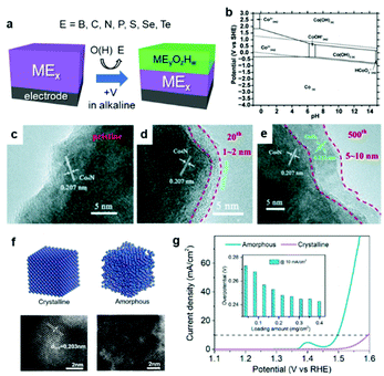 | ||
| Fig. 4 (a) Schematic diagram illustrating the in situ oxidation of an EC; (b) Pourbaix diagram of Co–H2O system; (c–e) transmission electron microscope (TEM) images of the Co4N EC surface before and after 20 and 500 cycles of CV for OER; (f) structural differences between crystalline and amorphous NiFe and (g) their corresponding OER polarization curves. Adapted with permission from (b) ref. 70, (c–e) ref. 71, and (f and g) ref. 72; copyright 2019 the Royal Society of Chemistry (RSC), 2015 Wiley, and 2020 ACS, respectively. | ||
3. Cocatalysts for PC and PEC systems
In the case of solar cell-assisted water splitting, EC-loaded electrodes can be employed in the same configuration as two electrode system. Therefore, improving intrinsic catalytic activity of EC directly increases the STH, aside from the solar cell efficiency. In terms of PC and PEC systems, the latest advancements in semiconductor design (e.g., defect engineering and morphology control) have paved the way for advanced PCs and PEs with high light-energy conversion efficiencies.73 Nevertheless, additional considerations concerning the successful integration of efficient EC materials as CCs onto the PC and PEC systems must be addressed. First, it is essential for the CCs to have suitable NP dimensions and homogenous distribution on the PC and PE to ensure that they do not block the incident light. Second, designing an optimal interface between the semiconductor and CC is necessary because the stability and performance of the entire system largely depend on this junction. Such requirements significantly limit the range of material dimensions (e.g. size, shape, and light absorbance.) that can be viewed as valuable for CCs, thereby hindering further development of CC research compared with EC research.Despite these difficulties, a significant amount of effort has been dedicated to the hybridization of water-splitting catalyst materials with semiconductors to realize high-performance photocatalytic and PEC systems.74 Unlike in the synthesis of ECs, the stability of PCs and PEs must be considered when constructing CC/semiconductor composites. PCs based on (oxy)nitride and (oxy)chalcogenide decompose easier than pure oxides, while other PCs become inactive because of a change in the metal valence.75 As introduced in Section 2, some methods for efficient EC formation require high-temperature annealing, and such a harsh condition cannot be applied to unstable semiconductors. In this section, we summarize representative strategies for loading CCs onto PCs and PEs (Fig. 5a, Tables 2 and 3).
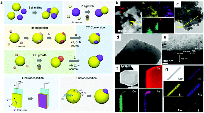 | ||
| Fig. 5 (a) Representative strategies for assembling CC/PC composites; (b) VN loaded on CdS via ball-milling; (c) CdS grown on BP via a hydrothermal method; (d) Ca2FeCoO5 loaded on TiO2via impregnation; (e) NiCo2O4 grown on a TiO2/BiVO4 photoelectrode via a hydrothermal method; (f) CoOx-FeOx coated on Ta3N5:Mg + Zr via electrodeposition; (g) MoS2 and CoPi loaded on CdS nanowires via photodeposition. Adapted with permission from (b) ref. 80, (c) ref. 87, (d) ref. 101, (e) ref. 127, (f) ref. 134, and (e) ref. 122; copyright 2019 ACS, 2020 ACS, 2020 Wiley, 2020 ACS, 2015 ACS, and 2019 ACS, respectively. | ||
| CC | Loading method | AQY (% @ 420 nm) | Sacrificial reagent | Ref. |
|---|---|---|---|---|
| VN | Sonication | 5.3 | Lactic acid | 80 |
| P-doped Ni2S | Sonication | 4.8 | Na2S + Na2SO3 | 81 |
| WP | Ball-milling | 10.5 | (NH4)2SO3 | 82 |
| Co3C | Mixing + annealing | 17 | Na2SO3 + Na2S | 86 |
| FeSe | Sonication + annealing | 6.71 | Na2S + Na2SO3 | 85 |
| MoS2/C | PC growth | 28.1 | Lactic acid | 91 |
| Co3S4/Co@C | PC growth | ∼15 | Na2S + Na2SO3 | 92 |
| Ni3S2 | PC growth | 7.86 | Lactic acid | 93 |
| Mo2N | PC growth | 2.2 | Na2S + Na2SO3 | 94 |
| WS2 | Impregnation | 5.0 | Lactic acid | 98 |
| CoO | Impregnation | 40.64 | Lactic acid | 99 |
| NiS | Hydrothermal | 74.1 | Lactic acid | 106 |
| MoS2 | Hydrothermal | 41.37 | Lactic acid | 107 |
| NiCoP/NiCoPi | Hydrothermal + phosphidation | 45 | Lactic acid | 111 |
| β-Ni(OH)2 | Photodeposition | 72 | Ethanol | 116 |
| WSx | Photodeposition | 14.7 | Lactic acid | 120 |
| CoPi | Photodeposition | 24.3 | Lactic acid | 121 |
| MoS2-CoPi | Photodeposition | 36 | Lactic acid | 122 |
| Semiconductor | CC | CC loading method | Photocurrent density (mA cm−2 @ 1.23 V) | Ref. |
|---|---|---|---|---|
| BiVO4 | FeSnOS | Impregnation | 3.1 | 124 |
| BiVO4/TiO2 | NiCo2O4 | Hydrothermal | 2.47 | 127 |
| BiVO4 | NiFeY LDH | Hydrothermal | 5.2 | 128 |
| BiVO4 | F:Co(CO3)xOHy | Hydrothermal | 5.5 | 129 |
| BiVO4 | Co–LaFeO3 | Electrodeposition | 3.4 | 135 |
| BiVO4 | FeOOH/NiOOH | Light-assisted electrodeposition | 4.2 | 136 |
| BiVO4 | NiPx@FePyOz | NP adsorption | 2.3 | 148 |
| BiVO4 | CuCoO2 | NP adsorption + annealing | 3.32 | 126 |
| Ta3N5 | FeNiOx | Impregnation | 9.95 | 125 |
| Ta3N5 | FeNiCo | Electrodeposition | 4.0 | 133 |
| Ta3N5 | Co–Pi/Co(OH)x/NiFe-LDH | Adsorption + electrodeposition + solvothermal | 6.3 | 137 |
| Ta3N5 | Ni:CoFeOx | Light-assisted electrodeposition | 5.3 | 138 |
3.1 Cocatalysts loading on powdery photocatalysts
In photocatalysis using powdery PCs, both reduction and oxidation reactions take place on an individual PC particle, requiring two suitable surfaces on an PC particle to drive each particular half-reaction. Generally, CCs for a specific half-reaction are first loaded onto the PC surface leaving the other regions available to facilitate the other half-reaction, which is especially advantageous for examining individual half-reactions including the cases using sacrificial reagents. For overall water-splitting PC, the loading of CCs for both HER and OER can further accelerate the total reaction to attain higher photocatalytic performance.76Chemical methods are also applicable to hybridize PC with synthetic CC materials. Adding a CC to a PC synthetic system can grow typical PCs, such as CdS, on the CC surface under mild hydrothermal conditions (Fig. 5c).87–94 However, this technique is not viable for bulk oxide-based PCs (e.g., SrTiO3) which require high-temperature (>800 °C) solid-state synthetic reactions that can lead to CC decomposition.
As mentioned in Section 2, a gas phase reaction can be employed to modify the composition of preformed oxide CCs. To promote the formation of high-quality chalcogenide, phosphide, nitride, and carbide CCs, which hardly form via impregnation or solvothermal methods, supplemental annealing treatments must be implemented. As a result, stable PCs with excellent thermal resistance (e.g., C3N4) are mostly used for this approach.108–111
In order to shed some light on the dependence of photocatalytic performance on the type of CC-loading method, apparent quantum yield (AQY) values (at 420 nm) for well-studied CdS/CC composites in the presence of hole scavengers are listed in Table 2. Although fair comparison between works under different conditions is difficult, rough tendency of AQY depending on loading method can be seen. CdS PCs loaded with CCs through physical mixing tend to show relatively lower AQY of around 10%. Meanwhile, CdS/CC composites assembled using hydrothermal and photodeposition methods can reach much higher AQY of up to ∼70%. These results suggest that the creation of an atomic-level PC/CC interface is paramount for a smooth carrier migration and reduced bulk recombination of photogenerated charge carriers in PCs.
3.2 Cocatalysts loading on photoelectrodes
In PEC systems, the photogenerated minority carriers diffuse to the semiconductor surface and the majority carriers are collected by the conductive substrate. For example, in photoanode containing n-type semiconductor, the electrons travel to the counter electrode, and the holes on photoanode surface and the electrons on the counter electrode surface are used to drive oxidation and reduction half-reactions, respectively. Therefore, unlike powdery PC systems, only one half-reaction (oxidation on n-type and reduction on p-type semiconductor) takes place on the PE surface, which requires the loading of appropriate CCs for each reaction.Accordingly, efficient collection of majority carriers (holes in p-type and electrons in n-type semiconductors) requires a small resistance at the semiconductor/electrode interface and within the grain boundaries of semiconductor layer.123 Hence, CCs are typically loaded after fabricating high-quality PEs, wherein a mild CC-loading condition is necessary not to damage those prebuilt PEs. Impregnation by drop casting the CC precursor and a subsequent mild annealing is often applied when constructing CC/PE composites.124–126 Hydrothermal method can also be employed by immersing PEs in a reaction vessel containing CC precursors (Fig. 5e).127–129 These methods enable the formation of multi-metallic oxide CC layer on relatively unstable semiconductors like Ta3N5 (Table 3).130
An effective technique to homogeneously coat a CC layer on PEs is an electrodeposition. By applying a potential using a potentiostat, CCs can be deposited as reduced or oxidized species on the PE surface. Light-irradiation is sometimes applied during electrodeposition to assist adequate CC-loading under small applied potential. A representative example of an electrodeposited CC is a CoPi thin film, which is formed by oxidizing a Co precursor with a phosphate electrolyte.131 In addition, FeOOH, NiOOH, and CoOOH are popular OER CCs that can be anodically deposited in a similar way.132–138 These catalysts, coated as homogeneous thin films or NPs, have low absorption coefficients, which is a desirable feature for a CC. Considering that electrodeposition can be carried out at room temperature (RT), both robust BiVO4 and fragile Ta3N5 PCs can be used in this method (Fig. 5f).
3.3 Nanoparticle-adsorption approach
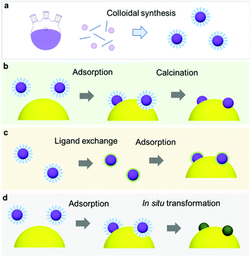
\Recent milestones in colloidal synthesis allow for the preparation of advanced NPs with controlled size and composition.139 Colloidal NPs represent ideal CC candidates because they can offer numerous active sites and enable uninterrupted light absorption by the semiconductor. Selective binding of organic ligands on the NP surface grants the opportunity to precisely engineer their surface.140 Specifically, organic molecules, which have polar functional groups at both ends, can link the NP and semiconductor through hydrogen bonding between the functional groups and OH units on the PC surface (Fig. 7a). However, such ligands behave as an insulating, carrier-blocking layer at the CC/semiconductor interface, and therefore, they should be eliminated (Fig. 6). The standard approach to remove these protective ligands and activate the NP catalysts involves applying an annealing treatment. Previous reports have shown that the required annealing temperature for complete ligand removal changes depending on the type of ligand and the PC support. Our group successfully deposited monodisperse Rh NPs as HER CCs on a GaN:ZnO PC.141–145 Specifically, ultrasmall polyvinylpyrrolidone (PVP) coated-Rh NPs were first adsorbed onto the PC using a linker molecule and then annealed in air at 400 °C (Fig. 7a). Interestingly, the size of the NPs remained ∼1 nm without aggregation after annealing. Negishi et al. also verified the crucial role of annealing to eliminate the ligands on Au clusters without changing their size.146 Such ultrafine NP deposition can only be realized through an NP-adsorption strategy. Depositing ultrasmall CCs can drastically enhance the photocatalytic performance of the composite because the NPs introduce a larger surface area and a greater number of active sites.141 However, larger NPs could reduce the number of cocatalytic sites at the same degree of loading, and this might shield the incident light needed for carrier generation. In this context, fine-tuning the NPs can contribute to a deeper fundamental understanding of the CC effect (e.g., size and structure effects) on photocatalysis (Fig. 7b).144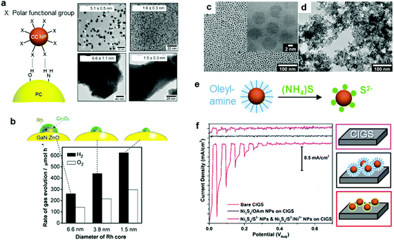 | ||
| Fig. 7 (a) Hydrogen-bonding mediated NP adsorption on PC and size-controlled PVP-coated Rh NPs (top) and Rh NP-loaded GaN:ZnO after calcination treatment (bottom); (b) photocatalytic activity of Cr2O3 shell-coated Rh NPs/GaN:ZnO; (c) oleylamine coated-Ni3S4 NPs; (d) S2−-stabilized Ni3S4 NPs obtained through (e) ligand exchange; (f) photocurrent scanning of bare, oleylamine coated-Ni3S4, and S2−-stabilized Ni3S4 NP-loaded CdS/Cu(In,Ga)Se2 PEs. Adapted with permission from (a and b) ref. 144, (c–f) ref. 147; copyright 2012 ACS and 2017 Wiley, respectively. | ||
Although a thermal treatment is favourable for ligand removal, elevated temperatures and a harsh environment may cause irreversible damage to the PC, PE and the CC NPs. Alternatively, replacing long-chain ligands with small surface-coordinating molecules is an effective way to increase the interfacial contact between the NPs and semiconductor under mild conditions. For example, our group treated oleylamine (OAm)-capped Ni3S4 NPs with S2− at RT to replace the OAm and yield S2−-stabilized Ni3S4 NPs (Fig. 7c–e),147 which were then directly deposited on a CdS/Cu(In,Ga)Se2 PE through a layer-by-layer assembly process. Remarkably, the PE coated with S2−-Ni3S4 NPs exhibited an increase in cathodic photocurrent compared with the OAm-Ni3S4-NPs spin-coated PE, which highlighted the importance of establishing good contact between the CC and PE (Fig. 7f). Additionally, heating treatment to remove OAm from OAm-Ni3S4 layers at 300 °C resulted in deterioration of CdS/Cu(In,Ga)Se2 PE. These results demonstrate that the chemical ligand-removal process can enable the application of NP CCs to unstable PEs.
By exploiting the transformation phenomenon of ECs during catalysis, we demonstrated that applying potential for OER to a NiPx@FePyOz NP-loaded electrode transformed the NPs into highly OER active NiFeOOH film while simultaneously removing their organic ligands (Fig. 8).148 Notably, the colour of the NPs changed from black (phosphide) to colourless (hydroxide), with enhanced transparency for incident visible light. Such a characteristic transformation is highly advantageous for coupling NPs with PCs and PEs under mild conditions. Evidently, the NiPx@FePyOz NP deposition substantially increased the photocurrent of the BiVO4 PE without any post-treatment (Fig. 8c–g), showing that homogeneous NP dispersion can be used as ready-to-use CC ink.
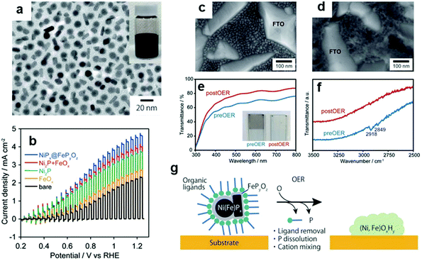 | ||
| Fig. 8 (a) TEM image of NiPx@FePyOz NPs; (b) photocurrent of BiVO4 PEs with/without loading NiPx@FePyOz NPs; SEM images of NiPx@FePyOz (c) before and (d) after CV on a fluorine-doped tin oxide (FTO) electrode; (e) transmittance spectra and (f) Fourier transform infrared (FTIR) spectra that confirm oleylamine ligand removal from NiPx@FePyOz NPs; (g) schematic diagram illustrating the transformation of NPs on BiVO4. Adapted with permission from ref. 148; copyright 2018 RSC. | ||
4. Application of ECs to CCs
As discussed in Section 3, PCs and PEs can be modified with CCs through a variety of strategies to significantly enhance their water-splitting efficiencies. Potential opportunities to further improve the activity could be foreseen if the factors limiting the activity could be identified. For example, what are the core principles relevant for unlocking high-performance CC/PC and CC/PE systems and bypassing rigorous material screening experiments? In this section, we introduce fundamental concepts that play a significant role in designing advanced ECs as CCs for photocatalytic and PEC water splitting.4.1 Energy level matching at the CC/semiconductor interface
When an EC comes in contact with a semiconductor, the band structure of the semiconductor is modulated.149 In general, an electronic contact between a metallic CC and a semiconductor initiates an electron transfer between the semiconductor and the CC until their Fermi levels (EF; the energy level with a 50% probability of electron occupation) equilibrate, which forms a space charge layer. In the space charge layer, the band edge energies of the semiconductor are continuously shifted by the electric field between the semiconductor and the metallic CC. As a result, the energy bands of the semiconductor bend toward the CC. The band bends upward (downward) when the EF of PC is higher (lower) than the EF of CC. Upward band bending creates an energetic upslope (Schottky barrier) for electron transfer but facilitates hole transfer from PC to CC, which encourages photo–oxidation reaction on CCs.149,152 On the contrary, downward band bending promotes electron transfer (ohmic contact) but hinders hole transfer from PC to CC, which is desirable for photo–reduction reaction. Therefore, proper energy level matching to minimize the barrier height or create an ohmic contact for specific carriers is vital for a maximum utilization of photogenerated carriers. Although nanosized CCs have limited capabilities for donating or accepting electrons, loading sufficient amount of CC NPs can still cause band bending in the semiconductor, which has been verified experimentally using Kelvin probe force microscopy and surface photovoltage measurements.150,151 For a CC with semiconductor-like properties, its band alignment with the PC and PE should also be considered to assess the charge transfer efficiency at their interface (Fig. 9b).149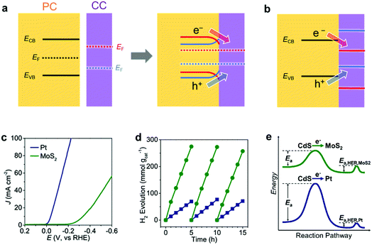 | ||
| Fig. 9 Energy level matching of a PC semiconductor with a CC for (a) metal CC and (b) semiconductor CC [red and blue cases create ohmic contact (Schottky barrier) for photogenerated electrons (holes) and holes (electrons), respectively]; (c) CV comparison of electrochemical HER activity of Pt and MoS2 ECs in 0.5 M H2SO4; (d) photocatalytic HER activity of Pt/CdS and MoS2/CdS composites under visible-light (>400 nm) irradiation; (e) schematic reaction profile showing the activation energy from light absorption to H2 evolution. Adapted with permission from (c–e) ref. 153; copyright 2019 ACS. | ||
Chen et al. clearly demonstrated the beneficial effect of an appropriate CC/PC junction on the photocatalytic activity by loading Pt or MoS2 CCs on the surface of CdS PCs.153 Although Pt has a higher HER activity than MoS2 as an EC (Fig. 9c), the photocatalytic HER activity of the MoS2-loaded CdS was superior to that of the Pt-loaded CdS (Fig. 9d). This observation arose from the differences in their electron transfer rates. Specifically, the deeper EF of Pt caused a greater upward band bending effect in CdS, which simultaneously disturbed the photoexcited electron transfer from CdS to Pt. This suggests that a lower activation potential for electron transfer from CdS makes MoS2 more suitable as a CC than Pt (Fig. 9e). Therefore, the relative performances of ECs do not necessarily reflect their relative applicability as CCs.
To evaluate the carrier transfer efficiency at CC/semiconductor junctions, key parameters (e.g., work function of the metal CC, EF of the semiconductor) deserve deeper investigations. In the case of metals, standard work function data can be used to estimate the bending direction and Schottky barrier height at CC/PC junctions; in contrast, EF and bandgap values for complex heterogeneous CCs are not readily available, which makes evaluations of their band alignment difficult. Nevertheless, DFT and first-principle calculations can provide critical insights on the fundamental electronic structure of EC materials (including band structure, density of states and EF), enabling rapid prediction of suitable PC/CC combinations.
Even if the interfacial band alignments are unknown, the interfacial carrier dynamics can be measured through optical experiments, which can be used to assess the PC/CC interface.154 Transient absorption spectroscopy (TAS) monitors the photogenerated carrier dynamics in a PC by recording the temporal absorption evolution after a pulse excitation.155 For example, TAS reveals (i) how electrons at the conduction band minimum behave in a PC/CC composite after photoexcitation and (ii) the subsequent ultrafast intraband relaxation of hot electrons by probing the absorption in the infrared region derived from free electrons.155,156 Although TAS has been conducted on clear quantum-dot dispersions, TAS measurements for solid-state bulk materials in reflectance mode are still uncommon. Yamakata et al. showed how Pt and CoOx CCs affected the carrier dynamics when deposited on an LaTiO2N PC in the solid state.157 Upon CoOx loading, visible (17![[thin space (1/6-em)]](https://www.rsc.org/images/entities/char_2009.gif) 000 cm−1) and IR (2000 cm−1) probes traced a temporal decrease and increase in the population of holes and free electrons in LaTiO2N, respectively, after a 500 nm laser pulse excitation (Fig. 10). These results indicated that CoOx can rapidly extract photogenerated holes in LaTiO2N to dramatically extend the lifetime of electrons. In contrast, Pt could not effectively extract photogenerated electrons because of the trapping mechanism occurring at mid-gap states in the LaTiO2N. These TAS findings help pinpoint which specific process is the bottleneck in attaining excellent activity. Therefore, applying ultrafast spectroscopy to CC/PC(PE) systems could be very useful in providing guidelines for designing CC materials.
000 cm−1) and IR (2000 cm−1) probes traced a temporal decrease and increase in the population of holes and free electrons in LaTiO2N, respectively, after a 500 nm laser pulse excitation (Fig. 10). These results indicated that CoOx can rapidly extract photogenerated holes in LaTiO2N to dramatically extend the lifetime of electrons. In contrast, Pt could not effectively extract photogenerated electrons because of the trapping mechanism occurring at mid-gap states in the LaTiO2N. These TAS findings help pinpoint which specific process is the bottleneck in attaining excellent activity. Therefore, applying ultrafast spectroscopy to CC/PC(PE) systems could be very useful in providing guidelines for designing CC materials.
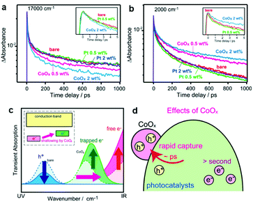 | ||
Fig. 10 Decay of transient absorption at (a) 17![[thin space (1/6-em)]](https://www.rsc.org/images/entities/char_2009.gif) 000 cm−1 and (b) 2000 cm−1 for bare, CoOx-loaded, and Pt-loaded LaTiO2N after excited by 500 nm laser pulses; (c and d) schematics showing the change in carrier dynamics upon CoOx CC loading. Adapted with permission from ref. 157; copyright 2014 ACS. 000 cm−1 and (b) 2000 cm−1 for bare, CoOx-loaded, and Pt-loaded LaTiO2N after excited by 500 nm laser pulses; (c and d) schematics showing the change in carrier dynamics upon CoOx CC loading. Adapted with permission from ref. 157; copyright 2014 ACS. | ||
4.2 Assessment of CC activity
In addition to the interfacial carrier dynamics, the intrinsic electrocatalytic activity of the CC material is still a significant descriptor of photocatalytic and PEC performance. Since the CCs serve as highly-active sites to drive redox reactions (like ECs), an understanding and evaluation of their intrinsic HER and OER activities are requisite for enhancing the catalytic performance. Notably, their catalytic activities can be measured with a CC-loaded electrode using an electrochemical system. In EC studies, the catalytic activities are typically monitored under strong acidic or alkaline conditions, which are advantageous in showing their maximum activities. However, such extreme pH conditions cannot be applied in photocatalytic and PEC systems because they would likely cause chemical damage to the semiconductor.158 Since the stability of the photoactive semiconductor is the top priority for water splitting, it is important to conduct assessments at a practically-applicable pH. Even if an EC exhibits excellent performance under specific pH conditions, that same material might not be equally effective as CCs under different pH conditions.159 Therefore, it is necessary to examine the CC performance in an environment similar to that optimized for the photocatalytic and PEC systems. For example, based on the synergistic improvement of OER activity by a bimetallic Co–Mn oxide EC,160 our group investigated the effect of Co doping on the catalytic OER activity of Mn3O4 NPs on the SrTiO3 PC, and found that increasing the Co doping content improved the water-splitting activity (Fig. 11).145 By measuring the OER activity of a CoxMn3−xO4 NP-loaded electrode in neutral pH [0.1 M phosphate buffer solution (PBS)], we found that the Co content monotonically enhanced the OER activity (Fig. 11d). The calculated band structure of the CoxMn3−xO4 NPs had similar valence band levels, regardless of the Co content, which indicated that the enhanced OER kinetics achieved by the Co-doping in Mn3O4 CC primarily contributed to boosting the overall photocatalytic water-splitting activity by accelerating slow OER process (Fig. 11e). Electrochemical assessments under similar conditions as those used for the photocatalytic and PEC systems can offer more accurate predictions of an EC's suitability as a CC. Recently reported ECs that are active over universal pH represent promising candidates as CCs in various photocatalytic and PEC environments.161–163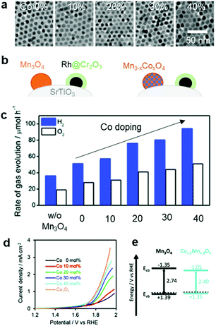 | ||
| Fig. 11 Co-doping effect on the overall water-splitting activity of SrTiO3: (a) TEM images of Mn3O4 doped with various Co concentrations; (b) schematic of CC-loaded photocatalyst; (c) photocatalytic trend as a function of Co dopant concentration in Mn3O4 CCs; (d) electrochemical OER activities of CoxMn3−xO4 NPs in a neutral electrolyte (0.1 M PBS); (e) calculated band structures of Mn3O4 and CoxMn3−xO4 NPs. Adapted with permission from ref. 145; copyright 2018 RSC. | ||
4.3 Prevention of backward reaction
The oxygen reduction reaction (ORR) is usually not an issue to consider for electrochemical systems because they employ a divided cell configuration, wherein the HER and OER electrodes are placed in separated cells. However, the ORR must be considered in overall water splitting using powdered PCs because both half-reactions take place in a single reactor. Outstanding HER CCs, such as Pt and Rh metals, tend to actively catalyse the ORR,22 which consumes the H2 and O2 evolved during the photocatalysis, thus reducing the H2 uptake.164 Strategies to effectively suppress this backward reaction and increase the quantity of evolved H2 include the application of protective coatings on the CCs (e.g., amorphous oxides such as CrOx,165 TaOx,166 SiOx,167 and ZrOx (ref. 168 and 169)). Our electrochemical measurements demonstrated that the ZrOx matrix could suppress the ORR of Rh3+ active sites, which confirmed the O2-blocking ability of ZrOx (Fig. 12a) and prevented the loss of H2-uptake in photocatalytic overall water splitting by ZrRhOx/SrTiO3:Al (Fig. 12b). Evaluating the ORR activities of CC materials in addition to their HER and OER activities can provide insights relevant for improving the total photocatalytic activity.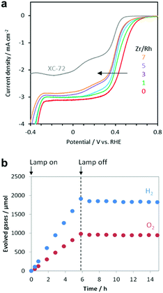 | ||
Fig. 12 (a) Current–potential curves of RhZrOx (Zr/Rh: 0–7 w/w)-loaded carbon supports in O2-saturated 1 M Na2SO4 (pH 7); (b) gas evolution over time by RhZrOx/SrTiO3:Al (Rh = 0.1 wt% and Zr = 0.5 wt% vs. SrTiO3![[thin space (1/6-em)]](https://www.rsc.org/images/entities/char_2009.gif) : :![[thin space (1/6-em)]](https://www.rsc.org/images/entities/char_2009.gif) Al) during and after light irradiation (300 W Xe lamp). Adapted with permission from ref. 169; copyright 2020 RSC. Al) during and after light irradiation (300 W Xe lamp). Adapted with permission from ref. 169; copyright 2020 RSC. | ||
4.4 Structural and chemical transformations of CCs during photocatalysis
Similar to ECs, nanosized CCs can undergo structural and chemical transformations during photocatalytic and PEC water-splitting. In fact, our group's study revealed that the NiPx@FePyOz CCs on BiVO4 PE transformed into NiFeOOH based on post-OER characterizations with X-ray photoelectron spectroscopy (XPS) and Fourier transform infrared spectroscopy (FTIR).148 We also observed a compositional change in the novel Rh–Cl–Zr–O CCs deposited on SrTiO3:Al PCs under operating conditions. After the photocatalysis, XPS analyses detected the removal of Cl from the initial Rh–Cl–Zr–O CC to form RhZrOx during photocatalysis.169 These results indicated the importance of post-catalysis characterization in determining the actual active species. Additionally, in situ/operando characterization techniques are powerful tools for monitoring the temporal evolution of CCs under the relevant working conditions, and they can help us to deeply understand the transformation mechanism of CCs.170 Recently, synchrotron-based characterizations have provided valuable data with high temporal resolution, even for a small concentration of CCs. Altomare and co-workers conducted operando X-ray absorption spectroscopy (XAS) experiments for CuNi CCs loaded onto TiO2 during photocatalysis (Fig. 13a).171 At the early stage of the reaction, the preformed CuOx and NiO species were reduced to metallic Cu and Ni, thus forming CuNi alloy CCs (Fig. 13b–e). Subsequently, the H2 evolution rate increased as the transformation progressed, which identified the metallic CuNi as the actual active sites. Operando XAS can also be used to confirm the stability of CCs in a sustained catalytic setting. Fundamentally, the integrated utilization of the methods discussed here is highly desirable to accelerate progress in designing highly-active CC materials.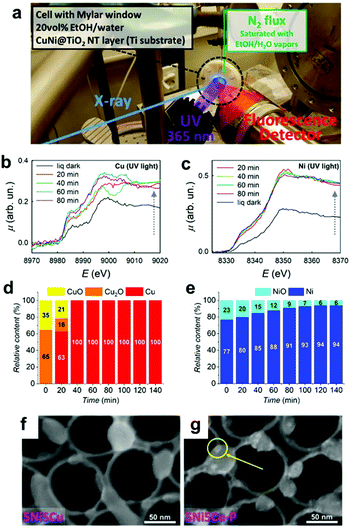 | ||
| Fig. 13 (a) Operando XAS experimental setup; (b) Cu K-edge and (c) Ni K-edge XAS spectra of 5Ni5Cu–TiO2 in a water−ethanol under UV irradiation for various exposure times; (d) Cu and (e) Ni phase contents determined by operando XAS for 5Ni5Cu–TiO2; SEM images of 5Ni5Cu–TiO2 (f) before and (g) after photocatalysis (a yellow circle indicates metallic NPs deposited under the UV irradiation). Adapted with permission from ref. 171; copyright 2020 ACS. | ||
5. Conclusions and outlook
In this perspective, we have discussed recent developments in EC materials and their application as CCs in photocatalytic and PEC water-splitting systems. Although significant efforts have already been directed toward the construction of high-performance CC/PC and CC/PEC composites, exploration of CC materials still lags its EC counterpart. If methodologies to properly hybridize active EC materials with a variety of photoactive semiconductors (including unstable chalcogenides and nitrides) are developed, the accumulated knowledge regarding ECs will dramatically accelerate advances in photocatalytic and PEC systems. We believe that the colloidal approach using NPs of active EC materials with controllable sizes and compositions represents a promising solution to bridge the studies of ECs and CCs.However, there are urgent issues that must be overcome in order to further enhance their photocatalytic performance. For particulate PC systems, spatial separation of HER and OER sites is highly desirable to efficiently promote both half-reactions. Facet-selective photodeposition of HER and OER CCs has been realized on PCs (e.g., SrTiO3:Al and BiVO4) by utilizing the intrinsic built-in potential generated from the work function difference between the PC crystal planes.76,115 To realize such site-specific CC deposition in other loading methods, exploiting the preferential adsorption of surfactants on different crystal planes of PCs could be useful.172 The surfactants on CC precursor complex or NP surface have functional groups that could interact with coordinatively unsaturated atoms on the PC surface via dynamic adsorption and desorption. Again, the distinct atomic arrangement on the crystal facets of PCs might affect the binding affinities of incoming functional groups. For example, the (111) surface of Cu2O PCs contains more Cu dangling bonds that can be passivated by polar functional ligands.173 In turn, CCs could be preferentially loaded on the exposed (100) surface of Cu2O through proper linker molecules. Likewise, PtCl62− interacted strongly with OH groups on the anatase TiO2 (101) surface, whereas Pt(NH3)42+ does not.174 As such, this strategy can only be implemented on limited PCs and CCs, thus expanding the library of applicable materials is of primary importance to improve the poor STH efficiencies in PC systems.
Another crucial factor that needs to be taken into account is the formation of an intimate interfacial contact between CCs and semiconductors. Although CCs are usually loaded on as-prepared PC powder and PEs, the presence of pre-existing defective and/or insulative oxide layers on the semiconductor surface might cause charge recombination and/or carrier transfer blocking, and therefore should be removed before CC deposition.175 Acid treatment is a simple and effective way to dissolve such surface oxide layers.175
Ensuring long-term durability of CCs is also critical in maintaining excellent photocatalytic performance over extended operation periods. Since small amount of CCs is usually loaded on NPs or thin films, CC degradation can potentially occur during photocatalysis through dissolution and physical removal.125 The loss of carrier extraction capability of CCs could lead to self-corrosion of PCs due to uncompensated total charge.19 Employing newly developed efficient and durable multi-metallic compound EC materials as CCs is a straightforward but promising way in accelerating the discovery of high-performance PC/CC combinations. Aside from improving the chemical and physical durability, CC regeneration by feeding CC precursor during operation could be a logical solution in prolonging the lifetime of practical photocatalytic systems.176
As stated from Section 3, the need to control the CC morphology, internal electronic structure, and intrinsic surface catalytic activity, in addition to the CC's interfacial structure with the semiconductors, make advancements in this field challenging. However, recent advances in characterization techniques such as ultrafast spectroscopy and synchrotron-based in situ analyses have gradually revealed the crucial role of such factors in determining the bottlenecks of photocatalytic systems. In addition to developing these technologies, acquiring fundamental properties from basic electrocatalytic analysis and theoretical DFT and ab initio calculation can potentially contribute to the understanding and construction of a sustainable and highly-efficient solar-driven photocatalytic water-splitting system.
Author contributions
MS conceived the topic and structure of the work. All the authors contributed to the discussion, writing, editing, and revision of this work.Conflicts of interest
There are no conflicts to declare.Acknowledgements
This work was partly supported by the Artificial Photosynthesis Project of the New Energy and Industrial Technology Development Organization (NEDO) of Japan and Japan Society for the Promotion of Science (JSPS) KAKENHI for Scientific Research S (Grant No. JP19H0563) (T. T.), and Challenging Research (Exploratory) (Grant No. JP20K21236) (M. S.). We thank Suzanne Adam, PhD, from Edanz (https://jp.edanz.com/ac) for editing a draft of this manuscript.References
- T. M. L. Wigley, Clim. Chang., 2017, 147, 31–45 CrossRef.
- S. C. Peter, ACS Energy Lett, 2018, 3, 1557–1561 CrossRef CAS.
- N. Sánchez-Bastardo, R. Schlögl and H. Ruland, Ind. Eng. Chem. Res., 2021, 60, 11855–11881 CrossRef.
- Y. Nonobe, IEEJ Trans. Electr. Electron. Eng., 2017, 12, 5–9 CrossRef CAS.
- U. P. M. Ashik, W. M. A. Wan Daud and H. F. Abbas, Renew. Sustain. Energy Rev., 2015, 44, 221–256 CrossRef CAS.
- S. Dutta, Energy Fuels, 2021, 35, 11613–11639 CrossRef CAS.
- M. R. Shaner, H. A. Atwater, N. S. Lewis and E. W. McFarland, Energy Environ. Sci., 2016, 9, 2354–2371 RSC.
- J. Jia, L. C. Seitz, J. D. Benck, Y. Huo, Y. Chen, J. W. D. Ng, T. Bilir, J. S. Harris and T. F. Jaramillo, Nat. Commun., 2016, 7, 1–6 Search PubMed.
- S. Wang, A. Lu and C.-J. Zhong, Nano Convergence, 2021, 8, 1–23 CrossRef CAS PubMed.
- Q. Wang and K. Domen, Chem. Rev., 2019, 120, 919–985 CrossRef PubMed.
- D. Kang, T. W. Kim, S. R. Kubota, A. C. Cardiel, H. G. Cha and K.-S. Choi, Chem. Rev., 2015, 115, 12839–12887 CrossRef CAS PubMed.
- T. Hisatomi and K. Domen, Nat. Catal., 2019, 2, 387–399 CrossRef CAS.
- H. Nishiyama, T. Yamada, M. Nakabayashi, Y. Maehara, M. Yamaguchi, Y. Kuromiya, H. Tokudome, S. Akiyama, T. Watanabe, R. Narushima, S. Okunaka, N. Shibata, T. Takata, T. Hisatomi and K. Domen, Nature, 2021, 598, 304–307 CrossRef CAS PubMed.
- C. Jiang, S. J. A. Moniz, A. Wang, T. Zhang and J. Tang, Chem. Soc. Rev., 2017, 46, 4645–4660 RSC.
- H. Wu, H. L. Tan, C. Y. Toe, J. Scott, L. Wang, R. Amal and Y. H. Ng, Adv. Mater., 2020, 32, 1–21 Search PubMed.
- T. Higashi, H. Nishiyama, Y. Suzuki, Y. Sasaki, T. Hisatomi, M. Katayama, T. Minegishi, K. Seki, T. Yamada and K. Domen, Angew. Chem., Int. Ed., 2019, 58, 2300–2304 CrossRef CAS PubMed.
- J. Yang, D. Wang, H. Han and C. Li, Acc. Chem. Res., 2013, 46, 1900–1909 CrossRef CAS PubMed.
- K. Takanabe, ACS Catal., 2017, 7, 8006–8022 CrossRef CAS.
- X. Ning and G. Lu, Nanoscale, 2020, 12, 1213–1223 RSC.
- J. Ran, J. Zhang, J. Yu, M. Jaroniec and S. Z. Qiao, Chem. Soc. Rev., 2014, 43, 7787–7812 RSC.
- W. Qiao, H. B. Tao, B. Liu and J. Chen, Small, 2019, 15, 1804391 CrossRef PubMed.
- Z. W. Seh, J. Kibsgaard, C. F. Dickens, I. Chorkendorff, J. K. Nørskov and T. F. Jaramillo, Science, 2017, 355, 6321 CrossRef PubMed.
- J. Zhu, L. Hu, P. Zhao, L. Y. S. Lee and K. Y. Wong, Chem. Rev., 2020, 120, 851–918 CrossRef CAS PubMed.
- J. Song, C. Wei, Z.-F. Huang, C. Liu, L. Zeng, X. Wang and Z. J. Xu, Chem. Soc. Rev., 2020, 49, 2196–2214 RSC.
- J. K. Nørskov, T. Bligaard, A. Logadottir, J. R. Kitchin, J. G. Chen, S. Pandelov and U. Stimming, J. Electrochem. Soc., 2005, 152, J23 CrossRef.
- T. F. Jaramillo, K. P. Jørgensen, J. Bonde, J. H. Nielsen, S. Horch and I. Chorkendorff, Science, 2007, 317, 100–102 CrossRef CAS PubMed.
- P. Liu, J. Zhu, J. Zhang, P. Xi, K. Tao, D. Gao and D. Xue, ACS Energy Lett, 2017, 2, 745–752 CrossRef CAS.
- Y. Chen, K. Yang, B. Jiang, J. Li, M. Zeng and L. Fu, J. Mater. Chem. A, 2017, 5, 8187–8208 RSC.
- S. M. El-Refaei, P. A. Russo and N. Pinna, ACS Appl. Mater. Interfaces, 2021, 13, 22077–22097 CrossRef CAS PubMed.
- Y. Jiang and Y. Lu, Nanoscale, 2020, 12, 9327–9351 RSC.
- M. Kuang, W. Huang, C. Hegde, W. Fang, X. Tan, C. Liu, J. Ma and Q. Yan, Mater. Horizons, 2020, 7, 32–53 RSC.
- G. Fu and J.-M. Lee, J. Mater. Chem. A, 2019, 7, 9386–9405 RSC.
- C. Tang, L. Gan, R. Zhang, W. Lu, X. Jiang, A. M. Asiri, X. Sun, J. Wang and L. Chen, Nano Lett., 2016, 16, 6617–6621 CrossRef CAS PubMed.
- I. H. Kwak, I. S. Kwon, T. T. Debela, H. G. Abbas, Y. C. Park, J. Seo, J.-P. Ahn, J. H. Lee, J. Park and H. S. Kang, ACS Nano, 2020, 14, 11995–12005 CrossRef CAS PubMed.
- A. A. Rezaie, E. Lee, D. Luong, J. A. Yapo and B. P. T. Fokwa, ACS Mater. Lett., 2021, 3, 313–319 CrossRef CAS.
- S. H. Park, T. H. Jo, M. H. Lee, K. Kawashima, C. B. Mullins, H.-K. Lim and D. H. Youn, J. Mater. Chem. A, 2021, 9, 4945–4951 RSC.
- X. Zheng, Y. Chen, X. Bao, S. Mao, R. Fan and Y. Wang, ACS Catal., 2020, 10, 11634–11642 CrossRef CAS.
- S. Zhao, J. Berry-Gair, W. Li, G. Guan, M. Yang, J. Li, F. Lai, F. Corà, K. Holt, D. J. L. Brett, G. He and I. P. Parkin, Adv. Sci., 2020, 7, 1903674 CrossRef CAS PubMed.
- T. Naito, T. Shinagawa, T. Nishimoto and K. Takanabe, Inorg. Chem. Front., 2021, 8, 2900–2917 RSC.
- H. Over, ACS Catal., 2021, 11, 8848–8871 CrossRef CAS.
- P. M. Bodhankar, P. B. Sarawade, G. Singh, A. Vinu and D. S. Dhawale, J. Mater. Chem. A, 2021, 9, 3180–3208 RSC.
- M. E. C. Pascuzzi, A. J. W. Man, A. Goryachev, J. P. Hofmann and E. J. M. Hensen, Catal. Sci. Technol., 2020, 10, 5593–5601 RSC.
- I. C. Man, H.-Y. Su, F. Calle-Vallejo, H. A. Hansen, J. I. Martínez, N. G. Inoglu, J. Kitchin, T. F. Jaramillo, J. K. Nørskov and J. Rossmeisl, ChemCatChem, 2011, 3, 1159–1165 CrossRef CAS.
- B. Zhang, X. Zheng, O. Voznyy, R. Comin, M. Bajdich, M. García-Melchor, L. Han, J. Xu, M. Liu, L. Zheng, F. P. G. de Arquer, C. T. Dinh, F. Fan, M. Yuan, E. Yassitepe, N. Chen, T. Regier, P. Liu, Y. Li, P. De Luna, A. Janmohamed, H. L. Xin, H. Yang, A. Vojvodic and E. H. Sargent, Science, 2016, 352, 333–337 CrossRef CAS PubMed.
- S. Kim, H. Mizuno, M. Saruyama, M. Sakamoto, M. Haruta, H. Kurata, T. Yamada, K. Domen and T. Teranishi, Chem. Sci., 2020, 11, 1523–1530 RSC.
- S. Anantharaj, S. R. Ede, K. Sakthikumar, K. Karthick, S. Mishra and S. Kundu, ACS Catal., 2016, 6, 8069–8097 CrossRef CAS.
- T. Zhang, Y. Zhu and J. Y. Lee, J. Mater. Chem. A, 2018, 6, 8147–8158 RSC.
- X. Shang, J.-H. Tang, B. Dong and Y. Sun, Sustain. Energy Fuels, 2020, 4, 3211–3228 RSC.
- G. Zhang, Y. Li, X. Xiao, Y. Shan, Y. Bai, H.-G. Xue, H. Pang, Z. Tian and Q. Xu, Nano Lett., 2021, 21, 3016–3025 CrossRef CAS PubMed.
- D. Guan, G. Ryu, Z. Hu, J. Zhou, C.-L. Dong, Y.-C. Huang, K. Zhang, Y. Zhong, A. C. Komarek, M. Zhu, X. Wu, C.-W. Pao, C.-K. Chang, H.-J. Lin, C.-T. Chen, W. Zhou and Z. Shao, Nat. Commun., 2020, 11, 3376 CrossRef PubMed.
- M. Cui, C. Yang, B. Li, Q. Dong, M. Wu, S. Hwang, H. Xie, X. Wang, G. Wang and L. Hu, Adv. Energy Mater., 2021, 11, 2002887 CrossRef CAS.
- F. Dionigi and P. Strasser, Adv. Energy Mater., 2016, 6, 1600621 CrossRef.
- D. Liu, H. Ai, J. Li, M. Fang, M. Chen, D. Liu, X. Du, P. Zhou, F. Li, K. H. Lo, Y. Tang, S. Chen, L. Wang, G. Xing and H. Pan, Adv. Energy Mater., 2020, 10, 2002464 CrossRef CAS.
- M. Y. Zu, C. Wang, L. Zhang, L. R. Zheng and H. G. Yang, Mater. Horizons, 2019, 6, 115–121 RSC.
- Y. Zhu, W. Zhou, Y. Zhong, Y. Bu, X. Chen, Q. Zhong, M. Liu and Z. Shao, Adv. Energy Mater., 2017, 7, 1602122 CrossRef.
- D. Wu, K. Kusada, S. Yoshioka, T. Yamamoto, T. Toriyama, S. Matsumura, Y. Chen, O. Seo, J. Kim, C. Song, S. Hiroi, O. Sakata, T. Ina, S. Kawaguchi, Y. Kubota, H. Kobayashi and H. Kitagawa, Nat. Commun., 2021, 12, 1145 CrossRef CAS PubMed.
- J. Zhang, T. Wang, D. Pohl, B. Rellinghaus, R. Dong, S. Liu, X. Zhuang and X. Feng, Angew. Chem., Int. Ed., 2016, 55, 6702–6707 CrossRef CAS PubMed.
- H. Xu, J. Wei, K. Zhang, Y. Shiraishi and Y. Du, ACS Appl. Mater. Interfaces, 2018, 10, 29647–29655 CrossRef CAS PubMed.
- C. Zhu, Z. Yin, W. Lai, Y. Sun, L. Liu, X. Zhang, Y. Chen and S. L. Chou, Adv. Energy Mater., 2018, 8, 1802327 CrossRef.
- J. Jiang, Q. Liu, C. Zeng and L. Ai, J. Mater. Chem. A, 2017, 5, 16929–16935 RSC.
- B. Xiong, L. Chen and J. Shi, ACS Catal., 2018, 8, 3688–3707 CrossRef CAS.
- C. C. L. McCrory, S. Jung, J. C. Peters and T. F. Jaramillo, J. Am. Chem. Soc., 2013, 135, 16977–16987 CrossRef CAS PubMed.
- M. Wang, L. Zhang, Y. He and H. Zhu, J. Mater. Chem. A, 2021, 9, 5320–5363 RSC.
- Y. Garsany, O. A. Baturina, K. E. Swider-Lyons and S. S. Kocha, Anal. Chem., 2010, 82, 6321–6328 CrossRef CAS PubMed.
- N. K. Chaudhari, H. Jin, B. Kim and K. Lee, Nanoscale, 2017, 9, 12231–12247 RSC.
- Y. Garsany, O. A. Baturina, K. E. Swider-Lyons and S. S. Kocha, Anal. Chem., 2010, 82, 6321–6328 CrossRef CAS PubMed.
- C. Zhu, Q. Shi, S. Feng, D. Du and Y. Lin, ACS Energy Lett, 2018, 3, 1713–1721 CrossRef CAS.
- M. B. Stevens, L. J. Enman, A. S. Batchellor, M. R. Cosby, A. E. Vise, C. D. M. Trang and S. W. Boettcher, Chem. Mater., 2016, 29, 120–140 CrossRef.
- S. Jin, ACS Energy Lett, 2017, 2, 1937–1938 CrossRef CAS.
- W. Li, D. Xiong, X. Gao and L. Liu, Chem. Commun., 2019, 55, 8744–8763 RSC.
- P. Chen, K. Xu, Z. Fang, Y. Tong, J. Wu, X. Lu, X. Peng, H. Ding, C. Wu and Y. Xie, Angew. Chem., Int. Ed., 2015, 54, 14710–14714 CrossRef CAS PubMed.
- W. Cai, R. Chen, H. Yang, H. B. Tao, H.-Y. Wang, J. Gao, W. Liu, S. Liu, S.-F. Hung and B. Liu, Nano Lett., 2020, 20, 4278–4285 CrossRef CAS PubMed.
- J. Xiao, J. J. M. Vequizo, T. Hisatomi, J. Rabeah, M. Nakabayashi, Z. Wang, Q. Xiao, H. Li, Z. Pan, M. Krause, N. Yin, G. Smith, N. Shibata, A. Brückner, A. Yamakata, T. Takata and K. Domen, J. Am. Chem. Soc., 2021, 143, 10059–10064 CrossRef CAS PubMed.
- S. Bai, W. Yin, L. Wang, Z. Li and Y. Xiong, RSC Adv., 2016, 6, 57446–57463 RSC.
- Y. Hosogi, Y. Shimodaira, H. Kato, H. Kobayashi and A. Kudo, Chem. Mater., 2008, 20, 1299–1307 CrossRef CAS.
- T. Takata, J. Jiang, Y. Sakata, M. Nakabayashi, N. Shibata, V. Nandal, K. Seki, T. Hisatomi and K. Domen, Nature, 2020, 581, 411–414 CrossRef CAS PubMed.
- J. Zhao, B. Fu, X. Li, Z. Ge, B. Ma and Y. Chen, ACS Appl. Energy Mater., 2020, 3, 10910–10919 CrossRef CAS.
- D. Ren, Z. Z. Liang, Y. H. Ng, P. Zhang, Q. Xiang and X. Li, Chem. Eng. J., 2020, 390, 124496 CrossRef CAS.
- X. Lu, J. Xie, S. Liu, A. Adamski, X. Chen and X. Li, ACS Sustain. Chem. Eng., 2018, 6, 13140–13150 CrossRef CAS.
- L. Tian, S. Min, F. Wang and Z. Zhang, J. Phys. Chem. C, 2019, 123, 28640–28650 CrossRef.
- D. Ren, Z. Z. Liang, Y. H. Ng, P. Zhang, Q. Xiang and X. Li, Chem. Eng. J., 2020, 390, 124496 CrossRef CAS.
- J. Zhang, W. Yao, C. Huang, P. Shi and Q. Xu, J. Mater. Chem. A, 2017, 5, 12513–12519 RSC.
- Z. Qin, Y. Chen, Z. Huang, J. Su and L. Guo, J. Mater. Chem. A, 2017, 5, 19025–19035 RSC.
- C. Cheng, S. Zong, J. Shi, F. Xue, Y. Zhang, X. Guan, B. Zheng, J. Deng and L. Guo, Appl. Catal. B Environ., 2020, 265, 118620 CrossRef CAS.
- W. Zhong, W. Tu, S. Feng and A. Xu, J. Alloys Compd., 2019, 772, 669–674 CrossRef CAS.
- R. M. Irfan, M. H. Tahir, S. Iqbal, M. Nadeem, T. Bashir, M. Maqsood, J. Zhao and L. Gao, J. Mater. Chem. C, 2021, 9, 3145–3154 RSC.
- Z.-K. Shen, Y.-J. Yuan, P. Wang, W. Bai, L. Pei, S. Wu, Z.-T. Yu and Z. Zou, ACS Appl. Mater. Interfaces, 2020, 12, 17343–17352 CrossRef CAS PubMed.
- H. Du, H.-L. Guo, Y.-N. Liu, X. Xie, K. Liang, X. Zhou, X. Wang and A.-W. Xu, ACS Appl. Mater. Interfaces, 2016, 8, 4023–4030 CrossRef CAS PubMed.
- Y. Liu, B. Wang, Q. Zhang, S. Yang, Y. Li, J. Zuo, H. Wang and F. Peng, Green Chem., 2020, 22, 238–247 RSC.
- X. Sun and H. Du, ACS Sustain. Chem. Eng., 2019, 7, 16320–16328 CrossRef CAS.
- K. Chang, Z. Mei, T. Wang, Q. Kang, S. Ouyang and J. Ye, ACS Nano, 2014, 8, 7078–7087 CrossRef CAS PubMed.
- Y. Liu, B. Wang, Q. Zhang, S. Yang, Y. Li, J. Zuo, H. Wang and F. Peng, Green Chem., 2020, 22, 238–247 RSC.
- Y. Chao, J. Zheng, H. Zhang, Y. Ma, F. Li, Y. Tan and Z. Zhu, Energy Technol., 2018, 6, 2132–2138 CrossRef CAS.
- B. Ma, Y. Liu, J. Li, K. Lin, W. Liu and H. Zhan, Int. J. Hydrogen Energy, 2016, 41, 22009–22016 CrossRef CAS.
- X. Liang, J. Xie, J. Xiong, L. Gong and C. M. Li, Sustain. Energy Fuels, 2018, 2, 2053–2059 RSC.
- Y. Pihosh, V. Nandal, T. Minegishi, M. Katayama, T. Yamada, K. Seki, M. Sugiyama and K. Domen, ACS Energy Lett, 2020, 5, 2492–2497 CrossRef CAS.
- X. Zong, J. Han, G. Ma, H. Yan, G. Wu and C. Li, J. Phys. Chem. C, 2011, 115, 12202–12208 CrossRef CAS.
- X. Zong, J. Han, G. Ma, H. Yan, G. Wu and C. Li, J. Phys. Chem. C, 2011, 115, 12202–12208 CrossRef CAS.
- J. Chu, G. Sun, X. Han, X. Chen, J. Wang, W. Hu, I. Waluyo, A. Hunt, Y. Du, B. Song and P. Xu, Nanoscale, 2019, 11, 15633–15640 RSC.
- K. Maeda, K. Teramura, D. Lu, T. Takata, N. Saito, Y. Inoue and K. Domen, J. Phys. Chem. B, 2006, 110, 13753–13758 CrossRef CAS PubMed.
- E. Tsuji, R. Nanbu, Y. Degami, K. Hirao, T. Watanabe, N. Matsumoto, S. Suganuma and N. Katada, Part. Part. Syst. Charact., 2020, 37, 2000053 CrossRef CAS.
- Y. Negishi, Y. Matsuura, R. Tomizawa, W. Kurashige, Y. Niihori, T. Takayama, A. Iwase and A. Kudo, J. Phys. Chem. C, 2015, 119, 11224–11232 CrossRef CAS.
- L. Wei, Z. Liu, Z. Guo, M. Ruan, Y. Meng and W. Yan, ACS Appl. Energy Mater., 2021, 4, 7233–7241 CrossRef CAS.
- Z. Qin, Y. Chen, X. Wang, X. Guo and L. Guo, ACS Appl. Mater. Interfaces, 2016, 8, 1264–1272 CrossRef CAS PubMed.
- S. Meng, Y. Cui, H. Wang, X. Zheng, X. Fu and S. Chen, Dalton Trans., 2018, 47, 12671–12683 RSC.
- S. Guan, X. Fu, Y. Zhang and Z. Peng, Chem. Sci., 2018, 9, 1574–1585 RSC.
- X. L. Yin, L. L. Li, W. J. Jiang, Y. Zhang, X. Zhang, L. J. Wan and J. S. Hu, ACS Appl. Mater. Interfaces, 2016, 8, 15258–15266 CrossRef CAS PubMed.
- X. Liu, Y. Zhao, X. Yang, Q. Liu, X. Yu, Y. Li, H. Tang and T. Zhang, Appl. Catal. B Environ., 2020, 275, 119144 CrossRef CAS.
- J. Dong, Y. Shi, C. Huang, Q. Wu, T. Zeng and W. Yao, Appl. Catal. B Environ., 2019, 243, 27–35 CrossRef CAS.
- X. Hong, X. Yu, L. Wang, Q. Liu, J. Sun and H. Tang, Inorg. Chem., 2021, 60, 12506–12516 CrossRef CAS PubMed.
- Y. Zhao, Y. Lu, L. Chen, X. Wei, J. Zhu and Y. Zheng, ACS Appl. Mater. Interfaces, 2020, 12, 46073–46083 CrossRef CAS PubMed.
- K. Wenderich and G. Mul, Chem. Rev., 2016, 116, 14587–14619 CrossRef CAS PubMed.
- Z. Wang, Y. Inoue, T. Hisatomi, R. Ishikawa, Q. Wang, T. Takata, S. Chen, N. Shibata, Y. Ikuhara and K. Domen, Nat. Catal., 2018, 1, 756–763 CrossRef CAS.
- G. Ma, J. Liu, T. Hisatomi, T. Minegishi, Y. Moriya, M. Iwase, H. Nishiyama, M. Katayama, T. Yamada and K. Domen, Chem. Commun., 2015, 51, 4302–4305 RSC.
- R. Li, F. Zhang, D. Wang, J. Yang, M. Li, J. Zhu, X. Zhou, H. Han and C. Li, Nat. Commun., 2013, 4, 1–7 Search PubMed.
- I. Vamvasakis, I. T. Papadas, T. Tzanoudakis, C. Drivas, S. A. Choulis, S. Kennou and G. S. Armatas, ACS Catal., 2018, 8, 8726–8738 CrossRef CAS.
- W. Liu, X. Wang, H. Yu and J. Yu, ACS Sustain. Chem. Eng., 2018, 6, 12436–12445 CrossRef CAS.
- Y. Dong, L. Kong, P. Jiang, G. Wang, N. Zhao, H. Zhang and B. Tang, ACS Sustain. Chem. Eng., 2017, 5, 6845–6853 CrossRef CAS.
- X. Lu, C. Ying Toe, F. Ji, W. Chen, X. Wen, R. J. Wong, J. Seidel, J. Scott, J. N. Hart and Y. H. Ng, ACS Appl. Mater. Interfaces, 2020, 12, 8324–8332 CrossRef CAS PubMed.
- S. Min, Y. Lei, H. Sun, J. Hou, F. Wang, E. Cui, S. She, Z. Jin, J. Xu and X. Ma, Mol. Catal., 2017, 440, 190–198 CrossRef CAS.
- T. Di, B. Zhu, J. Zhang, B. Cheng and J. Yu, Appl. Surf. Sci., 2016, 389, 775–782 CrossRef CAS.
- K.-Q. Lu, M.-Y. Qi, Z.-R. Tang and Y.-J. Xu, Langmuir, 2019, 35, 11056–11065 CrossRef CAS PubMed.
- F. E. Osterloh, Chem. Soc. Rev., 2013, 42, 2294–2320 RSC.
- R. Hu, L. Meng, J. Zhang, X. Wang, S. Wu, Z. Wu, R. Zhou, L. Li, D. S. Li and T. Wu, Nanoscale, 2020, 12, 8875–8882 RSC.
- Y. Pihosh, T. Minegishi, V. Nandal, T. Higashi, M. Katayama, T. Yamada, Y. Sasaki, K. Seki, Y. Suzuki, M. Nakabayashi, M. Sugiyama and K. Domen, Energy Environ. Sci., 2020, 13, 1519–1530 RSC.
- X. Zhong, H. He, J. Du, Q. Ren, J. Huang, Y. Tang, J. Wang, L. Yang, F. Dong, L. Bian and Y. Zhou, Electrochim. Acta, 2019, 304, 301–311 CrossRef CAS.
- S. S. M. Bhat, S. A Lee, T. H. Lee, C. Kim, J. Park, T.-W. Lee, S. Y. Kim and H. W. Jang, ACS Appl. Energy Mater., 2020, 3, 5646–5656 CrossRef CAS.
- D. He, R. T. Gao, S. Liu, M. Sun, X. Liu, K. Hu, Y. Su and L. Wang, ACS Catal., 2020, 10, 10570–10576 CrossRef CAS.
- R. T. Gao, L. Wu, S. Liu, K. Hu, X. Liu, J. Zhang and L. Wang, J. Mater. Chem. A, 2021, 9, 6298–6305 RSC.
- L. Wang, F. Dionigi, N. Truong Nguyen, R. Kirchgeorg, M. Gliech, S. Grigorescu, P. Strasser and P. Schmuki, Chem. Mater., 2015, 27, 2360–2366 CrossRef CAS.
- M. W. Kanan and D. G. Nocera, Science, 2008, 321, 1072–1075 CrossRef CAS PubMed.
- J. Zhang, Y. Huang, X. Lu, J. Yang and Y. Tong, ACS Sustain. Chem. Eng., 2021, 9, 8306–8314 CrossRef CAS.
- A. A. Haleem, S. Majumder, N. Perumandla, Z. N. Zahran and Y. Naruta, J. Phys. Chem. C, 2017, 121, 20093–20100 CrossRef.
- J. Seo, T. Takata, M. Nakabayashi, T. Hisatomi, N. Shibata, T. Minegishi and K. Domen, J. Am. Chem. Soc., 2015, 137, 12780–12783 CrossRef CAS PubMed.
- Y. Gao, G. Yang, Y. Dai, X. Li, J. Gao, N. Li, P. Qiu and L. Ge, ACS Appl. Mater. Interfaces, 2020, 12, 17364–17375 CrossRef CAS PubMed.
- T. W. Kim and K. S. Choi, Science, 2014, 343, 990–994 CrossRef CAS PubMed.
- L. Wang, F. Dionigi, N. Truong Nguyen, R. Kirchgeorg, M. Gliech, S. Grigorescu, P. Strasser and P. Schmuki, Chem. Mater., 2015, 27, 2360–2366 CrossRef CAS.
- A. A. Haleem, N. Perumandla and Y. Naruta, ACS Omega, 2019, 4, 7815–7821 CrossRef PubMed.
- J. Chang and E. R. Waclawik, RSC Adv., 2014, 4, 23505–23527 RSC.
- M. S. Bakshi, Cryst. Growth Des., 2015, 16, 1104–1133 CrossRef.
- N. Sakamoto, H. Ohtsuka, T. Ikeda, K. Maeda, D. Lu, M. Kanehara, K. Teramura, T. Teranishi and K. Domen, Nanoscale, 2009, 1, 106–109 RSC.
- K. Maeda, N. Sakamoto, T. Ikeda, H. Ohtsuka, A. Xiong, D. Lu, M. Kanehara, T. Teranishi and K. Domen, Chem. –Eur. J., 2010, 16, 7750–7759 CrossRef CAS PubMed.
- K. Maeda, A. Xiong, T. Yoshinaga, T. Ikeda, N. Sakamoto, T. Hisatomi, M. Takashima, D. Lu, M. Kanehara, T. Setoyama, T. Teranishi and K. Domen, Angew. Chem., Int. Ed., 2010, 49, 4096–4099 CrossRef CAS PubMed.
- T. Ikeda, A. Xiong, T. Yoshinaga, K. Maeda, K. Domen and T. Teranishi, J. Phys. Chem. C, 2012, 117, 2467–2473 CrossRef.
- T. Yoshinaga, M. Saruyama, A. Xiong, Y. Ham, Y. Kuang, R. Niishiro, S. Akiyama, M. Sakamoto, T. Hisatomi, K. Domen and T. Teranishi, Nanoscale, 2018, 10, 10420–10427 RSC.
- T. Kawawaki, Y. Kataoka, M. Hirata, Y. Iwamatsu, S. Hossain and Y. Negishi, Nanoscale Horizons, 2021, 6, 409–448 RSC.
- S. Kim, T. Nishino, M. Saruyama, M. Sakamoto, H. Kobayashi, S. Akiyama, T. Yamada, K. Domen and T. Teranishi, ChemNanoMat, 2017, 3, 764–771 CrossRef CAS.
- M. Saruyama, S. Kim, T. Nishino, M. Sakamoto, M. Haruta, H. Kurata, S. Akiyama, T. Yamada, K. Domen and T. Teranishi, Chem. Sci., 2018, 9, 4830–4836 RSC.
- T. Su, Q. Shao, Z. Qin, Z. Guo and Z. Wu, ACS Catal., 2018, 8, 2253–2276 CrossRef CAS.
- J. Zhu, S. Pang, T. Dittrich, Y. Gao, W. Nie, J. Cui, R. Chen, H. An, F. Fan and C. Li, Nano Lett., 2017, 17, 6735–6741 CrossRef CAS PubMed.
- R. Chen, F. Fan, T. Dittrich and C. Li, Chem. Soc. Rev., 2018, 47, 8238 RSC.
- R. T. Tung, Appl. Phys. Rev., 2014, 1, 011304 Search PubMed.
- Z. Wang, N. Xue and J. Chen, J. Phys. Chem. C, 2019, 123, 24404–24408 CrossRef CAS.
- M. Yoshida, A. Yamakata, K. Takanabe, J. Kubota, M. Osawa and K. Domen, J. Am. Chem. Soc., 2009, 131, 13218–13219 CrossRef CAS PubMed.
- A. Yamakata and J. J. M. Vequizo, J. Photochem. Photobiol., C, 2019, 40, 234–243 CrossRef CAS.
- M. Okano, M. Sakamoto, T. Teranishi and Y. Kanemitsu, J. Phys. Chem. Lett., 2014, 5, 2951–2956 CrossRef CAS PubMed.
- A. Yamakata, M. Kawaguchi, N. Nishimura, T. Minegishi, J. Kubota and K. Domen, J. Phys. Chem. C, 2014, 118, 23897–23906 CrossRef CAS.
- F. M. Toma, J. K. Cooper, V. Kunzelmann, M. T. McDowell, J. Yu, D. M. Larson, N. J. Borys, C. Abelyan, J. W. Beeman, K. M. Yu, J. Yang, L. Chen, M. R. Shaner, J. Spurgeon, F. A. Houle, K. A. Persson and I. D. Sharp, Nat. Commun., 2016, 7, 1–11 Search PubMed.
- T. Takashima, K. Hashimoto and R. Nakamura, J. Am. Chem. Soc., 2012, 134, 1519–1527 CrossRef CAS PubMed.
- Z. Luo, E. Irtem, M. Ibáñez, R. Nafria, S. Martí-Sánchez, A. Genç, M. de la Mata, Y. Liu, D. Cadavid, J. Llorca, J. Arbiol, T. Andreu, J. Ramon Morante and A. Cabot, ACS Appl. Mater. Interfaces, 2016, 8, 17435–17444 CrossRef CAS PubMed.
- S. Zhang, X. Zhang, Y. Rui, R. Wang and X. Li, Green Energy Environ., 2021, 6, 458–478 CrossRef.
- L. Zhang, H. Jang, H. Liu, M. G. Kim, D. Yang, S. Liu, X. Liu and J. Cho, Angew. Chem., Int. Ed., 2021, 60, 18821–18829 CrossRef CAS PubMed.
- L. Fu, X. Hu, Y. Li, G. Cheng and W. Luo, Nanoscale, 2019, 11, 8898–8905 RSC.
- M. Yoshida, K. Takanabe, K. Maeda, A. Ishikawa, J. Kubota, Y. Sakata, Y. Ikezawa and K. Domen, J. Phys. Chem. C, 2009, 113, 10151–10157 CrossRef CAS.
- T. Takata, C. Pan, M. Nakabayashi, N. Shibata and K. Domen, J. Am. Chem. Soc., 2015, 137, 9627–9634 CrossRef CAS PubMed.
- J. A. Bau and K. Takanabe, ACS Catal., 2017, 7, 7931–7940 CrossRef CAS.
- S. Okunaka, H. Kameshige, T. Ikeda, H. Tokudome, T. Hisatomi, T. Yamada and K. Domen, ChemSusChem, 2020, 13, 4906–4910 CrossRef CAS PubMed.
- M. Qureshi, T. Shinagawa, N. Tsiapis and K. Takanabe, ACS Sustain. Chem. Eng., 2017, 5, 8079–8088 CrossRef CAS.
- T. Nishino, M. Saruyama, Z. Li, Y. Nagatsuma, M. Nakabayashi, N. Shibata, T. Yamada, R. Takahata, S. Yamazoe, T. Hisatomi, K. Domen and T. Teranishi, Chem. Sci., 2020, 11, 6862–6867 RSC.
- R. Khare, A. Jentys and J. A. Lercher, Phys. Chem. Chem. Phys., 2020, 22, 18891–18901 RSC.
- D. Spanu, A. Minguzzi, S. Recchia, F. Shahvardanfard, O. Tomanec, R. Zboril, P. Schmuki, P. Ghigna and M. Altomare, ACS Catal., 2020, 10, 8293–8302 CrossRef CAS.
- H. Lee, D. E. Yoon, S. Koh, M. S. Kang, J. Lim and D. C. Lee, Chem. Sci., 2020, 11, 2318–2329 RSC.
- D. F. Zhang, H. Zhang, L. Guo, K. Zheng, X. D. Han and Z. Zhang, J. Mater. Chem., 2009, 19, 5220–5225 RSC.
- Z. Xiong, Z. Lei, X. Chen, B. Gong, Y. Zhao, J. Zhang, C. Zheng and J. C. S. Wu, Catal. Commun., 2017, 96, 1–5 CrossRef CAS.
- M. Matsukawa, R. Ishikawa, T. Hisatomi, Y. Moriya, N. Shibata, J. Kubota, Y. Ikuhara and K. Domen, Nano Lett., 2014, 14, 1038–1041 CrossRef CAS PubMed.
- Y. Kuang, Q. Jia, G. Ma, T. Hisatomi, T. Minegishi, H. Nishiyama, M. Nakabayashi, N. Shibata, T. Yamada, A. Kudo and K. Domen, Nat. Energy, 2016, 2, 16191 CrossRef.
| This journal is © The Royal Society of Chemistry 2022 |

