 Open Access Article
Advanced metal oxide infiltrated electrodes for boosting the performance of solid oxide cells
Alodia
Orera
 *,
Alejandro
Betato
,
Jorge
Silva-Treviño
,
Ángel
Larrea
 and
Miguel Á.
Laguna-Bercero
 *
*
Instituto de Nanociencia y Materiales de Aragón, U. Zaragoza-CSIC, C/ María de Luna 3, E-50.018 Zaragoza, Spain. E-mail: aorera@unizar.es; malaguna@unizar.es
First published on 21st December 2021
Abstract
An efficient way for boosting the performance of solid oxide electrodes is the infiltration of metallic nanoparticles into both electrodes. In this work we will focus on improving the performance of standard lanthanum strontium manganite oxygen electrodes, by the addition of different metal oxide nanoparticles. First studies will be performed using cerium oxide nanoparticles, as this is the classic oxide already proposed in the literature. Other novel metal oxides such as praseodymium or manganese oxide will be explored, as studies in the literature for these two metal oxides are very scarce. The effect of metal oxide infiltration into LSM/YSZ oxygen electrodes will be studied in both symmetrical cells and complete microtubular cells using conventional fuel electrodes (NiO-YSZ) and electrolytes (YSZ). The obtained current densities in both fuel cell and electrolysis modes are significantly enhanced in comparison with other results in the literature for microtubular configuration.
Introduction
Fuel cells are possibly one of the most efficient and cleanest ways of transforming fuel into electric energy, as they avoid the chemical to heat and heat to mechanical energy transformation steps. Solid oxide fuel cells (SOFCs) are one type of fuel cell typically operating between 500 and 1000 °C. The standard materials used in SOFCs are: yttria stabilized zirconia (YSZ) as the electrolyte, nickel–YSZ cermet as the fuel electrode, and lanthanum strontium manganite (LSM)–YSZ composite as the oxygen electrode.1 Although there is a wide selection of novel materials proposed for each of the three main components presenting enhanced initial properties, the aforementioned standard materials are still preferred due to their durability on long term operation.2 For example, other oxygen electrode materials such as lanthanum strontium cobalt ferrite (LSCF) present some drawbacks, including chemical reactivity and poor matching due to differences in the thermal expansion coefficient (TEC) with standard YSZ. For this purpose, various strategies have been proposed to improve standard oxygen electrodes. For the LSM/YSZ electrode, the relatively low conductivity of YSZ in the intermediate temperature (IT) range (700 °C), and mainly the high polarization resistance of LSM at this IT range, limit the use of standard SOFC components at operation temperatures under 800 °C. In order to decrease the operation temperature of LSM–YSZ based cells, selective impregnation/infiltration of solution-based precursors to form nanoparticulated catalysers has been successfully proposed over the last years.3 This infiltration processes have been developed for deposition of both discontinuous (discrete particle) and continuous (dense film) coatings of catalysts into the state-of-the-art LSM and LSCF cathode, to enhance the surface electro-catalytic activity and stability. By this technique, high performing electrodes can be developed through a suitable microstructure for oxygen reduction or fuel oxidation. For example, by the addition of fine dispersed nanoparticles, the catalytic activity of the electrode could be enhanced significantly. In addition, the operation temperature could be reduced maintaining appropriate performance, due to the high active surface area of the infiltrated particles, improving cell stability and reliability.4–6 Infiltration of other complex oxides into a porous YSZ skeleton has been also achieved.7–9In order to enhance the catalytic properties of standard LSM–YSZ oxygen electrodes, infiltration of fluorite-type doped ceria have been widely studied. For example, Jiang et al. infiltrated LSM oxygen electrodes with doped ceria in order to enlarge the triple phase boundary (TPB) length, and found that in fact this enlargement was responsible for the outstanding performance.10 Similar results were found with the infiltration of praseodymium doped ceria (PCO) into LSM/YSZ composite electrodes.11 These authors found a reduction on the polarization resistance of about 65% in comparison with an LSM/YSZ cell without infiltration. In addition to ceria, cobalt oxide has been also infiltrated showing enhanced catalytic activity on LSM/YSZ electrodes. In this sense, Imanishi et al.12 demonstrated that the co-infiltration of Co3O4 and ceria into LSM/YSZ was beneficial, as ceria inhibits the agglomeration of Co3O4 nanoparticles. In addition, FeOx was also infiltrated successfully into an LSM/YSZ cell showing enhanced performance over 400 h at 750 °C. Moreover, these authors reported on the formation of Fe–Mn spinel, which could be affecting long-term stability.
Another approach is the infiltration of MIECs such as LSCF into LSM–YSZ,13 where a reduction of the polarization resistance was also achieved. Infiltration of palladium into LSM/YSZ was proposed by Liang et al.,14 with an enhancement of the oxygen reduction redaction (ORR) due to the additional reaction sites and the promotion of oxygen dissociation and diffusion, thus increasing cell performance. Recently, Zhang et al.15 studied the effect of SrTi0.3Fe0.6Co0.1O3−δ (STFC) infiltration on LSM–YSZ oxygen electrodes and also found an improvement on the ORR and oxygen evolution reaction (OER). Their study also demonstrated acceptable long-term stability, especially under electrolysis mode, avoiding the electrode delamination typically observed under SOEC mode.16
Praseodymium oxide infiltration was also shown to enhance the performance of different cathode materials, including CGO backbones17,18 or LSCF porous electrodes,19 attracting great potential to increase the performance of SOFC oxygen electrodes. For example, Navarrete et al.17 found that the polarization resistance of Pr-infiltrated into LSM/CGO electrodes was significantly reduced to 0.02 Ω cm2 at 700 °C, demonstrating the superior electrocatalytic behaviour of Pr-infiltrated nanoparticles. However, from the best of our knowledge, there are no reports about praseodymium infiltration into standard LSM–YSZ electrodes. These results will be presented and discussed in the present work, and it will be compared with LSM/YSZ standard cells and also with more studied cerium oxide infiltration. Their electrochemical performance will be performed by means of EIS equivalent circuit analysis and complemented by distribution of relaxation times (DRT) analysis. DRT will be shown as an advanced and powerful tool which allows an efficient analysis of impedance spectra, revealing different electrochemical phenomena which are otherwise unnoticed. Finally, the effect of metal oxide infiltration into LSM/YSZ oxygen electrodes will be also studied in complete microtubular cells. In this work, we extend the studies to the infiltration of Pr and Mn oxides in microtubular cells, as studies in the literature for these two metal oxides are scarce.
Experimental
Symmetrical cell fabrication
Symmetrical planar cells were used in first place for this study, in order to easily explore the effect of the different metal oxides and their concentration in the electrode. As for the electrolyte, plates of 8YSZ (8 mol% Y2O3 stabilized ZrO2) with a thickness of 150± μm supplied by Kerafol GmbH (Germany) were used. From these plates, disks of 15 mm in diameter were cut by laser using a Q-switched diode-pumped laser (532 nm wavelength, Rofin PowerLine S3 SHG, Germany). A-site deficient lanthanum strontium manganite (La0.8Sr0.2)0.95MnO3−δ (LSM)/YSZ composite electrodes were deposited by screen-printing using an automatize AREMCO 3230 machine. YSZ (TZ-8YS, Tosoh Corporation, d50 = 0.9 μm) and LSM (LSM20-P FuelCell Materials, d50 = 0.7–1.1 μm) were used as starting powders for the screen-printing suspensions, with a total solid loading of 70 wt%, 1 wt% of binder (polyvinyl butyral, PVB) and 29 wt% of solvent (terpineol). The typical viscosity of the pastes, measured using a rheometer (Haake Rheostress Mars II, Thermo Scientific), was in the range of 4–5 Pa s. Two screen printed layers of composition 50 wt% LSM/50 wt% YSZ and about 12 μm in thickness each (functional layer) and another two layers of composition 80 wt% LSM/20 wt% YSZ and about 15 μm in thickness (current collection layer) were deposited over the YSZ supports. Active area of the oxygen electrodes was limited to 1 cm2. The typical microstructure of the LSM/YSZ electrode after sintering at 1150 °C for 2 h can be shown in Fig. 1.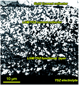 | ||
| Fig. 1 SEM image showing the microstructure of the screen-printed electrode over the YSZ electrolyte. Bright areas correspond to percolating LSM, while the darker ones correspond to YSZ. The image was acquired on a polished sample using low-energy incident electrons (Ee = 0.6 keV) and the in-lens secondary-electron detector. For the explanation of the contrast mechanisms see ref. 20. | ||
The as prepared porous cathode electrodes were optimized by means of catalyst impregnation. For this, known volumes of aqueous solutions of Ce, Mn or Pr nitrates were infiltrated under vacuum in order to obtain metal oxide loadings of about 1–2.5% in weight of the electrode. The impregnated cells were subsequently calcined at 750 °C for 30 minutes for the decomposition of the nitrate precursors. XRD analysis were also performed in samples of LSM/MOx from nitrates (50 wt%) in order to detect the formed oxides, confirming the formation of CeO2, Pr6O11 or Mn3O4, respectively. This is consistent with the existing literature.21–23 However, the valence state of Pr and Mn can change significantly during SOC operation.3
Microstructural and electrical characterization
Microstructural characterization of all the fabricated samples was performed by Field Emission-Scanning Electron Microscopy (FE-SEM) using a Carl Zeiss Merlin FE-SEM (Germany) equipped with Energy Dispersive Spectroscopy (EDS) (Oxford Instruments INCA-350 system, United Kingdom). The observation was performed on resin-infiltrated polished samples following the procedure described in ref. 24 and 25.Symmetrical cells were analysed by Electrochemical Impedance Spectroscopy (EIS) using a button-cell test rig (NorECs Probostat, Norway) and an electrochemical workstation (Zahner-Elektrik GmbH Zennium, Germany). EIS experiments were performed under air atmosphere at temperatures ranging from 850 °C down to 700 °C, and collecting data every 30 °C. The experiments were conducted at VDC = 0 V and using a sinusoidal signal amplitude of 20 mV. The frequency range was varied from 100 kHz to 100 mHz. The experimental EIS data was analyzed using distribution of relaxation times (DRT) to obtain the polarization resistances of each processes of the Voigt elements circuit of the cell. The analysis was performed using the Matlab script DRTtools.26
Single cell fabrication
Microtubular cell configuration was selected for this study. The supporting tubes were fabricated by powder extrusion moulding (PEM) following the procedure described in ref. 27. Subsequently, YSZ electrolytes and LSM/YSZ electrodes were deposited by dip-coating in a similar manner of those described in ref. 28. Standard Ni/YSZ–YSZ–LSM/YSZ microtubular cells were then infiltrated into the oxygen electrode side, following the procedure described Section 2.1.Electrochemical characterization of single cells
Electrochemical characterization of the microtubular cells was performed using an electrochemical workstation (Zahner-Elektrik GmbH Zennium, Germany). The cells were sealed using ceramic sealing (Aremco Ceramabond 522, USA). Gold wires were used as electrical contacts and gold paste (8880-G - ESL Electro-Science, USA) was used at the oxygen electrode side to improve current collection. Additional details for the experimental setup can be found in ref. 29 and 30.Results and discussion
Fabrication and electrical characterization of symmetrical cells
LSM/YSZ standard symmetrical cells were infiltrated with (Ce/Pr/Mn)Ox. The typical microstructure near the interface between the YSZ electrolyte and the LSM/YSZ electrode is shown in Fig. 2. For both samples, there is a homogeneous distribution of metal oxide nanoparticles up to the interface with the YSZ electrolyte, assuring an enhanced catalytic activity during fuel cell operation. As observed, the sizes of the nanocatalysers are typically ranging from 20 to 100 nm for both CeO2, Pr6O11 or MnOx samples.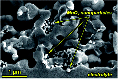 | ||
| Fig. 2 SEM image of manganese oxide infiltrated nanoparticles in the active region of the cathode. Secondary electron image of a fractured electrode–electrolyte interface (Ee = 5 keV). | ||
Typical Nyquist spectra for the three different analysed samples are shown in Fig. 3. The ohmic contribution was subtracted for clarification, and the obtained values were also divided by 2 to account for the symmetrical geometry of the half cells. The LSM/YSZ standard cell presented a polarization resistance of 0.39 Ω cm2 and 0.06 Ω cm2 at 700 °C and 850 °C, respectively. Although there are a wide range of values in the literature for this state-of-the-art cathode material (ranging from 0.03 Ω cm2 to 0.5 Ω cm2 at 850 °C) and its performance is very dependent on the microstructure, the present values are comparable with the best values reported.31,32 As observed in the figure, the polarization resistance of the CeO2 infiltrated sample is reduced in comparison with the standard LSM/YSZ cell. This improvement is about 15–18% at low temperatures (700–760 °C) and about 6–8% at high temperatures (790–850 °C). The effect of the infiltration of Pr6O11 nanoparticles into LSM/YSZ was more remarkable, since the polarization resistance of the cell was reduced to 0.068 Ω cm2 and 0.018 Ω cm2 at 700 °C (∼82% reduction) and 850 °C (∼70% reduction), respectively. The polarization resistance of the Pr-cell is very similar to the one previously reported for a Pr-infiltrated into a LSM/CGO backbone electrode. In addition, those results are among the lowest reported in the literature for a standard LSM/YSZ oxygen electrode.
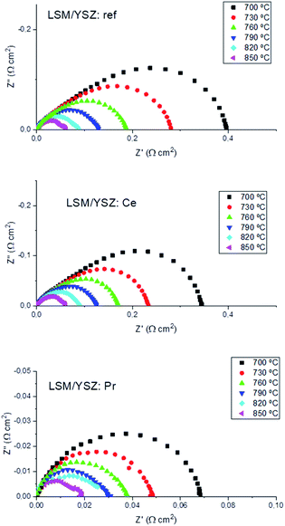 | ||
| Fig. 3 Impedance plots at different temperatures for standard, Ce-infiltrated and Pr-infiltrated LSM/YSZ symmetrical cells at different temperatures. | ||
EIS analysis using equivalent circuits and DRT
The asymmetric shape of impedance spectra clearly suggested the presence of several contributions to the overall polarization resistance which can be formally described by parallel combinations of R (resistance) and CPE (constant phase element) elements (so-called RQ-circuit). In addition, an inductance tail is always observed at high frequencies, which is mainly caused from the connecting wires of the setup system. It was found that the best fitting result with the minimum error gives an equivalent circuit where high- and medium-frequency processes are described by RQ circuits. For the high temperature spectra, a finite-length-Warburg impedance element (W) was added to account for the oxygen gas diffusion, as typically observed for well performing cathodes.28 As a consequence, the following equivalent circuit model was used:In order to verify the chosen equivalent circuit, we also analyzed the measurements by using the distribution of relaxation times (DRT) method. The different theoretical aspects of the DRT method are explained in detail in ref. 33–35. Following this procedure, we have used an adjustment function for discrepancy and cross-validation of the theoretical and experimental impedance data, and the optimal values of the discrepancy factor λ (comparative minimum between the discrepancy value and cross validation functions) were obtained for validation on the method.
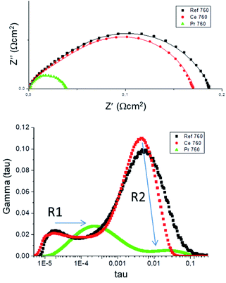
A summary of the fitted parameters is listed in Table 1. In addition, both equivalent circuit and DRT fittings are shown for the three studied cells at an intermediate temperature (760 °C) as an example in Fig. 4. As observed from both fittings, there is in general a good matching between both methods, as both resistances and peak frequencies do not differ significantly. As a consequence, the first conclusion is the validation of the selected equivalent circuit. However, it is also evident that the major discrepancy comes from the first RQ component, giving differences in the obtained R1 values. This is clearly a consequence of the inductance at higher frequencies, inducing some error in the equivalent circuit fitting as the first component is partially hindered by the inductance. If we observe the DRT analysis, the first peak is perfectly visible and thus, the fitting by this method is more reliable.
| Sample | Summary of the fitted parameters from equivalent circuit fitting (EC) and DRT method (DRT) | |||||||
|---|---|---|---|---|---|---|---|---|
| R 1 EC (Ω cm2), 700–2800 Hz | R 1 DRT (Ω cm2), 6 × 10⁴ to 105Hz | R 2 EC (Ω cm2) | R 2 DRT (Ω cm2) | R 3 EC (Ω cm2) | R 3 DRT (Ω cm2) | R pol EC (Ω cm2) | R pol DRT (Ω cm2) | |
| Ref – 700 °C | 0.10(1) | 0.05(1) | 0.33(1) | 0.37(7) | — | — | 0.43(2) | 0.42(8) |
| Ref – 730 °C | 0.077(4) | 0.032(6) | 0.23(1) | 0.25(3) | — | — | 0.31(1) | 0.28(4) |
| Ref – 760 °C | 0.055(3) | 0.023(4) | 0.155(4) | 0.17(2) | — | — | 0.21(1) | 0.19(2) |
| Ref – 790 °C | 0.038(2) | 0.015(8) | 0.111(3) | 0.11(2) | — | — | 0.15(1) | 0.13(3) |
| Ref – 820 °C | 0.047(9) | 0.012(7) | 0.045(7) | 0.06(1) | 0.008(1) | 0.015(3) | 0.10(2) | 0.09(2) |
| Ref – 850 °C | 0.037(8) | 0.010(6) | 0.025(6) | 0.04(1) | 0.010(1) | 0.007(2) | 0.07(1) | 0.06(2) |
| Ce – 700 °C | 0.113(7) | 0.05(1) | 0.265(9) | 0.29(2) | — | — | 0.38(2) | 0.33(3) |
| Ce – 730 °C | 0.079(2) | 0.035(5) | 0.179(6) | 0.19(1) | — | — | 0.26(1) | 0.23(2) |
| Ce – 760 °C | 0.061(4) | 0.025(6) | 0.131(4) | 0.14(1) | — | — | 0.19(1) | 0.17(2) |
| Ce – 790 °C | 0.044(3) | 0.024(4) | 0.091(4) | 0.10(1) | — | — | 0.14(1) | 0.12(1) |
| Ce – 820 °C | 0.035(4) | 0.020(4) | 0.067(5) | 0.06(1) | — | — | 0.10(1) | 0.08(1) |
| Ce – 850 °C | 0.041(6) | 0.015(4) | 0.024(5) | 0.04(1) | 0.005(1) | 0.005(2) | 0.065(5) | 0.055(5) |
| Pr – 700 °C | 0.048(3) | 0.063(6) | 0.026(3) | 0.006(1) | — | — | 0.074(6) | 0.069(7) |
| Pr – 730 °C | 0.040(3) | 0.043(5) | 0.014(3) | 0.004(1) | — | — | 0.054(6) | 0.047(6) |
| Pr – 760 °C | 0.035(2) | 0.034(5) | 0.007(3) | 0.004(1) | — | — | 0.037(5) | 0.037(6) |
| Pr – 790 °C | 0.028(1) | 0.026(3) | 0.007(2) | 0.004(1) | — | — | 0.035(3) | 0.031(4) |
| Pr – 820 °C | 0.035(2) | 0.019(3) | 0.009(5) | 0.004(2) | — | — | 0.036(7) | 0.024(5) |
| Pr – 850 °C | 0.010(1) | 0.010(2) | 0.010(9) | 0.004(1) | 0.004(1) | 0.004(2) | 0.024(2) | 0.019(5) |
As observed in Table 1, both R1 and R2 are activated with the temperature indicating that these two processes are related to the electrochemical activity of the oxygen electrode. Based on our previous analysis for LSM/YSZ standard cells,36 the first RQ component presented capacitance values ranging from 2.2 × 10⁻³ to 7.8 × 10⁻⁴ F cm−2 and summit frequencies ranging from 6 to 10 kHz, and it was tentatively associated to YSZ ionic transport from the triple phase boundary (TPB) to the interface with the electrolyte (charge transfer process). The second RQ component showing capacitance values in the range of 1.4 × 10⁻² to 2.2 × 10⁻² F cm−2 and summit frequencies of 30–1500 Hz, was ascribed to dissociative adsorption of oxygen and surface diffusion of oxygen species, which are typically coupled. Finally, the third component W3, only visible above 800 °C, with capacitance values in the range of 5 F cm−2 and summit frequencies of 1–2 Hz, was associated to gas diffusion and conversion. This type of diffusion process is not activated thermally, in concordance with other studies in the literature.37
It is clearly observed from Table 1, that although both R1 and R2 components are reduced when increasing the temperature, the reduction of R2 is much noticeable. The same effect was observed when metal oxides are infiltrated, as the polarization resistance reduction is mainly observed for the R2 component. This finding suggests that metal oxide infiltration mainly enhances oxygen dissociation and surface diffusion processes in comparison with the charge transfer and/or oxygen ion migration process enhancement. These findings are consistent with that of Klemensø et al.,38 where a significant improvement in the performance of LSM–YSZ electrodes by CGO infiltration is reported. These authors suggest that oxygen deficiency of the CeO2 structure of cerium oxide is favorable for the oxygen absorption/dissociation on the electrode surface, as appropriate sites are created. In addition, a diffusion enhancement of oxygen ions was reported when CeO2 or CGO is infiltrated.39
As for the Pr infiltrated-sample, it presents an extraordinary enhancement in terms of polarization resistance reduction. This is consistent with the studies of Navarrete et al.,17 where they observed the best performance for a Pr-infiltrated LSM/CGO electrode. We believe that the mixed electronic and ionic conduction of Pr6O11 is responsible of this significant enhancement, creating additional oxygen ion diffusion pathways to increase the oxygen surface exchange parameters, and thus improving the oxygen evolution reaction (OER). This is also consistent with the major decrease of R2, in comparison with the R1 contribution, which is only dependent on the ionic conductivity of the electrode.
Optimization of the infiltration process
Finally, the amount of infiltrated metal oxide nanoparticles was optimized for the case of the CeO2 sample. Samples with 1 wt%, 1.6 wt% and 2 wt% of infiltrated CeO2 were fabricated. The obtained polarization resistances are summarized in Table 2, showing a decrease on the polarization resistance of the cells with increasing the amount of CeO2 nanoparticle infiltration and reaching a maximum for 2 wt% of infiltrated CeO2. Further amount of nanoparticle infiltration above 2.5 wt% is not beneficial, as metal nanoparticles block oxygen diffusion through the electrode, increasing concentration polarization.| Temp. (°C) | Ref. | 1 wt% CeO2 | 1.6 wt% CeO2 | 2 wt% CeO2 | |||
|---|---|---|---|---|---|---|---|
| R pol (Ω cm2) | R pol (Ω cm2) | Decrease (%) | R pol (Ω cm2) | Decrease (%) | R pol (Ω cm2) | Decrease (%) | |
| 700 | 0.39 | 0.33 | 15 | 0.28 | 28 | 0.14 | 64 |
| 730 | 0.28 | 0.23 | 18 | 0.18 | 36 | 0.09 | 68 |
| 760 | 0.19 | 0.16 | 16 | 0.13 | 32 | 0.06 | 68 |
| 790 | 0.13 | 0.12 | 8 | 0.09 | 31 | 0.05 | 61 |
| 820 | 0.09 | 0.085 | 6 | 0.06 | 33 | 0.03 | 67 |
| 850 | 0.06 | 0.055 | 8 | 0.04 | 33 | 0.02 | 67 |
In addition, we have performed symmetrical cell analysis in another batch of cells in order to validate the use of MnOx nanoparticles into LSM/YSZ electrodes, in comparison with the well-studied Ce infiltrated samples. For example, we have measured a polarization resistance of 0.210 Ω cm2, 0.172 Ω cm2 and 0.175 Ω cm2 at 850 °C, for a reference cell, Ce-infiltrated cell and Mn-infiltrated cell, respectively. In this case, the improvement of the Ce-cell is about 18%, very similar of the one of the Mn cell (about 17%), which is also consistent with the results analyzed above. Unfortunately, the data is not quantitatively comparable with the previous Pr and Ce oxide samples, as the thicknesses of the electrode of these samples are significantly lower (∼10 μm). In any case, this result validates the use of cerium, manganese or praseodymium oxides as nanocatalysers for boosting the performance of SOC cells.
Electrochemical characterization of microtubular cells
Based on the superior performance obtained in symmetrical cells for Pr-oxide infiltration into LSM/YSZ oxygen electrodes, the effect of oxide infiltration is also studied in complete microtubular cells. These studies will be completed with Mn oxide infiltration, as there is very little information for the infiltration of these two metal oxides in the literature. The electrochemical performance in SOFC mode of a 2.5 wt% Pr6O11 infiltrated cell is shown in Fig. 5 (current density vs. voltage curves). The experiment was performed at temperatures between 600 and 800 °C. The results are also compared with a standard Ni/YSZ–YSZ–LSM/YSZ cell fabricated in our laboratory, using the same fabrication process and composition as previously reported.25,27 For example, current densities of about −1.3 A cm−2 were measured at 800 °C and 0.7 V, improving the performance of other oxygen electrodes using the same microtubular Ni/YSZ–YSZ cells (−0.97 A cm−2 for LSCF,26 −0.85 A cm−2 for Pr2NiO4+δ,40 or −1 A cm−2 for LSM infiltrated into YSZ41). It is also very remarkable that, as observed in Fig. 5, the Pr-infiltrated cell presents about the same electrochemical performance at 700 °C, in comparison with an standard cell at 800 °C. This significant decrease of the operation temperature maintaining the electrochemical performance will be beneficial for the long-term operation of microtubular SOC systems.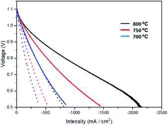 | ||
| Fig. 5 Comparison between a standard non impregnated cell (dotted line) and a cell impregnated with 2.5 wt% Pr6O11 (continuous thick line) at temperatures of 700 °C, 750 °C and 800 °C. | ||
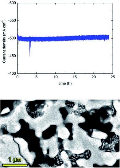
In order to study the stability of the Pr-infiltrated electrode, a chronoamperometry experiment was performed at 700 °C and 0.7 V for 24 hours. As observed in Fig. 6, the measured current density remains stable at a value of about −500 mA cm−2. SEM analysis before and after the electrochemical experiments confirmed that there is a slight growth of Pr6O11 particles. In any case, this growth is no affecting the electrochemical performance, at least up to a period of about 100 hours at maximum temperatures of 800 °C. In any case, longer term experiments are desired in order to validate the stability of these type of cells.
In addition, a Mn-infiltrated cell was also fabricated and electrochemically tested in both fuel cell and electrolysis modes. For this purpose, a fuel mixture of 50% H2–50% H2O was used in the fuel electrode side and synthetic air was used in the oxygen electrode side. As observed in Fig. 6, current densities of about −700 mA cm−2 were measured at 800 °C and 0.7 V, improving the performance in comparison with a standard cell (see Fig. 5). This enhancement is even more remarkable in electrolysis mode, where current densities above 1 A cm−2 were obtained at 800 °C at the thermoneutral voltage (1.3 V). To the best of our knowledge, this result is the highest reported for microtubular YSZ based cells, outperforming previous cells in SOEC mode. For example, using Ni–YSZ/YSZ with different oxygen electrodes at the same SOEC conditions, current densities of 780 mA cm−2 (LSM infiltrated into porous YSZ),6 845 mA cm−2 (LSCF-CGO)26 and 900 mA cm−2 (PNO-CGO)42 were measured.
Finally, in order to compare the effect of both Pr and Mn oxides infiltration, also in comparison with a reference cell, EIS experiments were conducted and analyzed at OCV conditions and also under anodic polarization (SOFC: +400 mA cm−2). Fig. 8 shows the typical Nyquist plots (left) and the DRT analysis (right) for the three microtubular samples at both OCV and under anodic polarization. From the Nyquist plots, a clear reduction of the polarization resistance was observed when introducing metallic oxide nanoparticles into the LSM–YSZ electrodes, being more noticeable for the case of Pr, which is also consistent with the j–V measurements already shown in Fig. 5 and 7. As for the DRT analysis, best fitting was obtained using four components, named R1–R4. Based on previous studies on similar cells,31 the different components were assigned as follows: R1 was attributed to charge transfer mechanism at the oxygen electrode, R2 was attributed to fuel electrode activation, R3 was attributed to oxygen electrode activation, and R4, to fuel electrode diffusion. Although a detailed analysis is complex, the DRT analysis is consistent with the proposed assignation, as R1 and R3 are the components with more significant reduction when introducing Pr or Mn oxide nanoparticles (both assigned to the oxygen electrode), whereas R2 and especially R4 remains about constant, both assigned to the fuel electrode. The reason why some difference can be observed in the fitting of R2 could be attributed with partial overlapping with both R1 and R3 components.
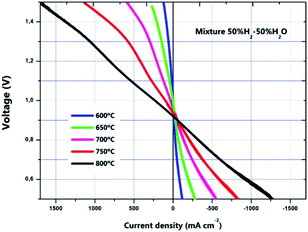 | ||
| Fig. 7 Current density (j) versus voltage (V) in both fuel cell and electrolysis mode performed at temperatures between 600 and 800 °C for the manganese infiltrated cell. | ||
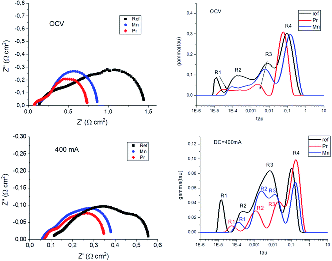 | ||
| Fig. 8 Nyquist plots (left) and DRT analysis (right) performed under OCV conditions and under DC = 400 mA cm−2 (SOFC mode). | ||
Conclusions
Infiltration of Ce, Pr or Mn oxide nanoparticles was found to increase significantly the performance of SOC cells using standard LSM/YSZ oxygen electrodes. In particular, it was found that infiltration of PrOx nanoparticles was more effective, as polarization resistances of 0.068 Ω cm2 and 0.018 Ω cm2 at 700 °C and 850 °C were obtained, being the lowest for any LSM/YSZ based oxygen electrode reported in the literature. In addition, the electrochemical performance in SOFC mode of a 2.5 wt% Pr-cell showed current densities of about −1.3 A cm−2 at 800 °C and 0.7 V, outperforming the performance of other microtubular YSZ cells. In addition, a manganese oxide-infiltrated cell was also fabricated and electrochemically tested in both fuel cell and electrolysis modes. In this case, the enhancement is more remarkable in electrolysis mode, where current densities above 1 A cm−2 were obtained at 800 °C at the thermoneutral voltage (1.3 V). Pr and Mn oxides are confirmed as excellent candidates for boosting the performance of standard SOC electrodes.Author contributions
A. O. and M. A. L. B. conceived the idea and designed the experiments. A. B. and J. S. carried out the preparation of the samples and performed the experimental analysis. A. L. performed the SEM experimental measurements and analysis. M. A. L. B. and A. B. performed the electrochemical measurements. A. B., J. S., A. L., A. O. and M. A. L. B. analysed the data and wrote the manuscript. All authors have read and agreed to the published version of the manuscript.Conflicts of interest
There are no conflicts to declare.Acknowledgements
This paper is written in honour of Prof. John Kilner's 75th birthday. It is a pleasure to contribute on this special issue to tribute his distinguish career. His work (and not only his work) has been an inspiration for us and still will be for many young researchers in the field of solid state energy materials and devices. This research has received funding from grants PID2019-107106RB-C32 funded by MCIN/AEI/10.13039/501100011033 and RTI2018-098944-J-I00 funded by MCIN/AEI/10.13039/501100011033 and by “ERDF A way of making Europe”. A. O. also acknowledges financial support from the Ramón y Cajal program (RYC2018-025553-I) funded by MCIN/AEI/10.13039/501100011033 and by “ESF Investing in your future”. Furthermore, the use of Servicio General de Apoyo a la Investigación (SAI, University of Zaragoza) is also acknowledged.References
- R. M. Ormerod, Chem. Soc. Rev., 2003, 32, 17–28 RSC.
- J. Peng, J. Huang, X. Wu, Y. Xu, H. Chen and X. Li, J. Power Sources, 2021, 505, 230058 CrossRef CAS.
- D. Ding, X. Li, S. Y. Lai, K. Gerdes and M. Liu, Energy Environ. Sci., 2014, 7, 552–575 RSC.
- T. Z. Sholklapper, C. P. Jacobson, S. J. Visco and L. C. De Jonghe, Fuel Cells, 2008, 8, 303–312 CrossRef CAS.
- S. P. Jiang, Int. J. Hydrogen Energy, 2012, 37, 449–470 CrossRef CAS.
- A. R. Hanifi, M. A. Laguna-Bercero, T. H. Etsell and P. Sarkar, Int. J. Hydrogen Energy, 2014, 39, 8002–8008 CrossRef CAS.
- T. Wu, B. Yu, W. Zhang, J. Chen and S. Zhao, RSC Adv., 2016, 6, 68379–68387 RSC.
- P. A. Connor, X. Yue, C. D. Savaniu, R. Price, G. Triantafyllou, M. Cassidy, G. Kerherve, D. J. Payne, R. C. Maher, L. F. Cohen, R. I. Tomov, B. A. Glowacki, R. V. Kumar and J. T. S. Irvine, Adv. Energy Mater., 2018, 8, 1800120 CrossRef.
- R.-T. Wang, H.-Y. Chang and J.-C. Wang, Polymers, 2021, 13, 2774 CrossRef CAS PubMed.
- Z. Jiang, C. Xia and F. Chen, Electrochim. Acta, 2010, 55, 3595–3605 CrossRef CAS.
- Y. Y. Ren, J. T. Ma, D. S. Ai, Q. F. Zan, X. P. Lin and C. S. Deng, J. Mater. Chem., 2012, 22, 25042–25049 RSC.
- N. Imanishi, R. Ohno, K. Murata, A. Hirano, Y. Takeda, O. Yamamoto and K. Yamahara, Fuel Cells, 2009, 9, 215–221 CrossRef CAS.
- Q. S. Zhang, A. Hirano, T. Matsumura, N. Imanishi, Y. Takeda and K. Yamahara, J. Fuel Cell Sci. Technol., 2009, 6, 011010–011014 CrossRef.
- F. L. Liang, J. Chen, S. P. Jiang, F. Z. Wang, B. Chi, J. Pu and L. Jian, Fuel Cells, 2009, 9, 636–642 CrossRef CAS.
- S.-L. Zhang, H. Wang, M. Y. Lu, C.-X. Li, C.-J. Li and S. A. Barnett, J. Power Sources, 2019, 426, 233–241 CrossRef CAS.
- M. A. Laguna-Bercero, R. Campana, A. Larrea, J. A. Kilner and V. M. Orera, J. Power Sources, 2011, 196, 8942–8947 CrossRef CAS.
- L. Navarrete, C. Solís and J. M. Serra, J. Mater. Chem. A, 2015, 3, 16440–16444 RSC.
- C. Nicollet, A. Flura, V. Vibhu, A. Rougier, J. M. Bassat and J. C. Grenier, Int. J. Hydrogen Energy, 2016, 41, 15538–15544 CrossRef CAS.
- Y. Wang, T. Su, A. D. Brocato and X.-D. Zhou, ECS Trans., 2019, 91, 1527–1533 CrossRef CAS.
- K. Thyden, Y.-L. Liu and J. Bilde-Sørensen, Solid State Ionics, 2008, 178, 1984–1989 CrossRef CAS.
- N. Imanishi, R. Ohno, K. Murata, A. Hirano, Y. Takeda, O. Yamamoto and K. Yamahara, Fuel Cells, 2009, 9, 215–221 CrossRef CAS.
- C. Nicollet, A. Flura, V. Vibhu, A. Rougier, J.-M. Bassat and J. C. Grenier, Int. J. Hydrogen Energy, 2016, 41, 15538–15544 CrossRef CAS.
- B. Serensen, S. Gaal, M. Tangstad, E. Ringdalen, R. Kononov and O. Ostrovski, Proceedings of the Twelfth International Ferroalloys Congress Sustainable Future, 2010, vol. 1, pp. 439–448 Search PubMed.
- R. Campana, A. Larrea, J. I. Peña and V. M. Orera, J. Eur. Ceram. Soc., 2009, 29, 85–90 CrossRef CAS.
- S. Serrano-Zabaleta, M. A. Laguna-Bercero, L. Ortega-San-Martin and A. Larrea, J. Eur. Ceram. Soc., 2014, 34, 2123–2132 CrossRef CAS.
- T. H. Wan, M. Saccoccio, C. Chen and F. Ciucci, Electrochim. Acta, 2015, 184, 483–499 CrossRef CAS.
- B. I. Arias, M. E. Sotomayor, A. Várez, B. Levenfeld, H. Monzón, M. A. Laguna-Bercero and A. Larrea, RSC Adv., 2016, 6, 19007–19015 RSC.
- H. Monzón, M. A. Laguna-Bercero, A. Larrea, B. I. Arias, A. Várez and B. Levenfeld, Int. J. Hydrogen Energy, 2014, 39, 5470–5476 CrossRef.
- M. J. López-Robledo, M. A. Laguna-Bercero, A. Larrea and V. M. Orera, J. Power Sources, 2018, 378, 184–189 CrossRef.
- H. Monzón and M. A. Laguna-Bercero, Electrochim. Acta, 2016, 222, 1622–1627 CrossRef.
- J. Nielsen and J. Hjelm, Electrochim. Acta, 2014, 115, 31–45 CrossRef CAS.
- W. H. Kan, A. J. Samson and V. Thangadurai, J. Mater. Chem. A, 2016, 4, 17913–17932 RSC.
- M. Saccoccio, T. H. Wan, C. Chen and F. Ciucci, Electrochim. Acta, 2014, 147, 470–482 CrossRef CAS.
- F. Ciucci and C. Chen, Electrochim. Acta, 2015, 167, 439–454 CrossRef CAS.
- A. L. Gavrilyuk, D. A. Osinkin and D. I. Bronin, Russ. J. Electrochem., 2017, 53, 575–588 CrossRef CAS.
- J. A. Cebollero, R. Lahoz, M. A. Laguna-Bercero and A. Larrea, J. Power Sources, 2017, 360, 336–344 CrossRef CAS.
- E. P. Murray, T. Tsai and S. A. Barnett, Solid State Ionics, 1998, 110, 235–243 CrossRef CAS.
- T. Klemensø, C. Chatzichristodoulou, J. Nielsen, F. Bozza, K. Thyden, R. Kiebach and S. Ramousse, Solid State Ionics, 2012, 224, 21–31 CrossRef.
- N. Ai, K. Chen and S. P. Jiang, Solid State Ionics, 2013, 233, 87–94 CrossRef CAS.
- M. A. Laguna-Bercero, H. Monzón, A. Larrea and V. M. Orera, J. Mater. Chem. A, 2016, 4, 1446–1453 RSC.
- M. A. Laguna-Bercero, A. R. Hanifi, T. H. Etsell, P. Sarkar and V. M. Orera, Int. J. Hydrogen Energy, 2014, 40, 5469–5474 CrossRef.
- M. A. Morales-Zapata, A. Larrea and M. A. Laguna-Bercero, Int. J. Hydrogen Energy, 2020, 45, 5535–5542 CrossRef CAS.
| This journal is © The Royal Society of Chemistry 2022 |


