A flexible and stretchable triboelectric nanogenerator based on a medical conductive hydrogel for biomechanical energy harvesting and electronic switches†
Junwei
Zhao
 *a,
Yujiang
Wang
a,
Bo
Wang
a,
Yuetan
Sun
a,
Haoqiang
Lv
a,
Zijian
Wang
a,
Wenqing
Zhang
a and
Yongdong
Jiang
*ab
aHenan Key Laboratory of Special Protective Materials, Materials Science and Engineering School, Luoyang Institute of Science and Technology, Luoyang, 471023, P. R. China. E-mail: jwzhao2010@lit.edu.cn
bTsinghua Innovation Center in Dongguan, Dongguan, 523808, P. R. China. E-mail: jiangyd@tsinghua-dg.org
First published on 2nd March 2023
Abstract
With the development of intelligent wearable electronic products, new requirements are put forward for large-scale production and durable power supplies and sensors. Herein, a flexible and stretchable single-electrode triboelectric nanogenerator (TENG) based on a medical conductive hydrogel (MCH) has been fabricated for biomechanical energy harvesting and electronic switches. The obtained MCH-TENG encapsulated by silicone rubber as an electrification layer demonstrated high electrical output performances. The size of the fabricated MCH-TENG was 40 × 60 mm2, which can generate an open-circuit voltage of 400 V, a power density of 444.44 mW m−2, and power 240 LEDs in series at a contact frequency of 3.0 Hz. The device can act not only as a power supply to drive electronic devices, but also as an energy collector to collect the energy of human movements. Particularly, as an electronic switch, the device enabled a high current amplification through the Darlington transistor circuit. Consequently, this work provides a new perspective of flexible and stretchable MCH-TENGs for wearable electronic devices.
1. Introduction
In the past decade, wearable electronic devices have been developed vigorously due to their wide application in human motion energy harvesting,1–4 motion tracking,5,6 human–machine interactions,7–9 and so on. At present, most portable electronic devices require a continuous external power supply. However, these devices now rely mainly on chemical batteries, which need to be frequently recharged or replaced. This potentially causes severe environmental pollution and consumes many resources.10–13 In addition, most of the current power supplies cannot meet the requirements of biocompatibility, flexibility, stretchability, and ease of mass production of wearable electronic products.14 Therefore, the research and development of high scalability and compatible energy harvesting devices is still a challenge.14–16A triboelectric nanogenerator (TENG) is considered as an effective tool to convert low-frequency mechanical energy into electrical energy based on the coupling effect of contact electrification and electrostatic induction.4,17–25 TENGs can effectively harvest many types of low-frequency mechanical energy including human daily activities, wind energy, ocean energy26–28 for energy conversion, self-powered sensors, physiological monitoring,4,29–32 and human–machine interactions.9,33,34 In order to realize biomechanical energy harvesting and physiological sensing, a wearable TENG requires the features of flexibility, comfortability, and stretchability of both the triboelectric layer and the electrode layer. In view of this, many soft materials have been explored for flexible TENG preparation, such as polymer nanofibers,35 commercial fabrics,36 paper,37 foam materials,38etc. A conductive hydrogel, a flexible hydrophilic polymer with a three-dimensional cross-linked network, is an ideal stretchable conductor material for TENG flexible electrodes.2,3,39 Conductive hydrogels have the characteristics of adjustable physical/chemical properties, excellent electrical conductivity, high flexibility, self-healing ability, and good biocompatibility.40–42 Therefore, in recent years, hydrogels have received great attention in the development of flexible and portable TENGs. Hydrogel-based TENGs have broad application prospects in many fields, such as flexible sensing, biomechanical energy collection, and biomedical devices.43–46 However, in previous works, most of the hydrogels used to prepare TENGs were synthesized in laboratories. Many of the results are just proof of concept. Compared with the conductive hydrogels synthesized in laboratories, commercial conductive hydrogels have the advantages of biocompatibility, low cost, and scalability.
Herein, a flexible and stretchable TENG based on a commercial medical conductive hydrogel (short for MCH-TENG) as an electrode has been developed for biomechanical energy harvesting and electronic switches. The selected MCH has been employed for diagnosis, monitoring or filling and coating between skin and electrodes during medical treatment and can form a relatively stable conductive connection between skin and electrodes. The MCH as a water-based polymer gel mainly contains a biocompatible and stable electrolyte, which provides high conductivity, extensibility and shape adaptability to act as the electrode of TENGs. The silicone rubber that encapsulates the MCH serves as both a protective layer and a friction layer. The fabricated MCH-TENG had an effective electrode area of 60 × 40 mm2, which can generate an open circuit voltage (Voc) of 400 V, a short-circuit current density (Jsc) of 1.2 mA m−2, and a transferred short-circuit charge density (σsc) of 53 μC m−2 at a contact frequency of 3.0 Hz. Therefore, the MCH-TENG can be used for biomechanical energy harvesting, as a power supply for small electronic devices and an electronic switch combined with a Darlington transistor. The prepared MCH-TENG with excellent energy collection and high output has promising application in wearable electronic devices and human–machine interactions and demonstrates the mass production potential of wearable electronic devices.
2. Results and discussion
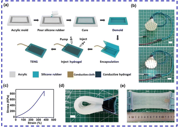
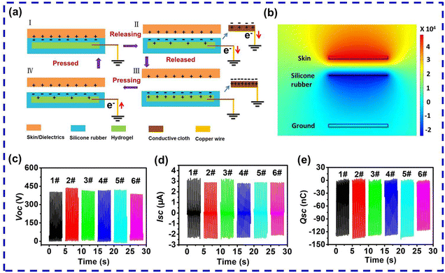
Fig. 1a shows the preparation process of the flexible and stretchable MCH-TENG. The work mode of the prepared MCH-TENG was single electrode mode. Silicone rubber was selected as the coating layer and friction layer because of its high electronegativity, good flexibility and stretchability.3,4,20 In our case, the thickness of the silicone rubber as the friction layer was about 0.5 mm and the thickness of the prepared MCH-TENG was about 3.5 mm unless otherwise specified. Upon contact with human skin, the silicone rubber surface generates a large number of negative triboelectric charges, and the human skin surface produces a large number of positive triboelectric charges, which depends on the electronegativity of the two friction materials.47,48 The MCH is composed of propylene glycol, sodium chloride, glycerin, sodium cocoyl amphoteric acetate, silicone oil, lemon essence, water, etc. At room temperature the conductivity of the MCH is 10.0–85.0 mS cm−1, which is much higher than that of the ionic conductive hydrogel (2.2 mS cm−1) reported previously.2 As shown in Fig. 1b, a light-emitting diode (LED) lamp was lit up when the MCH strip was connected to the circuit, which confirmed that the MCH had a good conductivity. Moreover, the MCH is a jelly-like gel with certain fluidity. In a previous work, the device with a thickness of 4.0 mm using silicone rubber as the coating layer can withstand a tensile strain of 412%.20 In our case, the tensile property of the silicone rubber cube (59 × 10 × 2 mm3) was evaluated by the uniaxial tensile test. The silicone rubber cube ruptured at a stress of 890 kPa and reached the maximum tensile strain of 375% (Fig. 1c). Therefore, the obtained TENG based on the silicone rubber and MCH electrode can withstand large deformation when attached to the human body. Fig. 1d and e show the photographs of the MCH-TENG in different deformation states. The MCH-TENG can be bent and stretched, implying its good tensile properties, shape adaptability, and ability to collect mechanical energy under various human movements.The working mechanism of the MCH-TENG is based on the synergistic effects of triboelectrification and electrostatic induction (Fig. 2a). Human skin or positive triboelectric materials were used as matching materials. A previous work has reported a sequence of triboelectric materials, and the ability of the materials to acquire and lose electrons is closely related to their polarity.47 When human skin comes into contact with silicone rubber, the human skin easily loses electrons and exhibits positive charges on the surface, while the silicone rubber easily gains electrons and exhibits negative charges on its surface. Since the number of electrons obtained and lost is equal, the skin and the silicone rubber are in electrostatic equilibrium at this stage (Fig. 2a-I). With the gradual separation of the skin and the silicone rubber, some positive ions are induced at the interface between the MCH electrode and the silicone rubber, and the negative ions on the other side of the electrode drive the transient charge to the ground along the external circuit to generate an electrical signal (Fig. 2a-II). When the distance between the skin and the silicone rubber is far enough, the frictional and induced charges form an electrostatic equilibrium, at which there is no electrical signal in the circuit (Fig. 2a-III). When the skin reversely approaches the silicone rubber, the working mechanism is reversed. In this process, the electrons flow back from the ground through an external circuit to the MCH electrode (Fig. 2a-IV). Therefore, an alternating signal is generated during the reciprocating contact and separation between the skin and the MCH-TENG. In the process, the positive ions (sodium ions) and negative ions (chloride ions) in the MCH electrode play an important role in the electrical output of the MCH-TENG. The interface between the MCH electrode and the silicone rubber forms another friction electrification layer, which is conducive to charge transfer.49,50 To further understand the working mechanism of the MCH-TENG, the corresponding potential distribution in the process of contact and separation was simulated by the COMSOL software (Fig. 2b). It can be seen from the simulated potential distribution that there is an obvious potential difference between the positive and the negative triboelectric layers, which leads to the generation of induced charges.
To verify the conductivity of the MCH electrode, a copper wire and conductive cloth with different areas (labeled as sample 1#–6#) were selected as external electrodes to examine the influence of a hybrid electrode pair composed of the MCH and an external electrode on the output performance of the MCH-TENG. A copper wire was used as the conductor of the 1# MCH-TENG. For the 2#–6# MCH-TENGs, the areas of the conductive clothes were 10 × 10, 10 × 60, 20 × 60, 30 × 60, and 40 × 60 mm2, respectively. The optical photograph of the 1#–6# MCH-TENGs stored for two months is shown in Fig. S1.† It should be noted that the conductive cloths were wrapped in the MCH and did not contact the silicone rubber. Therefore, no triboelectrification occurred between the conductive cloth and the silicone rubber. The output performance of the MCH-TENGs with hybrid electrodes was studied with defatted cowhide as the positive triboelectric material to contact with the MCH-TENG at a frequency of 3.0 Hz. The Voc, Isc and transferred charges (Qsc) of the 1#–6# MCH-TENGs with hybrid electrodes are shown in Fig. 2c–e. The electrical output performance of the six samples was almost the same. These results demonstrated that the external electrode had little effect on the output performance of the MCH-TENGs, and the conductivity of the samples mainly depended on the MCH electrode. It was noticed that the copper wire in the 1# MCH-TENG was gradually oxidized after two months. However, the samples with conductive cloths as the outer electrodes remained stable, indicating that the conductive cloth plated with copper and nickel exhibited good stability and corrosion resistance. Therefore, taking the cost into account, the 2# MCH-TENG was employed as the representative sample for further performance research.
The electrical output performance of the 2# MCH-TENG at different contact frequencies (0.5–3.0 Hz) was investigated systematically. Human daily activities and exercise habits are usually observed in this frequency range. As can be seen in Fig. 3a–c, as the contact frequency increased from 0.5 to 3.0 Hz, Voc remained at 400 V, and σsc remained at 53 μC m−2, revealing that the change of frequency had no effect on Voc and σsc. In a previous work, the generated σsc value of the S-TENG prepared by silicone rubber coated conductive cloth was 45 μC m−2,4 which was about 16% lower than that of this report. In contrast, when the frequency increased from 0.5 to 3.0 Hz, the Jsc increased from 0.2 to 1.2 mA m−2 due to the variation of the MCH-TENG deformation rate.3,4 In practical applications, external loads may affect the output performance of energy harvesting devices. Therefore, the output voltage of the 2# MCH-TENG with different loads was then evaluated. With the increase of the resistance of the external load, the voltage of the external load experienced a slow increase at first, then a sharp increase, and finally a slow increase again (Fig. S2†). When the contact frequency was fixed, the output power density first gradually increased with the increase of the load resistance, reached the peak (Pmax), and then gradually decreased (Fig. 3d). Moreover, in the frequency range of 0.5–3.0 Hz, the calculated Pmax value of the 2# MCH-TENG with different loads was 25.52, 133.47, 187.71, 255.21 and 444.44 mW m−2, respectively. Under the same test conditions, the Pmax value (444.44 mW m−2) of the MCH-TENG in this study was much higher than that (222.57 mW m−2) of the S-TENG prepared by silicone rubber coated conductive cloth reported in our previous work,4 showing the superior performance of the MCH-TENG. The possible mechanism of this enhancement effect could be due to the formation of another triboelectric layer at the interface between the MCH and the silicone rubber layer. The results in Fig. 7a prove the existence of this triboelectric layer. Similar phenomena have been reported in previous works.46,51,52 According to a previous report, Pmax and the optimal matching load resistance are dependent on the contact frequency.53 The trend of Pmax and the inherent impedance of the 2# MCH-TENG matching with the load resistance was consistent with the theoretical prediction.53 When the strike frequency increased from 0.5 to 3.0 Hz, the inherent impedance of the 2# MCH-TENG decreased from 500 to 150 MΩ.
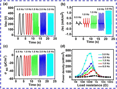 | ||
| Fig. 3 Electrical output performance of the 2# MCH-TENG at different contact frequencies. (a–c) Electrical output (Voc, Jsc and σsc). (d) Power densities under different external loads. | ||
Due to the fluidity of the MCH and the high flexibility, toughness and stretchability of the silicone rubber, the MCH-TENG can maintain its function even when experiencing large deformation. The electrical performance of the 2# MCH-TENG was investigated at various stretching strain levels. The corresponding electrical output performance is shown in Fig. 4. With the increase of tensile strain from 0% to 50%, the Voc, Isc and Qsc values all increased. The changes in the contact area, thickness of the dielectric layer and the relevant resistance of the device during stretching had a synergistic effect on the output behavior.54,55 According to the Poisson effect,56,57 with the increase of tensile strain of the 2# MCH-TENG, the device became longer and longer, which changed the contact area of the device, and the silicone rubber became thinner and thinner, which shortened the distance between the surface charge of the silicone rubber and the MCH electrode. Considering the theoretical model in the previous work,53,58 the contact area of the device and the thickness of the dielectric layer both affect the electrical output performance. In our case, the tensile strain did not exceed 50%. Therefore, during the process of stretching, the contact area was always increasing and the silicone rubber became thinner. As a result, the Voc, Isc and Qsc values were increasing. In a previous report, the human arm skin can endure a maximum strain of about 27%.59 Therefore, the obtained MCH-TENG system can perform desirable function under common skin physical conditions.
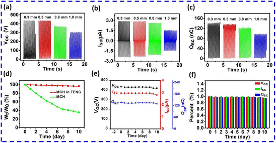
Previous reports have shown that the thickness of the triboelectric layer affects the output performance of the devices.60–62 In this study, to investigate the influence of the thickness of the silicone rubber triboelectric layer on the output performance of the devices, we prepared four MCH-TENGs with the silicone rubber thickness of 0.3, 0.5, 0.8 and 1.0 mm, respectively. The device outputs are shown in Fig. 5a–c. When the thickness of the silicone rubber layer is less than 0.5 mm, the output performance of the devices decreases slightly with increasing the silicone rubber thickness. When the silicone rubber layer exceeds 0.5 mm, the output performance of the device becomes weaker and weaker with the increase of the silicon rubber thickness. The Voc, Isc and Qsc values decrease from 441 V, 2.9 μA and 143 nC at 0.3 mm thickness to 302 V, 1.5 μA, and 97 nC at 1.0 mm thickness. Increasing the thickness of the triboelectric layer weakens the electrostatic induction between it and the MCH electrode, which is not conducive to increasing the output performance of the device. Therefore, for practical applications, the thickness of the triboelectric layer shall be optimized to balance the mechanical and electrical properties of the devices.
With the rapid development of electronic devices based on hydrogels, the dehydration of hydrogels has become a key problem in this field, which affects the service life of devices. We carried out dehydration tests for the uncoated MCH and the MCH in the MCH-TENG at room temperature for 10 days. Meanwhile, the output performance of the device with a silicon rubber layer of 0.5 mm was monitored. As shown in Fig. 5d, the weight of the uncoated MCH decreases with the increase of time and maintains 35.34% of its initial weight after 10 days, indicating that the water content was lost significantly. In contrast, the weight retention ratio of the MCH in the MCH-TENG is 96.16% after 10 days. These results indicate that silicone rubber coating is beneficial for preventing the water loss of the hydrogel. In the previous work, the PDMS coated hydrogel maintained 72.4% of its original weight after 3 days.63 The electrical properties of the MCH-TENG were tested daily for 10 days corresponding to the water retention data. As shown in Fig. 5e and f, the MCH-TENG can maintain its original output performance without significant degradation when the hydrogel was packaged with the Ecoflex silicon rubber for 10 days. The outputs of Voc, Isc and Qsc maintain above 94% of their original values. In previous reports, the output performance of the SA–Zn hydrogel TENG remained at 85% after 3 days.46 This clearly shows that the MCH-TENG prepared by direct encapsulation of the MCH has excellent stability.
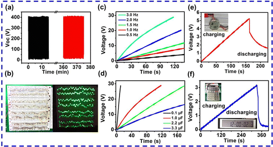
In view of its excellent electrical output, the MCH-TENG was further explored as a power supply for portable electronic devices. First, the output stability of the 2# MCH-TENG was studied. Voc remained almost constant for 375 minutes of continuous contact-separation cycles (1.0 Hz), indicating that the flexible MCH-TENG had significant robustness and was suitable for practical applications (Fig. 6a). Subsequently, the MCH-TENG was used as the power supply of LEDs. In order to prove that the 2# MCH-TENG can provide sustainable energy for external loads, 240 green LEDs in series were connected to the 2# MCH-TENG. These LEDs were lit up when the 2# MCH-TENG was operated at a contact frequency of 3.0 Hz (Fig. 6b and Movie S1†). Furthermore, as a stable power supplier of portable electronic products, the TENG needs an electrical management circuit to convert the AC output to the DC output. A rectifier equivalent circuit for the charge and discharge of small electronic equipment is shown in Fig. S3.† The components of the rectifier circuit included the MCH-TENG, a bridge rectifier, a capacitor and a load. The load was LEDs or portable electronic devices. The switch can operate freely between the charging circuit and the power generation circuit. The electrical energy generated by the MCH-TENG can be stored in a capacitor before being used to power portable electronic devices. The charging capability of the MCH-TENG for different capacitors at different contact frequencies was scrutinized. Fig. 6c displays the charging curves of a commercial capacitor (1.0 μF) at different contact frequencies by the 2# MCH-TENG. As the contact frequency increased from 0.5 to 3.0 Hz, the charging rate of the 2# MCH-TENG increased. However, when the contact frequency was constant, the charging rate slowed down with the increase of capacitance. The charging time to 15 V for the capacitors with capacitances of 0.1, 1.0, 2.2 and 3.3 μF was 5.3, 45.4, 88.3 and 160.3 s, respectively (Fig. 6d). It took about 160 s for the 2# MCH-TENG to charge the 10 μF capacitor to 5.2 V (Fig. 6e). The stored electrical energy can make the wearable electronic watch work for 30 s (the inset in Fig. 6e and Movie S2†). When the capacitance was 33 μF, the charging time to 3.1 V was about 330 s. The stored electrical energy powered the calculator to work for 7 s (the inset in Fig. 6f and Movie S3†). If the capacitor was continuously charged, it was able to drive the electronic device to work continuously. Therefore, the MCH-TENG can be used as a self-powered power supply, which has potential applications in smart electronic products.
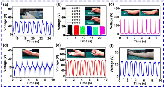
The prepared MCH-TENG exhibited flexibility, extensibility and shape adaptability. It can be attached to different moving parts of the human body to harvest biomechanical energy. As mentioned above, the positive and negative ions in the MCH further promote the charge transfer by forming another triboelectric layer at the surface of the MCH electrode and the silicone rubber. To prove this, Voc of the MCH-TENG was investigated under tensile conditions, as shown in Fig. 7a. In the process of stretching the MCH-TENG (see Movie S4†), the output voltage was 40 V, illustrating that there was indeed a triboelectrification effect between the MCH and the silicone rubber. Similar double triboelectric layers were observed in TENGs with the SA–Zn hydrogel prepared from sodium alginate and poly(acrylicacrylamide) as the electrode because there is a small air gap between the hydrogel and the package layer.46 To further demonstrate the excellent properties of the MCH as an electrode, the TENG was pressed gently at different parts by a finger and the voltage output signal was obtained. The pressed sites 1–6 are marked in the photograph of the 2# MCH-TENG (Fig. S4†). The Voc value was between 30 and 40 V (Fig. 7b). Obviously, the generated electrical signal was mainly transmitted through the MCH. These results prove that the MCH is an excellent flexible electrode material. Fig. 7c illustrates that the 2# MCH-TENG can harvest energy by gentle hand tapping. The Voc value was about 250 V. Fig. 7d shows the voltage results of the 2# MCH-TENG adhered to the wrist of a volunteer. It can collect the movement energy from bending his wrist. When he bent his wrist up and down, the 2# MCH-TENG bent elastically, separating from or contacting with his wrist skin, resulting in a Voc value of about 25 V. Due to the flexibility of the 2# MCH-TENG, it can also collect the energy of palm grip (Fig. 7e). The Voc value was about 120 V. When the 2# MCH-TENG was placed inside the elbow, it can collect elbow motion energy with a Voc value of about 30 V (Fig. 7f). These results confirm that the flexible and stretchable MCH-TENG can harvest low-frequency biomechanical energy from human motion and monitor human physiological activities.
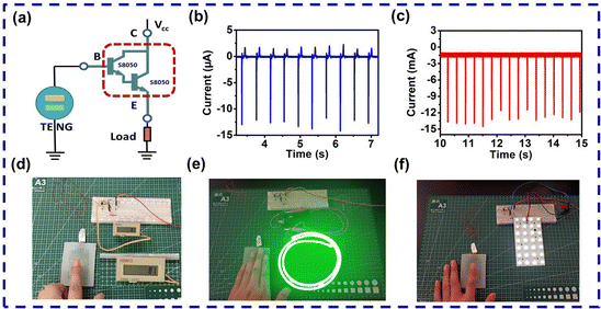
In order to explore new applications of the MCH-TENG, a current amplification circuit composed of the MCH-TENG and a Darlington transistor was designed. A Darlington transistor is a new equivalent triode composed of two triodes connected in series. The magnification of the equivalent triode is the product of the magnification of the two original triodes. Therefore, a Darlington transistor is characterized by a very high magnification rate. The function of a Darlington transistor is generally to amplify very small signals in highly sensitive amplification circuits. Based on the characteristics of the MCH-TENG, we combined the MCH-TENG and a Darlington transistor to form a pulse electronic switching circuit (Fig. 8a). The triode used was S8050. For comparison, the Isc value of the 2# MCH-TENG without connecting to the Darlington transistor and the external load was about 12 μA by tapping with one hand (Fig. 8b). The 2# MCH-TENG was then connected to the base of the Darlington transistor. Without an external load, the measured current was about 12 mA after amplification by the Darlington transistor (Fig. 8c). The current amplification factor was about 1000 times. Moreover, it was found that the voltage VCE between the collector and emitter had no significant effect on the current amplification coefficient when the Darlington transistor worked in the amplification state (Fig. S5†). This result was consistent with the basic characteristics of the triode. Fig. 8d shows the results when the load was an electronic pulse counter (Vcc = 5 V). When the forward pulse current generated by the MCH-TENG was inputted as the base current IB, a large current signal IE was generated at the emitter by the Darlington transistor. When a pulse signal appeared, the counter counted once and the value increased by one (see Fig. 8d and Movie S5†). Fig. 8e shows the results when the load was a one-meter LED neon strip (Vcc = 12 V). After the pulse current signal generated by gently tapping the MCH-TENG was amplified by the Darlington transistor, the LED neon strip can be powered up (see Fig. 8e and Movie S6†). This result justifies that the circuit can be used as a flashing switch for LED neon lights for commercial advertisements. Surprisingly, this circuit was able to drive high capacity loads. The LED panel in Fig. 8f was composed of 4 groups of 7 LEDs connected in series. The total power of the lamp board was 28 W. After the current generated by tapping the MCH-TENG was amplified by the Darlington transistor, the LED panel can be lit up when only one finger tapped the silicone rubber surface (Vcc = 18 V, see Fig. 8f and Movie S7†). This result demonstrated that the circuit was highly sensitive and can be used as an electronic switch for high-power loads, which has potential applications in the field of human–machine interaction.
3. Conclusion
In summary, in this study, a commercial, biocompatible and low-cost MCH has been selected as a flexible electrode to prepare TENGs for the first time. A flexible and stretchable MCH-TENG based on the MCH has been developed for harvesting bio-mechanical energy from human motions to power wearable electronics and electronic switches. The fabricated MCH-TENG (40 × 60 mm2) has exhibited high electrical outputs (Voc of 400 V, σsc of 53 μC m−2, and Pmax of 444.44 mW m−2) and a stable signal output without deterioration after 22![[thin space (1/6-em)]](https://www.rsc.org/images/entities/char_2009.gif) 500 cycles of repeated contact–separation motion. Additionally, combined with a Darlington transistor, the flexible MCH-TENG has also been successfully explored as an electronic switch. The device can drive electronic counters, LED strips and panels. This work demonstrates the application prospect of a commercial MCH as a stretchable electrode in the fabrication of TENGs for stretchable power sources. The obtained MCH-TENG is expected to have great potential application in wearable electronic products, soft robots, biomedical monitoring, and other fields in the future.
500 cycles of repeated contact–separation motion. Additionally, combined with a Darlington transistor, the flexible MCH-TENG has also been successfully explored as an electronic switch. The device can drive electronic counters, LED strips and panels. This work demonstrates the application prospect of a commercial MCH as a stretchable electrode in the fabrication of TENGs for stretchable power sources. The obtained MCH-TENG is expected to have great potential application in wearable electronic products, soft robots, biomedical monitoring, and other fields in the future.
4. Experiment section
4.1 Materials
A medical conductive hydrogel (viscosity: 15![[thin space (1/6-em)]](https://www.rsc.org/images/entities/char_2009.gif) 000–80
000–80![[thin space (1/6-em)]](https://www.rsc.org/images/entities/char_2009.gif) 000 mPa s; pH: 5.5–9.0; conductivity: 10.0–85.0 mS cm−1 at 25 °C) was bought from Suzhou Letai Medical Technology Co., Ltd. Silicone rubber (Ecoflex 00-30) was supplied by Smooth-On, Inc. Conductive cloth was purchased from Jingdong mall online.
000 mPa s; pH: 5.5–9.0; conductivity: 10.0–85.0 mS cm−1 at 25 °C) was bought from Suzhou Letai Medical Technology Co., Ltd. Silicone rubber (Ecoflex 00-30) was supplied by Smooth-On, Inc. Conductive cloth was purchased from Jingdong mall online.
4.2 Fabrication of the MCH-TENG based on the medical conductive hydrogel
Two acrylic molds were prepared by laser cutting. One had a groove structure, and the other had a rectangular bulge in the middle of the groove. The matrix and curing agent (1![[thin space (1/6-em)]](https://www.rsc.org/images/entities/char_2009.gif) :
:![[thin space (1/6-em)]](https://www.rsc.org/images/entities/char_2009.gif) 1, volume ratio) of the liquid silicone rubber were mixed evenly, and poured into the acrylic mold (80 × 60 mm2, depth of 3 mm) with a rectangular bulge (60 × 40 mm2, height of 2 mm) and the acrylic mold with a groove structure (80 × 60 mm2, depth of 0.5 mm). The silicone liquid solidified naturally at room temperature. Afterwards, the cured silicone rubber structures were taken out of the molds. Then, a copper wire or conductive cloth with different areas was attached to one side of a silicone rubber structure. The two silicone rubber structures were sealed together along the edges (10 mm) with liquid silicone rubber to obtain a silicone rubber sheet with a cavity (60 × 40 × 2 mm3). The MCH was injected into the cavity by using a syringe and the whole cavity was filled. The volume of the hydrogel used was 4800 mm3. To ensure the smooth injection process and the absence of pressure build-up inside the cavity, another syringe was used to pump air out of the cavity. After this process, the flexible and stretchable MCH-TENG was prepared.
1, volume ratio) of the liquid silicone rubber were mixed evenly, and poured into the acrylic mold (80 × 60 mm2, depth of 3 mm) with a rectangular bulge (60 × 40 mm2, height of 2 mm) and the acrylic mold with a groove structure (80 × 60 mm2, depth of 0.5 mm). The silicone liquid solidified naturally at room temperature. Afterwards, the cured silicone rubber structures were taken out of the molds. Then, a copper wire or conductive cloth with different areas was attached to one side of a silicone rubber structure. The two silicone rubber structures were sealed together along the edges (10 mm) with liquid silicone rubber to obtain a silicone rubber sheet with a cavity (60 × 40 × 2 mm3). The MCH was injected into the cavity by using a syringe and the whole cavity was filled. The volume of the hydrogel used was 4800 mm3. To ensure the smooth injection process and the absence of pressure build-up inside the cavity, another syringe was used to pump air out of the cavity. After this process, the flexible and stretchable MCH-TENG was prepared.
4.3 Characterization and measurements
When measuring the electrical properties of the MCH-TENG, a commercial linear motor (LinMot E1100) was employed to provide power with a stable and adjustable frequency. Defatted cowhide was used to simulate human skin as a pair of friction materials for the MCH-TENG. The Voc, Qsc, and Isc values were recorded by using a high impedance Keithley 6514 electrometer. The mechanical tensile test of the silicone rubber was performed by using a microcomputer controlled electronic tensile testing machine (CMT2103).Author contributions
Junwei Zhao: data curation, formal analysis, software, investigation, writing, methodology, and supervision; Yujiang Wang: review; Bo Wang: review; Yuetan Sun: synthesis and characterization; Haoqiang Lv: synthesis and characterization; Zijian Wang: software and characterization; Wenqing Zhang: software and characterization; Yongdong Jiang: supervision and writing – review & editing. All authors reviewed the manuscript.Conflicts of interest
The authors declare that they have no known competing financial interests or personal relationships that could have appeared to influence the work reported in this paper.Acknowledgements
This work was supported by the National Natural Science Foundation of China (no. 11204122, 61971211) and Key Scientific Research Project of Colleges and Universities in Henan Province (23A430039).References
- X. Cheng, X. Xue, Y. Ma, M. Han, W. Zhang, Z. Xu, H. Zhang and H. Zhang, Nano Energy, 2016, 22, 453–460 CrossRef CAS.
- M. Wu, X. Wang, Y. Xia, Y. Zhu, S. Zhu, C. Jia, W. Guo, Q. Li and Z. Yan, Nano Energy, 2022, 95, 106967 CrossRef CAS.
- X. Zhao, Z. Wang, Z. Liu, S. Yao, J. Zhang, Z. Zhang, T. Huang, L. Zheng, Z. L. Wang and L. Li, Nano Energy, 2022, 96, 107067 CrossRef CAS.
- J. Zhao, Y. Wang, X. Song, A. Zhou, Y. Ma and X. Wang, Nanoscale, 2021, 13, 18363–18373 RSC.
- Y.-T. Jao, P.-K. Yang, C.-M. Chiu, Y.-J. Lin, S.-W. Chen, D. Choi and Z.-H. Lin, Nano Energy, 2018, 50, 513–520 CrossRef CAS.
- J. Han, C. Xu, J. Zhang, N. Xu, Y. Xiong, X. Cao, Y. Liang, L. Zheng, J. Sun, J. Zhai, Q. Sun and Z. L. Wang, ACS Nano, 2021, 15, 1597–1607 CrossRef CAS PubMed.
- S. Zhu, Y. Xia, Y. Zhu, M. Wu, C. Jia and X. Wang, Nano Energy, 2022, 96, 107116 CrossRef CAS.
- C. Jia, Y. Xia, Y. Zhu, M. Wu, S. Zhu and X. Wang, Adv. Funct. Mater., 2022, 2201292 CrossRef CAS.
- J. Yang, J. An, Y. Sun, J. Zhang, L. Zu, H. Li, T. Jiang, B. Chen and Z. L. Wang, Nano Energy, 2022, 97, 107199 CrossRef CAS.
- G. Chen, Y. Li, M. Bick and J. Chen, Chem. Rev., 2020, 120, 3668–3720 CrossRef CAS PubMed.
- G. Chen, X. Xiao, X. Zhao, T. Tat, M. Bick and J. Chen, Chem. Rev., 2022, 122, 3259–3291 CrossRef CAS PubMed.
- N. Zhang, F. Huang, S. Zhao, X. Lv, Y. Zhou, S. Xiang, S. Xu, Y. Li, G. Chen, C. Tao, Y. Nie, J. Chen and X. Fan, Matter, 2020, 2, 1260–1269 CrossRef.
- X. Xiao, X. Xiao, Y. Zhou, X. Zhao, G. Chen, Z. Liu, Z. Wang, C. Lu, M. Hu, A. Nashalian, S. Shen, K. Xie, W. Yang, Y. Gong, W. Ding, P. Servati, C. Han, S. X. Dou, W. Li and J. Chen, Sci. Adv., 2021, 7, eabl3742 CrossRef CAS PubMed.
- P. Zhang, Y. Chen, Z. H. Guo, W. Guo, X. Pu and Z. L. Wang, Adv. Funct. Mater., 2020, 30, 1909252 CrossRef CAS.
- Y. Yang, N. Sun, Z. Wen, P. Cheng, H. Zheng, H. Shao, Y. Xia, C. Chen, H. Lan, X. Xie, C. Zhou, J. Zhong, X. Sun and S.-T. Lee, ACS Nano, 2018, 12, 2027–2034 CrossRef CAS PubMed.
- C. Dong, A. Leber, T. Das Gupta, R. Chandran, M. Volpi, Y. Qu, T. Nguyen-Dang, N. Bartolomei, W. Yan and F. Sorin, Nat. Commun., 2020, 11, 3537 CrossRef CAS PubMed.
- F. R. Fan, Z. Q. Tian and Z. Lin Wang, Nano Energy, 2012, 1, 328 CrossRef CAS.
- Y. Zhu, Y. Xia, M. Wu, W. Guo, C. Jia and X. Wang, Nano Energy, 2022, 98, 107309 CrossRef CAS.
- Z. Yan, L. Wang, Y. Xia, R. Qiu, W. Liu, M. Wu, Y. Zhu, S. Zhu, C. Jia, M. Zhu, R. Cao, Z. Li and X. Wang, Adv. Funct. Mater., 2021, 31, 2100709 CrossRef CAS.
- L. Wang, W. Liu, Z. Yan, F. Wang and X. Wang, Adv. Funct. Mater., 2021, 31, 2007221 CrossRef CAS.
- Y. Liu, W. Liu, Z. Wang, W. He, Q. Tang, Y. Xi, X. Wang, H. Guo and C. Hu, Nat. Commun., 2020, 11, 1599 CrossRef CAS PubMed.
- Y. Guo, Y. Chen, J. Ma, H. Zhu, X. Cao, N. Wang and Z. L. Wang, Nano Energy, 2019, 60, 641–648 CrossRef CAS.
- G. Liu, S. Xu, Y. Liu, Y. Gao, T. Tong, Y. Qi and C. Zhang, Adv. Funct. Mater., 2020, 30, 1909886 CrossRef CAS.
- J. Wang, P. Cui, J. Zhang, Y. Ge, X. Liu, N. Xuan, G. Gu, G. Cheng and Z. Du, Nano Energy, 2021, 89, 106320 CrossRef CAS.
- G.-L. Ni, X. Zhu, H.-Y. Mi, P.-Y. Feng, J. Li, X. Jing, B. Dong, C. Liu and C. Shen, Nano Energy, 2021, 87, 106148 CrossRef CAS.
- L. Zhou, L. Liu, W. Qiao, Y. Gao, Z. Zhao, D. Liu, Z. Bian, J. Wang and Z. L. Wang, ACS Nano, 2021, 15, 19684–19691 CrossRef CAS PubMed.
- T. Cheng, Y. Li, Y.-C. Wang, Q. Gao, T. Ma and Z. L. Wang, Nano Energy, 2019, 60, 137–143 CrossRef CAS.
- X. Zhang, Q. Yang, P. Ji, Z. Wu, Q. Li, H. Yang, X. Li, G. Zheng, Y. Xi and Z. L. Wang, Nano Energy, 2022, 99, 107362 CrossRef CAS.
- B. Cheng, J. Ma, G. Li, S. Bai, Q. Xu, X. Cui, L. Cheng, Y. Qin and Z. L. Wang, Adv. Energy Mater., 2020, 10, 2000827 CrossRef CAS.
- J. Liao, Y. Zou, D. Jiang, Z. Liu, X. Qu, Z. Li, R. Liu, Y. Fan, B. Shi, Z. Li and L. Zheng, Nano Energy, 2020, 69, 104417 CrossRef CAS.
- Y. Zou, J. Liao, H. Ouyang, D. Jiang, C. Zhao, Z. Li, X. Qu, Z. Liu, Y. Fan, B. Shi, L. Zheng and Z. Li, Appl. Mater. Today, 2020, 20, 100699 CrossRef.
- B. Wang, X. Zhai, X. Wei, Y. Shi, X. Huo, R. Li, Z. Wu and Z. L. Wang, Nano Res., 2022, 15, 8435–8441 CrossRef.
- Z. Liu, Q. Zheng, Y. Shi, L. Xu, Y. Zou, D. Jiang, B. Shi, X. Qu, H. Li, H. Ouyang, R. Liu, Y. Wu, Y. Fan and Z. Li, J. Mater. Chem. B, 2020, 8, 3647–3654 RSC.
- S. Li, Z. Zhao, D. Liu, J. An, Y. Gao, L. Zhou, Y. Li, S. Cui, J. Wang and Z. L. Wang, Adv. Mater., 2022, 34, 2110363 CrossRef CAS PubMed.
- S. Cheon, H. Kang, H. Kim, Y. Son, J. Y. Lee, H.-J. Shin, S.-W. Kim and J. H. Cho, Adv. Funct. Mater., 2018, 28, 1703778 CrossRef.
- P.-Y. Feng, Z. Xia, B. Sun, X. Jing, H. Li, X. Tao, H.-Y. Mi and Y. Liu, ACS Appl. Mater. Interfaces, 2021, 13, 16916–16927 CrossRef CAS PubMed.
- C. Wu, T. W. Kima, S. Sung, J. H. Park and F. Li, Nano Energy, 2018, 44, 279–287 CrossRef CAS.
- M. Wu, Z. Gao, K. Yao, S. Hou, Y. Liu, D. Li, J. He, X. Huang, E. Song, J. Yu and X. Yu, Mater. Today Energy, 2021, 20, 100657 CrossRef CAS.
- Z. Qin, D. Dong, M. Yao, Q. Yu, X. Sun, Q. Guo, H. Zhang, F. Yao and J. Li, ACS Appl. Mater. Interfaces, 2019, 11, 21184–21193 CrossRef CAS PubMed.
- X. Jing, H. Li, H.-Y. Mi, P.-Y. Feng, X. Tao, Y. Liu, C. Liu and C. Shen, ACS Appl. Mater. Interfaces, 2020, 12, 23474–23483 CrossRef CAS PubMed.
- H.-Y. Mi, X. Jing, Y. Wang, X. Shi, H. Li, C. Liu, C. Shen, L.-S. Turng and S. Gong, ACS Appl. Polym. Mater., 2020, 2, 5219–5227 CrossRef CAS.
- H. Sun, Y. Zhao, C. Wang, K. Zhou, C. Yan, G. Zheng, J. Huang, K. Dai, C. Liu and C. Shen, Nano Energy, 2020, 76, 105035 CrossRef CAS.
- G. Li, L. Li, P. Zhang, C. Chang, F. Xu and X. Pu, RSC Adv., 2021, 11, 17437–17444 RSC.
- S.-H. Jeong, Y. Lee, M.-G. Lee, W. J. Song, J.-U. Park and J.-Y. Sun, Nano Energy, 2021, 79, 105463 CrossRef CAS.
- Z. Liu, Y. Wang, Y. Ren, G. Jin, C. Zhang, W. Chen and F. Yan, Mater. Horiz., 2020, 7, 919–927 RSC.
- F. Sheng, J. Yi, S. Shen, R. Cheng, C. Ning, L. Ma, X. Peng, W. Deng, K. Dong and Z. L. Wang, ACS Appl. Mater. Interfaces, 2021, 13, 44868–44877 CrossRef CAS PubMed.
- H. Zou, Y. Zhang, L. Guo, P. Wang, X. He, G. Dai, H. Zheng, C. Chen, A. C. Wang, C. Xu and Z. L. Wang, Nat. Commun., 2019, 10, 1427 CrossRef PubMed.
- Z. Ren, L. Wu, Y. Pang, W. Zhang and R. Yang, Nano Energy, 2022, 100, 107522 CrossRef CAS.
- X. Luo, L. Zhu, Y.-C. Wang, J. Li, J. Nie and Z. L. Wang, Adv. Funct. Mater., 2021, 31, 2104928 CrossRef CAS.
- L. Jia, Z. H. Guo, L. Li, C. Pan, P. Zhang, F. Xu, X. Pu and Z. L. Wang, ACS Nano, 2021, 15, 19651–19660 CrossRef CAS PubMed.
- L. Shi, S. Dong, P. Ding, J. Chen, S. Liu, S. Huang, H. Xu, U. Farooq, S. Zhang, S. Li and J. Luo, Nano Energy, 2019, 55, 548–557 CrossRef CAS.
- Y. Long, Y. Chen, Y. Liu, G. Chen, W. Guo, X. Kang, X. Pu, W. Hu and Z. L. Wang, Nanoscale, 2020, 12, 12753–12759 RSC.
- S. Niu, S. Wang, L. Lin, Y. Liu, Y. S. Zhou, Y. Hu and Z. L. Wang, Energy Environ. Sci., 2013, 6, 3576 RSC.
- F. Yi, X. Wang, S. Niu, S. Li, Y. Yin, K. Dai, G. Zhang, L. Lin, Z. Wen, H. Guo, J. Wang, M.-H. Yeh, Y. Zi, Q. Liao, Z. You, Y. Zhang and Z. L. Wang, Sci. Adv., 2016, 2, e1501624 CrossRef PubMed.
- X. Wang, Y. Yin, F. Yi, K. Dai, S. Niu, Y. Han, Y. Zhang and Z. You, Nano Energy, 2017, 39, 429–436 CrossRef CAS.
- Y. Yang, J. Han, J. Huang, J. Sun, Z. L. Wang, S. Seo and Q. Sun, Adv. Funct. Mater., 2020, 30, 1909652 CrossRef CAS.
- Y.-C. Lai, J. Deng, S. Niu, W. Peng, C. Wu, R. Liu, Z. Wen and Z. L. Wang, Adv. Mater., 2016, 28, 10024–10032 CrossRef CAS PubMed.
- S. Niu, Y. Liu, S. Wang, L. Lin, Y. S. Zhou, Y. Hu and Z. L. Wang, Adv. Funct. Mater., 2014, 24, 3332–3340 CrossRef CAS.
- C. Jacquemoud, K. Bruyere-Garnier and M. Coret, J. Biomech., 2007, 40, 468–475 CrossRef CAS PubMed.
- N. Cui, L. Gu, Y. Lei, J. Liu, Y. Qin, X. Ma, Y. Hao and Z. L. Wang, ACS Nano, 2016, 10, 6131–6138 CrossRef CAS PubMed.
- N. Cui, J. Liu, Y. Lei, L. Gu, Q. Xu, S. Liu and Y. Qin, ACS Appl. Energy Mater., 2018, 1, 2891–2897 CrossRef CAS.
- C. Xin, Z. Li, Q. Zhang, Y. Peng, H. Guo and S. Xie, Nano Energy, 2022, 100, 107448 CrossRef CAS.
- T. Liu, M. Liu, S. Dou, J. Sun, Z. Cong, C. Jiang, C. Du, X. Pu, W. Hu and Z. L. Wang, ACS Nano, 2018, 12, 2818–2826 CrossRef CAS PubMed.
Footnote |
| † Electronic supplementary information (ESI) available. See DOI: https://doi.org/10.1039/d2nr05706a |
| This journal is © The Royal Society of Chemistry 2023 |

