
Chemically synthesized poly(3,4-ethylenedioxythiophene) conducting polymer as a robust electrocatalyst for highly efficient dye-sensitized solar cells†
Masud
 abc,
Md.
Aftabuzzaman
a,
Haoran
Zhou
ad,
Saehyun
Kim
b,
Jaekyung
Yi
e,
Sarah S.
Park
e,
Youn Soo
Kim
*b and
Hwan Kyu
Kim
*a
abc,
Md.
Aftabuzzaman
a,
Haoran
Zhou
ad,
Saehyun
Kim
b,
Jaekyung
Yi
e,
Sarah S.
Park
e,
Youn Soo
Kim
*b and
Hwan Kyu
Kim
*a
aGlobal GET-Future Lab., Department of Advanced Materials Chemistry, Korea University, 2511 Sejong-ro, Sejong 339-700, Republic of Korea. E-mail: hkk777@korea.ac.kr
bDepartment of Materials Science and Engineering, Pohang University of Science and Technology (POSTECH), 77 Cheongam-Ro, Nam-Gu Pohang, Gyeongbuk, Republic of Korea. E-mail: ysookim@postech.ac.kr
cDepartment of Biomedical Engineering, College of Life Science and Biotechnology, Dongguk University, Seoul 04620, Republic of Korea
dRenewable Energy Materials Laboratory (REML), Advanced Institute of Convergence Technology, Seoul National University, Suwon 16229, Republic of Korea
eDepartment of Chemistry, Pohang University of Science and Technology (POSTECH), Pohang 37673, Republic of Korea
First published on 1st July 2024
Abstract
Chemically synthesized PEDOT (poly(3,4-ethylenedioxythiophene)) nanomaterials, with various nanostructured morphologies as well as different intrinsic electrical conductivities and crystallinities, were compared as electrocatalysts for Co(III) reduction in dye-sensitized solar cells (DSSCs). Electrochemical parameters, charge transfer resistance toward the electrode/electrolyte interface, catalytic activity for Co(III)-reduction, and diffusion of cobalt redox species greatly depend on the morphology, crystallinity, and intrinsic electrical conductivity of the chemically synthesized PEDOTs and optimization of the fabrication procedure for counter electrodes. The PEDOT counter electrode, fabricated by spin coating a DMSO-dispersed PEDOT solution with an ordered 1D structure and nanosized fibers averaging 70 nm in diameter and an electrical conductivity of ∼16 S cm−1, exhibits the lowest charge transfer resistance, highest diffusion for a cobalt redox mediator and superior electrocatalytic performance compared to a traditional Pt-counter electrode. The photovoltaic performance of the DSSC using chemically synthesized PEDOT exceeds that of a Pt-electrode device because of the enhanced current density, which is directly related to the superior electrocatalytic ability of PEDOT for Co(III)-reduction. This simple spin-coated counter electrode prepared using cheap and scalable chemically synthesized PEDOT can be a potential alternative to the expensive Pt-counter electrode for cobalt and other redox electrolytes in DSSCs and various flexible electronic devices.
1. Introduction
Conducting polymers (CPs) possess delocalized conjugated structures, which are widely studied and applied as electrocatalysts and photocatalysts in various energy-related devices, sensors, and environmental remediation because of their excellent catalytic ability, tunable electrical conductivities, and unique electrochemical and optical properties.1–5 Dye-sensitized solar cells (DSSCs) are emerging photovoltaics, which mimic natural photosynthesis to convert light to electricity. The essential requirements of an electrocatalyst for DSSCs are high electrical conductivity, large surface area, and low charge transfer resistance in the electrode/electrolyte interface. A conducting polymer can fulfill all requirements to be an efficient counter electrode for DSSCs. Generally, platinum is widely used as an electrocatalyst in DSSCs because of its high catalytic ability and low charge transfer resistance, especially for iodine electrolytes. However, some drawbacks of Pt-counter electrodes include high cost; low abundance; instability toward iodine electrolytes; reaction with iodine electrolytes and PtI4 formation, especially by a vapor deposited Pt thin layer;6 less effectiveness toward metal-complexes and organic redox mediators7 have encouraged researchers to find alternative efficient counter electrode catalysts for DSSCs. Because of the limitation of open circuit voltage (Voc), high volatility, and corrosion of the Ag grid due to iodine electrolytes, metal complexes such as Co complexes and Cu complexes are promising redox electrolytes to enhance Voc and overall efficiency of the device.8 The significant power conversion efficiency, about 14–15%, for DSSCs has been reported using cobalt and copper complex redox electrolytes.9–11 Therefore, the demand for alternative Pt-free counter electrodes, especially for cobalt and copper electrolytes, is very prominent, and a conducting polymer appears as a suitable candidate. Among the conducting polymers, polypyrrole,12,13 polyaniline,14 poly(3,4-ethylenedioxythiophene) (PEDOT), and their derivatives1,11,15–17 have been applied as electrocatalysts in DSSCs owing to their low cost and large-scale production, structural variation with nanoscale morphologies, tunable electrical conductivity, high chemical stability and low toxicity.Among the various conducting polymers, PEDOT can be a promising electrocatalyst material because of its high conductivity, excellent chemical and physical stability under ambient conditions, optical transparency in the visible range, and easy doping and synthesis.18,19 PEDOT can be synthesized by chemical oxidative polymerization or the electrodeposition process. Both processes follow the same oxidative mechanism. In electrodeposition, PEDOT is doped by the counteranion of electrolytes used for the electrochemical process, while in chemical synthesis, PEDOT is doped by the counteranion of the oxidant. The electrochemical synthesis limits the reaction on the surface of the conducting electrode substrate, and nanostructured PEDOT deposits on the substrate as a film. On the other hand, chemically synthesized PEDOTs are powdery nanomaterials and can be easily scaled up.20
The remarkable advancement for DSSC has been obtained using the PEDOT conducting polymer-based counter electrodes.1,15 In most cases, PEDOTs are electrodeposited on the fluorine-doped tin oxide (FTO) coated glass substrate to fabricate efficient counter electrodes for cobalt and copper electrolytes.1,15 However, for large-scale production and application in flexible devices, chemical oxidative synthesis can be a better option. The performance of the chemically synthesized PEDOT as an electrocatalyst depends on the nanostructural morphology, conductivity, crystallinity, chemical and thermal stability; these can be varied on the synthetic conditions, e.g., concentration and type of oxidant, counter anion of the oxidant, temperature, surfactants, and reaction medium. Therefore, depending on the application, an effective synthetic procedure of PEDOT is required. There are few reports about chemically synthesized PEDOT for the application as an electrocatalyst counter electrode in DSSCs and, in most cases, with iodine electrolytes.21,22 Their reported synthetic conditions were also somewhat different in terms of temperature and surfactant concentration applied here, which can affect the morphology and electrical properties of the nanomaterials.21,22
In this study, four different types of PEDOT nanomaterials were synthesized by aqueous chemical oxidative polymerization at room temperature by varying oxidants, the concentration of oxidant, and the presence or absence of surfactant to obtain PEDOTs with different nanostructural morphology, intrinsic electrical conductivity, and crystallinity. The counter electrode was developed by spin-coating the dispersed PEDOT solution in a dimethyl sulfoxide (DMSO) solvent without using any binder and drying in a vacuum oven at 70 °C. The green solvent DMSO was chosen because it can effectively disperse the synthesized nanoparticles while maintaining their as-synthesized nanostructure morphology, as confirmed through high-resolution scanning electron microscopy (SEM) imaging. Here, the developed simple procedure for the counter electrode by chemically synthesized PEDOT can be comparable, even superior, to drop-casted Pt-counter electrode and can be an alternative for cobalt redox electrolytes and other redox electrolyte systems.
2. Results and discussion
2.1 Chemically synthesized PEDOT nanomaterials
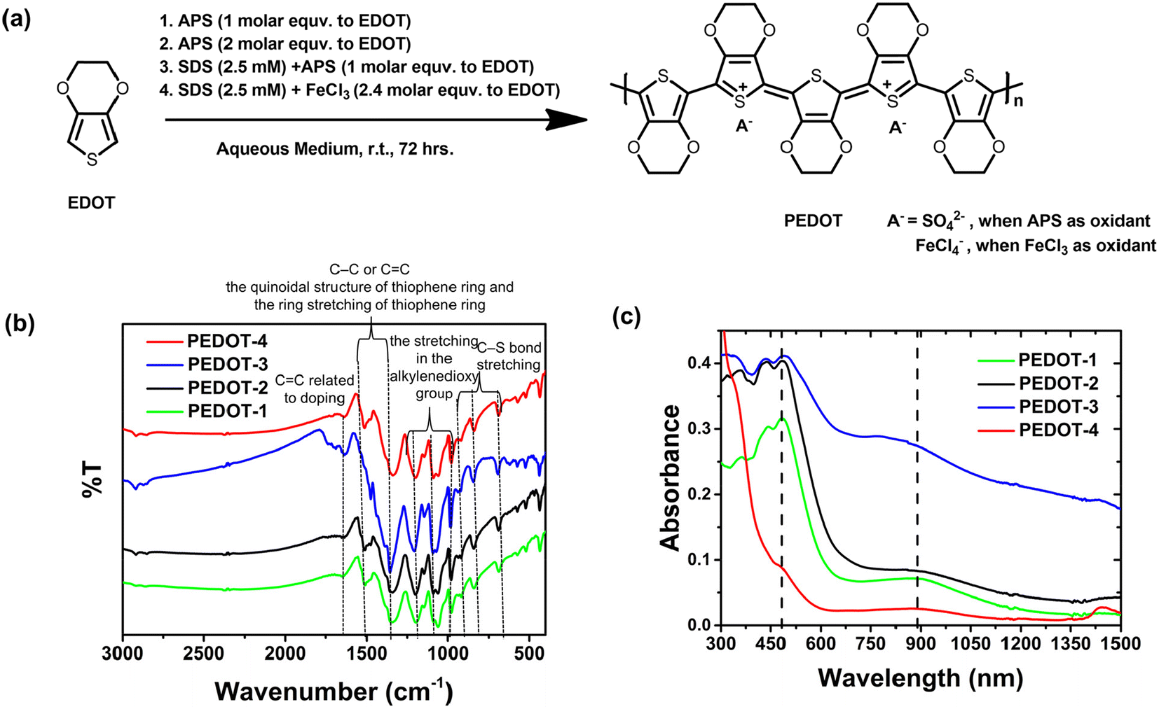 | ||
| Fig. 1 (a) Synthetic route to PEDOT-nanomaterials, (b) FT-IR of the synthesized PEDOT nanopowders, and (c) UV-Vis-NIR absorption spectroscopy of the dispersed PEDOT in DMSO. | ||
The chemically synthesized PEDOTs were characterized by elemental analysis (see Table S1†), FT-IR (see Fig. 1b),25,26 UV-vis-NIR absorption spectroscopy (see Fig. 1c), and energy dispersive X-ray spectroscopy (EDS) elemental mapping (see Fig. S1†). The PEDOT obtained by APS oxidative polymerization is most probably doped by available sulfate ions produced in the reaction.27,28 The ν3 band of the sulfate around ∼1090 cm−1 can be overlapped with the PEDOT band in the IR spectrum.28 The doping level of sulfate in the APS synthesized PEDOTs can be estimated from elemental analysis from the consideration of all elemental carbon coming from PEDOT and sulfur coming from either thiophane ring in PEDOT or sulfate dopant according to the procedure of Chiu et al. (see Table S1†).28 The EDS elemental mapping shows the distribution of carbon, sulfur, oxygen, and chloride in chemically synthesized PEDOT nanomaterials (see Fig. S1†). In the FT-IR spectrum (see Fig. 1b), the peaks at 1337 and 1514 cm−1 correspond to the C–C or C![[double bond, length as m-dash]](https://www.rsc.org/images/entities/char_e001.gif) C stretching frequencies of the quinoid structure and ring stretching of the thiophene ring.26,29 The stretching of the alkylenedioxy groups corresponds to the vibration at 1200, 1141, and 1087 cm−1.26 The peaks at 982, 842, and 689 cm−1 correspond to the C–S bond stretching in the thiophene ring.26,29 The existence of the vibration band around 1640 cm−1 was related to the doping level of the chemically synthesized PEDOTs, which is probably due to the CC bond according to the report of Fichet et al.30,31 All chemically synthesized PEDOTs, dispersed in DMSO, show characteristic absorption peaks at 400–700 nm due to π–π* transitions along the polymer chain (see UV-vis-NIR absorption spectra in Fig. 1c).31–33 The oxidized state of PEDOT (polaron/bipolaron) can be attributed to the broad absorption band at 750–1050 nm, maxima ∼880 nm, (see Fig. 1c).31,33 The estimation of the exact molecular weight of PEDOTs was difficult due to the insolubility or partial solubility of the PEDOT nanomaterials in organic or water media.
C stretching frequencies of the quinoid structure and ring stretching of the thiophene ring.26,29 The stretching of the alkylenedioxy groups corresponds to the vibration at 1200, 1141, and 1087 cm−1.26 The peaks at 982, 842, and 689 cm−1 correspond to the C–S bond stretching in the thiophene ring.26,29 The existence of the vibration band around 1640 cm−1 was related to the doping level of the chemically synthesized PEDOTs, which is probably due to the CC bond according to the report of Fichet et al.30,31 All chemically synthesized PEDOTs, dispersed in DMSO, show characteristic absorption peaks at 400–700 nm due to π–π* transitions along the polymer chain (see UV-vis-NIR absorption spectra in Fig. 1c).31–33 The oxidized state of PEDOT (polaron/bipolaron) can be attributed to the broad absorption band at 750–1050 nm, maxima ∼880 nm, (see Fig. 1c).31,33 The estimation of the exact molecular weight of PEDOTs was difficult due to the insolubility or partial solubility of the PEDOT nanomaterials in organic or water media.
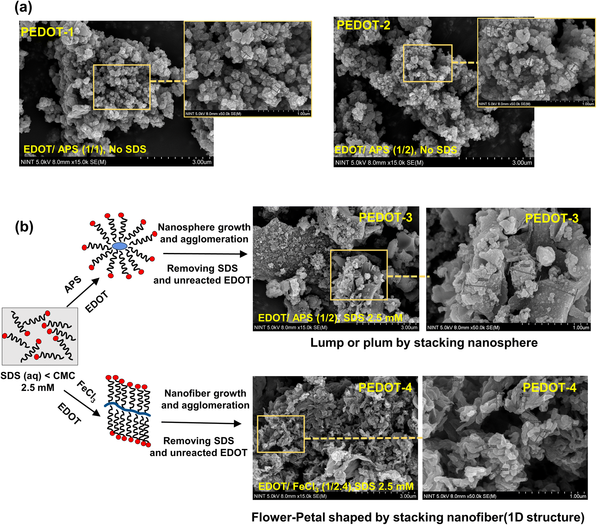 | ||
| Fig. 2 (a) SEM images of the chemically synthesized PEDOTs using the APS oxidant with varying EDOT to APS concentrations. (b) Morphology of PEDOT-3 and PEDOT-4 synthesized using the APS and FeCl3 oxidant, respectively, in the presence of 2.5 mM SDS surfactant. | ||
The N2 adsorption/desorption isotherm and detailed N2 adsorption parameters used to derive the Brunauer–Emmett–Teller (BET) surface area for different as-prepared dry PEDOT nanomaterials are shown in Fig. 3 and Table S3,† respectively. The pore size distribution was determined using NLDFT (non-local density functional theory) adsorption models for carbon slit-shaped pores, as shown in the inset of Fig. 3.
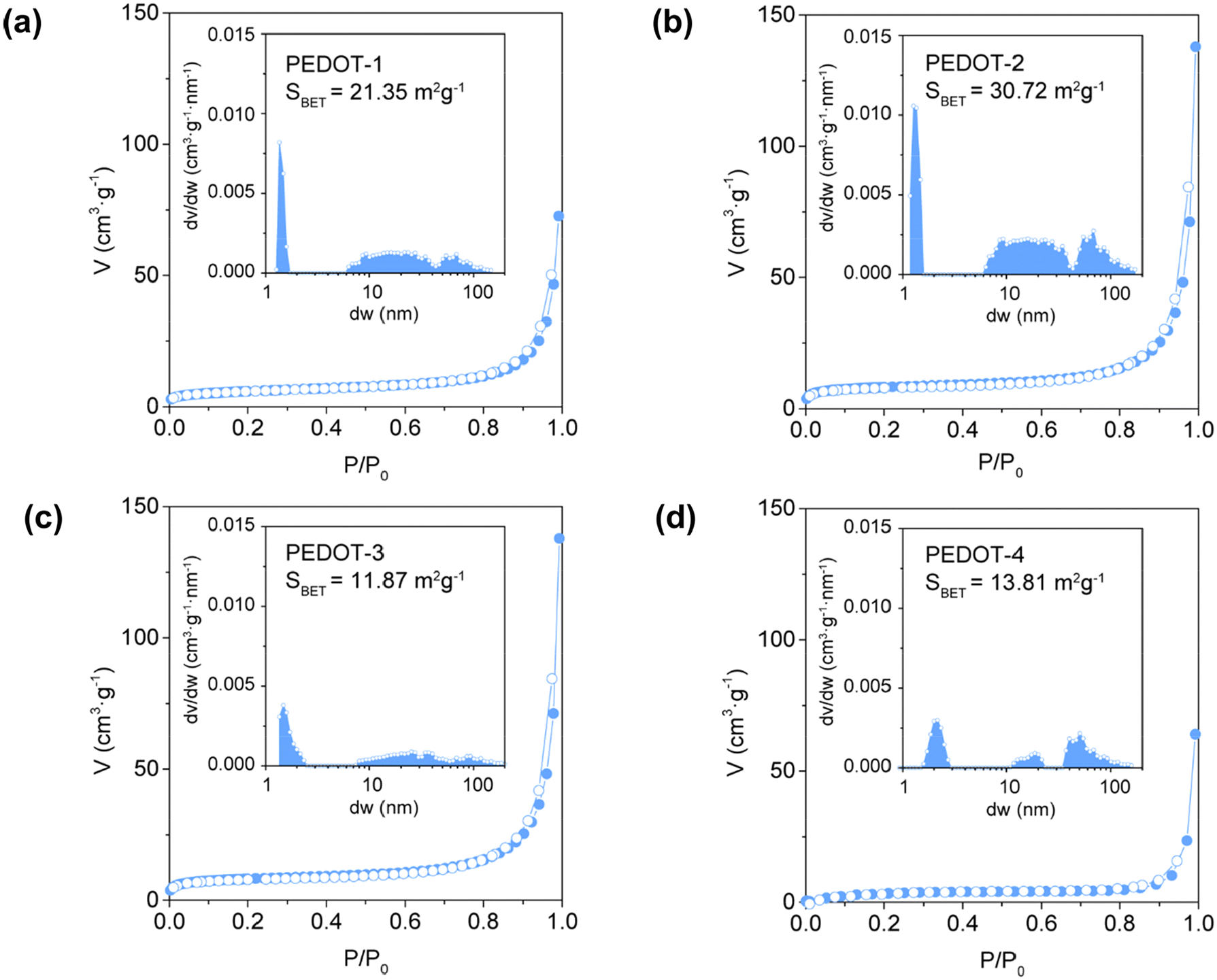 | ||
| Fig. 3 N2 adsorption/desorption isotherms with inset figures representing pore size distribution based on N2 adsorption branch using NLDFT models for carbon slit-shaped pores of (a) PEDOT-1, (b) PEDOT-2, (c) PEDOT-3, and (d) PEDOT-4. | ||
PEDOT-1, PEDOT-2, PEDOT-3, and PEDOT-4 exhibit BET surface areas of 21.35 m2 g−1, 30.72 m2 g−1, 11.87 m2 g−1, and 13.50 m2 g−1, respectively. The pore size distribution analysis reveals that the pores range from microporous (<2 nm) to macroporous (>50 nm), covering a broad spectrum of pore widths. Since PEDOT-1 and PEDOT-2 have 0D structures (see Fig. 2), they inherently possess large BET surface areas. PEDOT-2 has the highest BET surface area, which is due to its comparatively smaller particle size than PEDOT-1. On the other hand, the use of a surfactant in the synthesis of PEDOT-3 significantly reduced the BET surface area. This reduction is because of the aggregation and accumulation of nanospheres, forming larger, plum-shaped particles. The BET surface area for PEDOT-4 was slightly higher than that of PEDOT-3 because the change of the oxidant in the presence of a surfactant resulted in a flower-petal-shaped morphology composed of stacked 1D nanofibers with nanosized diameters. Although the BET surface area of PEDOT-4 was lower than that of the 0D PEDOT-1 and PEDOT-2 due to the 1D nature and aggregation of nanofibers in PEDOT-4, it may still provide an extensive surface area. This is because the extended nature of the 1D nanofibers and their reduced aggregation in dispersed solutions offer advantages over 0D PEDOT-1 and PEDOT-2.
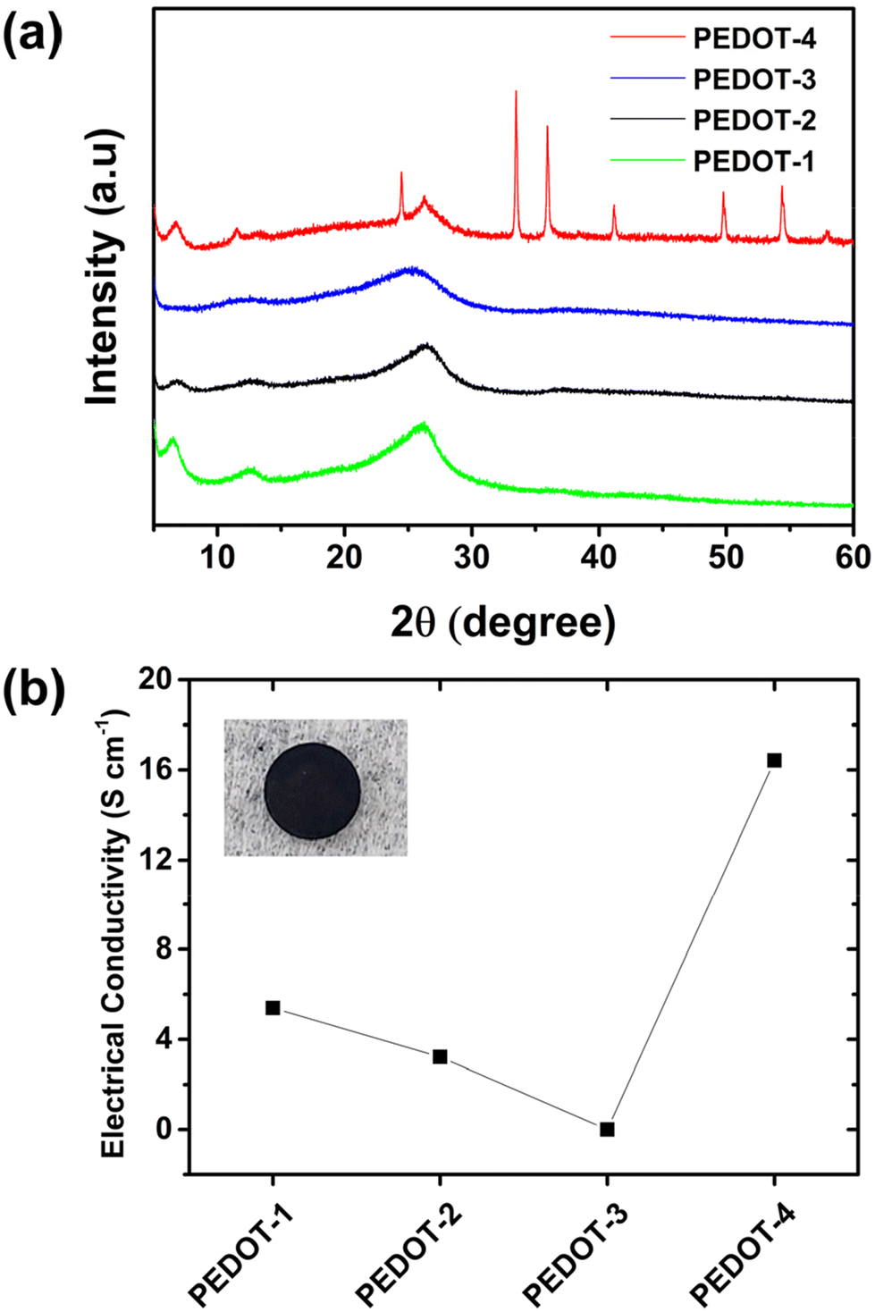 | ||
| Fig. 4 The comparison of (a) XRD-patterns, and (b) intrinsic electrical conductivity of four different types of PEDOTs. | ||
The intrinsic electrical conductivity of the chemically synthesized PEDOTs depends on the extent of doping, morphology, and nanoparticle size. The trend of intrinsic electrical conductivity of chemically synthesized PEDOTs at room temperature is shown in Fig. 4b. The highest electrical conductivity (∼16.4 S cm−1) was found for PEDOT-4. The high electrical conductivity of PEDOT-4 correlates with its as-synthesized high doping level (confirmed from the XRD pattern, Fig. 4a) and 1D-structural morphology (see Fig. 2b), which are suitable for electron transfer. The negligible electrical conductivity of PEDOT-3 was due to its low-doped or undoped state, confirmed by XRD patterns and elemental analysis. The moderate electrical conductivity found for chemically synthesized PEDOT-1 and PEDOT-2 by APS oxidant can be correlated to their doping level (see Fig. 4b and Table S1†) and particle size (see Fig. 2a and Table S2†). All chemically synthesized PEDOT nanomaterials were thermally stable up to 200 °C in an air-oxidizing atmosphere (see TGA curves in Fig. S2†).
2.2 Morphology and electrochemical characterization of the PEDOT counter electrode
The morphology, particle size, and electrical conductivity of PEDOT are essential factors in controlling its electrocatalytic performance. PEDOT-1 and PEDOT-2 have similar particle sizes, morphologies, BET surface area, and electrical conductivities. Therefore, to compare different PEDOTs, three types of PEDOT nanomaterials (PEDOT-2, PEDOT-3, and PEDOT-4) were utilized to fabricate the counter electrode. These three PEDOTs have different particle sizes, different electrical conductivities, and different morphologies. The chemically synthesized PEDOTs can be well dispersed in DMSO, DMF, or NMP. Typically, DMSO/methanol or methanol was used to disperse PEDOT nanomaterials for spin coating.21,22 Here, the single solvent DMSO was used to disperse chemically synthesized PEDOT nanomaterials for spin coating due to its non-toxicity, polarity, and high donor number. The spin-coated PEDOT on the FTO substrate was then used as a counter electrode to fabricate symmetrical dummy cells and dye-sensitized solar cells. First, the morphology of the spin-coated PEDOT film on the FTO substrate was checked by FE-SEM (see Fig. 5). SEM analysis of the prepared counter electrode was performed directly without any thin Pt-conductive layer.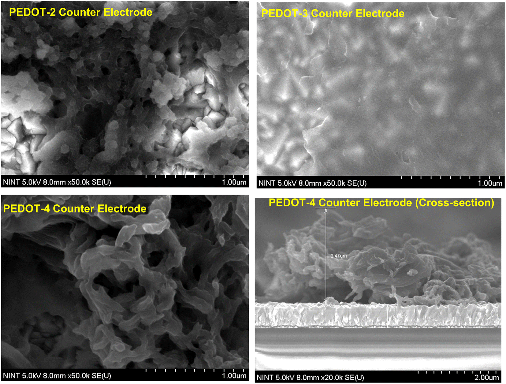 | ||
| Fig. 5 FE-SEM images of the three different PEDOT-counter electrodes. | ||
In the PEDOT-2 counter electrode, the aggregated nanosized particles were randomly distributed on the FTO substrate with some pores. A dense PEDOT layer was formed on the FTO substrate in the PEDOT-3 counter electrode. The obtained SEM image of the PEDOT-3 counter electrode was vague due to the low intrinsic electrical conductivity of the PEDOT-3 nanomaterial. In the case of the PEDOT-4 counter electrode, a flower-petal-shaped film was formed by nano-sized PEDOT fibers with some pores on an FTO substrate (see Fig. 5). The high conductivity and large surface area can be suitable for increasing the catalytic activity and electron transfer to the electrode/electrolyte interface. The PEDOT-4 counter electrode, which features a continuous flower-petal shape with a high surface area due to its extended 1D nanofiber structure, can be a suitable and efficient counter electrode. It is noted that in our optimized system utilizing spin-coating with DMSO solvent, the PEDOT nanomaterials can be randomly distributed on the FTO substrate while retaining their bulk morphology. However, due to this random distribution, the thickness is not uniform across the substrate. Analysis of the cross-sectional SEM image of our best PEDOT-4 counter electrode reveals variations in thickness ranging from nanometers to micrometers. The maximum thickness was 2.47 μm (see Fig. 5).
The electrochemical impedance (EIS) and liner scan voltammetry (LSV) measurement of the symmetrical dummy cell by various PEDOT-counter electrodes using cobalt electrolytes were performed to determine the charge transfer resistance in the electrode/electrolyte interface, diffusion of the redox species, and electrocatalytic performance. At first, Nyquist plots of the three PEDOT-counter electrodes were compared, as shown in Fig. 6a. Usually two semicircles should be obtained in Nyquist plots of the symmetrical dummy cells; the first semicircle represents the charge transfer resistance (Rct) at the electrode/electrolyte interface, and the second semicircle is related to the diffusion resistance of electrolytes redox species. In the case of PEDOT-2 and PEDOT-3, three semicircles were obtained, the first small semicircle in the high-frequency region in PEDOT-2 and PEDOT-3 is likely attributed to the transmission resistance of the electron (Rtm) on the PEDOT surface while second semicircle represent Rct at the PEDOT electrode/electrolyte interface.36 The additional semicircle in the high-frequency region due to the probable electron transmission resistance can be attributed to the discontinuous morphology of the PEDOT-2 counter electrode, despite the moderate intrinsic electrical conductivity of PEDOT-2. In the case of PEDOT-3, this probable electron transmission resistance (first small semicircle) can be attributed to the very poor intrinsic electrical conductivity of PEDOT-3 and the dense morphology of the PEDOT-3 counter electrode. However, there was no such electron transport resistance observed in the PEDOT-4 counter electrode. This can be attributed to its continuous morphology, achieved through stacked 1D nanofibers, and the high intrinsic electrical conductivity of PEDOT-4.
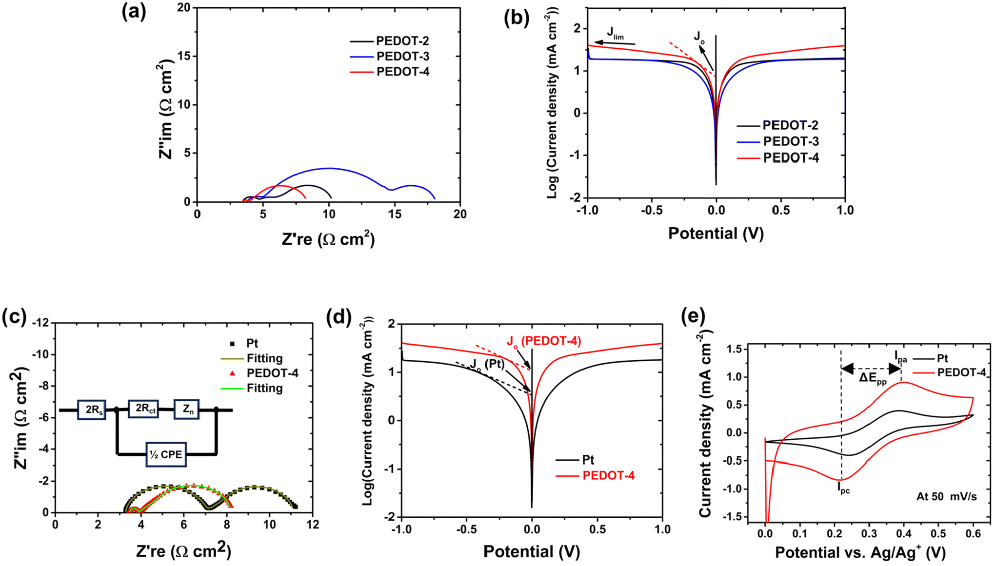 | ||
| Fig. 6 Comparing (a) Nyquist plots and (b) Tafel plots of three different counter electrodes. Comparing (c) Nyquist plots, (d) Tafel plots, and (e) cyclic voltammograms of the best PEDOT-counter electrode with the Pt-counter electrode. | ||
The wide 2nd semicircles of PEDOT-3 represent its extremely high Rct in the electrode/electrolyte interface compared with the Rct of the other two PEDOTs. The high Rct in the electrode/electrolyte interface of PEDOT-3 can be correlated to its film morphology (dense layer) and very low intrinsic electrical conductivity, which is unsuitable for fast electron transfer to catalyze the cobalt(III) reduction. The Rct value in the electrode/electrolyte interface decreases in the following order: PEDOT-3 > PEDOT-2 > PEDOT-4. The Rct value in the electrode/electrolyte interface depends on the morphology, surface area, and intrinsic electrical conductivity. The ordered 1D-structure of PEDOT-4 with intrinsic electrical conductivity of about 16 S cm−1 can efficiently transfer charge to Co3+ redox species. The Tafel polarization curves of the symmetrical cells using various PEDOTs counter electrodes were compared, as shown in Fig. 6b. The Tafel curve consists of three zones: polarization zone (curve at low potential, usually <120 mV), Tafel zone (curve at middle potential) and limiting diffusion zone (curve at high potential).37 The exchange current density (Jo) and limiting current density (Jlim) are two important parameters that can be obtained from the Tafel polarization curves to describe the electrocatalytic performance. The Jo value can be obtained by extending the tangent line to the zero voltage from the Tafel zone. The current density of the intersection of the cathodic branch and the equilibrium potential line can be described as Jo. The Jo value is inversely correlated with change transfer resistance; therefore, the higher Jo value indicates higher catalytic ability.37,38 The Jlim can be obtained by extending the tangent line from the diffusion zone and the intersection of the cathodic branch with the Y-axis regarded as Jlim (see Fig. 6b). Jlim is directly correlated with the diffusion of the redox species. The higher Jlim indicates faster diffusion of redox species in the electrode.39 Among the three types of PEDOT electrodes, PEDOT-4 exhibits the highest Jo and Jlim, while PEDOT-3 exhibits the lowest Jo and Jlim. Therefore, the catalytic ability of different PEDOT counter electrodes is in the following order: PEDOT-4 > PEDOT-2 >PEDOT-3. The Nyquist plot and Tafel polarization curve of the best PEDOT-4 counter electrode and Pt-electrodes were compared, as shown in Fig. 6c and d. The significant reduction of Rct and remarkable increment of Jo and Jlim for PEDOT-4 compared with Pt (see Fig. 6c and d) indicate the superior electrocatalytic ability of PEDOT-4 over Pt toward Co3+ reduction reaction.
The cyclic voltammogram (CV) of the best PEDOT counter electrode (PEDOT-4) was also compared with the CV of the Pt-counter electrode. The CV of the counter electrode was performed using a three-electrodes system, where Ag/AgCl and Pt-wire acted as a reference electrode and a counter electrode, respectively. Drop-cast Pt-or spin-coated PEDOT on the FTO substrate was used as a working electrode. The electrolytes solution for CV analysis was prepared by diluting cobalt electrolytes (100 times) with an additional 0.1 M LiClO3 in acetonitrile. In the CV curve, the cathodic peak represents Co3+ reduction, and the anodic peak is related to Co2+ oxidation.
A high peak current density (Ip) correlates with the high catalytic activity of the counter electrode and lower peak-to-peak separation (ΔEpp) relates to higher electrochemical rates of redox reactions.40–42 The higher cathodic peak current density (Ipc, PEDOT-4 −0.84 mA cm−2) than that of Pt-counter electrode (Ipc, Pt, −0.40 mA cm−2) and comparable ΔEpp for PEDOT-4 (ΔEpp, PEDOT-4 0.18 V) with Pt (ΔEpp, pt 0.14 V) at 50 mV s−1 scan rate (see Fig. 6e, Fig. S3 and Table S4†) indicate that PEDOT-4 can be the best alternative of Pt catalyst for the Co3+ reduction reaction.
2.3 Photovoltaic performance of dye-sensitized solar cell using spin-coated chemically synthesized PEDOT counter electrode
Based on the electrochemical parameters described in the previous section, PEDOT-2, and PEDOT-4 counter electrodes were utilized to fabricate full cells and compare with the device of Pt-electrode. Here, our developed porphyrin dye, SGT-021,43 was used to fabricate DSSC with cobalt electrolytes and PEDOT-counter electrodes. The J–V curves under simulated 1-sun conditions are shown in Fig. 7a and summarized in Table 1.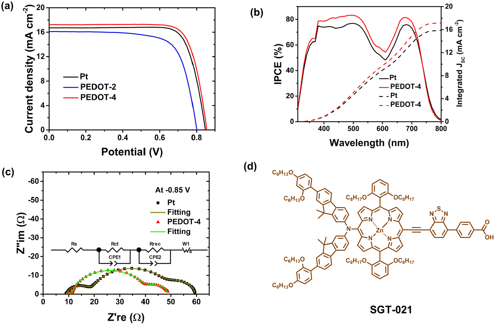 | ||
| Fig. 7 (a) J–V curves, (b) IPCE with integrated current density, and (c) Nyquist plots of DSSCs using PEDOT and Pt-counter electrodes. (d) The structure of porphyrin dye used to fabricate the device. | ||
| Device | J sc (mA cm−2) | V oc (mV) | FF (%) | PCE (%) | J sc IPCE (mA cm−2) |
|---|---|---|---|---|---|
| a The average value was reported from the results of three devices with the margin of error (95% confidence level). The device's active area was 0.3 cm2, and the J–V measurement was performed with a black metal mask with an aperture area of 0.141 cm2. The composition of the cobalt electrolytes was 0.22 M [Co2+(bpy)3](TFSI)2, 0.05 M [Co3+(bpy)3] (TFSI)3, 0.1 M LiTFSI and 0.8 M TBP in acetonitrile. | |||||
| Pt | 16.72 (16.34 ± 0.37) | 848 (853 ± 5.30) | 78.41 (79.54 ± 1.12) | 11.11 (11.09 ± 0.03) | 15.89 |
| PEDOT-2 | 16.10 (15.36 ± 1.25) | 801 (797 ± 6.02) | 72.18 (72.76 ± 1.62) | 9.31 (8.90 ± 0.61) | — |
| PEDOT-4 | 17.24 (17.17 ± 0.09) | 855 (852 ± 7.67) | 78.38 (78.48 ± 0.12) | 11.56 (11.47 ± 0.16) | 17.15 |
SGT-021 dye is a promising dye for cobalt electrolytes because of its 0.28 V driving force, enabling efficient dye regeneration by cobalt(II) redox species,44 and its broad visible light absorption (see IPCE spectrum in Fig. 7b). Using the PEDOT-4 counter electrode, excellent power conversion efficiency (PCE) of 11.6% was achieved, which was higher than that for PCE (11.1%) of the device using the Pt-counter electrode. The enhancement of PCE using PEDOT-4 counter electrode was because of significant enhancement of Jsc with comparable Voc, which directly reflects the superior electrocatalytic ability of PEDOT-4 over Pt for Co3+-reduction reaction. The enhanced Jsc value for the PEDOT-4 device was correlated with the IPCE spectrum with integrated Jsc value (see Fig. 7b).
The EIS of PEDOT-4 and Pt-devices were performed under dark conditions at −0.85 V at room temperature to compare the recombination resistance (Rrec) and charge transfer resistances (Fig. 7c and Table 2).
| Device | R s (Ω) | R ct (CE) (Ω) | R rec (Ω) | R w (Ω) |
|---|---|---|---|---|
| Pt | 8.95 | 9.78 | 27.32 | 13.33 |
| PEDOT-4 | 9.67 | 1.46 | 27.12 | 10.62 |
Similar Rrec values for these two devices indicate their comparable Voc. However, lower charge transfer resistance in the counter electrode (Rct (CE)) and diffusion resistance (Rw) again ensured the reason for the higher Jsc value for the PEDOT-4-device (see Table 2 and Fig. 7c). Using the PEDOT-2 counter electrode, the PCE was relatively low because of low Jsc, Voc, and FF, which indicated its poor catalytic ability for Co3+ reduction. It is noted that to obtain high photovoltaic performance, optimization of the counter electrodes is also quite an important factor. Here, excellent PCE was obtained due to the fabrication of the device using the optimized counter electrode. The use of DMSO solvent in spin-coating plays a crucial role in retaining the surface morphology of the 1D-structure for PEDOT-4, suitable to catalyze the Co3+ reduction by fast transferring electrons to the redox species of the electrolytes. PEDOT nanomaterials synthesized here are stable (see our TGA data in Fig. S2†), indicating stability in the range of 200–300 °C under an air-oxidizer atmosphere. The initial stability test of the DSSC using a PEDOT-counter electrode was tested under ambient conditions. After 200 hours, no significant loss of photovoltaic performance was found (see the comparison of J–V curves of the fresh and aged cell in Fig. S4†). Here, the counter electrode was developed by chemically synthesized PEDOT, which is cheap and scalable, and fabricated by a simple spin-coating process with the green solvent, DMSO. The drying temperature of this counter electrode was 70 °C in a vacuum oven. Therefore, this PEDOT counter electrode can be fabricated on a flexible substrate to form a flexible DSSC. The developed counter electrode by chemically synthesized PEDOT can compete with the traditional Pt counter electrodes and be an effective alternative to expensive Pt-counter electrodes.
3. Conclusions
Chemically synthesized PEDOTs with diverse structural morphologies and electrochemical properties were evaluated as electrocatalysts for cobalt(III) reduction. PEDOTs (PEDOT-1 and PEDOT-2) obtained by aqueous oxidative polymerization by APS have nano structural morphology with particle size around 114–130 nm and moderate intrinsic electrical conductivity (3–6 S cm−1). Using the SDS surfactant below the CMC level at room temperature, the APS oxidant produces plum/lump-shaped agglomerated PEDOT (PEDOT-3). In contrast, the FeCl3 oxidant produces PEDOT (PEDOT-4) with flower petal morphology stacked by 1D nanofibers having comparatively small (∼70 nm) diameters. The chemically synthesized PEDOT-4 exhibits maximum electrical conductivity (∼16 S cm−1), while PEDOT-3 gives the lowest electrical conductivity. The chemically synthesized PEDOT was deposited on the FTO substrate by spin-coating dispersed solution in green solvent DMSO. The morphology of the PEDOT-4 counter electrode has a continuous 1D structure formed by stacking nanofibers. Among three different PEDOTs, PEDOT-4 exhibits the lowest charge transfer resistance, even lower than Pt, at the electrode/electrolyte interface and better electrocatalytic ability toward Co3+-reduction, characterized by EIS, LSV, and CV analysis. The better electrocatalytic ability of PEDOT-4 directly correlates to its highly ordered 1D-structure with high surface area and excellent intrinsic electrical conductivity, suitable for fast electron transfer toward Co3+ redox species. The electrocatalytic ability of PEDOTs directly influences the photovoltaic performance of DSSC. The outstanding PCE of 11.6% was achieved using chemically synthesized PEDOT (PEDOT-4), which has a 1D structure and excellent intrinsic electrical conductivity. The photovoltaic performance of the device using spin-coated PEDOT-4 was superior to the performance of the device using the traditional Pt-electrode because of the remarkable enhancement of current density, which is directly related to the excellent electrocatalytic and fast charge transfer ability of PEDOT-4 toward Co3+ redox species. Here, the developed simple and convenient fabrication of counter electrodes by chemically synthesized PEDOT-4, which is cheap and scalable, can be suitable to fabricate flexible DSSCs with cobalt, copper, or other electrolyte systems. Since PEDOT-1 and PEDOT-2 have nanostructural morphology with moderate electrical conductivity, by proper optimization, these nanomaterials also have potential in other applications.Author contributions
Masud, Y. S. K., and H. K. K. conceived the idea and designed the experiment. Masud synthesized the materials, conducted the characterization of the materials, and fabricated and characterized the devices. M. A. conducted cyclic voltammetry and electrochemical validation. H. Z. synthesized and provided the dye. J. Y. and S. K. conducted the N2 adsorption/desorption isotherms analysis for BET surface area measurement of the nanomaterials. S. S. P. validated the BET surface area and pore size distribution analysis. Masud wrote the manuscript with contributions from M. A., H. Z., J. Y., S. S. P, Y. S. K., and H. K. K., Y. S. K, and H. K. K supervised the work. All authors contributed to the review of the manuscript.Data availability
Data for this article, including the data supporting this article, are available at Materials Data Facility at https://doi.org/10.18126/3j2f-1h39.Conflicts of interest
There are no conflicts to declare.Acknowledgements
This work was supported by the Korean government (Ministry of Science, ICT, and Future Planning) through the Mid-career Researcher Program (NRF-2021R1A2C2006328) and “Human Resources Program in Energy Technology” of the Korea Institute of Energy Technology Evaluation and Planning (KETEP), granted financial resource from the Ministry of Trade, Industry & Energy, Republic of Korea (KETEP-20204030200070). This work was also supported by the National Research Foundation of Korea (NRF) grant funded by the Korean government (MSIT) (No RS-2024-00408795) and (No. RS-2024-00408989). This work was also supported by the 2023 POSTECH International Joint Research Project and the Korea TORAY Science Foundation.References
- H. Ellis, N. Vlachopoulos, L. Häggman, C. Perruchot, M. Jouini, G. Boschloo and A. Hagfeldt, Electrochim. Acta, 2013, 107, 45–51 CrossRef CAS.
- E. Miglbauer, P. J. Wójcik and E. D. Głowacki, Chem. Commun., 2018, 54, 11873–11876 RSC.
- N. Aydemir, J. Malmström and J. Travas-Sejdic, Phys. Chem. Chem. Phys., 2016, 18, 8264–8277 RSC.
- Q. Zhou and G. Shi, J. Am. Chem. Soc., 2016, 138, 2868–2876 CrossRef CAS.
- A. Tundwal, H. Kumar, B. J. Binoj, R. Sharma, R. Kumari, A. Yadav, G. Kumar, A. Dhayal, A. Yadav, D. Singh, B. Mangla and P. Kumar, Coord. Chem. Rev., 2024, 500, 215533 CrossRef CAS.
- E. Olsen, G. Hagen and S. E. Lindquist, Sol. Energy Mater. Sol. Cells, 2000, 63, 267–273 CrossRef CAS.
- H. Tian, Z. Yu, A. Hagfeldt, L. Kloo and L. Sun, J. Am. Chem. Soc., 2011, 133, 9413–9422 CrossRef CAS PubMed.
- Masud and H. K. Kim, ACS Omega, 2023, 8, 6139–6163 CrossRef CAS PubMed.
- J. M. Ji, H. Zhou, Y. K. Eom, C. H. Kim and H. K. Kim, Adv. Energy Mater., 2020, 10, 1–12 Search PubMed.
- K. Kakiage, Y. Aoyama, T. Yano, K. Oya, J. I. Fujisawa and M. Hanaya, Chem. Commun., 2015, 51, 15894–15897 RSC.
- Y. Ren, D. Zhang, J. Suo, Y. Cao, F. T. Eickemeyer, N. Vlachopoulos, S. M. Zakeeruddin, A. Hagfeldt and M. Grätzel, Nature, 2023, 613, 60–65 CrossRef CAS PubMed.
- W. Hou, Y. Xiao, G. Han and H. Zhou, Electrochim. Acta, 2016, 190, 720–728 CrossRef CAS.
- S. Lu, S. Wang, R. Han, T. Feng, L. Guo, X. Zhang, D. Liu and T. He, J. Mater. Chem. A, 2014, 2, 12805–12811 RSC.
- Q. Tang, H. Cai, S. Yuan and X. Wang, J. Mater. Chem. A, 2013, 1, 317–323 RSC.
- Y. Cao, Y. Liu, S. M. Zakeeruddin, A. Hagfeldt and M. Grätzel, Joule, 2018, 2, 1108–1117 CrossRef CAS.
- A. A. Lima, G. T. Tractz, A. G. Macedo, F. Thomazi, P. R. P. Rodrigues and C. A. Dartora, Opt. Mater., 2022, 132, 112763 CrossRef.
- C.-T. Li, C.-P. Lee, Y.-Y. Li, M.-H. Yeh and K.-C. Ho, J. Mater. Chem. A, 2013, 1, 14888–14896 RSC.
- L. Groenendaal, F. Jonas, D. Freitag, H. Pielartzik and J. R. Reynolds, Adv. Mater., 2000, 12, 481–494 CrossRef CAS.
- S. Nie, Z. Li, Y. Yao and Y. Jin, Front. Chem., 2021, 9, 1–8 Search PubMed.
- C. Li, H. Bai and G. Shi, Chem. Soc. Rev., 2009, 38, 2397–2409 RSC.
- T. H. Lee, K. Do, Y. W. Lee, S. S. Jeon, C. Kim, J. Ko and S. S. Im, J. Mater. Chem., 2012, 22, 21624–21629 RSC.
- N. Jeon, D. K. Hwang, Y. S. Kang, S. S. Im and D. W. Kim, Electrochem. Commun., 2013, 34, 1–4 CrossRef CAS.
- N. Paradee and A. Sirivat, Polym. Int., 2014, 63, 106–113 CrossRef CAS.
- R. Corradi and S. P. Armes, Synth. Met., 1997, 84, 453–454 CrossRef CAS.
- J. W. Choi, M. G. Han, S. Y. Kim, S. G. Oh and S. S. Im, Synth. Met., 2004, 141, 293–299 CrossRef CAS.
- W. Feng, Y. Li, J. Wu, H. Noda, A. Fujii, M. Ozaki and K. Yoshino, J. Phys.: Condens. Matter, 2007, 19, 186220 CrossRef PubMed.
- D. A. House, Chem. Rev., 1962, 62, 185–203 CrossRef CAS.
- W. W. Chiu, J. Travaš-Sejdić, R. P. Cooney and G. A. Bowmaker, Synth. Met., 2005, 155, 80–88 CrossRef CAS.
- Y. Wang, K. Cai and X. Yao, ACS Appl. Mater. Interfaces, 2011, 3, 1163–1166 CrossRef CAS PubMed.
- O. Fichet, F. Tran-Van, D. Teyssie and C. Chevrot, Thin Solid Films, 2002, 411, 280–288 CrossRef CAS.
- J. Jang, M. Chang and H. Yoon, Adv. Mater., 2005, 17, 1616–1620 CrossRef CAS.
- M. G. Han and S. H. Foulger, Small, 2006, 2, 1164–1169 CrossRef CAS PubMed.
- T. Bahry, Z. Cui, A. Deniset-Besseau, M. Gervais, C. Sollogoub, T.-T. Bui and S. Remita, New J. Chem., 2018, 42, 8704–8716 RSC.
- Y. Rharbi and M. A. Winnik, J. Am. Chem. Soc., 2002, 124, 2082–2083 CrossRef CAS.
- T. Kawai, M. Nakazono and K. Yoshino, J. Mater. Chem., 1992, 2, 903–906 RSC.
- M. Aftabuzzaman, M. S. Ahmed, K. Matyjaszewski and H. K. Kim, Chem. Eng. J., 2022, 446, 137249 CrossRef CAS.
- S. Yun, M. Wu, Y. Wang, J. Shi, X. Lin, A. Hagfeldt and T. Ma, ChemSusChem, 2013, 6, 411–416 CrossRef CAS.
- R. Kumar, V. Sahajwalla and P. Bhargava, Nanoscale Adv., 2019, 1, 3192–3199 RSC.
- M. Aftabuzzaman, C. K. Kim, H. Zhou and H. K. Kim, Nanoscale, 2020, 12, 1602–1616 RSC.
- J. D. Roy-Mayhew, D. J. Bozym, C. Punckt and I. A. Aksay, ACS Nano, 2010, 4, 6203–6211 CrossRef CAS.
- F. Gong, H. Wang, X. Xu, G. Zhou and Z.-S. Wang, J. Am. Chem. Soc., 2012, 134, 10953–10958 CrossRef CAS PubMed.
- J.-M. Ji, C. K. Kim and H. K. Kim, Dalton Trans., 2021, 50, 9399–9409 RSC.
- S. H. Kang, M. J. Jeong, Y. K. Eom, I. T. Choi, S. M. Kwon, Y. Yoo, J. Kim, J. Kwon, J. H. Park and H. K. Kim, Adv. Energy Mater., 2017, 7, 1602117 CrossRef.
- Masud, H. Zhou and H. K. Kim, Mater. Today Energy, 2023, 34, 101299 CrossRef CAS.
Footnote |
| † Electronic supplementary information (ESI) available. See DOI: https://doi.org/10.1039/d4nr00949e |
| This journal is © The Royal Society of Chemistry 2024 |