
Enhanced stability of boron modified NiFe hydroxide for oxygen evolution reaction†
Yewon
Hong‡
a,
Juhyung
Choi‡
 ab,
Eunchong
Lee
a and
Yun Jeong
Hwang
*ac
ab,
Eunchong
Lee
a and
Yun Jeong
Hwang
*ac
aDepartment of Chemistry, College of Natural Sciences, Seoul National University (SNU), Seoul 08826, Republic of Korea. E-mail: yjhwang1@snu.ac.kr
bInstitute for Data Innovation in Science, Seoul National University (SNU), Seoul 08826, Republic of Korea
cCenter for Nanoparticle Research, Institute for Basic Science (IBS), Seoul 08826, Republic of Korea
First published on 5th June 2024
Abstract
The introduction of non-metal elements including boron has been identified as a significant means to enhance oxygen evolution reaction (OER) performance in NiFe-based catalysts. To understand the catalytic activity and stability, recent attention has widened toward the Fe species as a potential contributor, prompting exploration from various perspectives. Here, boron incorporation in NiFe hydroxide achieves significantly enhanced activity and stability compared to the boron-free NiFe hydroxide. The boron inclusion in NiFe hydroxide is found to show exceptionally improved stability from 12 to 100 hours at a high current density (200 mA cm−2). It facilitates the production and redeposition of OER-active, high-valent Fe species in NiFe hydroxide based on the operando Raman, UV-vis, and X-ray absorption spectroscopy analysis. It is proposed that preserving a homogenous distribution of Fe across the boron-containing catalyst surface enhances OER stability, unlike the bare NiFe hydroxide electrocatalyst, which exhibits uneven Fe dissolution, confirmed through elementary mapping analysis. These findings shed light on the potential of anionic regulation to augment the activity of iron, an aspect not previously explored in depth, and thus are expected to aid in designing practical OER electrocatalysts.
1. Introduction
Electrochemical catalytic reactions such as hydrogen evolution reaction, CO2 reduction reaction, and nitrogen reduction reaction are important as they enable the synthesis of value-added chemical products sustainably by utilizing renewable energy sources with zero carbon emission.1–4 As the universal anodic half-reaction to the cathodic reactions, the electrochemical oxygen evolution reaction (OER) has attracted the attention of researchers as it only requires water as a reactant, thus being an essential reaction to achieve carbon neutrality.5 However, commercial usage in the industrial field is hindered as it kinetically requires large overpotentials arising from the four consecutive electron transfer steps to attain industrial-level current densities. In addition, the fact that the most efficient and durable electrocatalysts are scarce and costly noble metal-based catalysts is another major obstacle.6,7Recently, there has been much advancement within transition metal-based catalysts to replace the past noble-metal catalysts. Among those, nickel-iron hydroxides (NiFeOxHy) are seen as the most practical alternative, due to their high activity and abundance.8,9 For NiFeOxHy catalysts, Ni has been acknowledged as the predominantly responsible element of the active site for OER. When applying anodic potentials, Ni shows obvious electronic shifts to higher oxidation states and the apparent NiOOH phase evolution, investigated by operando X-ray absorption (XAS) and Raman spectroscopy.9 Therefore, catalyst design strategies were focused on promoting the activity of Ni by introducing foreign elements to induce higher oxidation states, which is known to stabilize OER intermediates more and promote oxygen production.10,11
On the other hand, although researchers state in unison that Fe is a crucial factor for high activity, Fe has been less highlighted due to the lack of apparent changes from operando observation.12 When Fe is incorporated, its Lewis acidity aids in the formation of more OER-active Ni4+.13–16 However, recent reports also elucidate the significance of Fe as an active component for OER because highly oxidized Fe is detected at oxygen-producing potentials by in situ Mössbauer spectroscopy and surface interrogation scanning electrochemical microscopy revealing that the ratio of Fe to Ni within the catalyst is correlated to the ratio of kinetically fast to slow active sites.17,18 Building on these findings, Hunter et al. detected the highly oxidized FeVIO42− species under the anodic condition in a nonaqueous electrolyte and found that upon the introduction of an alkaline solution, these species would diminish while producing oxygen, thus providing strong evidence of Fe as an OER active site.19
The Fe also becomes more emphasized from the perspective of stability. A study of pristine Fe (oxy)hydroxides and Fe–M (M = Ni or Co) (oxy)hydroxides elaborated that OER active Fe requires a stable host material. Otherwise, it would suffer from severe dissolution and lead to low stability of the catalyst.20 Other types of research show that phase segregation or loss of Fe within the catalyst surface results in a catalytic dead site and performance loss.21 The NiFe catalysts often showed the drawback of low stability when operating at high current densities (>100 mA cm−2). Researchers have suggested various approaches such as implementing more Fe into the electrolyte to prevent the leaching of Fe from the catalyst to build practical electrocatalysts that not only have high activity but also long-term stability.22 However, there are debates regarding the effects of and the roles of Fe within NiFe catalysts, and for these reasons, profound efforts are required to comprehend the contribution of Fe, and strategies should be devised to develop effective methodologies for preserving durable Fe and ensuring the sustained performance of OER.
Meanwhile, one of the key strategies for the designing of practical and highly active electrocatalysts is non-metal regulation strategies, which introduce non-metal elements such as B, N, S, or P through intercalation within the hydroxide layers.23–28 The introduction of non-metal elements is proposed to be capable of modulating the electronic structure of the metal sites and tuning the covalency and bond strength between the metal and non-metal atoms, facilitating surface reconstruction, creating defects, or alleviating charge transfer to facilitate OER activity. These effects can be beneficial to reach high performances of the electrocatalysts. However, the elucidation on the higher performances is mostly centralized toward Ni instead of Fe, and thus the effects of non-metal regulation strategies on Fe are still not fully understood, such as whether it can promote the oxidation states of Fe, or whether it can affect the Fe dissolution/segregation. Although a recent report on NO3− incorporated NiFe catalyst demonstrated to remain within the catalyst, contrary to other non-metal atoms such as P and S, and retain the OER stability through its strong interaction with Fe, whether other non-metal elements can also have a strong interaction, promote the oxidation states, or affect the dissolution/segregation of Fe is still unknown29 similar to NO3−, another element that has been found to not leach out and thus continuously interact with metal hydroxide surfaces is boron.9,30–32 Recent advances in boron inclusion achieve promising improvement in OER activity with low overpotentials. However, the reason for higher performance upon boron inclusion is not well defined, especially from the perspective of Fe, and the impact of boron on stability is still premature, necessitating further investigation.
Herein, we constructed a B-containing NiFe hydroxide catalyst (B-NiFeOxHy) which features high OER activity and enhanced stability under high current density compared to the B-free counterpart. Through a series of material characterizations, we found that the interaction between Ni–B, as well as Fe–B was existent while maintaining the hydroxide crystal phase. We directly observed the more robust oxidation of Fe when boron was present in the electrocatalyst, indicating the production of OER active Fe and thus significantly enhancing the catalytic activity of NiFe hydroxide using operando UV-Vis spectroscopy and XAS analysis. The input of boron also resulted in a faster redeposition of Fe onto the surface of the catalyst and preserved the homogeneity of Fe spatial distribution on the catalyst surface. These results propose a robust catalytic active cycle of Fe facilitated by boron, preventing instability issues associated with Fe local structure or formation of Fe-poor sites. Our work provides an understanding of the activity and stability enhancement by the effect of boron incorporation from a perspective of Fe which has not been dealt with in depth before this study, and thus highlights boron engineering as a promising strategy to develop robust and durable OER electrocatalysts.
2. Experimental section
2.1. Synthesis of B-NiFeOxHy and NiFeOxHy
A chemical precipitation method reported in a previous study was modified and used to synthesize B-NiFeOxHy.31 In detail, a 0.118 M Ni(NO3)2·6H2O (Sigma Aldrich, ≥98.5%) solution and 0.118 M Fe(NO3)3·9H2O (Sigma Aldrich, ≥98%) solution were prepared respectively. Then, 2 mL of the Ni(NO3)2·6H2O solution and 0.5 mL of the Fe(NO3)3·9H2O solution were added into 4.773 mL of deionized (DI) water. After 10 min of stirring, 0.727 mL of NaBH4 (Sigma Aldrich, ≥98%) solution (1.635 M) was added slowly which created a black solution. The mixed solution was left for 2 h in an ice bath. The precipitants were collected using a centrifuge, washed with DI water three times, and dried in a vacuum oven. For the synthesis of NiFeOxHy, an equal molar amount of NaOH (Sigma Aldrich, ≥97%) was used in place of NaBH4.2.2. Material characterization
The surface morphology of materials was examined by scanning electron microscopy (SEM, Apreo 2S Hivac, Thermofisher Scientific) and Cs-corrected scanning transmission electron microscopy (Cs-STEM, JEOL JEM-ARM200F). The contents of the samples were confirmed using an inductively coupled plasma mass spectrometer (ICP-MS, PlasmaQuant MS Elite, analytik Jena). X-ray diffraction (XRD, Bruker D8 Advance) patterns were obtained to probe the crystalline structure of the samples. X-ray photoelectron spectroscopy (XPS, VersaProbe, PHI) was employed to obtain the surface valence state and composition of samples with Al Kα radiation. A field emission-electron probe micro analyzer (FE-EPMA, JXA-8530F, JEOL) was performed to scrutinize the bulk surface of the as-prepared electrodes.2.3. Electrochemical measurements
All electrochemical measurements were performed using a three-electrode system on a VSP-3e potentiostat (Biologic) with a Hg/HgO (1.0 M KOH) reference electrode and a platinum foil counter electrode. The working electrode was prepared by spraying a catalyst ink onto a carbon paper substrate, and the loaded amount of the catalyst was controlled to be 1 mg cm−2 with a fixed area (0.196 cm2). The catalyst ink mixture contained 1 mg of the as-synthesized catalyst, 990 μL of isopropanol, and 10 μL Nafion™ solution and was sonicated for 30 min to ensure homogeneous dispersion. The electrochemical surface reconstruction of the as-prepared B-NiFeOxHy and NiFeOxHy was carried out by conducting cyclic voltammetry (CV) in the potential range between 1.0 and 1.5 V (vs. RHE) at a scan rate of 20 mV s−1 until the current was saturated. A reverse polarization sweep was recorded to determine overpotentials of the catalyst through linear sweep voltammetry (LSV) at a scan rate of 5 mV s−1 ensuring accurate measurements without overestimation of the performance owing to the capacitive currents and pre-oxidation current of Ni2+/3+. Tafel slopes of the electrocatalysts were measured by using a rotating disk electrode (RDE, Pine Research Instruments) at a rotation rate of 1600 rpm. 0.25 mg cm−2 of each as-synthesized catalyst was loaded on the RDE electrode. Electrochemical impedance spectroscopy (EIS) under a constant potential of 1.5 V in a frequency range of 100 kHz to 500 mHz with an alternating current potential amplitude of 10 mV. All the measured potentials were reported against the reversible hydrogen electrode (RHE) using the following eqn (1):| E(vs. RHE) = E(vs. Hg/HgO) + 0.098 + 0.05916 × pH. | (1) |
The double-layer capacitance (Cdl) of the catalyst was calculated based on the CV curves obtained in a non-faradaic potential region (1.10 to 1.20 V) at various scan rates from 5 to 200 mV s−1. The slopes obtained from the graph depicting half of the capacitive current densities against the scan rate are indicative of the double-layer capacitance (Cdl). The electrochemical surface area (ECSA) of catalysts was determined through the formula: ECSA = Cdl/Cs, where Cs represents the nominal specific capacitance (Cs = 0.04 mF cm−2).8 Turnover Frequency (TOF) was estimated by the following eqn (2):
| TOF = j × Ageo/n × F × Nsite | (2) |
![[thin space (1/6-em)]](https://www.rsc.org/images/entities/char_2009.gif) 485 C mol−1), and the moles of metal sites on the electrode (Nsite) were determined through inductively coupled plasma mass spectrometry (ICP-MS). The long-term stability performances of sr_B-NiFeOxHy and sr_NiFeOxHy were recorded using a chronopotentiometry (CP) method and conducted in an H-cell using an anion exchange membrane (Sustanion X37-50 Grade RT, Dioxide Materials). All electrochemical polarization curves were subjected to iR compensation unless otherwise stated.
485 C mol−1), and the moles of metal sites on the electrode (Nsite) were determined through inductively coupled plasma mass spectrometry (ICP-MS). The long-term stability performances of sr_B-NiFeOxHy and sr_NiFeOxHy were recorded using a chronopotentiometry (CP) method and conducted in an H-cell using an anion exchange membrane (Sustanion X37-50 Grade RT, Dioxide Materials). All electrochemical polarization curves were subjected to iR compensation unless otherwise stated.
2.4. Operando Raman measurement
Raman spectroscopy measurements were carried out using a 532 nm excitation laser on a Raman spectrometer (Confocal Micro Raman Spectroscopy System, Renishaw, InVia). Before the measurements, the wavelength was calibrated using the Raman peak of 520.5 cm−1 of a silicon crystal. Operando Raman spectroscopy measurement was carried out in 1 M KOH using a custom-made electrochemical cell. The as-prepared catalysts on a glassy carbon, Pt wire, and Hg/HgO (1.0 M KOH) electrode were used as working, counter, and reference electrodes, respectively. A portable potentiostat (Ivium technology, Vertex) was used to apply a multi-step chronoamperometric (CA) method, starting from low to high anodic potentials and all operando Raman spectra were collected after the current reached a steady state.2.5. Operando UV-vis measurement
To observe ferrate, the species of interest, operando UV-vis spectroscopy measurements were conducted using a UV-vis spectrometer (PerkinElmer, LAMBDA 465) equipped with a Single Cell Holder (PerkinElmer). A flow-through cuvette cell (Flow-Through Cell for the Auto Sipper Accessory for LAMBDA 365/465) was connected to an H-cell with an identical configuration to the long-term stability tests and the electrolyte was circulated using a peristaltic pump. OER was performed using CP under a constant current density of 300 mA cm−2 using a portable potentiostat (Ivium technology, Vertex). The anolyte was composed of 10 M KOH and 0.5 mM Fe2+ (FeSO4·7H2O, Sigma Aldrich, >99%) to ensure enough Fe is present for the accumulation of FeO42− concentration. The condition is consitent with a previous report.332.6. X-ray absorption spectroscopy (XAS) measurement
X-ray absorption spectroscopy (XAS) was conducted at the 1D-KIST beamline at Pohang Accelerator Laboratory (PAL) in South Korea to measure the Ni K-edge and Fe K-edge of the catalysts. The working electrodes used for the operando experiments were prepared similarly to the electrochemical measurements. A one-pot homemade cell was used for the operando experiments, where the anode side frame features an open structure, later sealed with Kapton film tape to allow X-ray beam penetration to access the working electrode. Hg/HgO (1.0 M KOH) and a Pt mesh served as the reference and counter electrodes. Each XAS spectra were obtained with the application of chronoamperometry (CA) in 1.0 M KOH electrolyte. Two sets of transmittance (ex situ) and fluorescence (in situ) XAS spectra modes were acquired using double-crystal monochromators with two Si (111) crystals. Athena software was employed to analyze the acquired X-ray absorption near-edge spectra (XANES) and X-ray adsorption fine structure (EXAFS) data.3. Results and discussion
3.1. Catalyst synthesis and characterization
A B-introduced NiFe hydroxide (B-NiFeOxHy) nanoparticle was synthesized for the evaluation of the boron effect on NiFe based electrocatalyst for OER application. B-NiFeOxHy was prepared through a facile chemical precipitation method using NaBH4 as the boron source and reducing agent. For comparison, the B-free catalyst (NiFeOxHy) was synthesized, using equal molarity of NaOH Instead of NaBH4.31 SEM images revealed that the B-NiFeOxHy and NiFeOxHy powders exhibit agglomerated nanoparticles in the range of 100 to 200 nm, exhibiting slightly rougher surfaces upon boron inclusion (Fig. S1†). To further observe the local morphology and microstructure, a Cs-corrected scanning transmission microscope (Cs-STEM) was conducted. TEM and high resolution-TEM (HR-TEM) images of B-NiFeOxHy demonstrated poor crystallinity having miniscule multi-domains with layered wrinkled structures of 6.8 and 7.37 Å, which can be assigned to the (003) plane of NiFe hydroxide (Fig. 1a and b). The broadened circular ring patterns of selected area electron diffraction (SAED) indicated the presence of the (110) and (012) planes of NiFe hydroxide within the catalyst (inset in Fig. 1b). NiFeOxHy demonstrated a similarly wrinkled structure with low crystallinity of multiple domains and SAED patterns assigned to the (113) and (009) planes of NiFe hydroxide (Fig. 1d and e). The energy dispersive X-ray (EDX) mapping images exhibit the homogenous distribution of the consisting elements (Ni, Fe, O, and B) in both synthesized catalysts (Fig. S2 and S3†). X-ray diffraction (XRD) patterns of B-NiFeOxHy and NiFeOxHy also had broad peaks of NiFe hydroxide (JCPDS: 49-0188),34 showing the low crystalline nature in both catalysts. This observation agrees with the short-range atomic order lattice fringes revealed by HR-TEM images (Fig. S4†). It also indicates that there were no newly created crystal structures of B-NiFeOxHy, which suggests a well-incorporation of boron elements in the NiFeOxHy structure. Ni and Fe contents of the catalyst were determined through an inductively coupled plasma-mass spectrometer (ICP-MS) analysis, which showed a Ni:Fe atomic ratio of nearly 4:1 for both B-NiFeOxHy and NiFeOxHy catalysts. These values are close to the Ni-to-Fe atomic ratio of 3:1, which showed high catalytic OER performance in NiFe catalysts.35–37 In addition, the atomic ratio of Ni:B was 1:0.6 for B-NiFeOxHy whereas B was not detected in NiFeOxHy (Table S1†).
 | ||
| Fig. 1 TEM and HR-TEM images of (a and b) B-NiFeOxHy and (d and e) NiFeOxHy, respectively (inset: corresponding SAED patterns of the catalysts). The normalized (c) Ni and (f) Fe K-edge XANES analyses of B-NiFeOxHy and NiFeOxHy. | ||
To investigate the effect of boron on the electronic states and structure of Ni and Fe, we employed an X-ray absorption spectroscopy (XAS) analysis of B-NiFeOxHy and NiFeOxHy (Fig. 1c, f, and Fig. S5†). Ni and Fe K-edge XANES spectra exhibit the ensemble oxidation states of Ni and Fe in both B-NiFeOxHy and NiFeOxHy. We found the electronic structures for NiFeOxHy closely resemble previous findings on NiFe hydroxides.38 However, notable differences emerged upon the introduction of boron. The oxidation state of Ni shifted towards a less oxidative state (<+2), attributable to the incorporation of boron in the catalyst (Fig. 1c).39 Similarly, the oxidation states of Fe also shifted toward less oxidative states (Fig. 1f). In the Ni K-edge extended X-ray absorption fine structure (EXAFS) of B-NiFeOxHy, an elongated peak appeared near 2 Å other than the distances of 1.50 and 2.64 Å, assigned to the Ni–O and Ni–Ni/Fe bonds, respectively (Fig. S5a†). A similar phenomenon appeared in the Fe K-edge EXAFS. This phenomenon is reported to be related to a metal–B bond, which has been reported to be longer than the bonds of M–O. The alteration in the electronic structure of B-NiFeOxHy compared to its B-free counterpart and the results that the addition of boron induces a discernible change to less oxidized states at both metal sites indicate that boron is incorporated and interacts with the Ni and Fe elements of the catalyst.40
X-ray photoelectron spectroscopy (XPS) supports the XAS observations of less oxidized states of Ni and Fe in B-NiFeOxHy (Fig. S6–S8†). The two spin–orbital doublets seen in both B-NiFeOxHy and NiFeOxHy in 855.8 eV (2p3/2) and 873.5 eV (2p1/2), and the two satellite peaks in Fig. S6† are typical features of Ni2+. These features match well with previously reported NiFe hydroxide catalysts.41 Notably, a distinct peak attributed to lower oxidized species Niδ+ (0 < δ < 1) emerges in B-NiFeOxHy, as the result of Ni interaction with less electronegative boron.39 Similarly, the Fe 2p spectra demonstrate an increase in the Fe2+/Fe3+ ratio of NiFeOxHy and B-NiFeOxHy, rising from 0.42 to 0.78 upon boron introduction. The results indicate the inclusion of boron modulates the electronic structure of Fe to increase the proportion of Fe2+ and have a less oxidized ensemble state (Fig. S7†). The results of the B 1s XPS spectrum reveal a feature at 187.8 eV corresponding to metal–B alongside the presence of B–O at 192 eV (Fig. S8a†).39 Meanwhile, the O 1s spectra of B-NiFeOxHy and NiFeOxHy are not significantly different and can be similarly deconvoluted to the lattice oxygen (M–O), hydroxyl group (M–OH), and absorbed H2O peaks at 529.8, 531.3, and 532.8 eV.9 With this understanding of the material structure, we compared the OER activity of the synthesized catalysts.
3.2. Electrochemical OER of B-NiFeOxHy and NiFeOxHy catalysts
Before evaluating the electrocatalytic OER performances, both B-NiFeOxHy and NiFeOxHy electrodes were pre-activated in 1.0 M KOH via multiple cycles of cyclic voltammetry (CV) between 1.0 V to 1.5 V inducing surface reconstruction and evolution of the OER active surface, as Ni-based electrocatalysts are known to undergo surface reconstruction to form the NiOOH active phase before OER potentials.42 The enhanced LSV curves of B-NiFeOxHy and NiFeOxHy after the CV activation process are shown in Fig. S9.† The Raman spectroscopy analysis after surface reconstruction of both catalysts exhibits two distinct peaks at 478 and 557 cm−1, which correspond to bending δ(Ni3+–O) and stretching vibrations ν(Ni3+–O) of the OER active NiOOH phase and validates that the active surface of the catalyst is the same (Fig. S10a†). Also, the high-resolution XPS B 1s profile of sr_B-NiFeOxHy indicates that the boron species were oxidized based on the disappearance of the metal–B bond owing to the anodic oxidation reaction, while the B–O species was observed to remain retained at the surface (Fig. S10b†). However, the HRTEM of both catalysts confirms little change in morphology (Fig. S11 and 12†). This indicates that the electro-driven activation process results in surface reconstructed catalysts composed of active phase (shell) interfaced with pristine phase (core) rather than a fully dynamic reconstructed structure.The OER activity of surface reconstructed B-NiFeOxHy (sr_B-NiFeOxHy) and NiFeOxHy (sr_NiFeOxHy) catalysts was characterized in 1 M KOH electrolyte using a reverse polarization scan with a scan rate of 5 mV s−1 to exclude the effects of the Ni(II) to Ni(III) oxidative current and other capacitive currents which can overestimate the intrinsic OER activity.43,44 Through the observed potential range, sr_B-NiFeOxHy surpassed the activity of sr_NiFeOxHy, having an overpotential of 250 mV at 10 mA cm−2 which is greatly lower than that of sr_NiFeOxHy (369 mV at 10 mA cm−1) (Fig. 2a and Table S2†). The kinetics of the catalyst were evaluated from the Tafel slopes (Fig. 2b), showing the sr_B-NiFeOxHy (54 mV dec−1) was measured to have much faster kinetics compared to sr_NiFeOxHy (119 mV dec−1). The turnover frequency (TOF), an intrinsic property of a catalyst and thus indicative of the activity of an active site, was estimated at 1.64 V vs. RHE based on the ICP-MS characterization results assuming all metal atoms of the electrode participated in the active sites (eqn (2)). sr_B-NiFeOxHy was calculated to be 0.046 S−1, which is 13 times higher than sr_NiFeOxHy (0.0035 S−1). The electrochemically active surface area (ECSA) was not influenced significantly by boron, proving the high specific activity of sr_B-NiFeOxHy (Fig. 2c and S13†). In addition, the electrochemical impedance spectroscopy (EIS) of sr_B-NiFeOxHy shows a smaller charge transfer resistance (Rct) than sr_NiFeOxHy at 1.5 V vs. RHE, being 29.7 Ω and 168.5 Ω, respectively, further supporting the faster electron transfer kinetics (Fig. 2d and Table S3†). Overall, these results confirm that the introduction of boron significantly promotes the intrinsic activity of the active sites and facilitates higher kinetics for OER.
 | ||
| Fig. 2 Electrocatalytic performances: (a) LSV curves, (b) Tafel slopes, (c) turnover frequencies (TOFs), and (d) Nyquist plots of sr_B-NiFeOxHy and sr_NiFeOxHy. In situ Raman spectra of (e) sr_B-NiFeOxHy and (f) sr_NiFeOxHy in 1.0 M KOH at the various applied potentials. | ||
For a thorough analysis of the origin of enhanced activity, we examined the surface reconstruction potential on B-NiFeOxHy and NiFeOxHy as it is indicative of the faster evolution of NiOOH which enables OER to evolve at a lower anodic potential (Fig. 2e and f). A widely utilized approach to elucidate this potential is operando Raman spectroscopy measurement, as when the NiOOH phase evolves on the catalyst surface, prominent Raman shift features at 478 cm−1 and 557 cm−1 are seen. These measurements were conducted in 1.0 M KOH electrolyte within the potential range of 1.30 to 1.44 V vs. RHE. At lower potentials, both catalysts exhibited a Raman shift at 525 cm−1 associated with the vibration of disordered Ni(OH)2 (ν(Ni2+–O)).21 Upon applying more anodic potentials, the NiOOH features became prominent at 1.40 V vs. RHE in sr_B-NiFeOxHy, in contrast to sr_NiFeOxHy where features became prominent at 1.42 V vs. RHE. In addition to finding the surface reconstruction potential of each electrocatalyst, we determined the extent of structural disorder within the NiOOH phase, where the ratio between the intensity of the NiOOH peaks (I557/I478), would indicate a greater degree of structural disorder of NiOOH. A higher ratio is indicative of a greater degree of disorder in the defective NiOOH, proposed to be more active for oxidation reactions.23 However, at 1.44 V vs. RHE, the I557/I478 was measured to be 0.59 for sr_B-NiFeOxHy and 0.80 for sr_NiFeOxHy, exhibiting contrasting results that indicate a less disordered NiOOH phase on sr_B-NiFeOxHy catalyst. Although the operando Raman spectra results imply that the introduction of B facilitates faster surface reconstruction for NiOOH, the small 20 mV difference and the opposing results of the lesser disorder of sr_B-NiFeOxHy are insufficient to state that the greater activity in sr_B-NiFeOxHy compared to sr_NiFeOxHy is solely due to a promotion of the OER active phase of Ni made by boron.
3.3. Understanding the OER activity from the perspective of Fe
To comprehend the origin of largely improved activity in sr_B-NiFeOxHy from various perspectives, we considered Fe as a potential contributing active site. In this regard, previous literature has stated the capability of Fe to contribute to the activity through the involvement of highly oxidized Fe species that produce O2.45 However, the propensity of Fe to bind with oxygen intermediates can cause its dissolution into the electrolyte as thermodynamically unstable highly oxidized Fe species, such as FeO42−. These species have been observed in previous literature to go through spontaneous decomposition in aqueous media, then redeposition onto the catalyst surface, providing a regeneration/redeposition pathway during the OER operation.46 Hence, Feng et al. proposed that if Fe can induce a higher OER activity, there will be more dissolution of Fe as FeO42−, and therefore the concentration of FeO42− can be used as an indicator of highly active OER catalysts.33 This provides the hypothesis that if more Fe can contribute to OER activity upon introduction of boron, then as a result more FeO42− species will be observed in the electrolyte.The FeO42− species are short-lived in 1.0 M KOH and rapidly decompose into other Fe species, posing a challenge in capturing the dynamic changes of Fe during reaction conditions.47,48 To address this issue and observe the species of interest, the OER of both catalysts was performed using a chronopotentiometry (CP) method at a constant current density of 300 mA cm−2 in an H-cell to ensure the continuous oxidation of Fe species under highly alkaline conditions. When FeO42− is present in the electrolyte, the electrolyte yields a violet colour and UV-Vis adsorption peaks corresponding to the 3A2 → 3T1 transition and 3A2 → 3T2 transition at 505 nm and 780 nm, respectively, become evident. Therefore, the concentration of FeO42− within the electrolyte was monitored with an in situ UV-Vis cuvette cell. Detailed experimental conditions, following previous reports, are provided in the Experimental section and an overview of the system is provided in Fig. S14.†
Our in situ UV-Vis analysis concluded that a higher quantity of FeO42− was produced in sr_B-NiFeOxHy, indirectly evidencing that the introduction of B indeed induced more Fe to become oxidized (Fig. 3a). More specifically, the colour of the anolyte was converted from transparent to violet after 12 h of the operation time, and the accumulation of FeO42− species was obvious in the UV-Vis spectra. Upon elongated reaction time, we were able to observe that the FeO42− species did not further accumulate after 12 h, indicating that a steady state between the highly oxidized Fe species and dissolved FeO42− species was present. In contrast, the colour change was not as evident in the case of sr_NiFeOxHy, and minuscule peaks of FeO42− evolved at the same period showing the input of B induced a significantly different response to the Fe species (Fig. 3b). Combining the in situ UV-Vis results between the two catalysts, we suggest that the inclusion of boron induces an increase of Fe to FeO42− formation, hinting the reason to differing OER activity could be due to the differing contribution of OER active Fe.
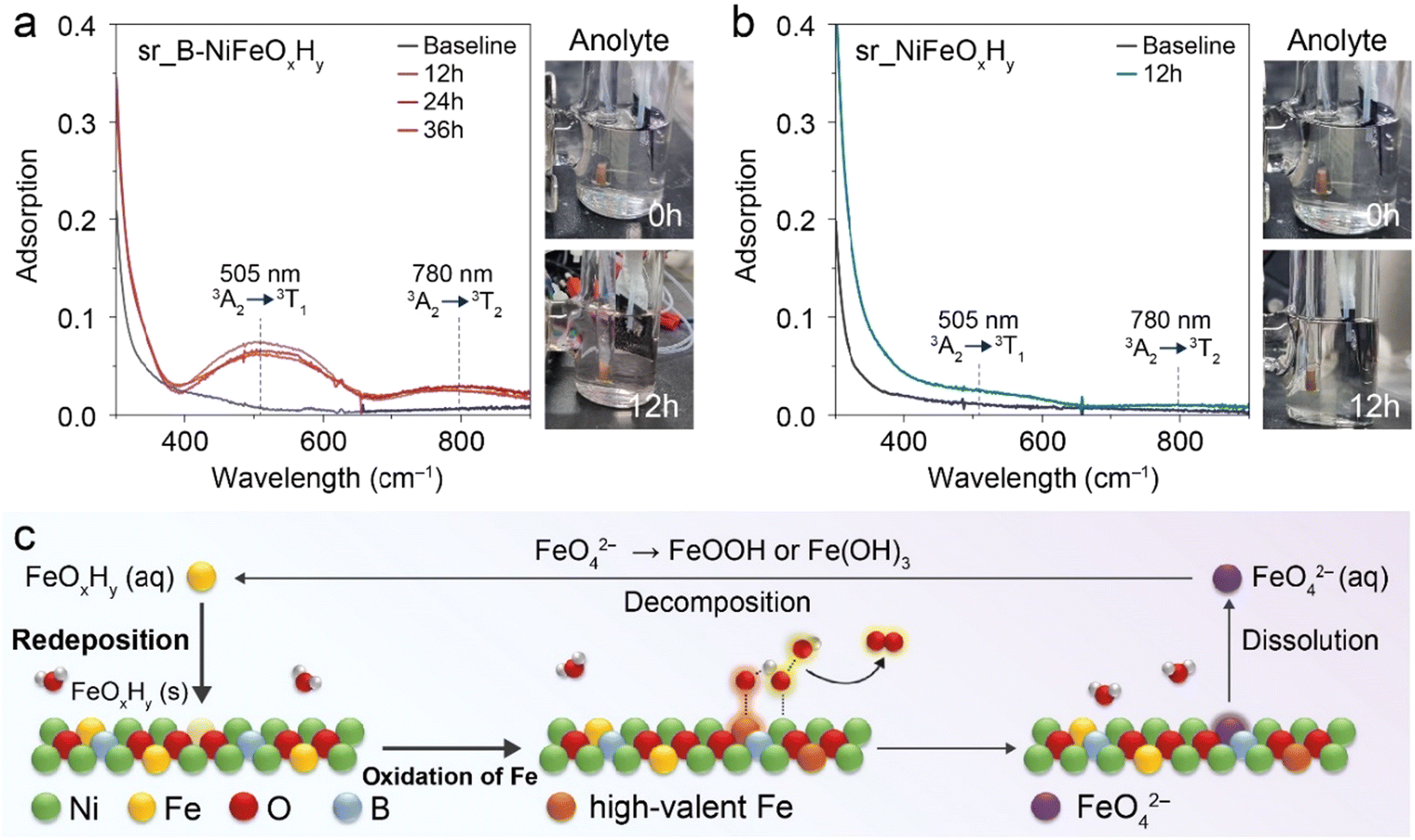 | ||
| Fig. 3 Detection of FeVIO42− species using in situ UV-vis spectroscopy of the anolyte during OER. (a) sr_B-NiFeOxHy, (b) sr_NiFeOxHy. (c) The proposed dissolution/redeposition mechanism for the high-valent Fe species in the sr_B-NiFeOxHy catalyst. | ||
To investigate the related electronic structure changes during OER, we conducted an in situ X-ray absorption near-edge structure (XANES) analysis of the Fe and Ni K-edge of sr_B-NiFeOxHy and sr_NiFeOxHy (Fig. S15 and S16†). Both sr_B-NiFeOxHy and sr_NiFeOxHy evolved into a higher oxidation state compared to their pristine counterparts. More specifically, in the Fe K-edge, the sr_B-NiFeOxHy went through an oxidation state change (Δ) of 2.0 eV whereas sr_NiFeOxHy only went through a 0.8 eV change. Likewise, the oxidation state difference of Ni between the pristine state and after applying potential was larger for sr_B-NiFeOxHy (1.1 eV) than sr_NiFeOxHy (0.9 eV), which was expected due to the surface reconstruction of the catalyst to the oxyhydroxide structure, seen in our previous operando Raman results. This reflects the hypothesis presented in Fig. 3 if higher quantities of Fe species are capable of oxidation during OER when boron is present, then a greater disparity would be observed between the pristine and the operando OER conditions. In addition, the oxidation state of Fe did not change after 1.43 V vs. RHE for sr_B-NiFeOxHy and 1.50 V vs. RHE for sr_NiFeOxHy, respectively, indicating that B induced a faster evolution of active Fe state on the catalyst surface allowing it to reach a steady state at a lower potential. To conclude, we investigated the Fe species and saw that B in NiFeOxHy induces a more feasible evolution of highly oxidized Fe species on the catalyst surface from the in situ XANES results and in situ UV-Vis analysis. From our results and previous literature that state the mechanism of Fe, we propose the effect of boron as Fig. 3c, to contribute additional improved activity of the catalyst through facilitating the catalytic active cycle of Fe including their dissolution and redeposition.
3.4. Stability of the catalyst
Alongside activity, the durability in high current densities is an important factor in evaluating an electrochemical catalyst.49 For NiFe catalysts, the previous reports have identified Fe segregation or Fe loss as the primary factor in the decline in catalytic activity during prolonged operation as the Fe inhomogeneity within the catalyst would induce changes in performance of the active sites.50,51 Consequently, it is important to observe the dynamic changes in Fe within the catalyst during long-term operations to gain insights into the stability of a catalyst. As results in Fig. 3c imply that boron facilitates the catalytic active cycle of Fe, we hypothesized that if the facilitated Fe cycle would prevent the accumulation of Fe segregation, a higher stability of the catalyst would be induced. To validate this hypothesis, a long-term stability test was conducted in a two-compartment H-cell to monitor the applied potential value at a high current density of 200 mA cm−2 (Fig. 4a). The activity of sr_NiFeOxHy began to decay rapidly after 3 h, and consequently endured for less than 12 h. On the contrary, sr_B-NiFeOxHy maintained the activity for 100 h, experiencing only a minuscule 50 mV change in potential. Sequentially, to assess the practicality of sr_B-NiFeOxHy, a long-term stability test was proceeded similar to industrial conditions for alkaline OER (55 °C in 30 wt% KOH) (Fig. S17†). The results revealed that boron incorporation leads to enhanced long-term stability, supported by the higher durability of the electrocatalysts with larger amounts of added boron. The stability of sr_B-NiFeOxHy surpasses those of recently reported catalysts (Fig. S18, S19 and Tables S2, †). | ||
| Fig. 4 (a) Long-term stability test of of sr_B-NiFeOxHy and sr_NiFeOxHy at a current density of 200 mA cm−2 and the corresponding inductively coupled plasma-mass spectrometry (ICP-MS) trace (b) sr_B-NiFeOxHy and (c) sr_NiFeOxHy during the long-term stability test. Electron probe micro-analysis (EPMA) of (d and e) sr_B-NiFeOxHy and (f and g) sr_NiFeOxHy for Ni and Fe after 10 and 12 hours at a current density of 200 mA cm−2, respectively. The highlighted areas indicate areas with similar Ni intensities. Orange and red boxes indicate Fe-poor regions and regions where Fe remained relatively intact, respectively. | ||
To examine whether the varying stabilities of the two catalysts originated from the substantial dissolution of metal elements from the catalyst surface, we measured the metal concentration in the electrolyte throughout the stability test using the ICP-MS. In addition to Fe, which is of interest due to its configuration being a main cause of decay in performance, Ni was also analyzed to not overlook the possibility of the degradation of the catalyst.52,53 Before all experiments, the as-prepared electrolytes had Fe and Ni concentrations of 59.9 ppb and 16.5 ppb, respectively, which was expected due to commercial KOH being known to contain metal impurities (Fig. 4b and c). After activation of the catalyst, the concentrations of Fe in the electrolyte diminished to 8.62 ppb for sr_B-NiFeOxHy and 35.7 ppb for sr_NiFeOxHy, due to the initial incorporation of Fe into the catalyst surface.12 In the course of the stability test, no noticeable increase in the concentration of either metal was observed in either electrolyte using B-NiFeOxHy or NiFeOxHy, indicating that stability loss was not attributable to metal leaching. Moreover, it is noteworthy that the average concentration of Fe throughout the stability test was lower for sr_B-NiFeOxHy (16.3 ppb) compared to sr_NiFeOxHy (31.4 ppb), indicating that the B-containing catalyst promoted the redeposition of Fe ions onto the catalyst surface and shifted the equilibrium at lower concentration values of Fe ions in the electrolyte (Fig. S20†). These results taken together with the in situ UV-Vis analysis, suggest that the introduction of boron promotes the formation/redeposition cycle of Fe species onto the catalyst surfaces, contributing to the enhanced OER activity.
To envision the spatial distribution of Fe relative to Ni on the catalyst, an electron probe microanalyzer (EPMA) was implemented before and after the stability test. Fig. 4d and f show that before the stability test, the relative intensities of Fe follow the intensities of Ni over the catalyst surface area, indicating the homogeneous distribution on the initial catalyst, consistent with the previously mentioned EDX mapping images. In sr_B-NiFeOxHy, after 12 h and 100 h of operation, there was no indication of inhomogeneous distribution of Fe (Fig. S21† and Fig. 4e). However, after 12 h of operation for sr_NiFeOxHy, we observed the Fe-poor areas, evident from the orange boxes that displayed a noticeable loss of Fe relative to Ni compared to the regions marked with red boxes, although all areas exhibited similar intensities of Ni (Fig. 4g). The Fe ions lost in this region might have redeposited in areas where Fe is present, making it challenging to identify an extremely segregated Fe site. Nevertheless, the findings still affirm that the absence of boron will result in an uneven distribution of Fe during OER, influencing the catalyst's performance in long-term operation.
To observe the local reconstruction of Fe with the OER stability test process, the Fe K-edge EXAFS spectrum for sr_B-NiFeOxHy was further analyzed. Fig. 5a demonstrates the EXAFS spectra of the pristine state, post 12 h and 100 h reaction of sr_B-NiFeOxHy. When compared with the pristine state, the increasing evolution of the Fe–M (M = Fe or Ni) radial distance at 2.70 Å is noticeably observed. This confirms the reconstruction of the Fe on the catalyst surface. If Fe is dissolved and redeposited on the catalyst surface, the local structure surrounding the Fe atom would vary, leading to consequential changes in the radial distances. A similar trend was seen in the radial distance of the Ni–M (M = Fe or Ni) bond of Ni K-edge EXAFS analysis drawn in Fig. 5b. The oxidation state variations of post-OER sr_B-NiFeOxHy were also examined by Fe and Ni K-edge XANES spectra. The Fe/Ni K-edges of post-12 h and 100 h sr_B-NiFeOxHy electrodes are shifted to a higher energy state by 1.5 (0.68) and 1.85 (0.83), respectively, compared to that of B-NiFeOxHy (Fig. S22 and S23†). In addition, the larger shifted value of Fe K-edge XANES spectra suggests the oxidation of Fe species during the long-term OER process. This analysis, along with the growth of distinct thin layers in the Cs-corrected STEM images of long-term post-OER sr_B-NiFeOxHy shown in Fig. S24,† confirms the active reconstruction of Fe and Ni on the B-NiFeOxHy catalyst during OER.44 Furthermore, to clarify the evolution of boron species and to determine whether boron had leached out from the catalyst, an XPS analysis of the electrodes after long-term stability was taken (Fig. 5c and Table S5†). After 12 h and 100 h of long-term operation, the M–B bond that was initially seen disappeared and only the boron–oxo bond continued to remain. The Ni:B ratio slightly diminished from 0.52 to 0.4 and 0.42 respectively. ICP-MS results further proved that the boron species retained on the catalyst after long-term operation, showing a Ni:B atomic ratio of 0.34 (Tables S6 and S7†). These results suggest that the boron species will modulate the active metal elements and prevent performance degradation as boron would remain within the catalyst.
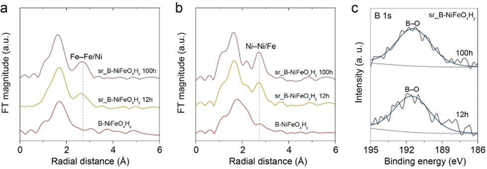 | ||
| Fig. 5 The normalized (a) Fe and (b) Ni K-edge EXAFS analyses of pristine B-NiFeOxHy, after 12 h (sr_B-NiFeOxHy 12 h) and 100 h (B-NiFeOxHy 100 h) of long-term stability. (c) The B 1s XPS spectra of sr_B-NiFeOxHy after 12 h and 100 h of long-term stability. | ||
Our B-incorporated catalyst demonstrated that the enhanced OER activity attributed to the incorporation of boron, which increased the production of high-valent Fe, and facilitated the regeneration cycle of Fe. This also prevented Fe inhomogeneity and mitigated activity degradation. These results imply that introducing boron and potentially other non-metal elements will induce changes in the dynamic cycle of Fe, leading to improvements in catalytic performance. Furthermore, we suggest the introduction of non-metal elements as a promising strategy for OER electrocatalysts and advise future studies to consider and monitor the dynamic processes and changes of Fe alongside Ni for the design of practical and efficient electrocatalysts.
4. Conclusions
In this study, we included boron in NiFe hydroxide using a chemical precipitation method and demonstrated its remarkable enhancement in OER activity, kinetics, and stability although the catalyst surfaces underwent reconstruction into NiOOH, irrespective of the presence of boron in NiFe catalysts. In-depth operando analysis revealed that the presence of boron in the catalyst facilitated more Fe to be oxidized compared to the B-free counterpart, evidenced by the increased production of FeO42− in the electrolyte and a more pronounced shift of the XANES Fe K-edge upon applying anodic potential. The redeposition of the Fe species was also enhanced. These results propose the contribution of boron in enhancing the activity of NiFe catalysts by facilitating the regeneration cycle of Fe. In addition, this allows the homogeneous distribution of Fe on the catalyst surface, improving the stability at high OER current density. Our proposed regeneration cycle was supported by the evolution of the Fe–Fe/Ni bond indicating the reconstruction of Fe on the catalyst surface. Our findings illuminate new perspectives on the effect of boron on regulating the activity of Fe and improving its stability. We believe our study provides insight into designing highly active and stable electrocatalysts for OER.Author contributions
Y. H. and J. C. contributed equally to this work. Y. Hong, J. Choi, and Y. J. Hwang designed the experiments. Y. Hong and J. Choi performed the electrochemical measurements and catalyst characterization. E. Lee, J. Choi, and Y. Hong performed and analyzed the X-ray adsorption spectroscopy data of the catalysts. Y. Hong, J. Choi, and Y. J. Hwang wrote the original draft.Conflicts of interest
There are no conflicts to declare.Acknowledgements
The acknowledgments come at the end of an article after the conclusions and before the notes and references. This work was supported by the National Research Foundation of Korea (NRF) grant funded by the Korea government (2021M3H4A1A03057403, 2021R1A5A1084921, 2022R1A2B5B02001380). The authors also acknowledge the financial support by the Creative-Pioneering Researchers Program and the New Faculty Startup Fund from Seoul National University. This work was supported by the LAMP Program of the National Research Foundation of Korea (NRF) grant funded by the Ministry of Education (No. RS-2023-00301976).References
- C. Wan, Z. Zhang, J. Dong, M. Xu, H. Pu, D. Baumann, Z. Lin, S. Wang, J. Huang and A. H. Shah, Nat. Mater., 2023, 1–8 Search PubMed.
- C. Cai, K. Liu, Y. Zhu, P. Li, Q. Wang, B. Liu, S. Chen, H. Li, L. Zhu and H. Li, Angew. Chem., Int. Ed., 2022, 61, e202113664 CrossRef CAS PubMed.
- J. H. Kim, H. Jang, G. Bak, W. Choi, H. Yun, E. Lee, D. Kim, J. Kim, S. Y. Lee and Y. J. Hwang, Energy Environ. Sci., 2022, 15, 4301–4312 RSC.
- M. Kolen, D. Ripepi, W. A. Smith, T. Burdyny and F. M. Mulder, ACS Catal., 2022, 12, 5726–5735 CrossRef CAS PubMed.
- C. Wang, P. Zhai, M. Xia, Y. Wu, B. Zhang, Z. Li, L. Ran, J. Gao, X. Zhang and Z. Fan, Angew. Chem., Int. Ed., 2021, 60, 27126–27134 CrossRef CAS PubMed.
- L. Dai, Z. N. Chen, L. Li, P. Yin, Z. Liu and H. Zhang, Adv. Mater., 2020, 32, 1906915 CrossRef CAS PubMed.
- F. Song, L. Bai, A. Moysiadou, S. Lee, C. Hu, L. Liardet and X. Hu, J. Am. Chem. Soc., 2018, 140, 7748–7759 CrossRef CAS PubMed.
- C. C. McCrory, S. Jung, J. C. Peters and T. F. Jaramillo, J. Am. Chem. Soc., 2013, 135, 16977–16987 CrossRef CAS PubMed.
- S. Zhou, H. He, J. Li, Z. Ye, Z. Liu, J. Shi, Y. Hu and W. Cai, Adv. Funct. Mater., 2023, 2313770 Search PubMed.
- M. H. Wang, Z. X. Lou, X. Wu, Y. Liu, J. Y. Zhao, K. Z. Sun, W. X. Li, J. Chen, H. Y. Yuan and M. Zhu, Small, 2022, 18, 2200303 CrossRef CAS PubMed.
- R. Chen, S.-F. Hung, D. Zhou, J. Gao, C. Yang, H. Tao, H. B. Yang, L. Zhang, L. Zhang, Q. Xiong, H. M. Chen and B. Liu, Adv. Mater., 2019, 31, 1903909 CrossRef CAS PubMed.
- L. Trotochaud, S. L. Young, J. K. Ranney and S. W. Boettcher, J. Am. Chem. Soc., 2014, 136, 6744–6753 CrossRef CAS PubMed.
- Z. Qiu, Y. Ma and T. Edvinsson, Nano Energy, 2019, 66, 104118 CrossRef CAS.
- N. Li, D. K. Bediako, R. G. Hadt, D. Hayes, T. J. Kempa, F. Von Cube, D. C. Bell, L. X. Chen and D. G. Nocera, Proc. Natl. Acad. Sci. U. S. A., 2017, 114, 1486–1491 CrossRef CAS PubMed.
- Z. Zhang, C. Wang, X. Ma, F. Liu, H. Xiao, J. Zhang, Z. Lin and Z. Hao, Small, 2021, 17, 2103785 CrossRef CAS PubMed.
- D. Friebel, M. W. Louie, M. Bajdich, K. E. Sanwald, Y. Cai, A. M. Wise, M.-J. Cheng, D. Sokaras, T.-C. Weng and R. Alonso-Mori, J. Am. Chem. Soc., 2015, 137, 1305–1313 CrossRef CAS PubMed.
- J. Y. Chen, L. Dang, H. Liang, W. Bi, J. B. Gerken, S. Jin, E. E. Alp and S. S. Stahl, J. Am. Chem. Soc., 2015, 137, 15090–15093 CrossRef CAS PubMed.
- H. S. Ahn and A. J. Bard, J. Am. Chem. Soc., 2016, 138, 313–318 CrossRef CAS PubMed.
- B. M. Hunter, N. B. Thompson, A. M. Müller, G. R. Rossman, M. G. Hill, J. R. Winkler and H. B. Gray, Joule, 2018, 2, 747–763 CrossRef CAS.
- D. Y. Chung, P. P. Lopes, P. Farinazzo Bergamo Dias Martins, H. He, T. Kawaguchi, P. Zapol, H. You, D. Tripkovic, D. Strmcnik and Y. Zhu, Nat. Energy, 2020, 5, 222–230 CrossRef.
- D. Tyndall, M. J. Craig, L. Gannon, C. McGuinness, N. McEvoy, A. Roy, M. García-Melchor, M. P. Browne and V. Nicolosi, J. Mater. Chem. A, 2023, 11, 4067–4077 RSC.
- R.-Y. Fan, J.-Y. Xie, H.-J. Liu, H.-Y. Wang, M.-X. Li, N. Yu, R.-N. Luan, Y.-M. Chai and B. Dong, Chem. Eng. J., 2022, 431, 134040 CrossRef CAS.
- Q. Xu, H. Jiang, X. Duan, Z. Jiang, Y. Hu, S. W. Boettcher, W. Zhang, S. Guo and C. Li, Nano Lett., 2020, 21, 492–499 CrossRef PubMed.
- P. Yan, Q. Liu, H. Zhang, L. Qiu, H. B. Wu and X.-Y. Yu, J. Mater. Chem. A, 2021, 9, 15586–15594 RSC.
- T. Chen, B. Li, K. Song, C. Wang, J. Ding, E. Liu, B. Chen and F. He, J. Mater. Chem. A, 2022, 10, 22750–22759 RSC.
- J. Xie, F. Wang, Y. Zhou, Y. Dong, Y. Chai and B. Dong, Nano-Micro Lett., 2023, 16, 39 CrossRef PubMed.
- K. Chen, Y.-H. Cao, S. Yadav, G.-C. Kim, Z. Han, W. Wang, W.-J. Zhang, V. Dao and I.-H. Lee, Chem. Eng. J., 2023, 463, 142396 CrossRef CAS.
- Y. Mu, Y. Zhang, Z. Feng, X. Dong, X. Jing, X. Pei, Y. Zhao, Z. Kou and C. Meng, Chem. Eng. J., 2023, 460, 141709 CrossRef CAS.
- H. Liao, G. Ni, P. Tan, K. Liu, X. Liu, H. Liu, K. Chen, X. Zheng, M. Liu and J. Pan, Adv. Mater., 2023, 35, 2300347 CrossRef CAS PubMed.
- Y. Bai, Y. Wu, X. Zhou, Y. Ye, K. Nie, J. Wang, M. Xie, Z. Zhang, Z. Liu and T. Cheng, Nat. Commun., 2022, 13, 6094 CrossRef CAS PubMed.
- N. Wang, A. Xu, P. Ou, S.-F. Hung, A. Ozden, Y.-R. Lu, J. Abed, Z. Wang, Y. Yan and M.-J. Sun, Nat. Commun., 2021, 12, 6089 CrossRef CAS PubMed.
- W. Hao, D. Yao, Q. Xu, R. Wang, C. Zhang, Y. Guo, R. Sun, M. Huang and Z. Chen, Appl. Catal. B, 2021, 292, 120188 CrossRef CAS.
- C. Feng, X. She, Y. Xiao and Y. Li, Angew. Chem., Int. Ed., 2023, 62, e202218738 CrossRef CAS PubMed.
- M. Mehdi, B.-S. An, H. Kim, S. Lee, C. Lee, M. Seo, M. W. Noh, W.-C. Cho, C.-H. Kim, C. H. Choi, B.-H. Kim, M. Kim and H.-S. Cho, Adv. Energy Mater., 2023, 13, 2204403 CrossRef CAS.
- C. Zhang, M. Shao, L. Zhou, Z. Li, K. Xiao and M. Wei, ACS Appl. Mater. Interfaces, 2016, 8, 33697–33703 CrossRef CAS PubMed.
- C. Tang, H.-F. Wang, H.-S. Wang, F. Wei and Q. Zhang, J. Mater. Chem. A, 2016, 4, 3210–3216 RSC.
- C. Hu, Y. Hu, C. Fan, L. Yang, Y. Zhang, H. Li and W. Xie, Angew. Chem., Int. Ed., 2021, 60, 19774–19778 CrossRef CAS PubMed.
- W. Jiang, A. Y. Faid, B. F. Gomes, I. Galkina, L. Xia, C. M. S. Lobo, M. Desmau, P. Borowski, H. Hartmann, A. Maljusch, A. Besmehn, C. Roth, S. Sunde, W. Lehnert and M. Shviro, Adv. Funct. Mater., 2022, 32, 2203520 CrossRef CAS.
- J. Masa, I. Sinev, H. Mistry, E. Ventosa, M. de la Mata, J. Arbiol, M. Muhler, B. Roldán Cuenya and W. Schuhmann, Adv. Energy Mater., 2017, 7, 1700381 CrossRef.
- C. Qiang, L. Zhang, H. He, Y. Liu, Y. Zhao, T. Sheng, S. Liu, X. Wu and Z. Fang, J. Colloid Interface Sci., 2021, 604, 650–659 CrossRef CAS PubMed.
- Y. Tang, Q. Liu, L. Dong, H. B. Wu and X.-Y. Yu, Appl. Catal., B, 2020, 266, 118627 CrossRef CAS.
- J. Choi, D. Kim, W. Zheng, B. Yan, Y. Li, L. Y. S. Lee and Y. Piao, Appl. Catal., B, 2021, 286, 119857 CrossRef CAS.
- C. Cao, D.-D. Ma, Q. Xu, X.-T. Wu and Q.-L. Zhu, Adv. Funct. Mater., 2019, 29, 1807418 CrossRef.
- D. Kim, S. Park, J. Choi, Y. Piao and L. Y. S. Lee, Small, 2023, 2304822 Search PubMed.
- H. Shin, H. Xiao and W. A. Goddard III, J. Am. Chem. Soc., 2018, 140, 6745–6748 CrossRef CAS PubMed.
- C. Feng, F. Wang, Z. Liu, M. Nakabayashi, Y. Xiao, Q. Zeng, J. Fu, Q. Wu, C. Cui and Y. Han, Nat. Commun., 2021, 12, 5980 CrossRef CAS PubMed.
- S. Licht and X. Yu, Environ. Sci. Technol., 2005, 39, 8071–8076 CrossRef CAS PubMed.
- S. Licht, B. Wang and S. Ghosh, Science, 1999, 285, 1039–1042 CrossRef CAS PubMed.
- F.-Y. Chen, Z.-Y. Wu, Z. Adler and H. Wang, Joule, 2021, 5, 1704–1731 CrossRef CAS.
- M. Cai, Q. Zhu, X. Wang, Z. Shao, L. Yao, H. Zeng, X. Wu, J. Chen, K. Huang and S. Feng, Adv. Mater., 2023, 35, 2209338 CrossRef CAS PubMed.
- S.-Y. Lee, H.-J. Oh, M. Kim, H.-S. Cho and Y.-K. Lee, Appl. Catal., B, 2023, 324, 122269 CrossRef CAS.
- S. H. Chang, N. Danilovic, K.-C. Chang, R. Subbaraman, A. P. Paulikas, D. D. Fong, M. J. Highland, P. M. Baldo, V. R. Stamenkovic, J. W. Freeland, J. A. Eastman and N. M. Markovic, Nat. Commun., 2014, 5, 4191 CrossRef CAS PubMed.
- T. Binninger, R. Mohamed, K. Waltar, E. Fabbri, P. Levecque, R. Kötz and T. J. Schmidt, Sci. Rep., 2015, 5, 12167 CrossRef CAS PubMed.
Footnotes |
| † Electronic supplementary information (ESI) available. See DOI: https://doi.org/10.1039/d4nr01186d |
| ‡ These authors equally contributed to this work. |
| This journal is © The Royal Society of Chemistry 2024 |