
 Open Access Article
 This Open Access Article is licensed under a
 Creative Commons Attribution 3.0 Unported Licence
An efficient titanomaghemite MOF-derived catalyst for reverse water–gas shift†
Orxan
Sayidov
 a,
Luis
Garzon-Tovar
a,
Javier
Patarroyo
b,
Giiaz
Bekmukhamedov
b,
Joseph A.
Stewart
c,
Bart D.
Vandegehuchte
c,
Nicolas
Montroussier
d,
Javier
Ruiz-Martinez
b and
Jorge
Gascon
*a
a,
Luis
Garzon-Tovar
a,
Javier
Patarroyo
b,
Giiaz
Bekmukhamedov
b,
Joseph A.
Stewart
c,
Bart D.
Vandegehuchte
c,
Nicolas
Montroussier
d,
Javier
Ruiz-Martinez
b and
Jorge
Gascon
*a
aAdvanced Catalytic Materials (ACM), KAUST Catalysis Center (KCC), King Abdullah University of Science and Technology (KAUST), Thuwal 23955-6900, Saudi Arabia. E-mail: jorge.gascon@kaust.edu.sa
bKAUST Catalysis Center, King Abdullah University of Science and Technology, Jeddah, Saudi Arabia
cTotal Energies OneTech Belgium, Zone Industrielle Feluy C, Seneffe, 7181, Belgium
dTotalEnergies OneTech, Tour Coupole, 2 place Jean Millier, La Défense 6, 92078, Paris La Défense Cedex, France
First published on 18th March 2025
Abstract
In response to the escalating greenhouse gas (GHG) emission crisis, integrating the reverse water–gas shift (RWGS) reaction with Fischer–Tropsch synthesis (FTS) has been identified as a promising two-step approach for converting CO2 and H2 into valuable products. However, the requirement for high temperatures to achieve significant CO2 conversion, along with the formation of undesired products (e.g., methane) at high pressures during the RWGS step, presents challenges for integrating the RWGS reaction with FTS synthesis. In this context, developing a low-temperature RWGS catalyst that can suppress CO2 methanation, even under high pressure, is paramount for facilitating energy integration between the two processes. In this study, we present an in-depth study of a metal–organic framework (MOF)-derived solid as a catalyst for the low temperature RWGS reaction. Our catalyst showed high activity and stability, achieving up to 97% CO selectivity at close to equilibrium CO2 conversion levels at moderate temperatures and high pressures. A kinetic study of the resulting titanomaghemite catalyst was conducted to determine the kinetic parameters that describe the catalytic system and to facilitate future reactor and process design.
1. Introduction
Amid rising concerns about greenhouse gas (GHG) emissions, carbon dioxide (CO2) emissions stand as one of the most crucial global problems, totaling 36.8 Gt in 2022.1 So far, two main strategies have been proposed for the mitigation of CO2 emissions: (i) carbon dioxide capture and storage (CCS) and (ii) carbon dioxide capture and utilization (CCU), where CO2 is used as a feedstock for chemicals and fuels.2–4 Although, given the large amounts of CO2 emitted, CCS will be necessary, recycling of carbon dioxide through CCU is very attractive, especially to help decarbonize certain sectors of the economy. Particularly, one of the CCU strategies is the direct hydrogenation of CO2 through a process similar to the Fischer–Tropsch synthesis (FTS) process, which is a viable alternative for converting CO2 into valuable chemicals and fuels.5–8 However, controlling the product distribution, specifically minimizing methane formation, remains a challenge.9–11 On the other hand, combining the reverse water–gas shift reaction (RWGS, eqn (1)) with FT synthesis (eqn (2)) is a promising approach to convert in two steps CO2 and H2 into valuable products, including alcohols, aromatics, olefins, and fuels.12–15| CO2 + H2 ⇌ CO + H2O ΔH0 = 41.2 kJ mol−1 | (1) |
| CO + 2H2 ⇌ (−CH2−) + H2O ΔH0 = −152 kJ mol−1 | (2) |
The RWGS reaction is thermodynamically favorable at high temperatures (>700 °C); however, at low temperatures, exothermic reactions such as CO2 methanation (Sabatier), methanol production, and CO methanation are favored. This prevents higher CO production at moderate temperatures (eqn (3)–(5)).16,17 As a consequence, the RWGS reaction needs to be conducted at elevated temperatures to achieve high CO2 conversions, which creates a temperature gap when coupled with an FTS unit (200–400 °C).
| CO2 + 4H2 ⇌ CH4 + 2H2O ΔH0 = −165 kJ mol−1 | (3) |
| CO + 3H2 ⇌ CH4 + H2O ΔH0 = −206 kJ mol−1 | (4) |
| CO2 + 3H2 ⇌ CH3OH + H2O ΔH0 = −49.8 kJ mol−1 | (5) |
Likewise, operating at elevated temperatures compromises the durability of both the catalyst and the reactor, leading to reduced operational lifespans. Furthermore, at high temperatures, potential issues such as catalyst coking, attrition, and the sintering of active metal sites can be anticipated.16,18 Another critical point for harmonizing the RWGS and FTS reactions, and making the process efficient, is that the pressure of both systems should be similar (around 20 bar). However, at high pressure, methane becomes a preferred product.19 In this context, designing a low-temperature RWGS catalyst that suppresses CO2 methanation, even at high pressures, is crucial for facilitating overall energy integration in the RWGS–FTS process. For example, Juneau et al. reported a potassium-promoted molybdenum carbide catalyst that effectively catalyzed the RWGS reaction at temperatures up to 450 °C and 20 bar, achieving 100% CO selectivity.20 Similarly, Barberis et al. recently developed an alkali-promoted copper-based catalyst that demonstrated high CO2 conversion levels and nearly 100% CO selectivity at low temperatures (180–260 °C) and high pressures (20–40 bar).21 Although most research has focused on the development of noble metal catalysts due to their high selectivity towards carbon monoxide,22–31 there is growing interest in using inexpensive non-noble metals.32–48 In particular, iron oxides have attracted attention as cost-effective and promising catalysts for the RWGS process. However, at high temperatures in the presence of syngas, the formation of iron carbide becomes a prominent issue, ultimately leading to enhanced methanation and subsequent catalyst deactivation.49 Recently, Castells-Gil et al. highlighted the advantages of forming mixed oxides based on the Fe–Ti–O system. Specifically, they demonstrated that the substitution of Fe by Ti ions in the α-Fe2O3 structure stabilizes the oxidic form of iron, preventing its reduction to metallic iron and the subsequent formation of iron carbides. Additionally, they showed that iron plays a key role in CO2 activation by providing surface vacancies sites for CO2 adsorption, thereby promoting its direct hydrogenation to CO through the formation of a COOH* intermediate.18 They synthesized carbon-supported titanomaghemite nanoparticles through the thermal decomposition of a metal–organic framework (MOF) known as MUV-101 [TiFe2O(X)3(benzene-1,3,5-tricarboxylate)2 (X = OH–, O2−, H2O)]. They found that the Fe/Ti nodes in the MOF play an important role in ensuring the uniform integration of titanium into the titanomaghemite spinel structure. Interestingly, the resulting titanomaghemite phase exhibits an unprecedented Fe/Ti ratio close to 2, which is not achievable through traditional soft-chemistry routes. Moreover, the nanoparticles demonstrated outstanding catalytic activity for the production of CO from CO2, achieving a CO selectivity of approximately 100% even at a high pressure of 30 bar, which is significantly higher compared to other Fe/C, [Fe + Ti]/C, and TiO2@Fe3O4 catalysts.18 Despite the promising performance of the MUV-101-derived catalyst, the high cost associated with the ligand limits its scalability for practical applications.
In this work, we report the synthesis of a new heterometallic Fe/Ti-based MOF (MIL-88B (Fe,Ti)) using a cost-effective linker (1,4-benzene dicarboxylic acid). Recently, we demonstrated that the presence of steam during the pyrolysis of MOFs (steam pyrolysis process) helps to control the phase composition of the catalyst, decrease the particle size of the resulting nanoparticles, and improve their crystallinity. This leads to more efficient catalysts compared with those produced by conventional pyrolysis.50 Based on this, the synthesis of the carbon-supported titanomaghemite catalyst was performed through the thermal decomposition of the new MIL-88B (Fe, Ti) using the steam pyrolysis approach. As mentioned above, the presence of both iron and titanium in the oxo-clusters of MIL-88 (Fe, Ti) favors the uniform integration of titanium into the titanomaghemite spinel structure. The optimized catalyst demonstrated high activity and stability for the RWGS reaction, achieving up to 97% CO selectivity with equilibrium CO2 conversion levels at moderate temperatures and high pressure. Lastly, we conducted a kinetic study using the model proposed by Hou and Hughes to estimate the rate and adsorption constants. An R2 value of 0.9921 validates the model, which describes the RWGS reaction over the titanomaghemite catalyst and the factors affecting CO formation rates.
2. Experimental
2.1. Materials and reagents
Anhydrous iron(II) chloride (FeCl2), benzene-1,4-dicarboxylic acid (BDC), titanium isopropoxide (TTIP), anhydrous N,N-dimethylformamide (DMF), and propanol-2 (IPA) were purchased from Sigma-Aldrich (Merck), whereas glacial acetic acid and ethanol were purchased from Fisher Scientific. Before their use in the synthesis, DMF, IPA, and acetic acid were degassed by the freeze–pump–thaw method. The other reagents were used without any additional purification steps.2.2. Materials preparation
![[thin space (1/6-em)]](https://www.rsc.org/images/entities/char_2009.gif) mL min−1) and heated at different temperatures (550, 600, and 700 °C) for 7 or 4 h using a heating ramp of 2°C min−1. After cooling down of the reactor, the sample was passivated in a continuous flow of air (10mL min−1) for 2 hours.
mL min−1) and heated at different temperatures (550, 600, and 700 °C) for 7 or 4 h using a heating ramp of 2°C min−1. After cooling down of the reactor, the sample was passivated in a continuous flow of air (10mL min−1) for 2 hours.
2.3. Catalyst characterization
Powder X-ray diffraction (PXRD) analyses were carried out using a Bruker D8 Advanced diffractometer configured in the Bragg–Brentano geometry fitted with a copper tube operating at 40 kV and 40 mA. The diffractograms for the MOF-derived materials were acquired over a 2θ range of 10–90°, employing a step size of 0.2° with a time per step of 8 seconds. The diffractograms for MIL-88B (Fe,Ti) were acquired over a 2θ range of 4–40°, employing a step size of 0.018° with a time per step of 1 second. The crystalline phases were identified by comparison data from the Powder Diffraction File PDF-4.51Scanning electron microscopy (SEM) images were recorded using a Zeiss Merlin scanning electron microscope (SEM), which operated at a constant acceleration voltage of 3 kV and an emission current of 2 nA. The SEM equipped with an energy-dispersive X-ray spectroscopy (EDX) detector (Oxford Instruments) was used for elemental mapping.
N2 adsorption–desorption measurements were performed at 77 K using a Micromeritics ASAP 2040 instrument. Before measurements, the samples were degassed at 120 °C for 12 h under vacuum.
Thermogravimetric (TG) data were collected under a nitrogen atmosphere using a Mettler-Toledo thermal analyzer at a heating rate of 5 °C min−1 in the 25–700 °C temperature range and a gas flow of 25 mL min−1 for MIL-88B (Fe,Ti). For the MOF-derived materials, the thermal decomposition was performed in an air atmosphere under the conditions described above.
Temperature programmed reduction (TPR) coupled with mass spectroscopy (MS) was conducted using a Micromeritics AutoChem 2920 combined with an MKS Cirrus 3. Firstly, the sample (50 mg) was placed in a U-tube quartz reactor and pretreated (5 °C min−1) in an Ar flow at 120 °C for 30 min. Subsequently, the gas flow was switched to a 10% H2/Ar flow at a rate of 50 mL min−1. The heating ramp was set at 10 °C min−1 up to 600 °C. A thermal conductivity detector (TCD) was employed to monitor the H2 consumption process.
X-ray photoelectron spectroscopy (XPS) measurements were performed using a Kratos/Shimadzu Amicus equipped with dual Mg/Al anodes and a single channeltron detector. The XPS spectra of the samples were acquired at a base pressure of 3 × 10⁻⁷ Pa using an Al anode at a fixed analyzed pass energy of E = 150 eV. Binding energies were referenced to the sp2 hybridized (C![[double bond, length as m-dash]](https://www.rsc.org/images/entities/char_e001.gif) C) carbon for the C 1s peak set at 284.4 eV. The data were analyzed using CasaXPS software (version 2.3.16).
C) carbon for the C 1s peak set at 284.4 eV. The data were analyzed using CasaXPS software (version 2.3.16).
Raman spectra were recorded using a confocal Raman microscope WITec Apyron equipped with a 532 nm laser with a power of 0.5 mW. An objective Zeiss LD EC Epiplan-Neofluar Dic 50×/0.55 was used to collect Raman spectra with an integration time of 0.5 s and an accumulation number of 20. Raman spectra from different locations were collected for each sample.
High-angle annular dark-field scanning transmission electron microscopy (HAADF-STEM) images, coupled with energy dispersive X-ray spectroscopy (EDS), were obtained using a Cs-probe corrected Titan microscope from Thermo Fisher Scientific, operating at an accelerating voltage of 300 kV. Imaging and spectroscopy data sets were acquired and analyzed with the Velox software package, also from Thermo Fisher Scientific. The generated maps underwent minor post-filtering through the application of a Gaussian filter with a sigma value of 0.8.
Transmission electron microscopy (TEM) of the samples was performed with a Titan ST microscope from Thermo Fisher Scientific operating at an accelerating voltage of 300 kV. For each sample, the size of at least 150 particles was measured and the average size and the standard distribution were obtained.
2.4. Catalytic tests
Catalytic tests were conducted using an Avantium 4-channel Flowrence unit, and in each experiment, the first reactor was used as a blank for subsequent calculations. Catalysts were reduced in the presence of an H2/CO2 = 5 mixture for 4 hours at 425 °C and at atmospheric pressure. Subsequently, the reactors were pressurized stepwise in the 15–50 bar range, and then a feed mixture with an H2/CO2 = 3 ratio was introduced into the reactors. The flow rate of this mixture varied depending on the desired gas hourly space velocity (GHSV), which ranged from 6000 to 24000 mL gcat−1 h−1. The effect of the feed H2/CO2 ratio was also studied in the 1–4 range. In each analysis, an 8 vol% helium (He) flow was included in the feed mixture as an internal standard. The reactor tubes are made of stainless steel, with an inner diameter of 2 mm and a length of 300 mm. To ensure that the catalyst remained in the isothermal zone of the furnace, the reactors were initially loaded with 0.2 mL of silicon carbide particles (100 μm particle size). The pressurization system employed a membrane-based controller, regulated by the flow of diluent nitrogen (N2). For each change in reaction conditions, 10 minutes were allowed for stabilization.
The CO2 conversion (XCO2, %), product selectivity (Sy, %) and space time yield of CO (STYCO, mmolCO gcat−1 h−1) were calculated using the equations below (eqn (6)–(8)):
 | (6) |
 | (7) |
 | (8) |
3. Results and discussion
3.1. Synthesis and characterization of MIL-88B (Fe,Ti) and FeTi@C materials
To synthesize the new heterometallic MIL-88B (Fe,Ti), a solvothermal reaction was performed using FeCl2, titanium(IV) isopropoxide, and terephthalic acid (BDC) in an N,N-dimethylformamide (DMF)/isopropanol solution in the presence of acetic acid as a modulator. After 24 h of reaction, brownish rods and octahedral-shaped crystals were isolated (Fig. 1b). The phase purity of MIL-88B (Fe,Ti) was confirmed by matching the experimental powder X-ray diffraction (PXRD) pattern with the simulated pattern of the monometallic MIL-88B-Fe (Fig. 1a).52 Scanning electron microscopy (SEM) further confirmed the formation of octahedral- and rod-shaped crystals with heterogeneous size distribution, while energy dispersive X-ray spectrometry (EDX) elemental mapping revealed a homogeneous distribution of Fe and Ti, consistent with the expected Fe:Ti molar ratio of 2:1 (Fig. 1c and Fig. S1†). The thermal stability of MIL-88B (Fe,Ti) was evaluated using thermogravimetric analysis (TGA), which revealed that the material maintained its crystallinity up to 450 °C (Fig. S2†). Complete decomposition of the framework occurred at 500 °C. Similar to the isoreticular MIL-88B-type solids, MIL-88B (Fe,Ti) is non-porous in its dried, contracted form, as confirmed by nitrogen adsorption–desorption measurements (Fig. S3†).53–56
 | ||
| Fig. 1 a) PXRD pattern of MIL-88B (Fe,Ti) powder (red), as compared to the corresponding simulated powder pattern (blue). b) SEM images of MIL-88B (Fe,Ti) showing the heterogeneous particle size distribution. c) SEM and EDS mapping images showing the distribution of Fe and Ti throughout the rod-shaped MIL-88B (Fe,Ti) crystal. | ||
Next, the pyrolysis of MIL-88B (Fe,Ti) was carried out at 550, 600, and 700 °C for 7 hours under an N2/H2O atmosphere. Initially, a steam partial pressure of 3.13 kPa was fixed by setting the bubbler temperature to 25 °C. The resulting samples are denoted as FeTi@C550-25, FeTi@C600-25, and FeTi@C700-25, where the first number represents the pyrolysis temperature and the second the bubbler temperature. PXRD analysis revealed that titanomaghemite (Fe2TiO4) was obtained as a pure phase during steam pyrolysis at 550 °C. However, during pyrolysis at 600 and 700 °C, a mixture of Fe2TiO4 and ilmenite (FeTiO3) was observed (Fig. S4†). We hypothesize that the presence of ilmenite may be due to the inversion of the metastable titanomaghemite spinel structure, which increases with higher pyrolysis temperatures.57 In addition, N2 adsorption measurements revealed that increasing the steam-pyrolysis temperature up to 700 °C led to a significant reduction in porosity compared to the materials steam-pyrolyzed at 550 and 600 °C. The BET surface area was reduced from 73–107 m2 g−1 to 22 m2 g−1 (Fig. S5†). After determining the optimal pyrolysis temperature, we investigated the influence of steam pressure during the pyrolysis. Similarly, we steam pyrolyzed MIL-88B (Fe,Ti) at 550 °C and at steam partial pressures of 0.86, 3.13, and 7.28 kPa (corresponding to bubbler temperatures of 5, 25, and 40 °C, respectively). The PXRD patterns of FeTi@C550-5, FeTi@C550-25, and FeTi@C550-40 indicate that the steam content does not affect the final phase composition, as Fe2TiO4 is the only crystalline phase formed during pyrolysis (Fig. S6†). Transmission electron microscopy (TEM) and high-angle annular dark-field scanning transmission electron microscopy (HAADF-STEM) images revealed that the FeTi@C550-X solids consist of titanomaghemite nanoparticles, which are highly dispersed within a carbon matrix and have an average particle size of 5 nm (Fig. S7–S9†). Elemental analysis by STEM-EDX shows a homogeneous distribution of Fe and Ti (Fig. 2), and inductively coupled plasma optical emission spectroscopy (ICP-OES) analysis confirms the atomic Fe/Ti ratio of ∼2 (Table S1†). Next, we performed thermogravimetric analysis (TGA) in air to determine the carbon content in the FeTi@C550-X solids. From the TGA curves, carbon contents of 20% (FeTi@C550-5), 9% (FeTi@C550-25), and 6% (FeTi@C550-40) were calculated (Fig. S10†). These results confirm the partial gasification of carbon treated under the steam-pyrolysis, which increases with the steam partial pressure. Indeed, N2 adsorption analyses are consistent with the TGA results, showing a slight decrease in the BET-specific surface areas with carbon content decreases of 125, 73, and 63 m2 g−1 for FeTi@C550-5, FeTi@C550-25, and FeTi@C550-40, respectively (Fig. S11†). Subsequently, the graphitization degree of the carbon matrix was studied by Raman spectroscopy. The Raman spectra of all the catalysts displayed two characteristic peaks at 1360 and 1590 cm−1 (Fig. S12†). The first peak is a disorder-induced band (D band), characteristic of amorphous or defect graphite, and originates from the double resonance Raman process for sp2 carbon.58 The latter peak is assigned to the E2g mode of the infinite graphite crystal (G band).58,59 The intensity ratio of the two bands (IG/ID) was used to evaluate the graphitization degree of the different solids. Interestingly, we found that the values of the IG/ID ratio are similar across all catalysts (1.27–1.33), suggesting the same degree of graphitization. The surface of the FeTi@C550-X materials was investigated by X-ray photoelectron spectroscopy (XPS). The Fe 2p core level spectra consist of two main peaks at approximately 711 eV and 725 eV, corresponding to the 2p3/2 and 2p1/2 spin–orbital splitting photoelectrons of Fe3+, as well as their shake-up satellites at approximately 718 eV and 733 eV, respectively (Fig. S13†).60,61 No Fe0 and Fe2+ peaks were observed in the spectra, suggesting the presence of Fe2+ metal vacancies, which is in agreement with previously reported work. Additionally, these results allow us to approximate the expected structural formula of titanomaghemite as: Fe3+[Fe3+0.7Ti4+0.7⊡0.6]O2−4 (see eqn (S1) and (S2)†)18 The Ti 2p XPS spectra were deconvoluted into two main peaks (2p3/2 and 2p1/2) located at approximately 458 eV and 463 eV, corresponding to titanium in the oxidation state 4+ (Fig. S14†).62,63 The C 1s core level spectra were fitted with three components, located at approximately 284, 285, and 287 eV, ascribed to the CC (sp2), C–O, and O–CO bonds, respectively (Fig. S15†). The O 1s spectra were deconvoluted into three peaks located at 529, 531, and 533 eV, corresponding to the M–O–M, M–OH, and M–H2O/CO bonds, respectively (Fig. S16†).18
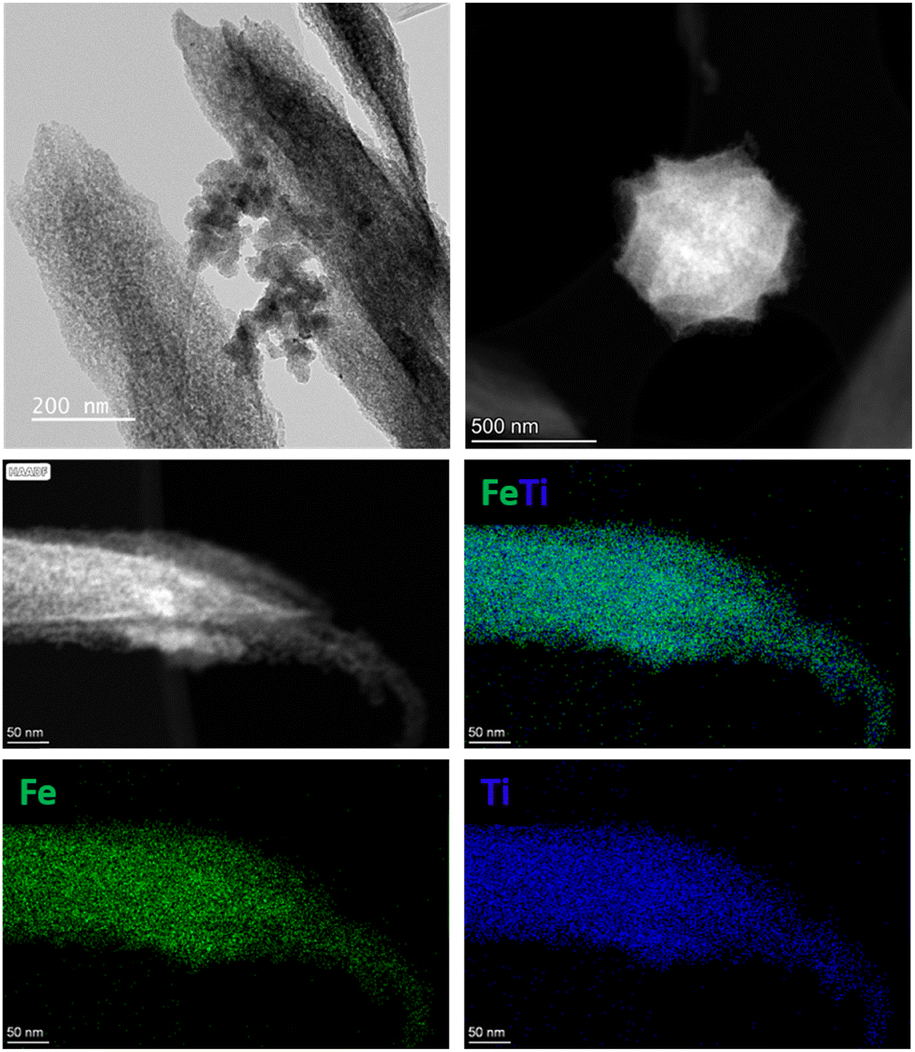 | ||
| Fig. 2 TEM, HAADF-STEM, and elemental mapping images by STEM-EDX of an individual crystal of FeTi@C550-5. | ||
Finally, we studied the reducibility of the materials by temperature-programmed reduction coupled with mass spectrometry (TPR-MS) analysis. The reduction profile exhibits a first contribution at a temperature of 230 °C, which is attributed to the desorption of the trapped water, consistent with the mass spectrometry results (m/z = 18). A second broad contribution, observed in the range of 250–450 °C with a maximum at 350 °C, is presumably associated with the reduction of titanomaghemite to titanomagnetite. A broad contribution at above 500 °C is associated with the reduction of iron species to Fe(0) and the hydrogenation/decomposition of the carbon matrix, as indicated by the presence of carbon monoxide (m/z = 28) and methane (m/z = 16) in the MS profile (Fig. S17†). Additionally, we conducted in situ XPS analysis of the H2 pre-treated FeTi@C550-5 catalyst at 425 °C to monitor surface iron species. Fig. S18a† shows the appearance of an additional signal in the XPS spectrum at 709.3 eV, as well as a shift in the maximum of the Fe 2p1/2 signal to lower energies (from 725.0 to 723.7 eV) due to the emergence of an additional component centered at 723.7 eV. The signals at 709.3 and 723.7 eV correspond to the 2p3/2 and 2p1/2 photoelectrons of Fe2+, respectively, indicating the partial reduction of the initial Fe3+ species.18,61 These findings also align with the results from the H2-TPR experiment (Fig. S17†). We hypothesize that the reduction of Fe3+ to Fe2+ may lead to the formation of oxygen vacancies, ultimately facilitating CO2 activation. Finally, as expected no changes were observed in the Ti 2p spectra after the thermal treatment with H2 (Fig. S18b†).
3.2. Catalytic studies
The catalytic performances of the FeTi@C550-25, FeTi@C600-25, FeTi@C700-25, and FeTi@C550-X (X = 5, 25, 40) catalysts were first evaluated at 425°C, 30 bar, and a gas hourly space velocity (GHSV) of 12000 mL g−1 h−1. The results indicated that a pyrolysis temperature range of 550 to 600 °C did not significantly affect the CO2 conversion and CO selectivity, which remained constant at approximately 34 ± 1% and 98%, respectively. In contrast, the FeTi@C700-25 catalyst showed a decrease in CO2 conversion (28%) (Fig. 3a). These results confirm that the initial presence of the ilmenite phase and the lowest surface area (vide supra) detrimentally affect the performance of the catalyst. Similarly, we observed that there are no significant differences in the catalytic behavior of the FeTi@C550-X catalysts. Indeed, the CO2 conversion, CO selectivity, and CO production rate values were comparable across all three catalysts (Fig. 3b). The main differences appear when comparing the PXRD patterns of FeTi@C550-X after the reaction. While no significant changes were observed for the FeTi@C550-5 catalyst, new peaks appeared in the PXRD patterns of FeTi@C550-25 and FeTi@C550-40, indicating the formation of ilmenite (Fig. S19†). Indeed, HAADF-STEM and elemental mapping by STEM-EDX revealed the presence of iron oxide nanoparticles in FeTi@C550-40, which, along with ilmenite, is one of the expected products from the inversion of the ulvöspinel phase (Fig. S22†). In contrast, no significant changes in the nanoparticles (NPs) were observed for FeTi@C550-5 (Fig. S20†). We hypothesize that the higher carbon content in FeTi@C550-5 has a positive effect on stabilizing the titanomaghemite nanoparticles, thereby reducing the inversion of the spinel structure.
 | ||
| Fig. 3 Catalytic performance for the CO2 hydrogenation reaction of a) FeTi@C550-25, FeTi@C600-25, and FeTi@C700-25. b) FeTi@C550-5, FeTi@C550-25, and FeTi@C550-40. RWGS equilibrium conversion is shown with a dashed line. Reaction conditions: T = 425 °C, H2/CO2 = 3, P = 30 bar, GHSV = 12000 mL g−1 h−1. | ||
Based on these results, we decided to investigate the effect of the operational conditions on the catalytic performance of the FeTi@C550-5 catalyst by varying the temperature, pressure, contact time, and H2/CO2 ratio. Fig. S23† demonstrates that increasing the temperature leads to an increase in CO2 conversion, reaching the RWGS equilibrium conversion levels. However, we observed that increasing the temperature from 450 °C to 475 °C results in a decrease in CO selectivity and an increase in CH4 selectivity. For example, at a GHSV of 12000 mL g−1 h−1, CO selectivity decreases from 97% (at 450 °C) to 93% (at 475 °C), while methane selectivity increases from 2% to 6% (Fig. S23b†). This increase in CH4 selectivity could be attributed to the gasification of the carbon matrix at temperatures around 470 °C. Indeed, upon reducing the reaction temperature from 475 °C to 425 °C (return point), a decrease in catalytic activity was observed compared to the initial value, confirming the partial degradation of the catalyst. These results are consistent with the TPR analysis, which revealed the presence of carbon monoxide and methane in the MS profile at temperatures above 480 °C. Additionally, we found that a lower GHSV increases the CO2 conversion, regardless of the reaction temperature. Conversely, higher selectivity values towards CO were observed when using a higher GHSV, particularly at higher temperatures. This results in an approximately threefold increase in the CO production rate when GHSV values are increased from 6000 to 24000 mL g−1 h−1 (Fig. S23a and c†). Next, we studied the effect of the reactor pressure on CO2 conversion and CO selectivity at 425 °C and three different GHSV values (6000, 12000, and 24000 mL g−1 h−1), within the pressure range of 15–50 bar. We found that increasing the pressure up to 50 bar at a GHSV of 6000 mL g−1 h−1 caused a slight decrease in CO selectivity from approximately 98% to 95% (Fig. S24a†). However, it did not significantly affect CO2 conversion, which remained constant at 38%. This may be due to the fact that, at 425 °C, the obtained CO2 conversion is already close to the equilibrium conversion regardless of applied pressure. A similar trend was observed at a GHSV of 12000 mL g−1 h−1 (Fig. S24b†). At a GHSV of 24000 mL g−1 h−1, increasing the pressure led to a higher CO2 conversion while having no significant impact on CO selectivity (Fig. S24c†). This could be explained by the different diffusion behaviors of the feed gas into the pores of the catalyst at different pressures. At higher pressure, mass transfer is improved (gas molecules reach the active sites within the pores more easily), thereby reducing diffusion limitations and increasing CO2 conversion.64,65 Then, we evaluated the catalytic performance of FeTi@C550-5 using an H2/CO2 feed ratio from 1 to 4 at 425 °C and P = 20–40 bar (Fig. S25–S27†). This optimization is necessary to ensure that the H2/CO ratio at the outlet of the RWGS reactor is suitable for various applications, especially when coupled with an FTS reactor. We found that decreasing the H2 concentration yields lower CO2 conversions, but the CO selectivity is barely affected. In contrast, at higher H2/CO2 ratios, the CO2 conversion increases due to the greater availability of H2 to hydrogenate the CO2 derived surface carbonate species such as carbonates, formates and carboxylates.66,67 However, a slight increase in methane selectivity was observed. These results are expected since the RWGS reaction is stoichiometrically equimolar in terms of reactants, while CO2 methanation is non-equimolar hence higher H2/CO2 ratios can enhance CO2 methanation (eqn (1) and (3)). Analysis of the composition at the outlet of the reactor confirmed the tendency for the H2/CO ratio to decrease as the feed H2/CO2 ratio decreased. For instance, when the reaction was performed at an H2/CO2 ratio of 1 at 425 °C, 30 bar and 6000 mL g−1 h−1, a CO2 conversion of 22% was achieved (close to the equilibrium conversion), and an H2/CO ratio of 3.4 was obtained. In contrast, at a feed H2/CO2 ratio of 4, an H2/CO product ratio of 9 was obtained (Fig. S26a†). These analyses showed the dependency of the H2/CO ratio on the H2/CO2 ratio in the feed. Based on the desired process conditions, for example the Co-catalyzed classical CO-FTS (where CO2 acts as an inert gas), this ratio can be changed.68–72 Finally, to better understand the catalyst's stability under reaction conditions, a 60-hour stability test was conducted at 425 °C, 30 bar and a GHSV of 64000 mL g−1 h−1. As shown in Fig. 4a, the catalytic performance of the FeTi@C550-5 catalyst shows no signs of deactivation. TEM and STEM-EDX analyses of FeTi@C550-5 after 60 hours on stream reveal that the nanoparticles remain intact without any structural changes during the reaction (Fig. 4b and c). Additionally, the XPS analysis revealed that the surface of the spent FeTi@C550-5 consists only of Fe3+ species, and similarly to the as-synthesized catalyst, there is no presence of metallic Fe0 or FexCy carbidic species (Fig. S28†). Finally, Table S2† shows a comparison between our catalyst and current state-of-the-art low-temperature, high-pressure catalysts for the RWGS reaction, demonstrating the exceptional performance of the FeTi@C550-5 catalyst.
 | ||
| Fig. 4 a) Stability test over 60 hours of operation. CO2 conversion (blue) and CO (red) and CH4 (green) selectivity values of the hydrogenation of CO2 over FeTi@C550-5. Reaction conditions: H2/CO2 = 3, T = 425 °C, P = 30 bar, GHSV = 64000 mL gcat−1 h−1. b) TEM image and c) elemental mapping by STEM-EDX of FeTi@C550-5 after 60 h on stream. | ||
3.3. Kinetic analysis
Kinetic experiments were conducted to determine the kinetic parameters that can predict best the catalytic data. The catalytic tests were performed at three different temperatures (375, 400, and 425 °C). For each temperature, the effects of pressure and space–time were studied. Under these reaction conditions, methanol and C2+ hydrocarbon selectivities were less than 1%; therefore, they were not considered in the kinetic analysis to avoid numerical instability. Importantly, in all experiments, the CO2 conversion levels were kept below 10% to ensure operation within the kinetic regime.The modified kinetic model proposed by Hou and Hughes et al.73 was adopted and successfully converged to a solution. This model incorporates Freundlich's concept of non-linear adsorption, where the adsorption term for CH4 is neglected due to the high steam concentration at high temperatures which hinders methane adsorption on the surface.74 The proposed rate equations by Hou and Hughes are as follows:
 | (9) |
 | (10) |
 | (11) |
Fig. 5 and S29† present a comparison between the experimental and calculated data at three different temperatures (375, 400, 425 °C) and at 3 different pressures (20, 30 and 40 bar). Generally, we observed that the simulated data match our experimental results, showing an increase in CO and CH4 yields with increasing space–time values. Indeed, the parity plots for all components indicate an R2 value of 0.99 (Fig. 5d). Similarly, the parity plots for each component revealed R2 values of 0.99 for CO2, 0.99 for CO, and 0.82 for CH4 (Fig. S31†). These results confirm the good alignment between the experimental and simulated data using the aforementioned kinetic model. As expected, the formation of CO increased significantly with temperature due to the endothermicity of the RWGS reaction, where the CO2 is mostly converted to CO with a selectivity value of 97% (Fig. S30a†). Due to the stoichiometry of the RWGS and Sabatier reactions, the formation of CH4 is only promoted at higher pressure. We also observed a slight promotion of CO formation with increasing pressure; this is primarily due to the increased adsorption of CO2 and H2 at higher pressures (Fig. S30b†). Lastly, the space velocity dependency of CO2, CO, and CH4 mole fractions has been plotted (Fig. S30c†). At high GHSV values (indicating lower contact time between the reactant and catalyst), the conversion of CO2 decreased, which in turn reduced the formation of CO and CH4.
 | ||
| Fig. 5 Experimental data fitting of the CO2 hydrogenation reaction over the FeTi@C550-5 catalyst at 30 bar, H2/CO2 = 3 and at a) 375 °C, b) 400 °C and c) 425 °C. d) Parity plot of the calculated and experimental molar fractions. | ||
We determined the kinetic parameters with 95% confidence intervals (Table S3†), which are of similar order of magnitude to previously reported values.75–77 In addition, the SSE (sum of square errors) value of 2.6 × 10⁻⁵ demonstrates the reliability of the fitting. The obtained kinetic constants suggest that the CO methanation reaction rate is slow, which was expected due to the low partial pressure of CO in the reaction medium. The activation energy values for the RWGS and Sabatier reactions were calculated to be 97.3 and 91.4 kJ mol−1, respectively. These values are in agreement with the values obtained from the Arrhenius plot (Fig. S32†) and with those previously reported.40,78–80 It is important to highlight that the power-law model and other Langmuir–Hinshelwood models, including those by Xu and Froment,81 as well as Hakeem–Alstrup–Weatherbee,82–84 were also evaluated (Table S4†). However, either negative constants or lower R2 values for methane formation were obtained; consequently, we discarded them from our study.
Lastly, the kinetic parameters were used in an Aspen Plus kinetic reactor model to validate the applicability of the obtained parameters in predicting the aforementioned catalytic results under different conditions. Fig. 6 and S33† show the comparison of the experimental values with the simulation results at different inlet H2/CO2 ratios, temperatures, pressures, and space velocities. Interestingly, across all studied reaction parameters, both CO2 conversion and CO selectivity are predicted very closely. Overall, the optimal conditions can be accurately predicted, and this confirms that the estimated parameters can be used in further techno-economic studies.
 | ||
| Fig. 6 Aspen simulation results using the estimated kinetic parameters compared with the experimental catalytic data on FeTi@C550-5 at different a) feed ratios at P = 30 bar and b) pressures at H2/CO2 = 3. Conditions: T = 425 °C, GHSV = 12000 mL gcat−1 h−1. | ||
Conclusions
In conclusion, we successfully synthesized a novel heterometallic Fe/Ti-based metal–organic framework, MIL-88B (Fe,Ti), and demonstrated its effective thermal decomposition into a carbon-supported titanomaghemite catalyst through the steam pyrolysis approach. The FeTi@C550-5 catalyst exhibited exceptional performance in the reverse water–gas shift reaction, showing high activity and stability with up to 97% CO selectivity and achieving close to equilibrium CO2 conversion levels under moderate temperature and high-pressure conditions. The FeTi@C550-5 catalyst demonstrated high stability, showing no signs of deactivation for up to 60 hours on stream. This confirms that Ti effectively stabilizes the oxidic form of iron, as no evidence of other Fe species was found in the spent catalyst. Additionally, the kinetic model that was used established a strong correlation between experimental findings and simulated data. This work paves the way for future research in efficiently converting CO2 into CO that can be used as a feedstock, e.g. in subsequent Fischer–Tropsch synthesis within the hydrocarbon production industry.Data availability
The data supporting this article have been included as part of the ESI.†Conflicts of interest
There are no conflicts to declare.Acknowledgements
We gratefully acknowledge the financial support from King Abdullah University of Science and Technology (KAUST) and TotalEnergies OneTech Belgium. The authors also thank Daria Poloneeva for her support in electron microscopy, Natalia Morlanes and Jose Cerillo for their support during the catalytic experiments and Ildar Mukhambetov for his support with in situ XPS experiments.References
- IEA, CO2 emissions in 2022, IEA, Paris, 2023 Search PubMed.
- P. Gabrielli, M. Gazzani and M. Mazzotti, Ind. Eng. Chem. Res., 2020, 59, 7033–7045 CrossRef CAS.
- N. Mac Dowell, P. S. Fennell, N. Shah and G. C. Maitland, Nat. Clim. Change, 2017, 7, 243–249 CrossRef CAS.
- R. Gholami, A. Raza and S. Iglauer, Earth-Sci. Rev., 2021, 223, 103849 CrossRef CAS.
- Y. H. Choi, Y. J. Jang, H. Park, W. Y. Kim, Y. H. Lee, S. H. Choi and J. S. Lee, Appl. Catal., B, 2017, 202, 605–610 CrossRef CAS.
- E. Corrao, F. Salomone, E. Giglio, M. Castellino, S. M. Ronchetti, M. Armandi, R. Pirone and S. Bensaid, Chem. Eng. Res. Des., 2023, 197, 449–465 CrossRef CAS.
- J. Liang, L. Guo, W. Gao, C. Wang, X. Guo, Y. He, G. Yang and N. Tsubaki, Ind. Eng. Chem. Res., 2022, 61, 10336–10346 CAS.
- G. Schaub, H. Schulz and T. Riedel, Presented in part at the Greenhouse gas control technologies: Proceedings of the 4th International Conference on Greenhouse Gas Control Technologies, 30 August - 2 September 1998, Interlaken, Switzerland, ed. B. Eliasson, 1999 Search PubMed.
- T. Riedel, G. Schaub, K.-W. Jun and K.-W. Lee, Ind. Eng. Chem. Res., 2001, 40, 1355–1363 CAS.
- M. D. Porosoff, B. Yan and J. G. Chen, Energy Environ. Sci., 2016, 9, 62–73 RSC.
- T. Riedel, M. Claeys, H. Schulz and G. Schaub, Appl. Catal., A, 1999, 186, 201 CAS.
- M. Marchese, E. Giglio, M. Santarelli and A. Lanzini, Energy Convers. Manage.: X, 2020, 6, 10041 Search PubMed.
- D. H. König, M. Freiberg, R.-U. Dietrich and A. Wörner, Fuel, 2015, 159, 289–297 Search PubMed.
- F. G. Albrecht, D. H. König, N. Baucks and R.-U. Dietrich, Fuel, 2017, 194, 511–526 CAS.
- H. Kirsch, U. Sommer, P. Pfeifer and R. Dittmeyer, Chem. Eng. Sci., 2020, 227, 115930 CrossRef CAS.
- M. González-Castaño, B. Dorneanu and H. Arellano-García, React. Chem. Eng., 2021, 6, 954–976 RSC.
- J. E. Whitlow and C. F. Parrish, AIP Conf. Proc., 2003, 654, 1116–1123 CrossRef CAS.
- J. Castells-Gil, S. Ould-Chikh, A. Ramírez, R. Ahmad, G. Prieto, A. R. Gómez, L. Garzón-Tovar, S. Telalovic, L. Liu, A. Genovese, N. M. Padial, A. Aguilar-Tapia, P. Bordet, L. Cavallo, C. Martí-Gastaldo and J. Gascon, Chem Catal., 2021, 1, 364–382 CrossRef CAS.
- J. Gao, Y. Wang, Y. Ping, D. Hu, G. Xu, F. Gu and F. Su, RSC Adv., 2012, 2, 2358–2368 RSC.
- M. Juneau, M. Vonglis, J. Hartvigsen, L. Frost, D. Bayerl, M. Dixit, G. Mpourmpakis, J. R. Morse, J. W. Baldwin, H. D. Willauer and M. D. Porosoff, Energy Environ. Sci., 2020, 13, 2524–2539 RSC.
- L. Barberis, C. I. Versteeg, J. D. Meeldijk, J. A. Stewart, B. D. Vandegehuchte and P. E. de Jongh, ACS Catal., 2024, 14, 9188–9197 CrossRef CAS.
- J.-C. Seo, G. Park, M. W. Arshad, C. Zhang, S. Kim and S. K. Kim, J. CO2 Util., 2022, 66, 102291 CrossRef CAS.
- R. C. Rabelo-Neto, M. P. Almeida, E. B. Silveira, M. Ayala, C. D. Watson, J. Villarreal, D. C. Cronauer, A. J. Kropf, M. Martinelli, F. B. Noronha and G. Jacobs, Appl. Catal., B, 2022, 315, 121533 CrossRef CAS.
- E. Chukwu, L. Molina, C. Rapp, L. Morales, Z. Jin, S. Karakalos, H. Wang, S. Lee, M. J. Zachman and M. Yang, Appl. Catal., B, 2023, 329, 122532 CrossRef CAS.
- S. G. Jadhav, P. D. Vaidya, B. M. Bhanage and J. B. Joshi, Can. J. Chem. Eng., 2016, 94, 101–106 CrossRef CAS.
- I. Ro, C. Sener, T. M. Stadelman, M. R. Ball, J. M. Venegas, S. P. Burt, I. Hermans, J. A. Dumesic and G. W. Huber, J. Catal., 2016, 344, 784–794 CrossRef CAS.
- B. Liang, H. Duan, X. Su, X. Chen, Y. Huang, X. Chen, J. J. Delgado and T. Zhang, Catal. Today, 2017, 281, 319–326 CrossRef CAS.
- X. Yang, X. Su, X. Chen, H. Duan, B. Liang, Q. Liu, X. Liu, Y. Ren, Y. Huang and T. Zhang, Appl. Catal., B, 2017, 216, 95–105 CrossRef CAS.
- A. Goguet, F. C. Meunier, D. Tibiletti, J. P. Breen and R. Burch, J. Phys. Chem. B, 2004, 108, 20240–20246 CrossRef CAS.
- S. S. Kim, H. H. Lee and S. C. Hong, Appl. Catal., A, 2012, 423–424, 100–107 CAS.
- L. C. Wang, M. Tahvildar Khazaneh, D. Widmann and R. J. Behm, J. Catal., 2013, 302, 20–30 CrossRef CAS.
- W. Miao, R. Hao, J. Wang, Z. Wang, W. Lin, H. Liu, Z. Feng, Y. Lyu, Q. Li, D. Jia, R. Ouyang, J. Cheng, A. Nie and J. Wu, Adv. Sci., 2023, 10, e2205087 CrossRef PubMed.
- L. Pastor-Pérez, F. Baibars, E. Le Sache, H. Arellano-García, S. Gu and T. R. Reina, J. CO2 Util., 2017, 21, 423–428 CrossRef.
- L. Yang, L. Pastor-Pérez, J. J. Villora-Pico, S. Gu, A. Sepúlveda-Escribano and T. R. Reina, Appl. Catal., A, 2020, 593, 117442 CrossRef CAS.
- A. M. Bahmanpour, F. Héroguel, M. Klllç, C. J. Baranowski, L. Artiglia, U. Röthlisberger, J. S. Luterbacher and O. Kröcher, ACS Catal., 2019, 9, 6243–6251 CrossRef CAS.
- C. S. Chen, W. H. Cheng and S. S. Lin, Chem. Commun., 2001,(18), 1770–1771 RSC.
- J. A. Loiland, M. J. Wulfers, N. S. Marinkovic and R. F. Lobo, Catal. Sci. Technol., 2016, 6, 5267–5279 RSC.
- Y. Kim, K.-J. Kim, Y. Song, Y.-L. Lee, H.-S. Roh and K. Na, J. Ind. Eng. Chem., 2023, 118, 341–350 CrossRef CAS.
- X. Zhang, X. Zhu, L. Lin, S. Yao, M. Zhang, X. Liu, X. Wang, Y.-W. Li, C. Shi and D. Ma, ACS Catal., 2016, 7, 912–918 CrossRef.
- M. J. L. Ginés, A. J. Marchi and C. R. Apestegufa, Appl. Catal., A, 1997, 154, 155–171 CrossRef.
- F.-M. Sun, C.-F. Yan, Z.-D. Wang, C.-Q. Guo and S.-L. Huang, Int. J. Hydrogen Energy, 2015, 40, 15985–15993 CrossRef CAS.
- B. Lu and K. Kawamoto, Mater. Res. Bull., 2014, 53, 70–78 CrossRef CAS.
- C. Y. Chou, J. A. Loiland and R. F. Lobo, Catalysts, 2019, 9, 773 CrossRef CAS.
- C.-S. Chen, W.-H. Cheng and S.-S. Lin, Appl. Catal., A, 2003, 238, 55–67 CrossRef CAS.
- A. Wolf, A. Jess and C. Kern, Chem. Eng. Technol., 2016, 39, 1040–1048 CrossRef CAS.
- A. Wolf, A. Jess and C. Kern, Chem. Eng. Technol., 2016, 39, 1040–1048 CrossRef CAS.
- J. Castells-Gil, S. Ould-Chikh, A. Ramírez, R. Ahmad, G. Prieto, A. R. Gómez, L. Garzón-Tovar, S. Telalovic, L. Liu, A. Genovese, N. M. Padial, A. Aguilar-Tapia, P. Bordet, L. Cavallo, C. Martí-Gastaldo and J. Gascon, Chem Catal., 2021, 1, 364–382 CrossRef CAS.
- C.-S. Chen, W.-H. Cheng and S.-S. Lin, Catal. Lett., 2000, 68, 45–48 CrossRef CAS.
- T. Riedel, H. Schulz, G. Schaub, K.-W. Jun, J.-S. Hwang and K.-W. Lee, Top. Catal., 2003, 26, 41–54 CrossRef CAS.
- I. S. Khan, L. Garzon-Tovar, T. Grell, G. Shterk, J. Cerrillo, T. Shoinkhorova, J. C. Navarro, F. Alahmadi, A. Sousa, A. Bavykina, D. Poloneeva, M. Caglayan, S. Terruzzi, J. Ruiz-Martinez, N. Kosinov, V. Colombo and J. Gascon, ACS Catal., 2023, 13, 1804–1811 CrossRef CAS.
- T. Blanton and S. Gates-Rector, Powder Diffr., 2019, 34, 352–360 CrossRef.
- C. Serre, F. Millange, S. Surble and G. Ferey, Angew. Chem., Int. Ed., 2004, 43, 6285–6289 CrossRef PubMed.
- P. Horcajada, F. Salles, S. Wuttke, T. Devic, D. Heurtaux, G. Maurin, A. Vimont, M. Daturi, O. David, E. Magnier, N. Stock, Y. Filinchuk, D. Popov, C. Riekel, G. Ferey and C. Serre, J. Am. Chem. Soc., 2011, 133, 17839–17847 CrossRef CAS PubMed.
- G. T. Vuong, M. H. Pham and T. O. Do, Dalton Trans., 2013, 42, 550–557 RSC.
- D. Pukazhselvan, C. M. Granadeiro, F. J. A. Loureiro, A. L. Shaula, S. M. Mikhalev, G. Gonçalves and D. P. Fagg, Electrochim. Acta, 2023, 465, 142989 CrossRef CAS.
- M. Guo and H. Li, Front. Energy Res., 2021, 9, 781008 CrossRef.
- P. W. Readman and W. O'Reilly, Phys. Earth Planet. Inter., 1971, 4, 121–128 CrossRef CAS.
- M. A. Pimenta, G. Dresselhaus, M. S. Dresselhaus, L. G. Cançado, A. Jorio and R. Saito, Phys. Chem. Chem. Phys., 2007, 9, 1276–1290 RSC.
- F. Tuinstra and J. L. Koenig, J. Chem. Phys., 1970, 53, 1126–1130 CrossRef CAS.
- T. Yamashita and P. Hayes, Appl. Surf. Sci., 2008, 254, 2441–2449 CrossRef CAS.
- A. P. Grosvenor, B. A. Kobe, M. C. Biesinger and N. S. McIntyre, Surf. Interface Anal., 2004, 36, 1564–1574 CrossRef CAS.
- S. A. Nasser, Appl. Surf. Sci., 2000, 157, 14–22 CrossRef CAS.
- M. C. Biesinger, L. W. M. Lau, A. R. Gerson and R. S. C. Smart, Appl. Surf. Sci., 2010, 257, 887–898 CAS.
- M. L. Phey Phey, T. A. Tuan Abdullah, U. F. Md Ali, M. Y. Mohamud, M. Ikram and W. Nabgan, RSC Adv., 2023, 13, 3039–3055 CAS.
- D. L. Jurković, A. Pohar, V. D. B. C. Dasireddy and B. Likozar, Chem. Eng. Technol., 2017, 40, 973–980 Search PubMed.
- X. Wang, A. rendón-Patiño, J. Gallo, D. Mateo and J. Gascon, J. Mater. Chem. A, 2024, 12, 23541–23550 CAS.
- L. F. Bobadilla, J. L. Santos, S. Ivanova, J. A. Odriozola and A. Urakawa, ACS Catal., 2018, 8, 7455–7467 CAS.
- T. J. Stadler, B. Bertin-Mente, R. Dittmeyer, L. T. Brübach, T. Böltken and P. Pfeifer, Chem. Ing. Tech., 2022, 94, 289–298 CAS.
- M. Martinelli, C. G. Visconti, L. Lietti, P. Forzatti, C. Bassano and P. Deiana, Catal. Today, 2014, 228, 77–88 CrossRef CAS.
- M. K. Gnanamani, W. D. Shafer, D. E. Sparks and B. H. Davis, Catal. Commun., 2011, 12, 936–939 CrossRef CAS.
- T. Riedel, M. Claeys, H. Schulz, G. Schaub, S.-S. Nam, K.-W. Jun, M.-J. Choi, G. Kishan and K.-W. Lee, Appl. Catal., A, 1999, 186, 201–213 CrossRef CAS.
- Y. Yao, X. Liu, D. Hildebrandt and D. Glasser, Chem. Eng. J., 2012, 193–194, 318–327 CrossRef CAS.
- K. Hou and R. Hughes, Chem. Eng. J., 2001, 82, 311–328 CrossRef CAS.
- F. Bisotti, M. Fedeli, P. P. S. Quirino, K. V. Pontes and F. Manenti, in Advances in Synthesis Gas: Methods, Technologies and Applications, ed. M. R. Rahimpour, M. A. Makarem and M. Meshksar, Elsevier, 2023, vol. 4, pp. 43–101 Search PubMed.
- T. Cordero-Lanzac, A. Ramirez, A. Navajas, L. Gevers, S. Brunialti, L. M. Gandía, A. T. Aguayo, S. Mani Sarathy and J. Gascon, J. Energy Chem., 2022, 68, 255–266 CrossRef CAS.
- A. Ramirez, P. Ticali, D. Salusso, T. Cordero-Lanzac, S. Ould-Chikh, C. Ahoba-Sam, A. L. Bugaev, E. Borfecchia, S. Morandi, M. Signorile, S. Bordiga, J. Gascon and U. Olsbye, JACS Au, 2021, 1, 1719–1732 CrossRef CAS PubMed.
- S. Ghosh, J. Sebastian, L. Olsson and D. Creaser, Chem. Eng. J., 2021, 416, 129120 CrossRef CAS.
- G. C. Chinchen, M. S. Spencer, K. C. Waugh and D. A. Whan, J. Chem. Soc., Faraday Trans. 1, 1987, 83, 2193–2212 RSC.
- Y. Liu, L. Li, R. Zhang, Y. Guo, H. Wang, Q. Ge and X. Zhu, J. CO2 Util., 2022, 63, 102128 CAS.
- R. A. Koeppel, A. Baiker and A. Wokaun, Appl. Catal., A, 1992, 84, 77–102 CrossRef CAS.
- J. Xu and G. F. Froment, AIChE J., 1989, 35, 88–96 CrossRef CAS.
- I. Alstrup, J. Catal., 1995, 151, 216–225 CrossRef CAS.
- A. A. Hakeem, M. Li, R. J. Berger, F. Kapteijn and M. Makkee, Chem. Eng. J., 2015, 263, 427–434 CrossRef CAS.
- G. D. Weatherbee and C. H. Bartholomew, J. Catal., 1982, 77, 460–472 CrossRef CAS.
Footnote |
| † Electronic supplementary information (ESI) available. See DOI: https://doi.org/10.1039/d5cy00044k |
| This journal is © The Royal Society of Chemistry 2025 |