Self-standing Bi2O3 nanoparticles/carbon nanofiber hybrid films as a binder-free anode for flexible sodium-ion batteries†
Hong
Yin
,
Ming-Lei
Cao
,
Xiang-Xiang
Yu
,
Han
Zhao
,
Yan
Shen
,
Chong
Li
 * and
Ming-Qiang
Zhu
 *
*
Wuhan National Laboratory for Optoelectronics, School of Optical and Electronic Information, Huazhong University of Science and Technology, Wuhan 430074, China. E-mail: mqzhu@hust.edu.cn; chongli@hust.edu.cn; Fax: +86 27 87793419; Tel: +86 27 87793419
First published on 12th April 2017
Abstract
A flexible binder-free film composed of bismuth oxide nanoparticles embedded in carbon nanofibers (Bi2O3/C) was prepared by a feasible electrospinning method and directly used as a sodium ion battery (SIB) anode. As a binder-free and flexible anode for SIBs, Bi2O3/C delivers a high reversible capacity of 430 mA h g−1 after 200 cycles at a current density of 100 mA g−1 and an exceptional rate capability of 230 mA h g−1 at 3200 mA g−1. It has a stable capacity of 252 mA h g−1 after 50 cycles at 400 mA g−1 in a Na-ion full cell device. The high capacity, good cyclability and rate capability are attributed to synergistic effects of the uniform distribution of ultra-small Bi2O3 nanoparticles (≈10 nm) in the carbon nanofibers and the conducting framework of 3-D interconnected carbon nanofibers, which can effectively alleviate the volume expansion during sodiation/desodiation processes and maintain the high electrical conductivity throughout the electrode. This self-standing flexible Bi2O3/C nanocomposite electrode may hold great promise for high-performance SIBs.
Introduction
Recently, sodium ion batteries (SIBs) have attracted great interest owing to their low cost and the natural abundance of Na sources compared to lithium ion batteries (LIBs).1–6 Although the fundamental principle of the electrochemical reaction of sodium is similar to that of lithium, the Na-ion (0.106 nm and 23 g mol−1) has a larger ionic radius and molar mass than the Li-ion (0.076 nm and 7 g mol−1) which makes it difficult to explore suitable and stable sodium storage materials. In particular, appropriate anode materials with high capacity and excellent cycling performance are still limited.7 As a successful strategy, metal oxides (MO), metal sulphides (MS) and metal selenides (MSe) with conversion reactions have been developed as new anode materials for SIBs, owing to their high gravimetric specific capacity (M = Sn, Sb, Bi).8–10 Among them, bismuth oxide (Bi2O3) is an important semiconductor with a band gap of 2.8 eV and only a few research studies about Bi2O3 as an anode material for SIBs have been reported. Bi2O3 is an attractive candidate due to its stable chemical properties, environmental friendliness, high theoretical capacity (669.8 mA h g−1) and volumetric capacity (5961.2 mA h cm−3).11–16 However, electrochemical conversion reactions are usually accompanied by large volume variation, continuous solid electrolyte interface (SEI) reestablishment and structure collapse for the electrode materials, leading to a rapid deterioration of the capacity for SIBs.17Several approaches have been used to address the drawbacks and great efforts have been made to fabricate nanoscale Bi2O3 to moderate the absolute strain generated upon sodiation/desodiation processes.18 It is noteworthy that the effect of particle size is very significant for both basic research and industrial manufacture. Although nanomaterials can definitely improve the Na-storage ability, the electrochemistry performance is still far away from meeting large-scale applications because of aggregation of nanoparticles with high surface energy and the rate performance is also unsatisfactory due to the poor conductivity of Bi2O3. Dispersing nanoparticles in a carbon matrix could significantly restrain the particle agglomeration, accommodate the volume expansion, and enhance the electric conductivity.19–24 For example, Sun's group successfully fabricated Bi2O3/graphene composites (Bi2O3 size ≈ 100 nm, content 16.6 wt%) using aerosol spray pyrolysis, which displayed a discharge capacity of 440 mA h g−1 after 100 cycles at 200 mA g−1 for LIBs. However, a Bi2O3@carbon composite which simultaneously controls the Bi2O3 particle size to less than 100 nm and allows high Bi2O3 loading mass has not been reported yet. Considerable improvements in the design and optimization of the Bi2O3@carbon nanostructure are still required.
1-D carbon nanofibers can effectively enhance the ionic diffusion length and electronic transport along their geometry, leading to fast diffusion kinetics.25–30 Electrospinning is a feasible technique to prepare various 1-D carbon-containing composites.31–34 This method can also produce a flexible and free-standing film, which can be directly used as a working electrode without auxiliary additives (such as carbon black and binders). As is well-known, organic polymeric binders would result in poor electronic conductivity and irreversible capacity fading. Synthesis of flexible and binder-free anode materials for rechargeable SIBs can not only benefit the electrochemical performance, but also further improve the volumetric energy and power density of batteries.
Herein, we report on the preparation of Bi2O3 by utilization of Bi2O3 nanoparticles uniformly encapsulated in carbon nanofibers (denoted as Bi2O3/C) using a feasible electrospinning method. The size of the Bi2O3 nanoparticles is ≈10 nm and the content is optimized to 48 wt%. This customized Bi2O3/C is directly used as a flexible anode for SIBs, exhibiting high reversible capacity (430 mA h g−1 at a current density of 100 mA g−1 after 200 cycles) and high rate capability (230 mA h g−1 even at 3.2 A g−1). It has a stable capacity of 252 mA h g−1 after 50 cycles at 400 mA g−1 for a Na-ion full cell, showing great potential for practical applications. The improvement in electrochemical performance is due to the following merits. Firstly, the 1-D carbon matrix can prevent aggregation of Bi2O3 grains during prolonged sodiation/desodiation processes. Secondly, the CNFs can effectively enhance the electronic conductivity. More importantly, the high loading mass of Bi2O3 and ultra-small Bi2O3 nanoparticles can significantly improve the utilization of the electrode materials and reduce the irreversible capacity losses.
Experimental
Materials synthesis
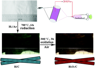
In the typical synthesis, polyacrylonitrile (PAN, average Mw = 150![[thin space (1/6-em)]](https://www.rsc.org/images/entities/char_2009.gif) 000, Aldrich) was used as the carbon source, N,N-dimethylformamide (DMF, anhydrous, 99.8%, Aldrich) as the solvent, and BiCl3/Bi(NO3)3 (99%, Alfa Aesar) as the source of Bi2O3. To prepare the precursor solution, 1 g PAN and 0.75 g BiCl3/Bi(NO3)3 were dissolved in 8 mL of DMF for 6 h under magnetic stirring. The mixture was transferred into a 5 mL plastic syringe equipped with a 21-gauge blunt tip needle and electrospun on a spinning system at 21 kV. Aluminium foil as the collector was located 15 cm away from the needle to collect the film. The as-collected nanofibers and comparison composite were all first heat-treated in a tube furnace at 5 °C min−1 up to 280 °C in air for 2 h to stabilize the fiber structure by reaction of PAN. Subsequently, the Bi/C nanofibers were obtained by carbothermal reaction at 700 °C for 6 h in Ar (90 vol%)/H2 (10 vol%). Finally, the films were treated at 300 °C for 3 h in air to get Bi2O3/C (BiCl3 for embedded Bi2O3/C and Bi(NO3)3 for bare Bi2O3/C, respectively). In addition, Bi2O3 macroparticles were also synthesized using the same procedures except that the oxidation temperature was increased from 300 to 500 °C for 3 h in order to eliminate the carbon.
000, Aldrich) was used as the carbon source, N,N-dimethylformamide (DMF, anhydrous, 99.8%, Aldrich) as the solvent, and BiCl3/Bi(NO3)3 (99%, Alfa Aesar) as the source of Bi2O3. To prepare the precursor solution, 1 g PAN and 0.75 g BiCl3/Bi(NO3)3 were dissolved in 8 mL of DMF for 6 h under magnetic stirring. The mixture was transferred into a 5 mL plastic syringe equipped with a 21-gauge blunt tip needle and electrospun on a spinning system at 21 kV. Aluminium foil as the collector was located 15 cm away from the needle to collect the film. The as-collected nanofibers and comparison composite were all first heat-treated in a tube furnace at 5 °C min−1 up to 280 °C in air for 2 h to stabilize the fiber structure by reaction of PAN. Subsequently, the Bi/C nanofibers were obtained by carbothermal reaction at 700 °C for 6 h in Ar (90 vol%)/H2 (10 vol%). Finally, the films were treated at 300 °C for 3 h in air to get Bi2O3/C (BiCl3 for embedded Bi2O3/C and Bi(NO3)3 for bare Bi2O3/C, respectively). In addition, Bi2O3 macroparticles were also synthesized using the same procedures except that the oxidation temperature was increased from 300 to 500 °C for 3 h in order to eliminate the carbon.
Material characterization
Morphological characterization of the Bi2O3/C nanofibers before and after sodium insertion were performed by scanning electron microscopy (SEM, NOVA 450, FEI) and by transmission electron microscopy (TEM, G2 FEI). The crystalline structures of the as-prepared nanofibers were characterized by X-ray diffraction (XRD, Shimadzu XRD-6000). The Raman spectra of the products were collected on a Thermo scientific FT-Raman spectrometer (FRA 106/s) using an Nd-line laser source with an excitation wavelength of 532 nm. The composition analysis of Bi2O3/C was performed with TG measurements (Diamond TGA/DSC 6300) with a heating rate of 10 °C min−1 in air and N2. The analysis of the valence states of the Bi2O3/C was performed with an X-ray electron spectrometer (XPS, AXIS-ULTRA DLD-600W).Fabrication of hierarchical CuBi2O4 microsphere electrodes
The hierarchical CuBi2O4 microsphere anodes were prepared by mixing 70 wt% CuBi2O4 microspheres, 20 wt% super P, and 10 wt% vinylidene fluoride (PVDF) to form a slurry, which was then coated onto copper foil and dried at 90 °C overnight under vacuum. The area of the electrode is about 1.53 cm2 while the loading of the whole material is about 2.5 mg cm−2.Fabrication of Li-ion batteries
Li-ion batteries were fabricated using lithium as the anode and 1 mol L−1 LiPF6 in a mixture of ethylene carbonate/diethyl carbonate (EC/DEC, 1![[thin space (1/6-em)]](https://www.rsc.org/images/entities/char_2009.gif) :
:![[thin space (1/6-em)]](https://www.rsc.org/images/entities/char_2009.gif) 1 by volume) as the electrolyte. All the cells were assembled in a glove box with a water/oxygen content lower than 0.1 ppm and tested at room temperature.
1 by volume) as the electrolyte. All the cells were assembled in a glove box with a water/oxygen content lower than 0.1 ppm and tested at room temperature.
Electrochemical measurements
The Bi2O3/C films were cut into circular samples (d = 12 mm) to be directly used as working electrodes without adding any polymeric binder and conductive additives. The average weight of the active material was about 0.53 mg cm−2 and the thickness of the working electrodes is about 0.30 mm. The cells were assembled with sodium as the counter electrode, 1 M NaPF6 in a mixture of ethylene carbonate/dimethyl carbonate (EC/DMC, 1![[thin space (1/6-em)]](https://www.rsc.org/images/entities/char_2009.gif) :
:![[thin space (1/6-em)]](https://www.rsc.org/images/entities/char_2009.gif) 1 by volume) with 5% fluoroethylene carbonate (FEC) as the electrolyte, and Celgard®3501 (Celgard, LLC Corp., USA) as the separator. All the cells were assembled in a glove box with a water/oxygen content lower than 0.1 ppm and tested at room temperature. The galvanostatic charge–discharge test was conducted on a LAND cycler (CT 2001, Wuhan Kingnuo Electronic Co., China). Cyclic voltammetric and electrochemical impedance spectroscopy measurements were carried out with coin cells using a CHI 760D electrochemical workstation (ChenHua Instruments Co., China).
1 by volume) with 5% fluoroethylene carbonate (FEC) as the electrolyte, and Celgard®3501 (Celgard, LLC Corp., USA) as the separator. All the cells were assembled in a glove box with a water/oxygen content lower than 0.1 ppm and tested at room temperature. The galvanostatic charge–discharge test was conducted on a LAND cycler (CT 2001, Wuhan Kingnuo Electronic Co., China). Cyclic voltammetric and electrochemical impedance spectroscopy measurements were carried out with coin cells using a CHI 760D electrochemical workstation (ChenHua Instruments Co., China).
Results and discussion
The preparation details are shown in Scheme 1. In this process, the bismuth ions facilitate the formation of carbon and the carbon frame confines the growth of Bi2O3 grains. Thus Bi2O3 nanoparticles uniformly embedded in the carbon matrix are successfully synthesized. Correspondingly, the morphology of the composites and the content of Bi2O3 particles can be controlled by changing the precursor solution composition and reaction conditions.
Fig. 1a shows the X-ray diffraction (XRD) patterns of the as-prepared samples. All diffraction peaks of the Bi/C sample correspond to an R![[3 with combining macron]](https://www.rsc.org/images/entities/char_0033_0304.gif) m space group of a rhombohedral crystal system Bi (JCPDS File No. 85-1331). After calcination in air, the entire diffraction peaks can be well indexed to the tetragonal Bi2O3 (JCPDS File No. 74-1374). No peaks of impurities are observed, demonstrating that Bi2O3/C with high purity has been successfully synthesized using the facile electrospinning method. The Raman spectra are applied to certify the existence of carbon and Bi2O3. As shown in Fig. 1b, two characteristic peaks located at 1344 and 1589 cm−1 can be attributed to the typical disorder-induced feature (D bands) and the E2g patterns of graphite carbon (G bands), respectively.35,36 Moreover, the peaks around 199, 302, and 432 cm−1 in a low band are Bi2O3 characteristic signals.37 Meanwhile, XRD patterns and Raman spectra of the pure carbon nanofibers (CNFs) are displayed (Fig. S1, ESI†). The X-ray photoelectron spectroscopy (XPS) spectra further clarify the structural change from simple substance bismuth to bismuth trioxide (Fig. 1c). The binding energy of 4f7/2 from 157 eV shifts to 159 eV and 4f5/2 from 162 eV shifts to 164 eV of bismuth elements, respectively, due to the elimination of twelve electrons (4Bi + 3O2 − 12e− → 2Bi2O3). The process of oxidation leads to the formation of a more stable electron configuration (4f145d106s2), which requires a higher electronic excitation energy. The XPS spectra of carbon and oxygen are shown in Fig. S2 (ESI†). All results effectively indicate that the carbonization and oxidation processes are complete and the final product is verified.
m space group of a rhombohedral crystal system Bi (JCPDS File No. 85-1331). After calcination in air, the entire diffraction peaks can be well indexed to the tetragonal Bi2O3 (JCPDS File No. 74-1374). No peaks of impurities are observed, demonstrating that Bi2O3/C with high purity has been successfully synthesized using the facile electrospinning method. The Raman spectra are applied to certify the existence of carbon and Bi2O3. As shown in Fig. 1b, two characteristic peaks located at 1344 and 1589 cm−1 can be attributed to the typical disorder-induced feature (D bands) and the E2g patterns of graphite carbon (G bands), respectively.35,36 Moreover, the peaks around 199, 302, and 432 cm−1 in a low band are Bi2O3 characteristic signals.37 Meanwhile, XRD patterns and Raman spectra of the pure carbon nanofibers (CNFs) are displayed (Fig. S1, ESI†). The X-ray photoelectron spectroscopy (XPS) spectra further clarify the structural change from simple substance bismuth to bismuth trioxide (Fig. 1c). The binding energy of 4f7/2 from 157 eV shifts to 159 eV and 4f5/2 from 162 eV shifts to 164 eV of bismuth elements, respectively, due to the elimination of twelve electrons (4Bi + 3O2 − 12e− → 2Bi2O3). The process of oxidation leads to the formation of a more stable electron configuration (4f145d106s2), which requires a higher electronic excitation energy. The XPS spectra of carbon and oxygen are shown in Fig. S2 (ESI†). All results effectively indicate that the carbonization and oxidation processes are complete and the final product is verified.
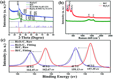 | ||
| Fig. 1 (a) XRD patterns of the as-prepared samples. (b) Raman spectra of the as-prepared samples. (c) XPS spectra of bismuth (4f). | ||
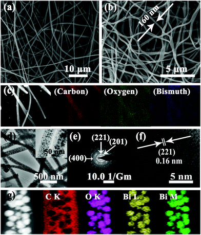
Fig. 2a and b reveal the morphologies of electrospun Bi/C and Bi2O3/C as investigated by field-emission scanning electron microscopy (FESEM). The fibers of the two samples are smooth and continuous with lengths of up to hundreds of micrometers. The average diameters of Bi/C and Bi2O3/C are ≈120 and 160 nm, respectively, and the fibers well interlink into a conductive 3-D network. The interlinked structure of Bi2O3/C nanofibers could effectively form binder free and flexible films, which can facilitate the contact between active materials and the electrolyte, leading to rapid charge and discharge processes. Simultaneously, the Bi2O3 nanoparticles stick on the carbon nanofibers, denoted as Bi2O3/C (bare) (Fig. S3, ESI†). The Bi2O3 nanoparticles are clearly visible and unordered sticking on the CNFs. Fig. 2d shows different resolution transmission electron microscopy (TEM) images of the Bi2O3/C sample. As expected, the Bi2O3 nanoparticles are uniformly embedded in CNFs without aggregation and the diagrams of particle size distribution in Fig. S4 (ESI†) manifest that the Bi2O3 grains in Bi2O3/C are around 10 nm. It is noteworthy that these ultra-small Bi2O3 nanoparticles provide much more surface area than bulk Bi2O3 and increase the electrochemical activity for SIBs.
The selected area electron diffraction (SAED) pattern (Fig. 2e) is well indexed to the pure Bi2O3 phase, corresponding to the diffraction peaks of the (201), (221) and (400) planes shown in the XRD pattern. Meanwhile, the HRTEM image (Fig. 2f) shows a group of parallel fringes with a d-spacing of 0.16 nm clearly, corresponding to the crystal (221) plane of rhombohedral Bi2O3. These results are consistent with the XRD patterns (Fig. 1a). Fig. 2c and g show the SEM and TEM elemental mapping images of Bi2O3/C, revealing that the Bi2O3 nanoparticles are homogeneously located in the carbon matrix. The Bi2O3 grain content in the CNFs is calculated from the TGA–DSC curves (Fig. S5, ESI†), based on the weight loss of carbon combustion and the mass ratio is ≈48 wt%. It is noteworthy that the content of Bi2O3 nanoparticles is determined by the BiCl3 concentration in the precursor solution (BiCl3, PAN and DMF). A series of content gradients of Bi2O3 in the composites are shown in Fig. S6 (ESI†). The lower the concentration of BiCl3, the lower the particle content in the carbon nanofiber. The Bi2O3 nanoparticles could be seen clearly with uniform distribution at the low concentration (Fig. S6a, ESI†) and their content is only 20 wt% in the carbon nanofibers (Table S1, ESI†). However, when the Bi2O3 nanoparticle content is more than 48 wt%, these nanoparticles aggregate together and even overflow from the carbon fibers. The surrounding carbon matrix exerts a continuous structure which plays a key role as a strong buffer region to accommodate the mechanical stress during ion insertion/deinsertion, especially for ions with a larger ionic radius such as sodium.
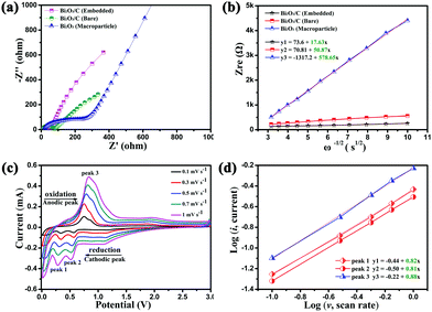
The binder free and flexible films (Bi2O3/C) were directly used as anodes for SIBs and the conductivity of the Bi2O3/C is revealed by the electrochemical impedance spectrum (EIS) and cyclic voltammograms (CVs). To demonstrate the hypothesis that better electrochemical performance could be achieved by the Bi2O3 nanoparticles embedded in CNFs, Bi2O3/C (Bare) and Bi2O3 (Macroparticle) (Fig. S7, ESI†) were used as references. The electrode made from Bi2O3/C shows higher electronic conductivity and lower charge-transfer resistance compared with those of Bi2O3/C (Bare) and Bi2O3 (Macroparticle) as revealed by the Nyquist plots (Fig. 3a). The simplified-contact-Randles equivalent circuit for the simulation of the Nyquist plots and more simulation information are shown in Depiction S1 (ESI†). It is noteworthy that the Na-ion diffusion coefficient (D) directly influences the cycling performance of the electrode material. The calculated formulas of the D value are presented in Depiction S2 (ESI†) and are directly determined by the Warburg factor (σ).38 The D value has negative correlation with the σ value and the values of σ are clearly shown in Fig. 3b. The σ values at open circuit are calculated to be 17.63, 50.87 and 578.65 for the Bi2O3/C, Bi2O3/C (Bare) and Bi2O3 (Macroparticle) electrodes, respectively, which are in accordance with the slopes of the real part of the complex impedance versus the square root of frequency, ω−1/2. For further emphasis, the CVs of the as-prepared Bi2O3/C sample at different scan rates from 0.1 to 1 mV s−1 are shown in Fig. 3c. When the scan rate is 0.1 mV s−1, two obvious reduction peaks at 0.33 and 0.57 V and an oxidation peak at 0.74 V are clearly observed, which recur intensively in the subsequent scans. With increase of the scan rate, the peak current increases without being proportional to the square root of the scan rate, which illustrates that the charge and discharge processes are composed of non-Faradaic and Faradaic behaviour.39,40 The relationship between the peak current (i) and scan rate (v) could be illustrated by the equations as follows:
 | (1) |
 | (2) |
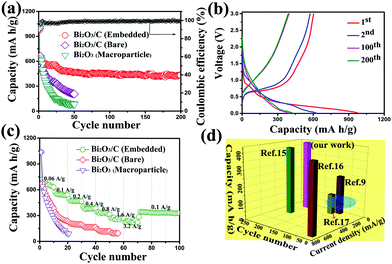
Due to the enhanced electronic conductivity and Na-ion diffusion coefficient, the cycling and galvanostatic curves of the Bi2O3/C electrode are further demonstrated (Fig. 4a and b). The reversible capacity of the Bi2O3/C composite is perfectly maintained compared with the other two samples and the electrode was galvanostatic charged and discharged at 100 mA g−1 for 200 cycles. After a few stabilization cycles, the reversible capacity can reach to 430 mA h g−1, and a high capacity retention of 63% can still be achieved over 200 cycles. For comparison, the Bi2O3/C (Bare) electrode exhibits a reversible capacity of 205 mA h g−1 after 50 cycles, while Bi2O3 (Macroparticle) displays a fast capacity fading (30 mA h g−1 after 20 cycles). The higher capacity retention of Bi2O3/C indicates that the uniform dispersion of Bi2O3 nanoparticles in the carbon matrix can generate a balanced stress upon prolonged cycling and maintain the integrity of the electrode. As shown in Fig. 4b, the voltage profiles showed sloping lines during both charge and discharge, which were consistent with the broad current peaks observed during CV scans (Fig. 3c). The sodiation capacity for the first cycle was 979 mA h g−1 with a Coulombic efficiency of around 51.1%. The large initial irreversible capacity is mainly due to the formation of an SEI film and electrochemical decomposition of the solvent on the electrode. It is noteworthy that some pyrolysis carbon (52%) is present in the CNFs, which would decrease the initial Coulombic efficiency and capacity of the Bi2O3/C electrode.41 Since CNFs can only provide a sodiation capacity of 70 mA h g−1 at the same current density after 200 cycles (Fig. S8b, ESI†), the capacity contributed by the Bi2O3 nanoparticles was around 430 mA h g−1 after 200 cycles, which provided a high capacity retention (69%). The Coulombic efficiency of the second cycle exceeded 98% and remained stable for the rest of the cycles. In addition, the typical charge and discharge voltage profiles of Bi2O3/C (Bare) and Bi2O3 (Macroparticle) are shown in Fig. S9 (ESI†).
To get further evidence of the improved electrochemical performance of Bi2O3/C for SIBs, the rate capabilities of both Bi2O3/C (Bare) and Bi2O3 (Macroparticle) electrodes were investigated (Fig. 4c). The Bi2O3/C electrode delivers a reversible capacity as high as 657, 546, 466, 379, 334, and 265 mA h g−1 when cycled at 60, 100, 200, 400, 800 and 1600 mA g−1, respectively. Even at a high current density of 3200 mA g−1, it still remains nearly at 230 mA h g−1. When the current density was set back to 100 mA g−1, the reversible capacity can be recovered up to 352 mA h g−1, showing excellent rate reversibility. The good rate performance can be attributed to the following facts: firstly, the 1-D carbon nanofibers cross-linked together to form a 3-D network, which could effectively facilitate the ionic/electron diffusion kinetics. Furthermore, the ultra-small Bi2O3 nanoparticles are readily accessible to the electrolyte and can easily be fully utilized for sodium-storage. It is noteworthy that the binder-free electrodes can improve the electronic conductivity and energy density. Lastly, the electrochemical reactions of the Bi2O3/C electrode are mainly controlled by the pseudo-capacitive behaviour, leading to a fast Na-ion insertion/extraction, and efficiently rendering the high rate capability. By contrast, the rate capabilities of Bi2O3/C (Bare) and Bi2O3/C (Macroparticle) are presented and both of them show very poor capacity even at the current density of 100 mA g−1 (170 and 80 mA h g−1, respectively). As can be concluded, the smallest particle size and high conductivity of the electrode material can significantly facilitate the electron transfer and Na-ion diffusion kinetics, which endow Bi2O3/C with excellent rate capability.
Fig. 4d illustrates the superiority of bismuth metal oxidation to prepare Bi2O3 nanoparticles over other Bi2O3 electrodes reported in the recent literature. Bismuth nanoparticles wrapped by graphene have been synthesized and deliver a capacity of 240 mA h g−1 at 50 mA h g−1 after 80 cycles (ref. 9); bismuth nanoparticles embedded in carbon spheres were prepared using an aerosol spray pyrolysis technique and deliver a capacity of 100 mA h g−1 at 123.5 mA g−1 after 100 cycles (ref. 17). Both of them showed poor cycling performance and provided low capacity due to the inherent specific capacity (384 mA h g−1). Furthermore, the capacities of the Bi2O3 anodes are 410 and 413 mA h g−1 for ref. 15 and 16, respectively, which are far above the highest capacity (240 mA h g−1) of the bismuth metal. It is noteworthy that the Bi2O3/C electrode delivers a high reversible capacity of 430 mA h g−1, which is more superior over other Bi2O3 electrodes. These results can emphasize that the significance of Bi2O3 by bismuth metal oxidation and Bi2O3 ultra-small nanoparticles embedded in carbon nanofibers can effectively improve the cycling performance for SIBs.
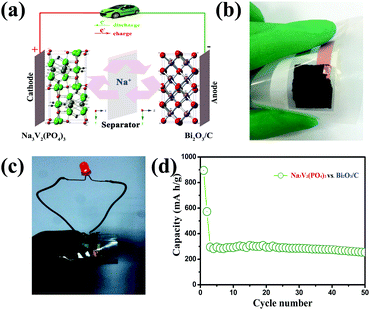
We have measured the electrochemical performance of full cells which are assembled with a coupling NASICON-type Na3V2(PO4)3 cathode and Bi2O3/C anode. The NASICON-type Na3V2(PO4)3 has been considered as a promising cathode material (theoretical capacity of 117.6 mA h g−1) for SIBs owing to its fast Na-ion diffusion, wide voltage plateau, and high thermal stability. So, it is used as a cathode material to couple with the Bi2O3/C anode.42,43Fig. 5a illustrates the composition of the Bi2O3/C–Na3V2(PO4)3 full cell. The Bi2O3/C anode has been demonstrated to achieve a six-electron reaction, and the Na3V2(PO4)3 cathode possesses a theoretical 2Na extraction capability. The reaction of the full cell is shown in eqn (3):
 | (3) |
Conclusions
In summary, a flexible binder-free film composed of bismuth oxide nanoparticles embedded in carbon nanofibers (Bi2O3/C) was prepared by a feasible electrospinning method and used as a sodium ion battery (SIB) anode. The CNFs form a conductive 3-D network and thus a flexible binder-free film is constructed. When used as an anode material for SIBs, the Bi2O3/C electrode exhibits an excellent cycling stability (430 mA h g−1 after 200 cycles), rate capability (230 mA h g−1 at a current density of 3.2 A g−1) and sustained capacity in a full cell (252 mA h g−1 after 50 cycles at 400 mA g−1) due to its ultra-small Bi2O3 nanoparticles embedded in CNFs, no auxiliary additives, enhanced conductivity and high Na-ion diffusion coefficient. The superior electrochemical performance further demonstrates that Bi2O3 nanoparticles have great potential for practical applications, especially in flexible energy storage devices.Acknowledgements
This work was supported by the National Basic Research Program of China (Grant No. 2015CB755602 and 2013CB922104), NSFC (51673077 and 21474034). We also thank the Analytical and Testing Center of Huazhong University of Science and Technology and the Center of Micro-Fabrication and Characterization (CMFC) of WNLO for the use of their facilities.Notes and references
- X. Y. Lai, J. E. Halpert and D. Wang, Energy Environ. Sci., 2012, 5, 5604–5618 CAS.
- J. Wang, H. Tang, H. Ren, R. Yu, J. Qi, D. Mao, H. Zhao and D. Wang, Adv. Sci., 2014, 1, 1400011 CrossRef PubMed.
- J. Wang, N. Yang, H. Tang, Z. Dong, Q. Jin, M. Yang, D. Kisailus, H. Zhao, Z. Tang and D. Wang, Angew. Chem., Int. Ed., 2013, 52, 6417–6420 CrossRef CAS PubMed.
- H. Ren, J. Sun, R. Yu, M. Yang, L. Gu, P. Liu, H. Zhao, D. Kisailus and D. Wang, Chem. Sci., 2016, 7, 793–798 RSC.
- J. Qi, X. Lai, J. Wang, H. Tang, H. Ren, Y. Yang, Q. Jin, L. Zhang, R. Yu, G. Ma, Z. Su, H. Zhao and D. Wang, Chem. Soc. Rev., 2015, 44, 6749–6773 RSC.
- H. Tang, C. M. Hessel, J. Wang, N. Yang, R. Yu, H. Zhao and D. Wang, Chem. Soc. Rev., 2014, 43, 4281–4299 RSC.
- N. Mahmood, T. Y. Tang and Y. L. Hou, Adv. Energy Mater., 2016, 6, 1600374 CrossRef.
- Y. Xu, Y. Zhu, Y. Liu and C. Wang, Adv. Energy Mater., 2013, 3, 128–133 CrossRef CAS.
- D. Su, S. Dou and G. Wang, Nano Energy, 2015, 12, 88–95 CrossRef CAS.
- Y. Zhu, X. Han, Y. Xu, Y. Liu, S. Zheng, K. Xu, L. Hu and C. Wang, ACS Nano, 2013, 7, 6378–6386 CrossRef CAS PubMed.
- Y. Li, M. A. Trujillo, E. Fu, B. Patterson, L. Fei, Y. Xu, S. Deng, S. Smirnov and H. Luo, J. Mater. Chem. A, 2013, 1, 12123 CAS.
- X. Cui, X. Yu, L. Hou, A. Gagnoud, Y. Fautrelle, R. Moreau, Z. Ren, X. Lu and X. Li, J. Alloys Compd., 2016, 684, 21–28 CrossRef CAS.
- H. Che, J. Chen, K. Huang, W. Hu, H. Hu, X. Liu, G. Che, C. Liu and W. Shi, J. Alloys Compd., 2016, 688, 882–890 CrossRef CAS.
- Q. Wang, X. Shi, E. Liu, J. C. Crittenden, X. Ma, Y. Zhang and Y. Cong, J. Hazard. Mater., 2016, 317, 8–16 CrossRef CAS PubMed.
- C. Nithya, ChemPlusChem, 2015, 80, 1000–1006 CrossRef CAS.
- M. K. Kim, S. H. Yu, A. Jin, J. Kim, I. H. Ko, K. S. Lee, J. Mun and Y. E. Sung, Chem. Commun., 2016, 52, 11775–11778 RSC.
- F. Yang, F. Yu, Z. Zhang, K. Zhang, Y. Lai and J. Li, Chem. – Eur. J., 2016, 22, 2333–2338 CrossRef CAS PubMed.
- T. N. Ramesh and P. V. Kamath, Electrochim. Acta, 2008, 53, 4721–4726 CrossRef CAS.
- Y. Li, H. Zhang, Y. Wang, P. Liu, H. Yang, X. Yao, D. Wang, Z. Tang and H. Zhao, Energy Environ. Sci., 2014, 7, 3720–3726 CAS.
- M. Chen, J. Wang, H. Tang, Y. Yang, B. Wang, H. Zhao and D. Wang, Inorg. Chem. Front., 2016, 3, 1065–1070 RSC.
- F. Wang, J. Wang, H. Ren, H. Tang, R. Yu and D. Wang, Inorg. Chem. Front., 2016, 3, 365–369 RSC.
- W. Fang, N. Zhang, L. Fan and K. Sun, J. Power Sources, 2016, 333, 30–36 CrossRef CAS.
- J. Y. Wang, H. J. Tang, H. Wang, R. B. Yu and D. Wang, Mater. Chem. Front., 2017, 1, 414–430 RSC.
- J. Zhang, H. Ren, J. Wang, J. Qi, R. Yu, D. Wang and Y. Liu, J. Mater. Chem. A, 2016, 4, 17673–17677 CAS.
- H. Li, H. Ma, M. Yang, B. Wang, H. Shao, L. Wang, R. Yu and D. Wang, Mater. Res. Bull., 2017, 87, 224–229 CrossRef CAS.
- X. X. Yu, H. Yin, H. X. Li, W. Zhang, H. Zhao, C. Li and M. Q. Zhu, Nano Energy, 2017, 34, 155–163 CrossRef CAS.
- H. Ren, R. Yu, J. Wang, Q. Jin, M. Yang, D. Mao, D. Kisailus, H. Zhao and D. Wang, Nano Lett., 2014, 14, 6679–6684 CrossRef CAS PubMed.
- H. Yin, Q. Li, M. Cao, W. Zhang, H. Zhao, C. Li, K. Huo and M. Zhu, Nano Res., 2017 DOI:10.1007/s12274-016-1408-z.
- L. Wang, B. Gao, C. Peng, X. Pensg, J. Fu, P. K. Chu and K. Huo, Nanoscale, 2015, 7, 13840–13847 RSC.
- J. Wang, H. Tang, L. Zhang, H. Ren, R. Yu, Q. Jin, J. Qi, D. Mao, M. Yang, Y. Wang, P. Liu, Y. Zhang, Y. Wen, L. Gu, G. Ma, Z. Su, Z. Tang, H. Zhao and D. Wang, Nat. Energy, 2016, 1, 16050 CrossRef CAS.
- L. Zeng, W. Zeng, Y. Jiang, X. Wei, W. Li, C. Yang, Y. Zhu and Y. Yu, Adv. Energy Mater., 2015, 5, 1401377 CrossRef.
- X. Pu, L. Li, H. Song, C. Du, Z. Zhao, C. Jiang, G. Cao, W. Hu and Z. L. Wang, Adv. Mater., 2015, 27, 2472–2478 CrossRef CAS PubMed.
- E. C. Self, E. C. McRen, R. Wycisk and P. N. Pintauro, Electrochim. Acta, 2016, 214, 139–146 CrossRef CAS.
- C. Kim, K. S. Yang, M. Kojima, K. Yoshida, Y. J. Kim, Y. A. Kim and M. Endo, Adv. Funct. Mater., 2006, 16, 2393–2397 CrossRef CAS.
- Y. Kang, Y. Yang, L. C. Yin, X. Kang, G. Liu and H. M. Cheng, Adv. Mater., 2015, 27, 4572–4577 CrossRef CAS PubMed.
- M. J. Xie, J. Yang, J. Y. Liang, X. F. Guo and W. P. Ding, Carbon, 2014, 77, 215–225 CrossRef CAS.
- M. M. Martins, D. S. Silva, L. R. P. Kassab, S. J. L. Ribeiro and C. B. d. Araújo, J. Braz. Chem. Soc., 2015, 26, 2520–2524 CAS.
- Y. Zhao, L. Peng, B. Liu and G. Yu, Nano Lett., 2014, 14, 2849–2853 CrossRef CAS PubMed.
- H. Yin, M. L. Cao, X. X. Yu, C. Li, Y. Shen and M. Q. Zhu, RSC Adv., 2017, 7, 13250–13256 RSC.
- X. Xiang, K. Zhang and J. Chen, Adv. Mater., 2015, 27, 5343–5364 CrossRef CAS PubMed.
- H. Yin, X. X. Yu, Q. W. Li, M. L. Cao, W. Zhang, H. Zhao and M. Q. Zhu, J. Alloys Compd., 2017, 706, 97–102 CrossRef CAS.
- F. Shen, W. Luo, J. Dai, Y. Yao, M. Zhu, E. Hitz, Y. Tang, Y. Chen, V. L. Sprenkle, X. Li and L. Hu, Adv. Energy Mater., 2016, 6, 1600377 CrossRef.
- Y. Xu, M. Zhou and Y. Lei, Adv. Energy Mater., 2016, 6, 1502514 CrossRef.
Footnote |
| † Electronic supplementary information (ESI) available. See DOI: 10.1039/c7qm00128b |
| This journal is © the Partner Organisations 2017 |

