A carbon foam-supported high sulfur loading composite as a self-supported cathode for flexible lithium–sulfur batteries†
Miao
Zhang
ab,
Kamran
Amin
b,
Meng
Cheng
b,
Hongxin
Yuan
b,
Lijuan
Mao
*b,
Wei
Yan
*a and
Zhixiang
Wei
 *b
*b
aSchool of Energy and Power Engineering, Xi'an Jiaotong University, Xi'an, 710049, P.R. China. E-mail: yanwei@xjtu.edu.cn
bCAS Key Laboratory of Nanosystem and Hierarchical Fabrication, CAS Center for Excellence in Nanoscience, National Center for Nanoscience and Technology, Beijing, 100190, P. R. China. E-mail: maolj@nanoctr.cn; weizx@nanoctr.cn
First published on 30th October 2018
Abstract
A binder-free, self-supported, flexible cathode is explored for application in flexible lithium–sulfur (Li–S) batteries. The cathode is constructed using nitrogen (N)-doped carbon foam/carbon nanotubes (CNTs) as the scaffold and filled with poly(3,4-ethylenedioxythiophene) (PEDOT)-encapsulated sulfur nanoparticles as the active material. The dense CNTs coated on the skeleton of the 3D N-doped foam enhance flexibility, and the highly conductive CNTs are crossed and twined together to create an interconnected skeleton for rapid electron transport. The conductive PEDOT shell of sulfur nanoparticles and the N-doping of the carbon foams restrain the dissolution of polysulfides through the enhanced chemisorption of lithium polysulfides. The best cathode with a sulfur loading of 2.6 mg cm−2 has an eminent capacity of 1395 mA h g−1 during the initial cycle at 0.1 C. Furthermore, freestanding cathodes are assembled into flexible Li–S batteries, which demonstrate significant achievement at various bending angles. The capacity fading rate is 0.16% per cycle at 30° after 120 cycles. Its high sulfur loading, high capacitance, and good flexibility make this cathode material a promising candidate for potential application in flexible electronics.
Introduction
The increasing interest in wearable devices in the past decade is driving the progress of flexible charge storage devices. To integrate them into flexible electronic systems, these charge storage devices are designed and developed into wearable power supply systems.1–5 Flexible energy storage devices are a crucial part of flexible electronic systems because they supply the necessary energy for their operation.6–8 To promote the development of flexible devices, flexible batteries with good mechanical properties and high electrochemical performance are critical.9–14 Lithium–sulfur (Li–S) batteries have attracted considerable attention as potential next-generation batteries because of their high energy density and theoretical capacity.14,15 In addition, sulfur is environment-friendly and naturally abundant.16–18 Unlike other high energy density battery systems, such as the Li–air battery, the Li–S battery effectively prevents exposure to the atmosphere and avoids side reactions.19 Therefore, the Li–S battery has become the most promising technology for next generation batteries with a high energy density.20Although an unprecedented cell performance has been achieved by Li–S batteries in the last decade, we noticed that most of the studies on Li–S cells in the past decade involved an assembly with a low sulfur loading of less than 2 mg cm−2.21–24 To promote development for future applications, an electrode with high sulfur loading is essential. The minimum value for high sulfur loading is 2.0 mg cm−2, and even a higher loading is preferable to facilitate potential research on Li–S batteries.19,25–28 However, several challenges are associated with high-sulfur electrodes, including the shuttle effect, poor electrochemical activity of insulating sulfur, and volume expansion.29–34 Therefore, finding a balance between performance and sulfur mass in future studies on Li–S batteries is important.35 As highly conductive and film-forming materials, carbon nanotubes (CNTs) have been used as hosts for high sulfur loading;36,37 in addition, the CNT network also provides highly conductive electron pathways for a high sulfur utilization.38 Porous carbon materials and their composites with a large surface area have also been investigated to improve the sulfur content and confine polysulfides into nanopores.25,31,32,39,40 For instance, Manthiram et al. selected highly conductive Fe3O4 as a polar oxide and reasonably designed a hollow carbon@Fe3O4 nanobox architecture, which can be used as a high sulfur loading host for Li–S cells.40 The same group also designed a carbon–cotton cathode with a superior loading ability of the active material, which was composed of a cross-linked spiral carbon fiber network armored with microporous reaction sites.41 Recently, porous macrocellular carbon also became a member of the macroporous material family as the host of sulfur.42 Moreover, in graphene/CNTs,22,43–47 the compact nanoconfined structure,48 porous macrocellular carbon, surface functionalization or heteroatom doping has been studied to further suppress the dissolution of polysulfides.21,32,49,50
The cathodes of high-loading and high-energy Li–S cells are conventionally assembled through the slurry coating method. A mixture of sulfur with a suitable conductive agent and binder is used to make the slurry, which is then coated on a metal current collector. This method allows the loading of more active materials on the electrode to enhance the sulfur content above 2 mg cm−2; however, the performance of electrodes is seriously restricted by low charge/ionic transport and the delamination of coating from the current collector.14 In addition, a high loading of sulfur in the cathode makes the cathode too fragile to be bent. Furthermore, a large polarization would generate low energy efficiency because of lithium diffusion in the thick electrode. To improve the performance of Li–S batteries, an interconnected highly conductive material needs to be used as the current collector, which could avoid the mass of active material peeling off from the current collector, and the 3D interconnected hybrid structure would enhance the transport of electrons and ions effectively.28 Therefore, designing a freestanding electrode with excellent conductivity that can be used directly as a cathode without any additive is crucial. To date, achieving a balance between flexibility and high areal sulfur loading has remained a challenging task.
Here, we designed a novel 3D hybrid structure. A N-doped carbon foam (NCF) was obtained via the pyrolysis of N-rich melamine foam with polyaniline (PANI) nanowires. CNTs were then coated to increase the flexibility of the scaffold (abbreviated as NCF/CNT). PEDOT-encapsulated sulfur nanoparticles (PEDOT@S) were synthesized using a solution method. A facile liquid phase immersion/adsorption approach was used to infuse PEDOT@S into the 3D NCF/CNT scaffold. Finally, the NCF/CNT/PEDOT@S electrode was obtained. This well-designed structure exhibits several advantages. (1) PEDOT@S was synthesized to improve sulfur utilization, thereby effectively trapping and restricting polysulfides inside the shell. The highly conducting PEDOT facilitates the electron transport in the electrode. (2) N-Doping in the hybrid cathode was caused by pyrolysis of commercial melamine foam (MF) with PANI nanowires, thereby producing rich surface anchoring sites that can easily trap polysulfides via chemisorption. (3) CNTs intertwined around the 3D conductive network, which not only improved the electrode conductivity by providing a fully connected conductive framework but also served as a mechanically strong and flexible backbone. (4) The aligned PANI nanowire arrays divided the 3D macroporous framework into small void spaces, which guaranteed high sulfur loading, whereas the nanowire arrays enabled the easy coating of CNTs onto the entire surface of the foam frame. Consequently, the NCF/CNT/PEDOT@S hybrid cathode offers a high capacity of 1395 mA h g−1 and 1096 mA h g−1 based on sulfur loadings of 2.6 and 3.5 mg cm−2, respectively. Notably, a flexible battery prototype is successfully assembled. This prototype maintains an outstanding electrochemical performance in different bending states, thereby making it a promising candidate for potential applications in flexible electronics.
Results and discussion
Fig. 1 shows the schematic of the fabricated flexible NCF/CNT/PEDOT@S hybrid cathode. We selected a simple, commercial MF for its dual function as a 3D template and carbon source to build a self-supporting flexible electrode. PANI was coated onto the MF skeleton (MF-P) not only to improve the nitrogen content but also to divide large voids into smaller ones, followed by the immersion/adsorption approach to adsorb the CNT solution, which yielded MF-P/CNT. After drying and further carbonization at 800 °C, the MF-P/CNT was transformed into NCF/CNT. To achieve high electrochemical performance, the NCF/CNT was immersed in PEDOT@S suspension. The PEDOT@S dispersion could be easily infused into the NCF/CNT foam due to the unordered framework of the NCF/CNT, which formed considerable void spaces. Finally, the flexible self-supporting electrode was successfully assembled for a flexible battery.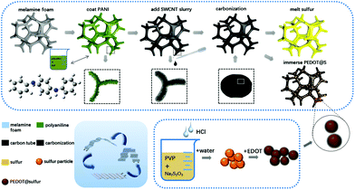 | ||
| Fig. 1 Schematic of the structure and fabrication process of the flexible binder-free NCF/CNT/PEDOT@S and NCF/CNT@S electrodes. | ||
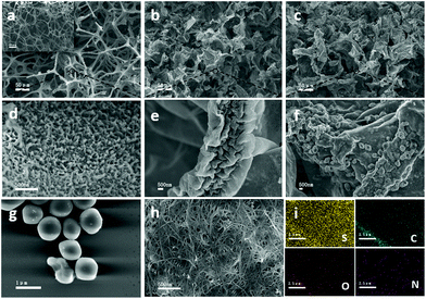
A scanning electron microscope (SEM) and FESEM were used to characterize the morphologies and structure of the materials. Fig. 2a, b and c show the images of the MF-P, NCF/CNT, and NCF/CNT/PEDOT@S. The inset shows the morphology of commercial MF. The vertically aligned PANI nanoarrays were obtained on the outer and inner skeletons of MF (Fig. 2d). Fig. 2e shows the high-magnification SEM image of the NCF/CNT obtained via pyrolysis. The PANI nanoarrays were hidden below the CNTs due to the CNT coating. The skeletons of the NCF/CNT film shrunk markedly after pyrolysis. The wrinkled CNT layer not only improved conductivity, but also provided many active sites. Moreover, the hybrid NCF/CNT film offered substantial space from the randomly and unordered interconnected conductive framework. The morphology of the NCF/CNT/PEDOT@S electrode at high magnification is shown in Fig. 2f, where the particles of PEDOT@S are clearly on the surface of the NCF/CNT hybrid film. Fig. 2g shows the diameter of PEDOT@S at approximately 1 μm. The low-magnification image is shown in Fig. S1a.† By contrast, the electrode fabricated through the melt diffusion of sulfur on the NCF/CNT hybrid film (NCF/CNT@S) is shown in Fig. 2h. The elemental mapping of S, C, O, and N over the entire hybrid skeletons was confirmed by FESEM in Fig. 2i and S1b in the ESI.† The sulfur content of the NCF/CNT/PEDOT@S and NCF/CNT@S electrodes is 3.5 mg cm−2.
The Raman spectra (Fig. S2a and S2b†) of NCF/CNT were obtained by pyrolysis at 800 °C (700 °C was also used for comparing the electrode performance at different pyrolytic temperatures). The three characteristic peaks at ∼1348, ∼1584, and ∼2663 cm−1 implied the existence of a disordered carbon (D band), in-plane vibration (G band), and CNTs, respectively; the defects of the carbon lattice were reflected by the IG/ID value.51 Therefore, the enhanced defects of the material caused by the heteroatom content may result in the lowest IG/ID value of NCF/CNT/PEDOT@S. The surface chemical composition of NCF/CNT/PEDOT@S was investigated via XPS. As shown in Fig. S2c and S2d,† the two characteristic peaks at 395.5 eV and 400.8 eV indicate the presence of pyridinic N and pyrrolic N, respectively, doped in the NCF/CNT films.15,52 Fig. S2e† shows the XRD patterns of NCF/CNT/PEDOT@S, NCF/CNT@S and NCF/CNT composites. The NCF/CNT/PEDOT@S and NCF/CNT@S composites exhibited peaks from 20° to 30° perfectly matched with sulfur.20 FTIR spectroscopy was used to further investigate the chemical bond structure, as shown in Fig. S2f,† the peaks are the same in NCF/CNT/PEDOT@S, NCF/CNT@S and NCF/CNT, indicating that sulfur has no impact on NCF/CNT/PEDOT@S and NCF/CNT@S electrodes. The N content of NCF/CNT was measured via elemental analysis and determined to be 7.095%.
The sulfur content of PEDOT@S is ca. 80% by calculation via the TGA curves of PEDOT@S, PEDOT and sulfur nanoparticles in which the contribution of PEDOT is only ca. 2% (Fig. S3†).
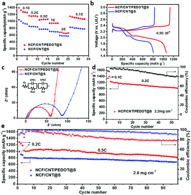
The electrochemical properties of the NCF/CNT/PEDOT@S cathode were evaluated systematically. The sulfur loading was kept constant at 2.6 mg cm−2. The CV values of the NCF/CNT/PEDOT@S and NCF/CNT@S cathodes were measured at a scan rate of 0.1 mV s−1 (Fig. S4 in ESI†). Both NCF/CNT/PEDOT@S and NCF/CNT@S show two pairs of reduction and oxidation peaks. During the cathodic scan, two main reaction peaks appear at approximately 2.3 and 2.0 V which are representative of S8 to higher-order lithium polysulfides and higher-order polysulfides to lower-order polysulfides.41 The rate performances of the NCF/CNT/PEDOT@S and NCF/CNT@S cathodes at current rates ranging from 0.1 C to 2.0 C were compared in Fig. 3a, and the NCF/CNT/PEDOT@S cathode exhibited a superior property over the NCF/CNT@S cathode. At current densities of 0.1, 0.2, 0.5, 1.0, and 2.0 C, the discharge capacities are 1395, 1167, 1036, 950, and 683 mA h g−1, respectively. For the NCF/CNT@S electrode, the corresponding discharge capacities are lower than those of NCF/CNT/PEDOT@S. In addition, to illustrate the influence of pyrolytic temperature on the electrode, the histogram of the rate performances of the NCF/CNT/PEDOT@S and NCF/CNT@S electrodes pyrolyzed at 700 °C and 800 °C is shown in Fig. S5.† The NCF/CNT/PEDOT@S cathode pyrolysis at 800 °C has the optimal rate performance. These results suggest that PEDOT@S plays an important role in enhancing the performance. The increased content of insulating sulfur always generates low conductivity. The PEDOT shell prevents dissolution by trapping polysulfides. Moreover, the PEDOT with high conductivity facilitates intimate contact between electrons and the insulating sulfur. The synergistic effects of PEDOT@S and N-doping on the NCF/CNT/PEDOT@S electrode are responsible for its high performance. Moreover, the NCF/CNT/PEDOT@S and NCF/CNT@S cathodes consisted of two well-defined charge and discharge plateaus in the typical discharge/charge curves measured at 0.5 C during the 20th cycle (Fig. 3b). The NCF/CNT/PEDOT@S and NCF/CNT@S electrodes were further analyzed via EIS. Both Nyquist plots display two similar semicircles (Fig. 3c). The semicircle with a high frequency corresponds to the charge transfer resistance (Rct).53 The equivalent circuit was drawn using the ZsimDemo software to simulate the experimental results. The calculated Rct value for the NCF/CNT/PEDOT@S (57.1 Ω) electrode is lower than that of the NCF/CNT@S (80.9 Ω) electrode. This finding can be attributed to the favorable charge and ion transfer processes in the carbon framework and the close contact with the active material.54 In Fig. 3d, the NCF/CNT/PEDOT@S electrode with a sulfur content of 2.2 mg cm−2 was subjected to a cycling stability test at 0.2 C. The initial discharge capacity was 1233 mA h g−1, and it remained at 1011 mA h g−1 (82% of its initial capacity) after 55 cycles. Furthermore, the NCF/CNT/PEDOT@S and NCF/CNT@S electrodes exhibited good cycling stability after 100 cycles at 0.5 C with a sulfur loading of 2.6 mg cm−2. The NCF/CNT/PEDOT@S electrode retained a discharge capacity of 802 mA h g−1 after 100 cycles with a decay rate of 0.2% per cycle. By contrast, the discharge capacity of NCF/CNT@S was 667 mA h g−1 after 100 cycles (Fig. 3e). The results show that the NCF/CNT/PEDOT@S electrode achieves higher capacity and outstanding cycling stability because of the good confinement capability, high conductivity, and adsorption of polysulfides, which prevent dissolution and enhance performance.
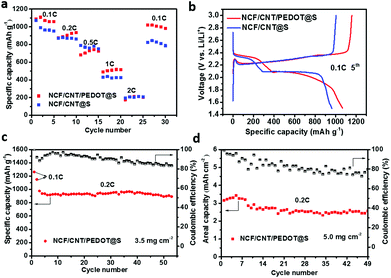
To investigate the effect of a higher mass loading of sulfur on the electrodes, a comparative analysis with 3.5 mg cm−2 and 5.0 mg cm−2 of sulfur was performed. Fig. 4a presents the corresponding rate capacities of the NCF/CNT/PEDOT@S and NCF/CNT@S electrodes at a sulfur loading of 3.5 mg cm−2. The discharge capacities of the two cathodes are 1091 mA h g−1 and 1063 mA h g−1 at 0.1 C, respectively, and the capacity of the NCF/CNT/PEDOT@S electrode can reach 1018 mA h g−1 when the current rate is switched back to 0.1 C, thereby indicating the outstanding reversibility of the NCF/CNT/PEDOT@S electrode. The polarization of the electrode was increased with a high sulfur content, which led to an evident decline in the discharge capacity at 1 C and 2 C. Fig. 4b shows the discharge/charge profiles at 0.1 C (3.5 mg cm−2) with the same plateau at 2.3 V and 2.1 V. Fig. 4c further illustrates the cycling performance of the NCF/CNT/PEDOT@S electrode with a sulfur loading of 3.5 mA h g−1, which shows a high capacity and indicates that the PEDOT shell plays a significant role in preventing dissolution through physical confinement, and the high conductive polymer can effectively maintain the structural stability of the electrode.55 To further investigate the performance of the electrode, a sulfur loading of 5.0 mg cm−2 was used, in which the NCF/CNT/PEDOT@S electrode still achieved a considerably better cycling stability (nearly 79%) and areal capacity (Fig. 4d).
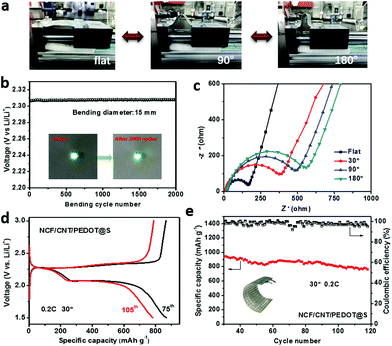
Finally, the self-supporting cathode was assembled to a flexible battery and demonstrated for wearable applications. Wearable electronic devices undergo frequent bending and extending throughout their entire life cycle. The basic condition for the practical applications of flexible batteries is their mechanical properties. Hence, their bending performance and bending stability were measured via a dynamic bending experiment. Fig. 5a shows the battery at different stages during the experiment. In the dynamic bending test, the flexible battery exhibited excellent cycling stability, maintaining a constant potential of approximately 2.3 V after 2000 cycles with a bending diameter of 1.5 cm (Fig. 5b). Therefore, this cathode exhibits considerable potential for applications in the development of a flexible battery. Fig. S6† shows the structure of the mechanical bending device. It contains one fixed actuator, whereas the other actuator can move back and forth. The battery was fixed between two actuators. The back-and-forth motion of the device actuator causes the battery to become flat and to bend repetitively. The bending distance of the battery was set to 1.5 cm. In addition, EIS investigations of the flexible battery in the flat state at 30°, 90° and 180° from 100 kHz to 10 MHz were conducted (Fig. 5c). In the Nyquist plots, the semicircle in the high-frequency range can be assigned to the charge transfer resistance, and a straight line in the low-frequency range represents lithium ion diffusion.2 The charge transfer resistance in the flat state is approximately 150.8 Ω, which is lower than those at 30° (385.8 Ω), 90° (469.7 Ω) and 180° (535.05 Ω), thereby indicating the excellent electrochemical kinetics of the flat cathode due to the close contact between the active material and the conductive substrate. Moreover, the good adhesion of the active materials and the substrate is important in flexible batteries. The charge/discharge curves of the flexible battery in the 75th and 105th cycles at 30° are shown in Fig. 5d, where a typical two-plateau behaviour is observed, which demonstrates its excellent cycling stability. The prominent cycling performance at a bending angle of 30° is shown in Fig. 5e, with a capacity fading rate of 0.16% per cycle at 0.2 C after 120 cycles.
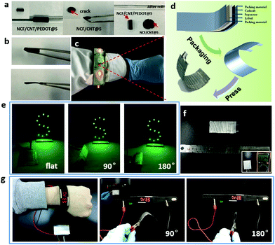
Electrode flexibility and allocation in flexible batteries were investigated systematically (Fig. 6). The NCF/CNT/PEDOT@S electrode retained its monolithic structure after being twined around a glass rod with a diameter of 5 mm, whereas the cathode fabricated through the melt diffusion of sulfur was broken when it was twined around a glass rod (Fig. 6a). This result indicates the excellent mechanical properties of the NCF/CNT/PEDOT@S cathode fabricated through our method using PEDOT@S. Fig. 6b shows the self-supporting electrode before and after pressing. The thick film can absorb more active materials and maintain good flexibility after pressing. The NCF/CNT/PEDOT@S electrode, as a self-supporting cathode, was fabricated for a soft-package battery to confirm the feasibility of a flexible design in practical applications. The flexible battery was then embedded into a flexible bracelet, which worked normally (Fig. 6c). The architecture of the flexible battery is shown in Fig. 6d. The freestanding NCF/CNT/PEDOT@S electrode and lithium foil served as the cathode and anode, respectively. All layers were in contact and were pressed with a mold to form a lightweight, thin, and flexible Li–S battery. The obtained soft-package Li–S battery was capable of lighting 11 light-emitting diodes (LEDs) in the bending (bending angle of 90°) and folding (bending angle of 180°) states (Fig. 6e). The size of the flexible battery in the bracelet is shown in Fig. 6f. The initial voltage output was 3.1 V. To further demonstrate the practical applications of the NCF/CNT/PEDOT@S cathode, a commercial smart watch was used to test the performance of the flexible NCF/CNT/PEDOT@S battery. As shown in Fig. 6g, the watch maintained good functionality when the battery was bent at different angles, which signifies that our design conforms to the commercial requirements for flexible electronics.
Conclusions
In summary, a multifunctional 3D freestanding hybrid NCF/CNT/PEDOT@S cathode for Li–S cells with high sulfur loading was fabricated. The NCF/CNT film with PEDOT-coated sulfur nanoparticles as the active material exhibits high conductivity, strong physical confinement for polysulfides, and excellent flexibility in the self-supporting electrode. The rich N content effectively promotes the chemisorption of lithium polysulfides. In addition, the CNT layer on the frame of pyrolytic MF-P provides high conductivity and excellent mechanical properties. Consequently, the NCF/CNT/PEDOT@S electrode delivers extremely high capacities (1395–1096 mA h g−1) even with a high sulfur loading (2.6–3.5 mg cm−2). Moreover, a stable cycling performance and high capacity can be maintained by the flexible soft-package Li–S battery when it is bent at various angles. These results indicate the excellent flexibility and stable electrochemical performance of the self-supporting NCF/CNT/PEDOT@S electrode, and accordingly, its considerable potential for practical applications in flexible electronics.Experimental section
Preparation of 3D flexible NCF/CNT hybrids
Commercial melamine foam (MF) was washed thrice with distilled water and alcohol. The preparation method for 3D flexible MF-P films was reported in our previous paper.56 CNT powder was purified at 900 °C in argon air mix water vapor for 2 h and added to 200 mL water, and then ultrasonically dispersed for 2 h to form a uniformly dispersed CNT suspension (0.5 mg mL−1). Then, the one-piece MF (with dimensions of 3.0 × 2.0 × 0.5 cm3) was immersed in 20 mL CNT solution. The MF was repeatedly compressed and loosened to promote complete adsorption. Finally, 20 mL CNT suspension was completely adsorbed onto the MF. After drying at 50 °C, MF-P/CNT was carbonized under a pure argon gas atmosphere at 800 °C, and 3D N-doped carbon foam hybrids coated with CNTs were obtained.Synthesis of PEDOT@S suspension
Synthesis was performed according to an earlier report.57 In a typical synthesis, 3.8 g of sodium thiosulfate (Na2S2O3·5H2O) and 15 mg of polyvinylpyrrolidone (PVP) were added to 200 mL of deionized water and stirred until they completely dissolved. Subsequently, 50 mL of 1 M hydrochloric acid was slowly added dropwise to the Na2S2O3/PVP solution. Sulfur nanoparticles were gathered after 6 h. For the PEDOT coating, the sulfur nanoparticles were washed with deionized water. Then, 0.24 g camphorsulfonic acid and 240 μL 3,4-ethylenedioxythiophene were added to 100 mL deionized water. Subsequently, sulfur nanoparticles were mixed with the aforementioned aqueous suspension, and 1.2 g ammonium persulfate ((NH4)2S2O8) was mixed after 20 min when the suspension was uniformly dispersed. The PEDOT-coated sulfur nanoparticles were obtained after 12 h, centrifuged, washed once with deionized water, and redispersed in 10 mL deionized water.Synthesis of NCF/CNT/PEDOT@S and NCF/CNT@S cathodes
The NCF/CNT hybrid film was cut into disk-shaped slices with a diameter of 11 mm and a mass of 3–3.5 mg. Thereafter, the PEDOT@S suspension was infiltrated into the NCF/CNT film. Through repeated compression and loosening, a series of NCF/CNT/PEDOT@S cathodes with different mass sulfur loadings were easily obtained after drying at 50 °C in an oven. For the NCF/CNT@S cathodes, 50 mg sulfur was dissolved in 2 mL CS2 to form a solution. S/CS2 was added dropwise several times onto the NCF/CNT film to obtain the NCF/CNT@S cathode. After drying at 50 °C in an oven to volatilize CS2, the obtained NCF/CNT@S materials were placed in a sealed vessel and heated at 155 °C for 6 h under an argon gas atmosphere. Different masses of sulfur were easily obtained by adding CS2 solution dropwise several times.Preparation of a flexible NCF/CNT/PEDOT@S battery
All packaging machines were placed in a glove box, and the flexible NCF/CNT/PEDOT@S battery was assembled in it. The dimension of the NCF/CNT/PEDOT@S electrode was 3 cm × 2 cm. An aluminum tab was put in contact with the NCF/CNT/PEDOT@S cathode, and assembled by using an ultrasonic welding machine for close integration of the cathode with the aluminum tab. A flexible aluminum-plastic film was assembled to form a square package by heat sealing, and one side was kept open. Then the cathode was put into the square package and connected with lithium metal, and then the electrolyte was injected. After 5 minutes, the battery was sealed. Finally, the flexible soft-package Li–S battery was obtained by pressing into a wavy structure.Electrochemical performance measurements
The NCF/CNT/PEDOT@S and NCF/CNT@S flexible electrodes were sliced into discs with a diameter of 11 mm and pressed into a thin flexible film, which was used as the cathode. Lithium metal was used as the anode. Then, the cells were tested with a CR2032 coin-type cover. The electrolyte was 1.0 M lithium bis(trifluoromethanesulphonyl)imide in 1,3-dioxolane and 1,2-dimethoxyethane (1![[thin space (1/6-em)]](https://www.rsc.org/images/entities/char_2009.gif) :
:![[thin space (1/6-em)]](https://www.rsc.org/images/entities/char_2009.gif) 1 by volume) with 0.1 wt% LiNO3 additive and Celgard 2400 as a separator. Subsequently, 10 μL mg−1 sulfur electrolyte was added to the electrode. Electrochemical impedance spectroscopy (EIS) measurements and cyclic voltammetry (CV) were conducted on an Arbin Instruments testing system (Arbin-SCTS) and a VMP3 potentiostat/galvanostat (EG&G, Princeton Applied Research) within the potential range of 1.5–3.0 V (versus Li/Li+). The frequency range was 100 kHz to 10 MHz.
1 by volume) with 0.1 wt% LiNO3 additive and Celgard 2400 as a separator. Subsequently, 10 μL mg−1 sulfur electrolyte was added to the electrode. Electrochemical impedance spectroscopy (EIS) measurements and cyclic voltammetry (CV) were conducted on an Arbin Instruments testing system (Arbin-SCTS) and a VMP3 potentiostat/galvanostat (EG&G, Princeton Applied Research) within the potential range of 1.5–3.0 V (versus Li/Li+). The frequency range was 100 kHz to 10 MHz.
Material characterization
The morphologies were observed using a field emission scanning electron microscope (FESEM, Hitachi-SU8220). X-ray photoelectron spectroscopy (XPS) was performed using a Thermo Fisher Scientific ESCALAB 250Xi instrument with a monochromatic Al–Kα source. Raman spectra were obtained using a 514 nm laser with Renishaw under ambient conditions. The samples were characterized by XRD (PANalytical B.V., HOLLAND diffractometer; pure Kal radiation, a minimum step size of 0.0001°). FTIR was conducted with Spectrum One of PerkinElmer Instruments Co. Ltd. Thermogravimetric analysis (TGA) was conducted with a TGDTA7300 thermal analyzer (Japan).Conflicts of interest
There are no conflicts to declare.Acknowledgements
The authors acknowledge the financial support from the Ministry of Science and Technology (Grant No. 2016YFA020070), the National Natural Science Foundation of China (Grant No. 51473039, 21534003), the K.C. Wong Education Foundation, and the Chinese Academy of Sciences.Notes and references
- S. H. Kim, K. H. Choi, S. J. Cho, S. Choi, S. Park and S. Y. Lee, Nano Lett., 2015, 15, 5168–5177 CrossRef CAS PubMed.
- Z. Gao, N. Song, Y. Zhang and X. Li, Nano Lett., 2015, 15, 8194–8203 CrossRef CAS PubMed.
- H. Zhai, P. Xu, M. Ning, Q. Cheng, J. Mandal and Y. Yang, Nano Lett., 2017, 17, 3182–3187 CrossRef CAS PubMed.
- B. De, A. Yadav, S. Khan and K. K. Kar, ACS Appl. Mater. Interfaces, 2017, 9, 19870–19880 CrossRef CAS PubMed.
- K. K. Fu, J. Cheng, T. Li and L. Hu, ACS Energy Lett., 2016, 1, 1065–1079 CrossRef CAS.
- S. Li, X. Xia, X. Wang and J. Tu, Mater. Res. Bull., 2016, 83, 474–480 CrossRef CAS.
- G. Zhou, F. Li and H.-M. Cheng, Energy Environ. Sci., 2014, 7, 1307–1338 RSC.
- S.-H. Kim, K.-H. Choi, S.-J. Cho, J. Yoo, S.-S. Lee and S.-Y. Lee, Energy Environ. Sci., 2018, 11, 321–330 RSC.
- H. Cha, J. Kim, Y. Lee, J. Cho and M. Park, Small, 2017, 1702989 Search PubMed.
- C. Hwang, W. J. Song, J. G. Han, S. Bae, G. Song, N. S. Choi, S. Park and H. K. Song, Adv. Mater., 2018, 30, 1703791 CrossRef PubMed.
- J. S. Kim, D. Ko, D. J. Yoo, D. S. Jung, C. T. Yavuz, N. I. Kim, I. S. Choi, J. Y. Song and J. W. Choi, Nano Lett., 2015, 15, 2350–2357 CrossRef CAS PubMed.
- G. Qian, B. Zhu, X. Liao, H. Zhai, A. Srinivasan, N. J. Fritz, Q. Cheng, M. Ning, B. Qie, Y. Li, S. Yuan, J. Zhu, X. Chen and Y. Yang, Adv. Mater., 2018, 30, 1704947 CrossRef PubMed.
- Y. B. Yin, X. Y. Yang, Z. W. Chang, Y. H. Zhu, T. Liu, J. M. Yan and Q. Jiang, Adv. Mater., 2018, 30, 1703791 CrossRef PubMed.
- M. Yu, Z. Wang, Y. Wang, Y. Dong and J. Qiu, Adv. Energy Mater., 2017, 7, 1700018 CrossRef.
- L. Ma, H. Yuan, W. Zhang, G. Zhu, Y. Wang, Y. Hu, P. Zhao, R. Chen, T. Chen, J. Liu, Z. Hu and Z. Jin, Nano Lett., 2017, 17, 7839–7846 CrossRef CAS PubMed.
- J. Conder, R. Bouchet, S. Trabesinger, C. Marino, L. Gubler and C. Villevieille, Nat. Energy, 2017, 2, 17090 CrossRef.
- M. S. Kim, L. Ma, S. Choudhury and L. A. Archer, Adv. Mater. Interfaces, 2016, 3, 1600450 CrossRef.
- G. Tan, R. Xu, Z. Xing, Y. Yuan, J. Lu, J. Wen, C. Liu, L. Ma, C. Zhan, Q. Liu, T. Wu, Z. Jian, R. Shahbazian-Yassar, Y. Ren, D. J. Miller, L. A. Curtiss, X. Ji and K. Amine, Nat. Energy, 2017, 2, 17096 CrossRef.
- H.-J. Peng, J.-Q. Huang, X.-B. Cheng and Q. Zhang, Adv. Energy Mater., 2017, 7, 1700260 CrossRef.
- S. H. Li, X. H. Xia, Y. D. Wang, X. L. Wang and J. P. Tu, J. Power Sources, 2017, 342, 224–230 CrossRef CAS.
- Z. Xiao, Z. Yang, L. Zhang, H. Pan and R. Wang, ACS Nano, 2017, 11, 8488–8498 CrossRef CAS PubMed.
- W. Kong, L. Yan, Y. Luo, D. Wang, K. Jiang, Q. Li, S. Fan and J. Wang, Adv. Funct. Mater., 2017, 27, 1606663 CrossRef.
- S. Mei, C. J. Jafta, I. Lauermann, Q. Ran, M. Kärgell, M. Ballauff and Y. Lu, Adv. Funct. Mater., 2017, 27, 1701176 CrossRef.
- J. Y. Song, H. H. Lee, W. G. Hong, Y. S. Huh, Y. S. Lee, H. J. Kim and Y. S. Jun, Nanomaterials, 2018, 8, 90 CrossRef PubMed.
- X.-X. Peng, Y.-Q. Lu, L.-L. Zhou, T. Sheng, S.-Y. Shen, H.-G. Liao, L. Huang, J.-T. Li and S.-G. Sun, Nano Energy, 2017, 32, 503–510 CrossRef CAS.
- H. Xu and A. Manthiram, Nano Energy, 2017, 33, 124–129 CrossRef CAS.
- T. Chen, Z. Zhang, B. Cheng, R. Chen, Y. Hu, L. Ma, G. Zhu, J. Liu and Z. Jin, J. Am. Chem. Soc., 2017, 139, 12710–12715 CrossRef CAS PubMed.
- G. Zhou, L. Li, C. Ma, S. Wang, Y. Shi, N. Koratkar, W. Ren, F. Li and H.-M. Cheng, Nano Energy, 2015, 11, 356–365 CrossRef CAS.
- F. Pei, L. Lin, D. Ou, Z. Zheng, S. Mo, X. Fang and N. Zheng, Nat. Commun., 2017, 8, 482 CrossRef PubMed.
- J. Xie, H. J. Peng, J. Q. Huang, W. T. Xu, X. Chen and Q. Zhang, Angew. Chem., Int. Ed., 2017, 56, 16223–16227 CrossRef CAS PubMed.
- C. Hu, H. Chen, Y. Shen, D. Lu, Y. Zhao, A. H. Lu, X. Wu, W. Lu and L. Chen, Nat. Commun., 2017, 8, 479 CrossRef PubMed.
- C. Ye, L. Zhang, C. Guo, D. Li, A. Vasileff, H. Wang and S.-Z. Qiao, Adv. Funct. Mater., 2017, 27, 1702524 CrossRef.
- J. Park, B.-C. Yu, J. S. Park, J. W. Choi, C. Kim, Y.-E. Sung and J. B. Goodenough, Adv. Energy Mater., 2017, 7, 1602567 CrossRef.
- W. Zhou, Y. Yu, H. Chen, F. J. DiSalvo and H. D. Abruña, J. Am. Chem. Soc., 2013, 135, 16736–16743 CrossRef CAS PubMed.
- D. R. Deng, F. Xue, Y. J. Jia, J. C. Ye, C. D. Bai, M. S. Zheng and Q. F. Dong, ACS Nano, 2017, 11, 6031–6039 CrossRef CAS PubMed.
- L. Zhu, H.-J. Peng, J. Liang, J.-Q. Huang, C.-M. Chen, X. Guo, W. Zhu, P. Li and Q. Zhang, Nano Energy, 2015, 11, 746–755 CrossRef CAS.
- R. Ummethala, M. Fritzsche, T. Jaumann, J. Balach, S. Oswald, R. Nowak, N. Sobczak, I. Kaban, M. H. Rümmeli and L. Giebeler, Energy Storage Mater., 2018, 10, 206–215 CrossRef.
- R. Fang, S. Zhao, P. Hou, M. Cheng, S. Wang, H. M. Cheng, C. Liu and F. Li, Adv. Mater., 2016, 28, 3374–3382 CrossRef CAS PubMed.
- Y. Li, J. Fan, J. Zhang, J. Yang, R. Yuan, J. Chang, M. Zheng and Q. Dong, ACS Nano, 2017, 11, 11417–11424 CrossRef CAS PubMed.
- J. He, L. Luo, Y. Chen and A. Manthiram, Adv. Mater., 2017, 29, 1702707 CrossRef PubMed.
- S. H. Chung, C. H. Chang and A. Manthiram, ACS Nano, 2016, 10, 10462–10470 CrossRef CAS PubMed.
- Y. Zhong, X. Xia, S. Deng, J. Zhan, R. Fang, Y. Xia, X. Wang, Q. Zhang and J. Tu, Adv. Energy Mater., 2018, 8, 1701110 CrossRef.
- Y. Hwa, H. K. Seo, J. M. Yuk and E. J. Cairns, Nano Lett., 2017, 17, 7086–7094 CrossRef CAS PubMed.
- D. Gueon, J. T. Hwang, S. B. Yang, E. Cho, K. Sohn, D. K. Yang and J. H. Moon, ACS Nano, 2018, 12, 226–233 CrossRef CAS PubMed.
- M. Xiang, H. Wu, H. Liu, J. Huang, Y. Zheng, L. Yang, P. Jing, Y. Zhang, S. Dou and H. Liu, Adv. Funct. Mater., 2017, 27, 1702573 CrossRef.
- P. Xiao, F. Bu, G. Yang, Y. Zhang and Y. Xu, Adv. Mater., 2017, 29, 1703324 CrossRef PubMed.
- J. Cao, C. Chen, Q. Zhao, N. Zhang, Q. Lu, X. Wang, Z. Niu and J. Chen, Adv. Mater., 2016, 28, 9629–9636 CrossRef CAS PubMed.
- Z. Li, B. Y. Guan, J. Zhang and X. W. Lou, Joule, 2017, 1, 576–587 CrossRef CAS.
- L. Zhang, M. Ling, J. Feng, G. Liu and J. Guo, Nano Energy, 2017, 40, 559–565 CrossRef CAS.
- J. Zhang, Y. Shi, Y. Ding, L. Peng, W. Zhang and G. Yu, Adv. Energy Mater., 2017, 7, 1602876 CrossRef.
- Y. Liu, G. Li, Z. Chen and X. Peng, J. Mater. Chem. A, 2017, 5, 9775–9784 RSC.
- M. Xiang, H. Wu, H. Liu, J. Huang, Y. Zheng, L. Yang, P. Jing, Y. Zhang, S. Dou and H. Liu, Adv. Funct. Mater., 2017, 27, 1702573 CrossRef.
- D. Lin, Y. Liu, Z. Liang, H. W. Lee, J. Sun, H. Wang, K. Yan, J. Xie and Y. Cui, Nat. Nanotechnol., 2016, 11, 626–632 CrossRef CAS PubMed.
- P. Xiao, F. Bu, G. Yang, Y. Zhang and Y. Xu, Adv. Mater., 2017, 29, 1703324 CrossRef PubMed.
- X. Zhang, D. Xie, Y. Zhong, D. Wang, J. Wu, X. Wang, X. Xia, C. Gu and J. Tu, Chem. – Eur. J., 2017, 23, 10610–10615 CrossRef CAS PubMed.
- Y. Meng, K. Wang, Y. Zhang and Z. Wei, Adv. Mater., 2013, 25, 6985–6990 CrossRef CAS PubMed.
- M. Zhang, Q. Meng, A. Ahmad, L. Mao, W. Yan and Z. Wei, J. Mater. Chem. A, 2017, 5, 17647–17652 RSC.
Footnote |
| † Electronic supplementary information (ESI) available. See DOI: 10.1039/c8nr07964a |
| This journal is © The Royal Society of Chemistry 2018 |

