 Open Access Article
A practical, organic-mediated, hybrid electrolyser that decouples hydrogen production at high current densities†
Niall
Kirkaldy
 ,
Greig
Chisholm
,
Jia-Jia
Chen
,
Greig
Chisholm
,
Jia-Jia
Chen
 and
Leroy
Cronin
 *
*
WestCHEM, School of Chemistry, University of Glasgow, University Avenue, Glasgow, G12 8QQ, UK. E-mail: Lee.Cronin@glasgow.ac.uk
First published on 10th January 2018
Abstract
Hydrogen is seen as a sustainable fuel of the future, yet the vast majority of global hydrogen production comes from the reformation of fossil fuels. Electrolytic water splitting using proton exchange membrane electrolysers (PEMEs) provides a pathway to sustainable hydrogen production through coupling to renewable energy sources, but can suffer from gas crossover at low current densities and high operating pressures, causing explosive gas mixtures and decreasing cell lifetimes. Here we demonstrate the application of a highly stable, organic electron-coupled proton buffer (ECPB) which allows the decoupling of hydrogen and oxygen production during water splitting. By merging concepts from redox flow battery and PEM electrolysis research, we have built a hybrid electrolyser device capable of decoupling the gas evolution reactions during water splitting. The device improves on both gas purity and operational safety, while still working at industrially relevant, high current density. Anthraquinone-2,7-disulfonic acid was used as an organic redox mediator in this two-step process, producing H2 at current densities of up to 3.71 A cm−2 at 2.00 V, extending the concept of the ECPB.
Introduction
Hydrogen has long been proposed as an ideal energy carrier, with the only by-product of its consumption being water.1 It provides benefits over other energy media due to its ability to produce either electricity (in fuel cells) or heat (through combustion) in its consumption.2 Furthermore, H2 is an important chemical feedstock, particularly valuable for the production of ammonia for use in fertilisers.3 At present, the vast majority of global H2 production comes via the reforming of fossil fuels, and requires additional purification.1 Creating a sustainable route towards hydrogen production is a key area to be addressed in reducing global CO2 emissions.Electrolytic water splitting provides an alternative pathway which, if coupled to renewable energy sources, could provide a means of both energy storage and reducing global reliance on fossil fuels.1–4 In conventional water splitting using a proton exchange membrane electrolyser (PEME), O2 is evolved through the oxidation of water, and the protons and electrons released are reduced to form H2. These two processes occur simultaneously, with the product gases separated by a membrane.1 This process gives much purer H2 than that obtained from fossil fuels, but can often still require further purification. The product gases can cross through the membrane, resulting in explosive gas mixtures and the formation of reactive oxygen species which can attack the cell components.5–7 This gas crossover is especially prevalent when operating at low current densities or at elevated pressure, and is a major safety concern in the development of PEME water splitting.5
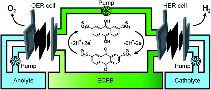
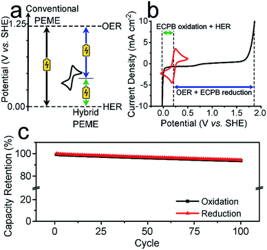
Previously, we introduced the concept of the electron-coupled proton buffer (ECPB), which allows water electrolysis to be split into two separate steps (Fig. 1) using inorganic polyoxometalates.8–11 The protons and electrons released during water oxidation are intercepted by the ECPB, preventing hydrogen evolution (eqn (1)). Subsequent oxidation of the ECPB leads to molecular hydrogen production, separating gas evolution in both time and space (eqn (2)). This approach results in two low-potential steps instead of the single large input required in traditional water splitting. The relative magnitudes of the two potentials required is affected by the redox potential of the ECPB with respect to the oxygen evolution and hydrogen evolution reactions (OER and HER). In the absence of overpotentials, these two voltages sum to be equal to that required for conventional water electrolysis (Fig. 2a).
 | (1) |
| rECPB[H2] → ECPB + H2 | (2) |
A major feature of this system, important for application, is that by breaking up the water splitting process into two steps, the issues surrounding gas crossover can be mitigated. Removing the risk of explosive gas mixtures forming results in an inherently safer system design. Separating gas production also provides benefits to gas purity, thereby reducing the need for further purification. The previously reported inorganic ECPBs worked well for decoupling gas evolution reactions during water splitting, but suffered from high cost and low specific energy due to the presence of transition metals (Mo, W).8,10 We hypothesised that organic ECPBs could act as low-cost, high specific energy hydrogen storage media, improving upon the heavier polyoxometalate analogues. Previously, we reported the use of hydroquinone sulfonate as an effective proof-of-principle for organic ECPBs, but unfortunately the storage capacity depleted at a rate of 1% per full oxidation–reduction cycle.9 The reversible redox properties of cheap organic molecules have made them a recent focus for redox flow battery technology, with several successful applications.12–17 In 2014, Huskinson et al. reported the inclusion of anthraquinone-2,7-disulfonic acid (AQDS) as the negolyte (negative electrolyte) of a redox flow battery alongside a Br2/Br− posolyte (positive electrolyte), which displayed impressive performance and reversibility.12 The electrochemical properties of AQDS, coupled to its high water solubility, make it an ideal candidate for ECPB applications. The cost of AQDS is only 1.02% of the previously reported silicotungstic acid, improving the economic viability of the ECPB system (cost calculations in the ESI†).
Here we describe the application of anthraquinone-2,7-disulfonic acid into a laboratory-scale, hybrid proton exchange membrane electrolyser (PEME) system, where the two gas evolution reactions are no longer coupled. We demonstrate that the device performs at comparable standards to the state-of-the-art in PEME technology, but with the added benefits of being able to extend the HER rate beyond the limits of the OER, and being inherently safer by design.
Results and discussion
To be an effective ECPB, a compound must be soluble in water, have reversible redox behaviour at potentials between the OER and HER, and be stable in both the oxidised and reduced forms. It must also buffer the pH during electrolysis, so that a pH gradient does not develop within the cell. Therefore, to examine the ability of AQDS to reversibly uptake protons and electrons during water splitting, a 25 mM solution was prepared in 1 M sulfuric acid for electrochemically analyses. The cyclic voltammogram (CV) showed a reversible redox wave centred at 0.214 V vs. standard hydrogen electrode (SHE), which was stable under extended cycling (Fig. 2b and S1†).The reversibility of the redox couple was further investigated by the complete reduction and oxidation of the AQDS solution in a two-compartment H-cell (Fig. S2†), observing the charge capacity over 100 cycles. Fig. 2c shows the charge retention of the oxidation/reduction cycles normalised against the charge passed during the first reduction. The charge capacity shows an overall decrease of 5.75% over 100 cycles, equating to less than 0.06% per cycle. This is an improvement of almost 17 times on the previously published hydroquinone sulfonate (which showed a loss of approximately 1.00% per cycle).9 The gases produced at the counter electrode during the reduction or oxidation of the AQDS were measured volumetrically and compared to the theoretical volumes of O2/H2 calculated from the charge passed (Fig. S3†). The measured volumes were consistent with the theoretical values, displaying approximately 100% faradaic efficiency (FE). The gases evolved during the reduction and oxidation of AQDS were analysed by gas chromatography headspace analysis (GCHA), and confirmed to be O2 and H2, respectively.
Hybrid PEME
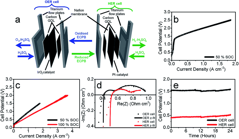
Having confirmed anthraquinone-2,7-disulfonic acid to be suitable as an ECPB, it was then implemented into a PEM electrolyser system where the oxygen evolution and hydrogen evolution reactions would take place in completely separate cells. This concept can be viewed as a hybrid between PEM water electrolysis and flow battery technology, whereby the ECPB redox couple acts as both the negolyte during the oxygen evolution reaction, and the posolyte during hydrogen evolution.As such, the architecture of the hybrid device borrows from both of these existing technologies.1,18–22 This concept was explored by building two separate PEME cells to run in tandem (schematic in Fig. 3a, photograph in Fig. S4†). The first cell would oxidise water, forming oxygen, whilst reducing the ECPB (defined as the OER cell). The second cell would re-oxidise the ECPB and reduce protons, forming hydrogen (the HER cell). In this setup, the gases are produced in separate cells, thereby mitigating any gas crossover issues. The use of a dual cell setup adds to the capital costs of the system, though these may potentially be offset by longer component lifetimes thanks to the lower individual cell voltages and reduced degradation from reactive oxygen species. The active surface area of each cell was 12.96 cm2, with catalyst used only for the gas evolving electrodes. As with the small scale tests, 1 M H2SO4 was used as the electrolyte in the gas evolving sections of the cells. A solution of 0.5 M AQDS in 1 M H2SO4 was used as the ECPB mediator being pumped between the two cells, at a state of charge (SOC) of 50% unless otherwise stated. All solutions were heated to 50 °C and circulated at a flow rate of 250 mL min−1.
The performance of this hybrid device can best be observed through the polarisation curves of the individual cells, showing the current response at increasing potential (Fig. 3b and c). As the charge passed during ECPB oxidation is directly proportional to the volume of hydrogen evolved, current can be viewed as an H2 production rate. The onset of the OER was at approximately 1.30 V, reaching a current density of 1.00 A cm−2 at 2.01 V (Fig. 3b). The onset of the HER was at just over 0.20 V, with a current density of 1.00 A cm−2 achieved at just 0.96 V (Fig. 3c, black line). Though this results in a higher overall voltage than in state-of-the-art PEME cells, crucially this device allows water splitting to be carried out even at low current densities or elevated pressure without risk of gas crossover.5,7,19 This alleviates issues surrounding explosive gas mixtures forming during PEME operation, resulting in an inherently safer system design. On top of the safety aspect, the mitigation of gas crossover results in purer product gases whilst also extending the lifetime of the cell components (by reducing cell degradation from reactive oxygen species).5,7
This device is therefore well suited for use alongside the fluctuating energy outputs associated with renewable sources, where the current may often drop to lower ranges. Furthermore, the hydrogen evolution reaction (HER) is no longer limited by the oxygen evolution (OER), and the two processes can temporarily proceed at different rates. This offers a more flexible approach to device operation, with the ability to trickle-charge the ECPB during times of low energy production before releasing H2 at a faster rate and with a significantly lower energy input. This was demonstrated by operating the HER cell at 100% state of charge (i.e. the AQDS is fully reduced), where a maximum current density of 3.71 A cm−2 was achieved at 2.00 V (Fig. 3c, shown in red; flow rate of AQDS increased to 400 mL min−1 to mitigate mass transport issues).
The polarisation curves of the two cells hint at increased cell resistances when compared to conventional high performance PEM electrolysers. This was confirmed using potentiostatic electrochemical impedance spectroscopy (PEIS), where the ohmic resistances of the OER and HER cells were found to be 0.408 Ω cm2 and 0.492 Ω cm2, respectively (Nyquist plots in Fig. 3d). This is higher than would be expected for a state-of-the-art PEME, and represents an area that could be improved upon in future cell design. Due to the separation of the gas evolving reactions, there are less stringent requirements on the permeability of the membrane, which could potentially be replaced by a cheaper, more conductive alternative. The activation overpotentials were also relatively high, which is partially due to the relatively low catalyst loading of the gas evolving electrodes (1.00 mg cm−2 IrO2 and 0.30 mg cm−2 Pt for the OER and HER electrodes, respectively). The activation overpotentials of the reduction and oxidation of AQDS could also be minimised through the use of a suitable catalyst, providing scope to improve the performance further. Full impedance data can be found in the ESI (Table S1†), along with the equivalent electric circuit used for data-fitting.
Gas measurements were used to verify the operation of the cells, comparing the measured and expected volumes of gas to give the FE. These measurements displayed >99% efficiency, as expected from results recorded in the initial screening process (Tables S2 & S3†).
These measurements were also used to determine the energy efficiency of the cell processes, through comparing the energy required to produce a volume of hydrogen against the energy theoretically obtained through its combustion (using the higher and lower heating values of hydrogen (HHV and LHV), 285.60 kJ mol−1 and 237.35 kJ mol−1, respectively). This gave an efficiency of 62.63% (HHV) or 52.05% (LHV) for the two electrolyser cells operating at 0.50 A cm−2 (Table S4† with accompanying calculations). This is lower than the energy efficiencies typically seen in state-of-the-art PEMEs (up to 90% vs. the HHV), and could be improved by lowering the ohmic resistances of the cell components.1,19 Decoupling the gas evolution reactions over two separate cells should theoretically result in increased gas purity in our device. This was confirmed through gas chromatography, with no H2 or O2 crossover seen in the product gas streams (Fig. S5†).
The operational stability of the device was examined by running both cells at a current of 0.25 A cm−2 for 24 hours, and measuring the potential required for each cell (Fig. 3e). There was an increase in voltage of 33 mV for the OER cell and 103 mV for the HER over the 24 hour period (passing approx. 280![[thin space (1/6-em)]](https://www.rsc.org/images/entities/char_2009.gif) 000 C of charge through each cell). This increase has been attributed to electro-osmotic drag, decreasing the concentration (and therefore pH) of the HER catholyte solution over time.6 This was evidenced by an increase in volume of the catholyte solution during measurement, and simultaneous decrease in the anolyte volume.
000 C of charge through each cell). This increase has been attributed to electro-osmotic drag, decreasing the concentration (and therefore pH) of the HER catholyte solution over time.6 This was evidenced by an increase in volume of the catholyte solution during measurement, and simultaneous decrease in the anolyte volume.
Conclusions
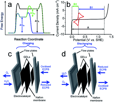
Anthraquinone-2,7-disulfonic acid (AQDS) has successfully been implemented into a hybrid PEM electrolyser system, capable of producing oxygen and hydrogen at completely separate times and locations. This is a major safety advance in electrolytic water splitting due to the greatly reduced risk of explosive gas mixtures forming, with further benefits in the increased purity of the product gases. The hybrid electrolyser produced currents of 1.00 A cm−2 at a combined voltage of 2.97 V, which could be improved through the development of the cell design and incorporation of suitable catalysts. The two-step process shown here allows the OER and HER rates to be independent of one another, offering a greater degree of operational flexibility. By charging the AQDS solution to 100% SOC, the HER cell was able to produce hydrogen at a current density of 3.71 A cm−2 at a voltage of just 2.00 V. The performance of the AQDS electrolyser was very promising for a first generation device, with further scope to optimise the system in the future. The increased cost of dual cell setup may be minimised in the future through selection of cheaper cell components. Splitting up the gas evolution reactions results in less stringent demands on the gas impermeability of the membranes, opening the possibility of using cheaper, more conductive alternatives. The higher purity H2 produced would also remove the need for downstream purification, reducing costs for applications where ultra-high purity hydrogen is required, such as in semiconductor fabrication.23 Given that conventional electrolysers must run at high current densities to prevent degradation or the production of explosive gas mixtures, the use of such systems with renewables often requires back up battery systems. This added cost means that our new approach promises not only to be more robust, but economically competitive.An interesting prospective avenue of work could involve modifying this system to have the additional function of a battery discharge, thereby allowing the option of H2 production or electrical storage. This could be achieved by having a discharge step similar to a metal–air battery, where the reduced ECPB would be oxidised while reducing O2 (Fig. 4).24
The system could then be operated in two ways. The first would be the operation described above, where overall water splitting would be conducted in two steps to produce O2 and H2 (Fig. 4a and b, pathway B1 + B2; eqn (4) and (5)). The product gases could then be recombined in a fuel cell to produce electricity (pathway A; reverse of eqn (3)).
 | (3) |
 | (4) |
| rECPB[H2] → ECPB + H2 | (5) |
The second mode would involve the same initial step (Fig. 4, pathway B1; eqn (4)). Instead of then proceeding with pathway B2 to produce H2, the reduced ECPB could be oxidised while reducing O2 (Fig. 4, reverse of pathway B1; reverse of eqn (4)), producing electricity in the process. This effectively removes the need for a fuel cell, and eliminates the risks associated with H2 storage and handling.
Methods
25 mM AQDS solutions were prepared in 1 M H2SO4, with all measurements performed at room temperature unless otherwise stated. Cyclic voltammetry experiments were carried out in a one-compartment, three-electrode setup, with glassy carbon working electrode, Ag/AgCl (saturated KCl) reference electrode, and Pt-mesh counter electrode. Chronoamperometry experiments were carried out using the setup shown in Fig. S1.† PEME experiments were performed with all solutions heated to 50 °C and circulated at 250 mL min−1, with the AQDS solution at 50% SOC (unless otherwise stated). Full experimental methods for the hybrid electrolyser can be found in the ESI.†Conflicts of interest
The authors declare no competing financial interests.Author contributions
L. C. devised the concept. N. K. performed all experimental work on the electrochemical screening and hybrid electrolyser cell. G. C. and J. J. C. contributed valuable assistance in electrochemical experiments and cell design. All authors contributed to the discussion. N. K. and L. C. wrote the manuscript. L. C. supervised the overall project.Acknowledgements
This work was supported by the EPSRC grants (No. EP/J015156/1; EP/L023652/1; EP/I033459/1; EP/J015156/1; EP/K023004/1; EP/L023652/1; EP/K038885/1), BBSRC grant BB/M011267/1. L. C. thanks the Royal Society/Wolfson Foundation for a Merit Award and the ERC for an Advanced Grant (ERC-ADG, 670467 SMART-POM). We thank Dr Mark Symes, Dr Edward Brightman, and Dr Leanne Bloor of the School of Chemistry, University of Glasgow for their intellectual contributions to this work.References
- M. Carmo, D. L. Fritz, J. Mergel and D. Stolten, Int. J. Hydrogen Energy, 2013, 38, 4901–4934 CrossRef CAS.
- I. Staffell and P. Dodds, The role of hydrogen and fuel cells in future energy systems, H2FC SUPERGEN, London, UK, 2017 Search PubMed.
- N. Armaroli and V. Balzani, ChemSusChem, 2011, 4, 21–36 CrossRef CAS PubMed.
- F. Gutiérrez-Martín and I. Guerrero-Hernández, Int. J. Hydrogen Energy, 2012, 37, 1151–1161 CrossRef.
- S. A. Grigoriev, V. I. Porembskiy, S. V. Korobtsev, V. N. Fateev, F. Auprêtre and P. Millet, Int. J. Hydrogen Energy, 2011, 36, 2721–2728 CrossRef CAS.
- M. Schalenbach, M. Carmo, D. L. Fritz, J. Mergel and D. Stolten, Int. J. Hydrogen Energy, 2013, 38, 14921–14933 CrossRef CAS.
- F. Barbir, Sol. Energy, 2005, 78, 661–669 CrossRef CAS.
- M. D. Symes and L. Cronin, Nat. Chem., 2013, 5, 403–409 CrossRef CAS PubMed.
- B. Rausch, M. D. Symes and L. Cronin, J. Am. Chem. Soc., 2013, 135, 13656–13659 CrossRef CAS PubMed.
- B. Rausch, M. D. Symes, G. Chisholm and L. Cronin, Science, 2014, 345, 1326–1330 CrossRef CAS PubMed.
- L. G. Bloor, R. Solarska, K. Bienkowski, P. J. Kulesza, J. Augustynski, M. D. Symes and L. Cronin, J. Am. Chem. Soc., 2016, 138, 6707–6710 CrossRef CAS PubMed.
- B. Huskinson, M. P. Marshak, C. Suh, S. Er, M. R. Gerhardt, C. J. Galvin, X. Chen, A. Aspuru-Guzik, R. G. Gordon and M. J. Aziz, Nature, 2014, 505, 195–198 CrossRef CAS PubMed.
- B. Yang, L. Hoober-Burkhardt, F. Wang, G. K. Surya Prakash and S. R. Narayanan, J. Electrochem. Soc., 2014, 161, A1371–A1380 CrossRef CAS.
- F. Pan and Q. Wang, Molecules, 2015, 20, 20499–20517 CrossRef CAS PubMed.
- K. Lin, Q. Chen, M. R. Gerhardt, L. Tong, S. B. Kim, L. Eisenach, A. W. Valle, D. Hardee, R. G. Gordon, M. J. Aziz and M. P. Marshak, Science, 2015, 349, 1529–1532 CrossRef CAS PubMed.
- Y. Ding and G. Yu, Angew. Chem., Int. Ed., 2016, 55, 4772–4776 CrossRef CAS PubMed.
- B. Yang, L. Hoober-Burkhardt, S. Krishnamoorthy, A. Murali, G. K. S. Prakash and S. R. Narayanan, J. Electrochem. Soc., 2016, 163, A1442–A1449 CrossRef CAS.
- P. Millet, R. Ngameni, S. A. Grigoriev, N. Mbemba, F. Brisset, A. Ranjbari and C. Etiévant, Int. J. Hydrogen Energy, 2010, 35, 5043–5052 CrossRef CAS.
- G. Chisholm, P. J. Kitson, N. D. Kirkaldy, L. G. Bloor and L. Cronin, Energy Environ. Sci., 2014, 7, 3026–3032 CAS.
- M. L. Perry and A. Z. Weber, J. Electrochem. Soc., 2016, 163, A5064–A5067 CrossRef CAS.
- W. Wang, Q. Luo, B. Li, X. Wei, L. Li and Z. Yang, Adv. Funct. Mater., 2013, 23, 970–986 CrossRef CAS.
- A. Z. Weber, M. M. Mench, J. P. Meyers, P. N. Ross, J. T. Gostick and Q. Liu, J. Appl. Electrochem., 2011, 41, 1137–1164 CrossRef CAS.
- Fulfilling The Rising Demand For High Purity Hydrogen, https://compoundsemiconductor.net/article/89215-fulfilling-the-rising-demand-for-high-purity-hydrogen.html, accessed 4 August 2017.
- L. Jörissen, J. Power Sources, 2006, 155, 23–32 CrossRef.
Footnote |
| † Electronic supplementary information (ESI) available. See DOI: 10.1039/c7sc05388f |
| This journal is © The Royal Society of Chemistry 2018 |


