3D bioprinting of dual-crosslinked nanocellulose hydrogels for tissue engineering applications†
Marzieh
Monfared
a,
Damia
Mawad
 *b,
Jelena
Rnjak-Kovacina
 c and
Martina H.
Stenzel
 *a
*a
aSchool of Chemistry, UNSW Sydney, NSW 2052, Australia. E-mail: m.stenzel@unsw.edu.au
bSchool of Materials Science and Engineering, UNSW Sydney, NSW 2052, Australia. E-mail: d.mawad@unsw.edu.au
cGraduate School of Biomedical Engineering, UNSW Sydney, NSW 2052, Australia
First published on 7th June 2021
Abstract
Hydrogels based on cellulose nanofibrils (CNFs) have been widely used as scaffolds for biomedical applications, however, the poor mechanical properties of CNF hydrogels limit their use as ink for 3D bioprinting in order to generate scaffolds for tissue engineering applications. In this study, a dual crosslinkable hydrogel ink composed of a poly(ethylene glycol) (PEG) star polymer and 2,2,6,6-tetramethyl-1-piperidinyloxy (TEMPO)-oxidized nanocellulose fibers (CNFs) is presented. As the resulting hydrogel had low structural integrity, at first crosslinking of CNFs was introduced by Ca2+. Strong physical interactions between CNFs and Ca2+ cations allowed easy regulation of the viscosity of the inks for extrusion printing raising the solution viscosity by more than 1.5 times depending on the amount of Ca2+ added. The resulting hydrogel had high structural integrity and was further stabilized in a second step by photo crosslinking of PEG under visible light. In only a few seconds, hydrogels with Young's modulus between ∼10 and 30 kPa were obtained just by altering the CNF and Ca2+ content. 3D printed hydrogels supported fibroblasts with excellent cell viability and proliferation. The dual crosslinkable hydrogel ink herein developed is versatile, easy to prepare, and suitable for 3D printing of bioscaffolds with highly tailored viscoelastic and mechanical properties applicable in a wide range of regenerative medicines.
1. Introduction
3D printing of biological materials, including cells, growth factors, natural polymers, and other biological compounds is increasingly explored as a means to restore tissues and organs of a body.1,2 Mimicking the structure and morphology of tissues and organs with high accuracy is one of the main advantages of 3D bioprinting compared to other fabrication technologies used in tissue engineering.3 Extrusion-based 3D bioprinting is one of the most common techniques to print polymer-based solutions that have cells at accurate locations. The cells can be placed in 3D space via two common methods. Firstly, the polymeric solution can be printed and eventually seeded with cells following printing. Secondly, the solution contains cells and they are entrapped during the printing process.4 The viscous polymeric solution is hereafter referred to as ink injected from a micro-needle extrusion nozzle with the aim to print the desired patterned scaffold, a process which can be combined with biological components to achieve suitable cell proliferation.5–7 However, designing the ink is still one of the most challenging aspects of 3D bioprinting.8,9 The challenge is to adjust the ink properties such as its viscosity to achieve material properties suitable for biological systems. This has so far limited the current number of 3D printed materials in clinical applications.10 Hydrogels are the most prominent class of printable materials as they provide numerous advantages for tissue engineering and cell delivery applications, such as tunable degradability, cytocompatibility, and tissue-like elastic properties.5 The attraction of hydrogels lies in their highly swollen three-dimensional network, comparable to the environment of the native tissue.11A suitable hydrogel ink must be viscous enough to maintain its shape during printing and must be crosslinkable to retain its 3D structure after printing.12 The hydrogel ink can be strengthened either with viscosity-enhancing agents like methylcellulose or reinforced materials like hydroxyapatite in order to improve its viscosity and thus rendering it suitable for 3D printing.5,10,12 Crosslinking using chemical or physical approaches can be employed in order to maintain the structural integrity of the printed scaffold. A large variety of chemical crosslinking approaches has been developed, enabling the hydrogel properties to be fine-tuned. However, care needs to be taken to avoid the production of cytotoxic intermediates and harmful by-products.13,14 Physical crosslinking on the other hand produces no cytotoxic species, but it is difficult to control the hydrogel properties.15 Furthermore, this process can only be applied to polymers with molecular structures that allow physical interactions such as hydrophobic interactions or hydrogen and ionic bonding, such as alginate ionic crosslinking with Ca2+.16 The advantage is that the dynamics of physical crosslinks allow response to changes in the environment. Thus, combining physical and chemical crosslinking can offer superior performances not attainable by individual methods.17
Recently, nanocellulose (NC) has received significant attention as a building block of materials as it can be obtained from renewable sources, while it also displays exceptional properties including high elastic modulus, low density, high specific surface area, easy surface modification, and biocompatibility.18,19 This led to the development of a large number of hydrophilic and hydrophobic composite matrices and hybrid materials such as hydrogels and aerogels based on nanocellulose, either in the form of cellulose nanocrystals (CNCs) or cellulose nanofibers (CNFs).20 CNFs as the main building block of hydrogels have been extensively used as a scaffold material for biomedical applications due to their low cytotoxicity and their structural similarity to the extracellular matrix. However, their use in 3D bioprinting is limited as these hydrogels usually display poor mechanical properties.21 Moreover, CNF hydrogels based on electrostatic interactions can be dissociated in solutions of high ionic strength resulting in low mechanical stability.22 To our knowledge, there have been no attempts to print nanocellulose scaffolds with highly tunable mechanical properties and stability in the wet state via combining both chemical and physical crosslinking. We address this gap here.
In this study, we designed a hydrogel ink based on poly(ethylene glycol) (PEG) hydrogels reinforced with cellulose nanofibers with a wide range of viscoelastic and mechanical properties.
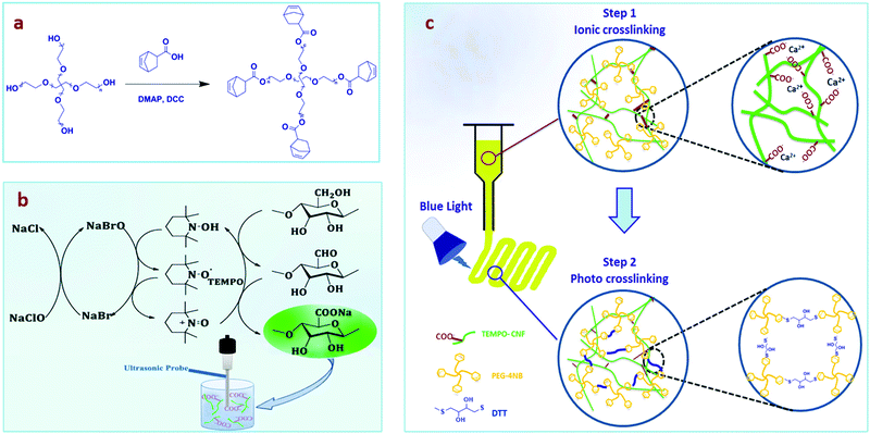
We utilized a dual crosslinking approach by preparing an interpenetrating network, which includes (i) the cellulose nanofiber network prepared by ionic crosslinking with calcium ions (Ca2+) before printing to enhance the viscosity of the ink, and (ii) a PEG hydrogel formed after crosslinking by the thiol–ene photoreaction of norbornene groups, introduced in a 4-arm PEG star polymer, and dithiothreitol (DTT) (Fig. 1a). The bioactive, water-soluble form of vitamin B2 (riboflavin 5′-monophosphate, FMN) was used as the photoinitiator for the formation of the PEG network due to its cytocompatibility and higher water solubility compared with other chemical photoinitiators.23 Furthermore, vitamin B2 allows crosslinking under blue LED light making this process easier to set up instrumentally, while visible light is also more cytocompatible than UV light.23–25 2,2,6,6-Tetramethyl-1-piperidinyloxy (TEMPO)-oxidized nanocellulose fibers (TEMPO-CNFs) or shortly CNFs were synthesized by introducing carboxylate groups into microcrystalline cellulose using established procedures (Fig. 1b).26 The negative charge on CNFs plays a key role in the interaction with Ca2+ as the strength of the electrostatic interaction will regulate the stiffness of the formulated inks (Fig. 1c), therefore the viscosity was optimized by the addition of CaCl2. After 3D printing, the PEG-CNFs were chemically crosslinked under visible light.27 The mechanical strength, printability, and cytocompatibility of PEG-CNF hydrogels for 3D bioprinting were studied.
This ink was used to print the scaffolds and the cells were subsequently seeded on the surface; however, this ink has the potential to be mixed with cells during the bioprinting process, although this was not explored here.
2. Experimental
2.1. Materials
4-Arm poly(ethylene glycol) (PEG) (20 kDa) was purchased from JenKem Technology. Fetal bovine serum (FBS) and an Alamar blue assay kit (DAL 1025) were purchased from Invitrogen. All other chemicals were obtained from Sigma-Aldrich. L929 fibroblast cells were obtained from CellBank Australia.2.2. Methods
2.3. Ink formulation
Inks with different formulations were prepared as listed in Table 1. Mixtures of 1 mL were prepared by dissolving 4PEG-NB (100 mg, 0.0049 mmol), DTT (1.5 mg, 0.0098 mmol), and FMN (0.045 mg, 0.0001 mmol) in CNF aqueous stock solution (4.95 wt%). The stock solution of CNFs was diluted by adding Milli-Q water to prepare different concentrations according to Table 1, followed by sonication for 10 min. CaCl2 was added to the previous mixtures at two different molar ratios between the Ca2+ and the carboxyl group of CNFs. The code, xNF, in Table 1 indicates the weight percentage of CNFs while the number before Ca shows the ratio between Ca2+ and the carboxyl groups of CNFs in the ink formula. The photo reaction of all mixtures was carried out under blue light (460 nm and 25 mW cm−2). The aqueous solution of 4PEG-NB (100 mg, 10 wt%), 1.5 mg DTT, and 0.045 mg FMN in 1 mL Milli-Q water has been prepared as a control (PEG-10).| Precursor code | 2NF-0Ca | 3NF-0Ca | 4NF-0Ca | 2NF-0.5Ca | 3NF-0.5Ca | 4NF-0.5Ca | 2NF-1Ca | 3NF-1Ca | 4NF-1Ca |
|---|---|---|---|---|---|---|---|---|---|
| CNFs (wt/v%) | 2 | 3 | 4 | 2 | 3 | 4 | 2 | 3 | 4 |
| Ca2+/COO− (molar ratio) | 0 | 0 | 0 | 0.5 | 0.5 | 0.5 | 1 | 1 | 1 |
| Ca2+ (mM) | 0 | 0 | 0 | 12.7 | 19 | 25.4 | 25.4 | 38.1 | 50.8 |
2.4. PEG-CNF hydrogel fabrication
The above precursor solutions were mixed using two syringes connected using a female–female luer lock connector. The solution was pushed back and forth (50 times) between the two syringes, followed by sonication for 10 min. The mixture was kept in the dark, and covered by aluminum foil to avoid exposure to light. CaCl2 was then added to the precursor according to Table 1 and mixed as well. For the photo hydrogelation, the precursor solution was poured into a polydimethylsiloxane (PDMS) mold (8 mm diameter and 2 mm height) and exposed to blue light (460 nm and 25 mW cm−2) for 3 min.2.5. Physico-chemical hydrogel characterization
 | (1) |
 | (2) |
 | (3) |
2.6. 3D-printing
PEG-CNF printing was carried out on a customized LulzBot mini 3D-printer through layer-by-layer deposition of ink onto a Petri dish. 3D constructs were designed in an Autodesk fusion 360 and converted into a G-code by Slic3r software and then uploaded into the printer SD card. The ink was loaded into a 1 mL syringe at room temperature with a stainless steel needle (Nordson, USA). A 3D scaffold model with dimensions of 10 mm width, 10 mm length, and 4 mm height was designed with a 2 mm filament grid. Parameters optimized during the printing process included the needle gauge size (20–23 G) and the printing speed (1–4 mm s−1). The printed scaffolds were then photo-crosslinked by exposure to blue light (460 nm and 25 mW cm−2) for 3 min.2.7. Cell viability and metabolic activity
L929 fibroblast cells were cultured in phenol red-free DMEM supplemented with 10% (v/v) fetal bovine serum (FBS) and 1% (v/v) penicillin and streptomycin incubated at 37 °C with 5% CO2 and 95% humidity. Cytotoxicity tests were performed via an indirect cytotoxicity test according to ISO standard 10993-5:2009(E), by culturing L929 fibroblasts in the extract solution of the PEG-CNF hydrogels.29 L929 fibroblasts were seeded on a tissue culture plate (96-well) at 3000 cells per well and in 10% FBS containing DMEM (200 μL) for 24 h. To obtain the hydrogel extract, the photo crosslinked hydrogel discs (10 mm diameter and 2 mm height) were incubated in DMEM (1 mL) at 37 °C and 5% CO2 for 24 h using sterile cell culture plates. After 24 h, the cell culture medium of the cells was replaced with this hydrogel extract solution, followed by 24 and 48 h incubation. The cells were cultured in media and media containing 20% DMSO, considered as the negative and positive controls, respectively. The metabolic activity was measured by Sulforhodamine B (SRB) assay using a Bio-rad BenchmarkTM microplate reader at an absorption wavelength of 570 nm. The experiments were repeated 3 times, with 4 samples tested in each experiment. An Alamar blue assay was conducted to study the metabolic activity of cells seeded on the photo crosslinked hydrogels. Using a pipette, L929 cells were seeded on top of both the disc shape hydrogel formed in the PDMS mold and the grid shaped hydrogel printed in the 3D printer (n = 3). The cell density was 0.04 × 10⁶ and 0.12 × 10⁶ cells per disc and grid scaffold respectively and unseeded structures (disc and scaffold) were used as controls. Gelatin (0.5 wt%) was incorporated into the ink to support cell interactions. The metabolic activity of the cells was analyzed at 1, 3, 6, 10, and 14 d after culture. The discs and square block bioprinted structures were incubated in 12-well plates for 5 h with 10% Alamar blue. After incubation, the printed scaffolds were moved to a fresh 12-well plate with new media and the Alamar blue solution was aliquoted into a non-binding 96-well black plate, read for fluorescence at excitation 540/35 and emission 600/40, using a Synergy™ HTX Multi-Mode Microplate Reader (BioTek Instruments, USA).On day 3 and day 14 of culture, the bioprinted structures were removed from media, washed gently with PBS, and incubated in 2 mL of 2 μM Calcein AM for 15 minutes at 37 °C with 5% CO2. Samples were washed with PBS twice and imaged using a Leica TCS SP2 Confocal Microscope, with excitation at 488 nm and emission at 505–535 nm. A z-stack of approximately 800 μm was created from a random area of the scaffold with a stack of every 10 μm and averaged to create a single image using ImageJ.
2.8. Scanning electron microscopy (SEM)
The morphological structure of PEG-CNF hydrogels was observed using a field-emission scanning electron microscope (FE-SEM). Samples were washed using PBS and immersed in fixing solutions of 2.5% glutaraldehyde (GA) in 0.1 M sodium cacodylate buffer (SCB) for 1 hour at room temperature. Samples were washed with 0.1 M SCB and transferred to 1% osmium tetroxide solution, following dehydration using a graded ethanol series in steps of 30%, 50%, 70%, 80%, 90%, 95%, 100%, 100%, and 100% ethanol. Each immersion step was performed for 15 min to allow for ethanol diffusion into the gels. All washing steps were performed in Pelco Biowave® Pro+. The samples were then dried using a Tousimis Autosamdri®-815 critical point dryer. The dried samples were cut using a razor blade and mounted onto the 25 mm SEM stubs with carbon tape, sputter-coated with platinum, and imaged using NanoSEM 230 at an accelerating voltage of 5 kV to evaluate the morphology and microstructure. The 3D bioprinted samples at day 3 and day 14 of culture were used for SEM analysis.2.9. Statistical analyses
All data are expressed as mean ± standard deviation (SD) unless stated otherwise. Statistical analyses were performed using GraphPad Prism. The statistically significant differences were determined by one- or two-way analysis of variance (ANOVA), and the Tukey or Sidak's post-test (ns = nonsignificant, *p < 0.05, **p < 0.01, ***p < 0.001, and ****p < 0.0001). Statistical significance was accepted at p < 0.05.3. Results and discussion
3.1. Synthesis and characterization of CNFs
CNFs were prepared by TEMPO-mediated oxidation of microcrystalline cellulose followed by ultrasonication treatment.26 The amount of carboxylate groups on CNFs was determined by pH titration and found to be 1.27 mmol per gram of CNFs (Fig. S3a, ESI†). Visual observation of the CNF aqueous solution showed a significant improvement in the transparency of the solution after ultrasonication (Fig. S3c–e, ESI†), indicating that the CNFs are well dispersed. TEM confirmed the formation of nano-sized fibers disintegrated from microcrystalline cellulose (nanofiber diameter, ∅ ≈ 10 nm) (Fig. 2a and b). The hydrodynamic diameter Dh in aqueous solution as obtained with DLS results was measured to be 115.8 ± 2.3 nm at pH 7.1, with a size distribution (PDI = 0.4) from three repeated experiments (Fig. S3b, ESI†). DLS can only provide some information on aggregation or the absence thereof, but cannot be used as a technique to measure the size of the fibers with their high aspect ratio.30 In this case, DLS confirmed that the CNFs are in discrete nano form and are not significantly agglomerated. The zeta potential of −32.9 ± 1.8 mV confirmed the abundance of negatively charged carboxyl groups on the surface of CNFs, which assist dispersion and electrostatic interactions with positively charged Ca2+. Although binding in carboxylated glucose (log![[thin space (1/6-em)]](https://www.rsc.org/images/entities/char_2009.gif) K ∼ 2) is lower than that of the strongly citrate one (log
K ∼ 2) is lower than that of the strongly citrate one (log![[thin space (1/6-em)]](https://www.rsc.org/images/entities/char_2009.gif) K ∼ 3.5), the close vicinity of several carboxyl groups can increase the binding constant.31 It needs however to be considered that the mixture will always contain Ca2+ ions that are bound to one CNF (acting as a counterion), to two CNFs (acting as a crosslinker), as well as free Ca2+.32
K ∼ 3.5), the close vicinity of several carboxyl groups can increase the binding constant.31 It needs however to be considered that the mixture will always contain Ca2+ ions that are bound to one CNF (acting as a counterion), to two CNFs (acting as a crosslinker), as well as free Ca2+.32
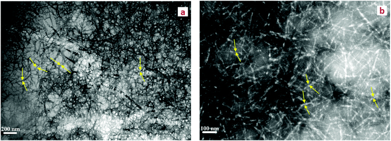 | ||
| Fig. 2 (a and b) TEM images of cellulose nanofiber dispersion after TEMPO-mediated oxidation and ultra-sonication. The fibers are highlighted by yellow arrows. | ||
3.2. Rheological evaluation
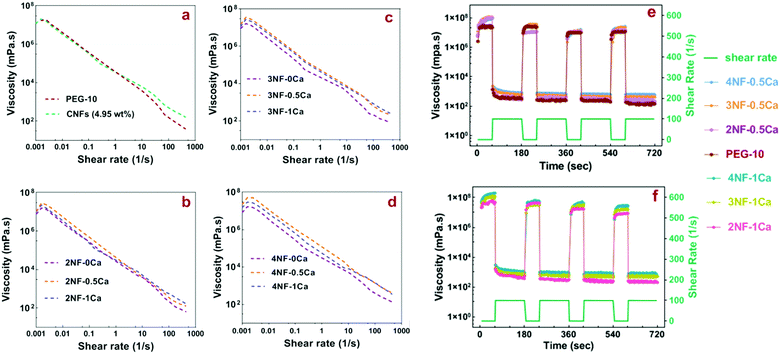
During the 3D printing process, the ink is subject to shear stress. Thus evaluation of the rheological properties can give insight into the flow behavior of the material under extrusion,33 which is important when considering that nanocellulose is anisotropic and can potentially align during flow.34,35 The precursors, which are the mixture before thiol–ene crosslinking, containing 4PEG-NB, DTT, RF, CNFs and CaCl2, were prepared according to Table 1. The physical crosslinking of CNFs via ionic interactions with Ca2+ was utilized as the first gelation step in the ink preparation, to increase the viscosity and improve the shape fidelity of the PEG-CNFs. The shear-thinning behavior of PEG-CNF precursors as traced over a shear rate of 0.001–1000 s−1 is shown in Fig. 3(a–d) (for better visibility the shear thinning results of all hydrogel mixtures were separated into different graphs). The PEG-10 solution and all PEG-CNF groups showed a shear-thinning behavior that is typical for disentangling networks in response to the action of the shear stress.36 Shear-thinning, defined as a non-Newtonian behavior, causes the ink viscosity to decrease as the shear rate increases and enables its extrusion through the nozzle with applied pressure.37 The behavior of the 4.95 wt% CNF aqueous solution (Fig. 3a) is similar to the shear thinning behavior previously reported for nanocellulose.38 A shoulder is visible at a low shear rate (<0.003 s−1) in all diagrams (Fig. 3a–d), and is attributed to the static yield stress. This is an important parameter in defining a suitable ink for extrusion-based printing, as it is the stress required to make the ink flow from rest.10,37Fig. 3a–d and Fig. S4 (ESI†) show that the zero shear viscosity increased after adding CNFs to the PEG solution, as 2NF-0Ca, 3NF-0Ca and 4NF-0Ca groups showed higher values (∼1.2–1.5 × 10⁴ Pa s) than PEG-10 (∼0.5 × 10⁴ Pa s), confirming the reinforcing effect of CNFs. Furthermore, samples with higher content of CNFs had a higher viscosity, for example 4NF-0Ca exhibited a ∼1.3 times increase in viscosity compared to 2NF-0Ca. Introducing Ca2+ into the PEG-CNF solutions resulted in a further increase in the zero shear viscosity as 2NF-0.5Ca, 3NF-0.5Ca, and 4NF-0.5Ca showed ∼1.5–2 times higher viscosity compared to the samples without Ca2+, i.e. 2NF-0Ca, 3NF-0Ca, and 4NF-0Ca. However, increasing the ratio of Ca2+ to CNFs from 0.5 to 1 did not appear to have a significant effect on the viscosity. A similar trend was observed at higher shear rates. The rheology data highlight the importance of CNFs and Ca2+ concentration in increasing the viscosity of the formulated inks and can therefore be used to dial-in the most suitable rheological behavior.
It is worth noting though that shear thinning by itself does not define the printability, as other parameters will affect it too. Examples of these parameters include ink viscosity, composition/concentration, nozzle variables, filament dimensions, printing speed, and printing angles.39 For example, Jia et al. showed that the optimal viscosity range for oxidized alginate bioink printability is 400–3000 mm2 s−1;40 while Markstedt et al. found that in their system the viscosity for high structure fidelity needs to be 1 × 10⁵–2 × 10⁵ Pa s, which was achieved by incorporating nanocellulose into alginate.12 In another work, Duan et al. found that hydrogels with viscosity values lower than 100 Pa s, such as methacrylated hyaluronic acid and methacrylated gelatin, are too watery to hold the printed shape.41 Here, we observed that all mixtures without Ca2+i.e. 2NF-0Ca, 3NF-0Ca, and 4NF-0Ca have viscosities lower than ∼1.5 × 10⁴ Pa s and they are therefore too watery to be used for printing.
The elastic recovery is an important property for the ink as it shows the ability to recover to its initial shape after being relieved from the high shear stress caused by the extrusion from the nozzle tip. The recoverability of the inks was investigated by applying alternating high shear rates (100 s−1) for 120 s (to simulate the force applied to the ink in the syringe nozzle tip during extrusion) and near-zero shear rates for 60 s (to simulate the low shear rate when ink extruded out from the syringe nozzle tip). As shown in Fig. 3e and f, all inks showed fast and excellent recovery over four repeated cycles. We excluded the samples without any Ca2+ in their mixture from the recovery experiment as the previous viscosity tests revealed that they are not suitable for extrusion printing.
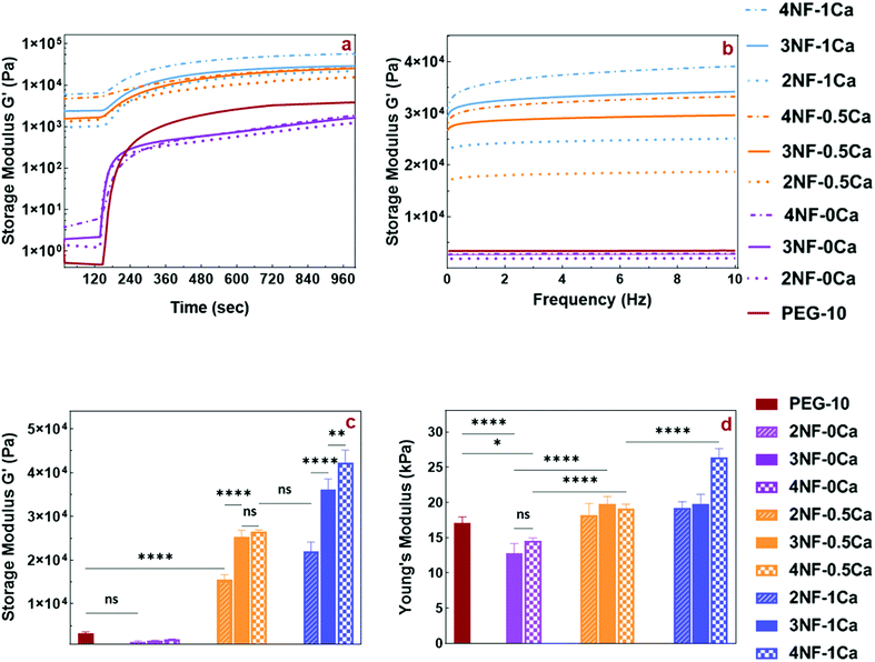
Our ink design involves crosslinking of the PEG star polymer by blue light-initiated thiol–ene chemistry once the precursor mixture has been printed. To understand the speed of this reaction, the gelation kinetics of the inks were measured via in situ rheometry recorded over a time window of 20 min after blue light has been switched on at a time point of 120 s. The gelation curves for all samples showed a fast increase in storage modulus as soon as the light was turned on, reaching a flat linear plateau in less than 3 min (Fig. 4a). Furthermore, inks containing Ca2+ exhibited a storage modulus higher than the loss modulus (Fig. S5a, ESI†) even before light irradiation. This indicates that these inks show more gel-like than solution-like behavior which is due to the ionic gelation with Ca2+. As a control, measurements using PEG-10 solution without CNFs and Ca2+ were performed.
Before photo crosslinking, the samples containing CNFs without any Ca2+ (2NF-0Ca, 3NF-0Ca, and 4NF-0Ca) exhibited a higher storage modulus than PEG-10, in agreement with the observations made from the shear thinning data. Interestingly upon photo crosslinking, these samples appear to have a lower storage modulus than PEG-10, although no significant difference was detected. This indicates that the presence of CNFs without any ionic interactions can impact the crosslinking density of the PEG matrix and decrease the strength of the hydrogel network.
By introducing Ca2+ into the PEG solution, the storage modulus increased as 2NF-0.5Ca, 3NF-0.5Ca, and 4NF-0.5Ca showed almost 4.5-, 7.5-, and 8-times higher storage moduli than PEG-10, respectively. Additionally, increasing the Ca2+ concentration in the precursor mixture improved the storage moduli further, as the storage moduli of 2NF-1Ca, 3NF-1Ca, and 4NF-1Ca were enhanced by almost 6.5, 11, and 13 compared to the PEG-10 sample, respectively. These findings confirmed the reinforcement effect of CNFs and further the positive effect of Ca2+ on the shear strength of PEG-CNF inks. For better comparison, the storage and loss moduli of just one point of time sweep curves (the 12th minute of light exposure) are shown in Fig. 4c and Fig. S5b (ESI†).
These results also revealed how the mechanical properties of hydrogels are easily tunable by altering the CNF content and the crosslinking condition, creating hydrogels with a stiffness range from 1–45 kPa. To date, the narrow range of the mechanical properties of nanocellulose fiber-based inks has limited their application to specific tissue engineering uses such as dermal or cartilage applications.7,12,22 Our approach resulted in tunable CNF based hydrogels, which has great potential to broaden the use of CNFs for different tissue engineering applications such as stem cell differentiation that can be directed by the surface stiffness towards neurogenic (0.1–1 kPa), myogenic (8–17 kPa), and osteogenic (25–40 kPa) cells. Moreover, the interaction with chondrocytes and dermal fibroblasts for cartilage and skin tissue applications can be influenced.7,12,42,43
3.3. Mechanical properties
The mechanical strength of the scaffold plays a significant role in its interaction with cells as it controls cell adhesion, proliferation, migration, differentiation, and apoptosis.44 Thus, the fabrication of scaffolds with desired mechanical properties is essential for biomedical applications. CNFs, modified with carboxyl groups can undergo ionic interactions; however, they can dissociate in high ionic strength aqueous media.22 As discussed above, the complexation between carboxyl groups and Ca2+ is relatively strong, but pH changes, and the presence of other ions or low concentration of the Ca2+ can disrupt the interaction resulting in loss of strength of the physical network. In this study, the double mode crosslinking approach employed to improve the mechanical strength of the printed scaffolds was able to achieve a wide variety of strengths in comparison with previous studies in the literature.7,12,22To compare the mechanical properties of PEG-CNF hydrogels with different ratios of CNFs and Ca2+, the compressive strength and storage modulus were evaluated using compression and frequency sweep tests. The mechanical properties of the formulated hydrogels were evaluated by compression tests on cylindrical samples (Fig. S6, ESI†) after swelling to equilibrium. Fig. 4d shows the correlation of bulk compressive Young's modulus with CNFs and Ca2+ content. The compression test could not be performed on 2NF-0Ca samples because they were not strong enough to be handled for compression testing. 3NF-0Ca and 4NF-0Ca exhibited a lower compressive Young's modulus in comparison to the PEG-10 control. This is in agreement with the trend observed in the storage moduli measured by photo rheology (Fig. 4a and c). It appears that introducing CNFs into PEG without ionic crosslinking lowers the crosslinking efficiency of the network as will be shown by the gel fraction study. This will in turn result in scaffolds with a lower crosslinking density and a reduction in mechanical properties.
The addition of Ca2+ led to increased hydrogel stiffness as the samples 3NF-0.5Ca and 4NF-0.5Ca had noticeably higher compression moduli than 3NF-0Ca and 4NF-0Ca, respectively. Also, increasing the Ca2+ concentration had a positive effect on the hydrogel strength, especially at higher amounts of CNFs, which is evident when comparing the modulus of 4NF-1Ca with 4CNF-0.5Ca (p < 0.0001). This could be attributed to the reinforcement effect of CNFs, which provided the constructive body of the composite ink,44 and assisted by the physical crosslinking with Ca2+. A similar conclusion could be drawn from the frequency test presented in Fig. 4b. The storage moduli gradually increased over the frequency sweep in the presence of CaCl2, confirming that physical crosslinking improves the strength of PEG-CNF hydrogels. These results are also in agreement with data obtained from photo rheology and compression tests in which the samples without any Ca2+ (2NF-0Ca, 3NF-0Ca, and 4NF-0Ca) had much lower storage and Young's moduli than PEG-10 (Fig. 4a and d).
Of note, we found that the Young's modulus of the samples can be simply tuned (∼10–30 kPa) by altering the CNFs (2 to 4 wt%) and Ca2+ (0.5 to 1 molar ratio) content. This range of mechanical properties has not been previously achieved by similar CNF based systems. Markstedt et al. observed that the mechanical properties of CNF-alginate ink, which were developed for cartilage tissue engineering applications, can be varied by changing alginate and CNF concentration (∼23–33 kPa).12 Wallace and co-workers also increased the strength of CNF hydrogels (3–8 kPa) by adding Ca2+, then crosslinking to make the material suitable for skin tissue engineering applications.7 In subsequent work, the group altered the Young's modulus of CNF-gelatin methacrylate (GelMA) (∼2–4.5 kPa) by adjusting GelMA and CNF concentration in order to make the ink formulation suitable for wound healing applications.22 The advantage of our system is that by relatively small changes in CNF content, we achieve a wider range of mechanical strengths in comparison with previous reports. This makes our system highly versatile and allows it to be used in different tissue engineering and biomaterial applications such as cartilage tissue engineering scaffolds with defined interactions with chondrocytes and fibroblasts and as material for wound healing applications as well as stem cell differentiation.7,12,42,43
3.4. Swelling properties
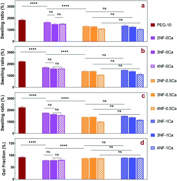
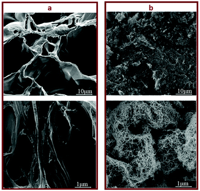
The swelling ratio of a hydrogel is an important parameter in determining the hydrogel capacity for water uptake which determines the diffusion rate for oxygen, the nutrition transfer to cells, and metabolic waste removal. Also, gels with high water content can mimic more closely the extracellular matrix (ECM).10Fig. 5a–c and Fig. S8 (ESI†) show the swelling behavior and % mass loss of all fabricated hydrogels at different time points, respectively. All hydrogels reached equilibrium after 2 h incubation in PBS, increasing substantially in volume (Fig. S7, ESI†). Once equilibrium was reached, the hydrogels retained their shape and no mass loss was observed over the 6 week incubation period. The equilibrated swelling ratio of PEG-10 is significantly higher than all other PEG-CNF hydrogels (p < 0.0001). This is because the CNFs can fill the free space in the PEG hydrogel network and limit the absorption capacity of the PEG matrix.10,45 SEM images confirmed that the PEG hydrogel (Fig. 6a and Fig. S9a, ESI†) had an internal wide-open morphology in comparison with the fine 3D network of cellulose nanofibrils containing PEG-CNFs and Ca2+ (Fig. 6b and Fig. S9b, ESI†). In the samples without Ca2+ (2NF-0Ca, 3NF-0Ca, and 4NF-0Ca), the presence of CNFs didn’t significantly affect the water uptake capacity. On the other hand, Ca2+ ions resulted in reduction in the swelling ratio of the hydrogels. For example 4NF-0.5Ca exhibited a swelling ratio of ∼1000%, in comparison to ∼1600% for 4NF-0Ca. Similar trends were observed for the samples based on 2NF and 3NF. Although samples with higher Ca2+ concentration (4NF-1Ca, 3NF-1Ca, and 2NF-1Ca) displayed a lower swelling ratio, the difference is not significant. The swelling experiments confirm that adding Ca2+ in the formulation results in a more crosslinked network, thus hydrogels cannot expand easily as the network is bound more tightly.46 The gel fractions of the different PEG-CNF hydrogel inks are shown in Fig. 5d. The gel fraction (%) of the samples without any Ca2+ (2NF-0Ca, 3NF-0Ca, and 4NF-0Ca) is lower than those of all the other groups.This indicates that un-crosslinked polymer chains might have leached out of the network. We speculate that the CNFs hinder the crosslinking efficiency of the PEG chains, resulting in a higher % of PEG polymers that are not bound in the network. This would also explain the lower storage moduli and compressive Young's moduli recorded for these samples. All these results taken together highlight the role of the first crosslinking step in improving the stability and mechanical strength of the ink networks.
3.5. Quantitative cell viability SRB assay
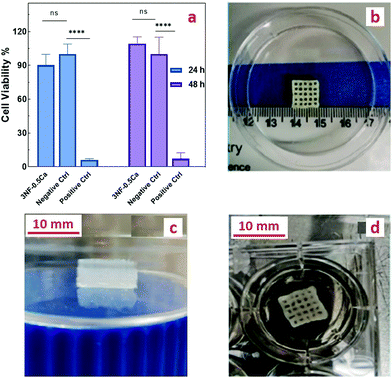
The cytocompatibility of different concentrations of the photoinitiator (FMN) was assessed and no cytotoxicity was observed on L929 cells (Fig. S10, ESI†). To assess the cytocompatibility of the PEG-CNF scaffolds, an indirect cytotoxicity test was performed according to ISO standard 10993-5:2009(E). The cytotoxicity results revealed no indications of adverse effects of the ink. As shown in Fig. 7a, the cell viability percentage of the ink hydrogel and negative control was (90.3 ± 9.5%) and (100 ± 8.8%) after 24 h, and (109.2 ± 6.1%) and (100 ± 14.9%) after 48 h, respectively, so this system can be classified as a noncytotoxic material as a high cell viability was achieved (more than 70%).12 Furthermore, the positive control containing 20% DMSO led to almost complete cell death of (6.2 ± 0.9%) and (7.4± 5.9%) for 24 and 48 h. These results need to be seen in context with the swelling and gel fraction experiments where it was shown that some material will leach out of the hydrogel. However, the small fraction of unbound PEG, CNFs and Ca2+ that was washed out during the swelling experiments has no influence on the cell proliferation.3.6. Printability of the PEG-CNF ink
To optimize the printing parameters, precursor solutions were printed at different speeds (1, 2, 3, and 4 mm s−1) and with different needle sizes (20, 21, 22, and 23 G). Although the smaller nozzle size improves the printability, the nozzle size of 21 G was determined to be optimal because the ink led to clogging of the smaller nozzle sizes. Increased printing speed led to an increased likelihood of the filament to be cut off, so a speed of 2 mm s−1 was found to be the optimal choice. After initial printing tests, it was observed that the inks 3NF-0.5Ca, 4NF-0.5Ca, 3NF-1Ca, and 4NF-1Ca could be printed precisely and with good resolution in comparison with the other mixtures i.e. 2NF-0.5Ca and 2NF-1Ca, which only displayed low resolution after the initial printing. These formulations were able to maintain the printed shape without any collapse. This is an attractive design property that enables the fabrication of millimeter high grid structures that could subsequently be further stabilized under blue light (Fig. S11a and b, ESI†). By comparing the shear strength, compression strength, and swelling, we have found that the difference between the ink properties of 3NF-0.5Ca and other compositions is not significant. This ink formulation was therefore chosen for further scaffold printing and cell study as it also has the lowest concentration of the components among them. The combination of low solid content and high mechanical stability is highly desirable,47,48 as it has been suggested that ink with a high concentration of solid content might restrict the proliferation of cells.2,49We employed our two-step strategy for printing this formulation: the precursor was first physically crosslinked via ionic interactions between CNFs and Ca2+ to obtain the printable gel. After printing, the photo-crosslinking was conducted by exposing the printed structure to blue light. 3D scaffolds that are 10 mm in width, 10 mm in length, and 4 mm in height with a 2 mm filament grid were printed. Fig. 7b shows the top view of the scaffolds after printing and before photo crosslinking. The structure was sufficiently stable after printing, allowing enough time for post photo crosslinking without any collapse. Fig. 7c shows, after 48 h of soaking in the media, the printed structure expanded (∼12 mm × 12 mm × 5.1 mm) due to a high swelling ratio of the hydrogel, but the integrity of the layers and stability of the scaffold remained intact. Of note, the stability of the photo crosslinked printed scaffold was retained following incubation in cell media over the tested period of 2 weeks.
3.7. Cell interactions with hydrogel scaffolds
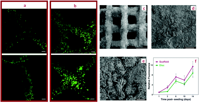
Cell interactions with PEG-CNF hydrogels were studied using L929 fibroblasts. As detailed in the experiment section, L929 cells were seeded on both the disc shaped hydrogel formed in the PDMS mold, and grid scaffolds printed in a 3D printer. Gelatin is commonly used to enhance cell spreading and improve cell attachment,50 therefore 0.5 wt% gelatin was added to the mixture of 3NF-0.5Ca ink. We showed that the gelatin had no effect on the printability and crosslinking of the ink (Fig. S11, ESI†), nor did it alter the shear thinning and gelation kinetics (Fig. S12, ESI†). Furthermore, no significant effect was detected on the physical properties and strength of the hydrogels containing gelatin (Fig. S13, ESI†).Fig. 7d shows the structural integrity of the printed scaffold of 3NF-0.5Ca ink containing 0.5 wt% gelatin after a week post-seeding with L929 cells. The L929 cells attached and proliferated on top of both discs and grid shaped scaffolds over a 14 day period post-seeding according to the Alamar blue cell metabolic assay (Fig. 8f). Both materials, disc and grid structures, displayed a similar trend when monitoring the fluorescence intensity, which translates to a similar relative proliferation rate (Fig. 8f), suggesting that the PEG-CNF printed hydrogel grid enables the same cell proliferation as the bulk disc. The absolute fluorescence intensity results are presented in Fig. S14 (ESI†).
On day 3 and day 14 post-seeding, printed scaffolds were stained with Calcein AM (live cells stained green) and imaged to assess the cell distribution on the scaffold. Visual observation showed a significant increase in the live cell number on day 14 compared to day 3 (Fig. 8a and b) with even cell distribution and uniform cell proliferation over the 3D printed grids. Fig. 8c shows the SEM visualization of the printed scaffold from the top view. The cross-section view of the scaffold is shown in Fig. S15a (ESI†). The printed scaffolds at day 14 of post-seeding were further analyzed using SEM to evaluate the morphology of the cells and their adhesion on the hydrogel scaffold. SEM analysis revealed an elongated cell structure and the even spread of the cells, which indicates good cell attachment and proliferation on the hydrogel surface (Fig. 8d, e and Fig. S15b–d, ESI†).51,52 Thus, cytocompatibility and proliferation activity of L929 fibroblasts on the PEG-CNF scaffolds open up opportunities for their safe applications in tissue engineering applications such as wound healing therapy, as these dermal fibroblasts have a key role in ECM deposition, wound healing, and tissue engineered skin substitution.53
4. Conclusions
In this study, novel dual-crosslinked PEG-CNF hydrogel inks were successfully fabricated via a two-step strategy based initially on ionic interactions to increase the viscosity, followed by a visible light photoreaction to generate a covalent interpenetrating network. The advantage of the binary crosslinking system is the ability to adjust the hydrogel properties towards the 3D printing process. In order to optimize the mixture for extrusion printing, the initial mixture containing CNFs was crosslinked by ionic interactions of TEMPO-oxidized cellulose nanofibers with Ca2+, while PEG star polymers were not yet crosslinked. The viscosity could be adjusted not only by the concentration of Ca2+, but also that of CNFs. The printed scaffolds were able to maintain their structural integrity due to the initial physical crosslinking, but the stability could be further enhanced by post photo crosslinking. Chemical crosslinking of the hydrogel ink was achieved via the thiol–ene photo click reaction of 4-arm PEG-NB. The mechanical properties of PEG-CNF hydrogels were varied according to the ink composition as it dictated the hydrogel crosslinking density. By easily tuning the compositional ratio between CNF and Ca2+, the compressive Young's modulus and shear storage modulus could be well tuned over a wide range (∼10–30 kPa). Furthermore, the composition affected the gel fraction and swelling properties of the hydrogels. The pore size and widths of grids of the printed scaffolds were easily controlled by modifying the printing parameters. The developed ink formulations are noncytotoxic and cytocompatible with L929 fibroblasts, which promotes excellent cell viability and proliferation. This study optimized the ink formulation, which in the future could be explored to embed cells directly into the ink prior to printing the scaffold.In summary, our dual mode crosslinking system is not only versatile and easy to prepare, but it can also be used as an ink for 3D printing of bioscaffolds with tailored viscoelastic and mechanical properties applicable in regenerative medicine.
Conflicts of interest
There are no conflicts to declare.Acknowledgements
MM would like to thank the Australian Government Research Training Program RTP Scholarship. JR-K would like to acknowledge support from the NSW Health Cardiovascular Investigator Development Grant. JR-K was supported by the Heart Foundation of Australia Future Leader Fellowship (101896). MHS would like to thank the Australian Research Council ARC for funding.References
- Y. Rui, X. Gang, M. Shuang-Shuang, Y. Hua-Yu, S. Xin-Ting, S. Wei and M. Yi-Lei, Cancer Biol. Med., 2016, 13, 443 CrossRef PubMed.
- N. S. V. Murphy and A. Atala, Biotechnology, 2014, 32, 773 Search PubMed.
- O. H. S. Ilkhanizadeh and A. Teixeira, Biomaterials, 2007, 28, 3936–3943 CrossRef PubMed.
- J. Groll, J. A. Burdick, D.-W. Cho, B. Derby, M. Gelinsky, S. C. Heilshorn, T. Jüngst, J. Malda, V. A. Mironov, K. Nakayama, A. Ovsianikov, W. Sun, S. Takeuchi, J. J. Yoo and T. B. F. Woodfield, Biofabrication, 2018, 11, 013001 CrossRef CAS PubMed.
- T.-S. Jang, H.-D. Jung, H. M. Pan, W. T. Han, S. Chen and J. Song, Int. J. Bioprint., 2018, 4, 126 Search PubMed.
- R. F. Pereira and P. J. Bártolo, J. Appl. Polym. Sci., 2015, 132, 42458 CrossRef.
- C. Xu, B. Zhang Molino, X. Wang, F. Cheng, W. Xu, P. Molino, M. Bacher, D. Su, T. Rosenau, S. Willför and G. Wallace, J. Mater. Chem. B, 2018, 6, 7066–7075 RSC.
- M. Ozbolat and I. T. Hospodiuk, Biomaterials, 2016, 76, 321–343 CrossRef PubMed.
- T. Gao, G. J. Gillispie, J. S. Copus, A. Kumar PR, Y.-J. Seol, A. Atala, J. J. Yoo and S. J. Lee, Biofabrication, 2018, 10, 034106 CrossRef.
- H. Rastin, R. T. Ormsby, G. J. Atkins and D. Losic, ACS Appl. Bio Mater., 2020, 3, 1815–1826 CrossRef CAS.
- S. J. Bryant and K. S. Anseth, J. Biomed. Mater. Res., 2001, 59, 63–72 CrossRef.
- D. H. Kajsa Markstedt, A. Mantas, I. Tournier, H. Martínez Ávila and P. Gatenholm, Biomacromolecules, 2015, 16, 1489–1496 CrossRef PubMed.
- D. L. K. Benjamin, P. Partlow, C. W. Hanna, J. Rnjak-Kovacina, J. E. Moreau and M. B. Applegate, Adv. Funct. Mater., 2014, 24, 4615–4624 CrossRef PubMed.
- M. K. Shuhei Murayama, F. Ishizuka, K. Takagi, H. Inoda, A. Sano and T. Santa, Ananl. Chem., 2012, 84, 1374–1379 CrossRef PubMed.
- A. M. C. L. C.-J. K. H. A. C. L. Kaplan, J. Phys. Chem. B, 2006, 110, 21630 CrossRef.
- G. Gao, J. H. Lee, J. Jang, D. H. Lee, J.-S. Kong, B. S. Kim, Y.-J. Choi, W. B. Jang, Y. J. Hong, S.-M. Kwon and D.-W. Cho, Adv. Funct. Mater., 2017, 27, 1700798 CrossRef.
- S. Ryu, H. H. Kim, Y. H. Park, C.-C. Lin, I. C. Um and C. S. Ki, J. Mater. Chem. B, 2016, 4, 4574–4584 RSC.
- D. M. Nascimento, Y. L. Nunes, M. C. B. Figueirêdo, H. M. C. De Azeredo, F. A. Aouada, J. P. A. Feitosa, M. F. Rosa and A. Dufresne, Green Chem., 2018, 20, 2428–2448 RSC.
- Y. Y. Khine and M. H. Stenzel, Mater. Horiz., 2020, 7, 1727–1758 RSC.
- D. V. Plackett, K. Letchford, J. K. Jackson and H. M. Burt, Nord. Pulp Pap. Res. J., 2014, 29, 105–118 CrossRef CAS.
- G. Chinga-Carrasco, Biomacromolecules, 2018, 19, 701–711 CrossRef CAS PubMed.
- W. Xu, B. Z. Molino, F. Cheng, P. J. Molino, Z. Yue, D. Su, X. Wang, S. Willför, C. Xu and G. G. Wallace, ACS Appl. Mater. Interfaces, 2019, 11, 8838–8848 CrossRef CAS PubMed.
- R. R. Batchelor, G. Kwandou, P. T. Spicer and M. H. Stenzel, Polym. Chem., 2017, 8, 980–984 RSC.
- S. L. Jacques, Phys. Med. Biol., 2013, 58, 5007–5008 CrossRef.
- R. Huang, E. Choe and D. B. Min, J. Food Sci., 2006, 69, C726–C732 CrossRef.
- Y. Y. Khine, S. Ganda and M. H. Stenzel, ACS Macro Lett., 2018, 7, 412–418 CrossRef CAS.
- D. E. Godar, C. Gurunathan and I. Ilev, Photochem. Photobiol., 2019, 95, 581–586 CrossRef CAS PubMed.
- J. Y. Shin, Y. H. Yeo, J. E. Jeong, S. A. Park and W. H. Park, Carbohydr. Polym., 2020, 238, 116192 CrossRef CAS PubMed.
- S. Schwarz, L. Koerber, A. F. Elsaesser, E. Goldberg-Bockhorn, A. M. Seitz, L. Dürselen, A. Ignatius, P. Walther, R. Breiter and N. Rotter, Tissue Eng., Part A, 2012, 18, 2195–2209 CrossRef CAS PubMed.
- F. Azzam, L. Heux, J. L. Putaux and B. Jean, Biomacromolecules, 2010, 11, 3652–3659 CrossRef CAS PubMed.
- H. Bazin, G. Descotes, A. Bouchu and M. Petit-Ramel, Can. J. Chem., 1995, 73, 1338–1347 CrossRef CAS.
- B. Kutus, X. Gaona, A. Pallagi, I. Pálinkó, M. Altmaier and P. Sipos, Coord. Chem. Rev., 2020, 417, 213337 CrossRef CAS.
- A. L. Rutz, K. E. Hyland, A. E. Jakus, W. R. Burghardt and R. N. Shah, Adv. Mater., 2015, 27, 1607–1614 CrossRef CAS PubMed.
- L. Hubbe, M. A. Tayeb, P. Joyce, M. Tyagi, P. Kehoe, M. Dimic-Misic and K. Pal, BioRes, 2017, 12, 9556–9661 Search PubMed.
- G. Siqueira, D. Kokkinis, R. Libanori, M. K. Hausmann, A. S. Gladman, A. Neels, P. Tingaut, T. Zimmermann, J. A. Lewis and A. R. Studart, Adv. Funct. Mater., 2017, 27, 1604619 CrossRef.
- Y. Jiang, J. Zhou, C. Feng, H. Shi, G. Zhao and Y. Bian, J. Mater. Sci., 2020, 55, 15709–15725 CrossRef CAS.
- A. Smith, P. T. Basu, A. Saha and A. Nelson, Polymer, 2018, 152, 42–50 CrossRef.
- M. Pääkko, M. Ankerfors, H. Kosonen, A. Nykänen, S. Ahola, M. Österberg, J. Ruokolainen, J. Laine, P. T. Larsson, O. Ikkala and T. Lindström, Biomacromolecules, 2007, 8, 1934–1941 CrossRef PubMed.
- S. Kyle, Z. M. Jessop, A. Al-Sabah and I. S. Whitaker, Adv. Healthcare Mater., 2017, 6, 1–16 Search PubMed.
- J. Jia, D. J. Richards, S. Pollard, Y. Tan, J. Rodriguez, R. P. Visconti, T. C. Trusk, M. J. Yost, H. Yao, R. R. Markwald and Y. Mei, Acta Biomater., 2014, 10, 4323–4331 CrossRef CAS PubMed.
- J. T. B. B. Duan, E. Kapetanovic and L. A. Hockaday, Acta Biomater., 2014, 10, 1836–1846 CrossRef PubMed.
- A. J. Engler, S. Sen, H. L. Sweeney and D. E. Discher, Cell, 2006, 126, 677–689 CrossRef CAS PubMed.
- M. Ahearne, Interface Focus, 2014, 4, 20130038 CrossRef PubMed.
- L. D. Muiznieks and F. W. Keeley, Biochim. Biophys. Acta, 2013, 1832, 866–875 CrossRef CAS PubMed.
- S. Shin, S. Park, M. Park, E. Jeong, K. Na, H. J. Youn and J. Hyun, BioResources, 2017, 12, 2941–2954 CrossRef CAS.
- G. Gaharwar, A. K. Rivera, C. Wu, C.-J. Chan and B. K. Schmidt, Mater. Sci. Eng., C, 2013, 33, 1800–1807 CrossRef PubMed.
- J. Liu, G. Chinga-Carrasco, F. Cheng, W. Xu, S. Willför, K. Syverud and C. Xu, Cellulose, 2016, 23, 3129–3143 CrossRef CAS.
- J. Malda, J. Visser, F. P. Melchels, T. Jüngst, W. E. Hennink, W. J. A. Dhert, J. Groll and D. W. Hutmacher, Adv. Mater., 2013, 25, 5011–5028 CrossRef CAS.
- H. Li, C. Tan and L. Li, Mater. Des., 2018, 159, 20–38 CrossRef CAS.
- X. Cui, B. G. Soliman, C. R. Alcala-Orozco, J. Li, M. A. M. Vis, M. Santos, S. G. Wise, R. Levato, J. Malda, T. B. F. Woodfield, J. Rnjak-Kovacina and K. S. Lim, Adv. Healthcare Mater., 2020, 9, 1901667 CrossRef CAS PubMed.
- J. T. Parsons, A. R. Horwitz and M. A. Schwartz, Nat. Rev. Mol. Cell Biol., 2010, 11, 633–643 CrossRef CAS PubMed.
- P. Shi, A. Laude and W. Y. Yeong, J. Biomed. Mater. Res., Part A, 2017, 105, 1009–1018 CrossRef CAS PubMed.
- T. Wong, J. A. McGrath and H. Navsaria, Br. J. Dermatol., 2007, 156, 1149–1155 CrossRef CAS PubMed.
Footnote |
| † Electronic supplementary information (ESI) available. See DOI: 10.1039/d1tb00624j |
| This journal is © The Royal Society of Chemistry 2021 |

