 Open Access Article
High-performance SiO electrodes for lithium-ion batteries: merged effects of a new polyacrylate binder and an electrode-maturation process†
Shogo
Yamazaki
a,
Ryoichi
Tatara
 a,
Hironori
Mizuta
b,
Kei
Kawano
b,
Satoshi
Yasuno
 c and
Shinichi
Komaba
 *a
*a
aDepartment of Applied Chemistry, Tokyo University of Science, 1-3 Kagurazaka, Shinjuku, Tokyo 162-8601, Japan. E-mail: komaba@rs.tus.ac.jp
bFUJIFILM Wako Pure Chemical Co. Ltd, 1633 Oazamatoba, Kawagoe-shi, Saitama 350-1101, Japan
cJapan Synchrotron Radiation Research Institute, 1-1-1 Kouto, Sayo-gun, Hyogo, 679-5198, Japan
First published on 20th February 2023
Abstract
SiO has been extensively studied as a high-capacity negative electrode material for lithium-ion batteries (LIBs). However, battery performance degradation caused by the large volume change during lithiation/delithiation hinders the practical application of SiO. To mitigate volume change degradation, we employed partially neutralized cross-linked sodium polyacrylate (CLPA) binders for fabricating carbon-coated SiO (SiO@C) composite electrodes and evaluated their electrochemical performance. We further synthesized new CLPA-based polymers with different amounts of the functional monomer (flexible additive), which was found to impart flexibility to the SiO composite layer. In addition, we employed “maturation” treatment for the fabricated composite electrode, in which the pre-dried SiO@C composite electrodes with CLPA-based binders on Cu foil were stored in 90% relative humidity for two days before drying. Among the non-matured electrodes, those with a CLPA-based binder with a 20% flexible additive (CLPA-20) exhibited the highest peel strength of 2.37 N cm−1 and a reversible capacity of 1322 mA h g−1 after 90 cycles. The maturation treatment further improved these properties (>5.8 N cm−1 and 1598 mA h g−1). Electron microscopy observations revealed that the dispersion condition of the CLPA binder and conductive carbon additives was clearly improved in the matured electrodes, implying the migration of carbon and binders during the maturation treatment. Matured electrodes not only exhibited enhanced electrochemical properties in Li cells and superior mechanical properties, but also showed better passivation, brought by the uniform and thin binder-coating on the SiO particles, as confirmed by surface analysis of the cycled electrodes.
1. Introduction
Lithium-ion batteries (LIBs) are increasingly used in electric vehicles, large energy storage systems, and portable electronic devices, as crucial power sources.1 Recently, there has been an increase in demand for LIBs with lower cost and higher energy density owing to their large-scale applications.2,3 To tackle this issue, silicon, which is abundant in the earth's crust4 and has a high theoretical capacity through alloying reaction (Li3.75Si: 3579 mA h g−1),5 has been widely studied as a next-generation high-capacity negative electrode among intercalating,6 conversion,7 and alloying materials.8 Si electrodes, however, undergo large volume changes, by factors more than three, during the lithiation/delithiation process. This causes particle pulverization and electrical isolation, resulting in significant capacity degradation during the early stages of charge–discharge cycles.9,10 In general, a solid electrolyte interphase (SEI)11 layer is formed between the negative electrode and non-aqueous electrolyte via electrolyte decomposition during the initial cycles. The SEI layer is known to fail due to continuous volume changes of Si. A new Si surface is formed during every charge–discharge cycle due to particle pulverization; this surface comes in contact with the electrolyte during the lithiation/delithiation process, allowing the electrolyte decomposition reaction to occur continuously, resulting in accumulation of the decomposition products, i.e., a resistive thick layer, on the Si surface.12–16Silicon suboxide (SiOx, x ≈ 1), which is composed of Si and SiO2 nanoparticles and exhibits superior cycling performance compared to elemental Si in Li cells, has attracted attention as a high-capacity negative electrode material because the volume change of SiO is less than that of pure Si.3,17–19 However, the volume change of SiO during lithiation/delithiation (1.6–2 fold)18,20 is significantly greater than that of graphite (1.1 fold) and its electronic conductivity is lower than that of Si.17–19 To overcome these limitations, strategies such as doping to improve conductivity,21,22 surface coating with carbon materials,23,24 and optimization of binders to stabilize the electrode structure,19,25 have been reported.
In a previous paper, we reported that the use of a polyacrylic acid (PAA) binder improves the electrochemical properties of SiO negative electrodes relative to those using the conventional poly(vinylidene difluoride) (PVDF) and carboxymethyl cellulose (CMC) binder.18 Furthermore, the –COONa/COOH ratio was optimized by partially neutralizing PAA with NaOH and the amount of cross-linker was optimized for construction of the Si/graphite composite electrodes.26,27 The aqueous slurry prepared with the optimized binder generates an appropriate porous structure in the composite electrode, which improves its long-term cycling stability by buffering the volume change. Further refinement of the polymer structure and optimization of the electrode preparation process are required for achieving desirable practical performance with LIBs.14,26,27
Roué et al. reported a “maturation” process as a facile and effective method for stabilizing Si-based composite electrodes.28 The process involved storing pre-dried composite electrodes under a humid atmosphere after casting the electrode slurry on Cu foil, and improved the electrochemical performance of the Si electrodes when water-soluble CMC or PAA binders were used.28 They showed that maturation successfully induces binder migration from the surface of the Si particles to the contact points between these particles, strengthening the binding between the particles; simultaneously, the Cu foil slightly corrodes during the maturation process, resulting in the formation of chemical bonds between Cu2+ ions and COO− groups in the binder.28,29 However, the influences of different binders and preparation conditions for the composite electrodes have not yet been fully investigated, because the effects of the maturation process on Si-based negative electrode cycling performance are complex.
In this study, based on our previous works on the partially neutralized cross-linked sodium polyacrylate (CLPA) binder, we synthesized novel CLPA-based polymers via co-polymerization with a different additive monomer. These unique polymers were evaluated as an advanced binder for carbon-coated SiO (SiO@C) composite electrodes. The electrochemical properties of the electrodes were evaluated in a non-aqueous Li cell, and the maturation treatment was employed for further improvement of the electrochemical performance. The synergistic effects between the binder chemical structure and the maturation process were investigated for future strategic development of electrode structures.
2. Experimental section
2.1. Materials
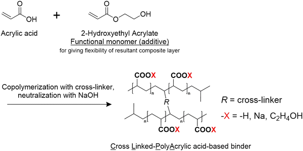
All the CLPA-based binders (Scheme 1) were freshly prepared and supplied by FUJIFILM Wako Pure Chemical Corporation for this study. The composition of the CLPA-based binders is summarized in Table 1. CLPA (standard binder) was synthesized without 2-hydroxymethyl acrylate as shown in Scheme 1. CLAP-20 and CLPA-50 were prepared via co-polymerization with 20 mol% and 50 mol% 2-hydroxymethyl acrylate, respectively, to enhance the flexibility of the resulting composite electrode for facile handling during LIB assembly. SiO@C powder (Fig. S1, ESI† average particle size of 5 μm, OSAKA Titanium Technologies Co., Ltd), acetylene black (AB, Denka Black Li-435, Denka Co. Ltd), poly(vinylidene difluoride) (PVDF, Polysciences, Inc.), and N-methyl-2-pyrrolidinone (NMP, >99.0%, Kanto Chemical Co., Ltd) were used as received. The carbon content in SiO@C (0.97 wt%) was measured using an organic elemental analyzer (vario EL cube, Elementar).2.2. Electrode preparation and characterization
Composite electrodes with a SiO@C![[thin space (1/6-em)]](https://www.rsc.org/images/entities/char_2009.gif) :
:![[thin space (1/6-em)]](https://www.rsc.org/images/entities/char_2009.gif) AB
AB![[thin space (1/6-em)]](https://www.rsc.org/images/entities/char_2009.gif) :
:![[thin space (1/6-em)]](https://www.rsc.org/images/entities/char_2009.gif) binder weight ratio of 80
binder weight ratio of 80![[thin space (1/6-em)]](https://www.rsc.org/images/entities/char_2009.gif) :
:![[thin space (1/6-em)]](https://www.rsc.org/images/entities/char_2009.gif) 10
10![[thin space (1/6-em)]](https://www.rsc.org/images/entities/char_2009.gif) :
:![[thin space (1/6-em)]](https://www.rsc.org/images/entities/char_2009.gif) 10 were prepared. Composite electrodes with a SiO@C
10 were prepared. Composite electrodes with a SiO@C![[thin space (1/6-em)]](https://www.rsc.org/images/entities/char_2009.gif) :
:![[thin space (1/6-em)]](https://www.rsc.org/images/entities/char_2009.gif) AB
AB![[thin space (1/6-em)]](https://www.rsc.org/images/entities/char_2009.gif) :
:![[thin space (1/6-em)]](https://www.rsc.org/images/entities/char_2009.gif) binder weight ratio of 80
binder weight ratio of 80![[thin space (1/6-em)]](https://www.rsc.org/images/entities/char_2009.gif) :
:![[thin space (1/6-em)]](https://www.rsc.org/images/entities/char_2009.gif) 10
10![[thin space (1/6-em)]](https://www.rsc.org/images/entities/char_2009.gif) :
:![[thin space (1/6-em)]](https://www.rsc.org/images/entities/char_2009.gif) 0.5 were prepared for the adhesion strength test. The electrode slurries were prepared by adding an appropriate amount of NMP (for the PVDF binder) or deionized water (for CLPA-based binders) as the solvent and cast on Cu foil. The CLPA-based slurries were cast on UV-ozone-treated Cu foil (17 μm thickness, Hosen Co.), while the PVDF-based slurry was cast on the non-treated one. UV-ozone treatment was conducted using SSP16-110 (Sen Light). The electrodes were dried at 80 °C in ambient air for a few hours and then overnight at 100 °C under vacuum. None of the SiO@C composite electrodes were compressed.
0.5 were prepared for the adhesion strength test. The electrode slurries were prepared by adding an appropriate amount of NMP (for the PVDF binder) or deionized water (for CLPA-based binders) as the solvent and cast on Cu foil. The CLPA-based slurries were cast on UV-ozone-treated Cu foil (17 μm thickness, Hosen Co.), while the PVDF-based slurry was cast on the non-treated one. UV-ozone treatment was conducted using SSP16-110 (Sen Light). The electrodes were dried at 80 °C in ambient air for a few hours and then overnight at 100 °C under vacuum. None of the SiO@C composite electrodes were compressed.
For the maturation treatment, the electrodes were dried at room temperature for approximately 24 h, then stored at room temperature in an environmental test chamber (IW223, Yamato Scientific Co., Ltd) at 90% relative humidity (RH) for two days, and finally vacuum dried at 100 °C. The matured electrodes are denoted as M-CLPA-XX, where M = matured SiO@C composite electrode and XX = flexible additive content. The mass loading of SiO@C in the composite electrodes was in the range of 1.10–1.65 mg cm−2 (corresponds to 1.7–2.6 mA h cm−2 under 1600 mA h g−1 discharge). The sheets of SiO@C composite electrodes were cut into 10 mm-diameter circles for battery testing.
Galvanostatic charge/discharge tests were conducted using R2032-type coin cells (Hosen Co.) assembled in an Ar-filled glove box (Miwa Manufacturing Co., Ltd). Li metal foil (Honjo Chemical Co.) was used as a counter electrode for the half-cell tests (SiO@C‖Li). An electrolyte solution of 1.0 mol dm−3 LiPF6 dissolved in ethylene carbonate (EC) and a dimethyl carbonate (DMC) mixture (volume ratio of EC![[thin space (1/6-em)]](https://www.rsc.org/images/entities/char_2009.gif) :
:![[thin space (1/6-em)]](https://www.rsc.org/images/entities/char_2009.gif) DMC = 1
DMC = 1![[thin space (1/6-em)]](https://www.rsc.org/images/entities/char_2009.gif) :
:![[thin space (1/6-em)]](https://www.rsc.org/images/entities/char_2009.gif) 1, battery grade, Kishida Chemical Co., Ltd) and 2 vol% fluoroethylene carbonate (FEC, Kishida Chemical Co., Ltd) was used for the half-cell tests. A porous polyolefin sheet (Toray Ind. Inc.) was used as a separator. For the cycle test, the initial lithiation (reduction) was conducted in the CC-CV mode, i.e., a constant current (CC) of 25 mA g−1 was applied until 2 mV was reached, followed by the application of a constant voltage (CV) of 2 mV for 12 h. Subsequently, the oxidative delithiation process was carried out at a CC of 25 mA g−1 up to 1.0 V. For the second cycle, the current density was increased to 100 mA g−1 for charging in the voltage range of 0.0–1.0 V without CV application.
1, battery grade, Kishida Chemical Co., Ltd) and 2 vol% fluoroethylene carbonate (FEC, Kishida Chemical Co., Ltd) was used for the half-cell tests. A porous polyolefin sheet (Toray Ind. Inc.) was used as a separator. For the cycle test, the initial lithiation (reduction) was conducted in the CC-CV mode, i.e., a constant current (CC) of 25 mA g−1 was applied until 2 mV was reached, followed by the application of a constant voltage (CV) of 2 mV for 12 h. Subsequently, the oxidative delithiation process was carried out at a CC of 25 mA g−1 up to 1.0 V. For the second cycle, the current density was increased to 100 mA g−1 for charging in the voltage range of 0.0–1.0 V without CV application.
The electrodes were dry-etched by 30 kV Ga-ion milling before and after the electrochemical tests, and the electrode cross-sections were observed using a focused ion beam scanning electron microscope (FIB-SEM, SMF2000, Hitachi). The particle sizes of SiO@C powders and the electrode surface were observed by SEM (JSM-7001F, JEOL, Ltd). A universal tester (STA-1150, A&D Co., Ltd) and double-sided tape (Scotch tape, SPS-12, 3M Japan, Ltd) were used to measure the adhesion strength of the SiO@C composite electrode. The surface components of the fresh and cycled SiO@C composite electrodes were examined by hard X-ray photoelectron spectroscopy (HAXPES). HAXPES was conducted at a high excitation energy of 7938.9 eV using a Scienta Omicron photoelectron energy analyzer, R4000, at BL46XU in SPring-8, Japan. The binding energies in the HAXPES spectra were calibrated and normalized using the C 1s peak of the sp2 carbon of AB at 284.6 eV as a reference.
For post-analysis with X-ray photoelectron spectroscopy (XPS), the charge–discharge current density of the electrodes was changed to accelerate the cycle tests as follows: the initial lithiation was conducted in the CC-CV mode, i.e., a CC of 50 mA g−1 was applied until 2 mV was reached, followed by the application of a CV of 2 mV for 12 h before delithiation. Subsequently, delithiation was carried out at a CC of 50 mA g−1 up to 1.0 V. Then, the current density was increased to 100 mA g−1 for the 2nd–4th and 47th and 48th cycles, and to 200 mA g−1 for the 5th–46th cycles upon charging in the voltage range of 0.0–1.0 V (the voltage was not held constant at 2 mV). The electrodes were removed from the cycled coin cell, washed with DMC (99.5%, battery grade, Kishida Chemical Co., Ltd), and dried at room temperature under ambient pressure in an Ar-filled glovebox. The electrode samples were transferred to a XPS chamber without exposure to air. The electrode samples for SEM analysis were transferred to a SEM chamber with minimal exposure to air.
3. Results and discussion
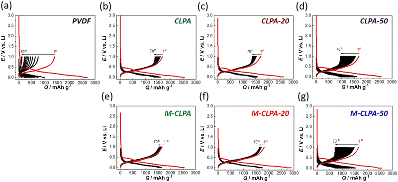
The new polymers, CLPA, CLPA-20, and CLPA-50, were successfully synthesized similar to the previous work.27 Note that CLPA in this study contains a different diallyl cross-linker from the previous one.27 We confirmed that the series of our CLPA polymers are water-soluble and applicable for the aqueous slurry process. We prepared SiO@C composite electrodes using the CLPA polymers to investigate the effect of maturation, which was first demonstrated by Hernandez and co-workers.28Galvanostatic charge–discharge (lithiation–delithiation) curves of the non-matured and matured SiO@C composite electrodes in Li half-cells are compared in Fig. 1. The first discharge curve of SiO@C composite electrodes for all binders exhibits a distinct plateau at approximately 0.45 V. Through galvanostatic electroreduction of the SiO@C composite electrode, SiOx undergoes a conversion reaction during initial charging, and a reversible reaction during subsequent electrooxidation.17 Reversible capacity (approximately 1650 mA h g−1) and the potential curve for SiO electrodes are consistent with the previous report.17
The discharge capacity of the SiO@C composite electrodes with the PVDF binder rapidly decreased with the increasing number of cycles, as shown in Fig. 1(a). Because of the relatively weak binding ability of PVDF and AB powder, the volume change of the SiO@C composite electrode inevitably induced the degradation of the composite electrode structure, leading to rapid capacity loss.30,31 However, this capacity degradation was clearly suppressed when the series of new CLPA-based binders was used (Fig. 1(b)–(d)).
Furthermore, the charge–discharge curves of the matured SiO@C composite electrodes with CLPA and CLPA-20 binders (M-CLPA and M-CLPA-20) showed better capacity retention with almost no increase in polarization over 70 cycles, implying suppressed growth of the interfacial resistance regardless of the repeated volume change during high-capacity lithiation/delithiation (Fig. 1(e) and 1(f)). The charge–discharge curve of the M-CLPA-50 electrode shown in Fig. 1(g) indicates more pronounced capacity degradation after maturation treatment compared to that of a non-matured SiO@C composite electrode with CLPA-50, which is discussed later. The irreversibility in the first cycle, SEI formation, is not significantly different among all the PVDF and CLPA-based electrodes.
Variation of discharge capacity and Coulombic efficiency is plotted as a function of the cycle number in Fig. 2. Among the non-matured electrodes, the discharge capacity of a SiO@C composite electrode with the PVDF binder drastically decreased from 1400 to 96 mA h g−1 during the initial 30 cycles. Using CLPA-based binders in SiO@C composite electrodes successfully leads to higher discharge capacities over 90 cycles. This improvement is due to the improved mechanical strength and coverage of the active materials as we previously described.14,18 The initial discharge capacities of the SiO@C composite electrodes with CLPA-based binders were all approximately 1650 mA h g−1. The high discharge capacity of the electrodes with CLPA-20 was maintained during cycles, and the discharge capacity of the CLPA-20 was slightly higher than that of the electrode with CLPA after the 75th cycle. The capacity retention of the SiO@C composite electrodes with CLPA-20, CLPA, and CLPA-50 in the 90th cycle relative to the 2nd cycle was 87.3%, 83.9%, and 57.6%, respectively. This observation indicates that the co-polymerizable additive of 2-hydroxyethyl acrylate with acrylic acid and cross-linkers imparts stronger binding ability and flexibility to the composite layer, resulting in the suppression of capacity degradation and electrode durability against the volume change. However, using a larger amount of flexible additives (50%) leads to deterioration of capacity retention, possibly caused by insufficient mechanical binding strength of the electrode particulate component with CLPA-50.
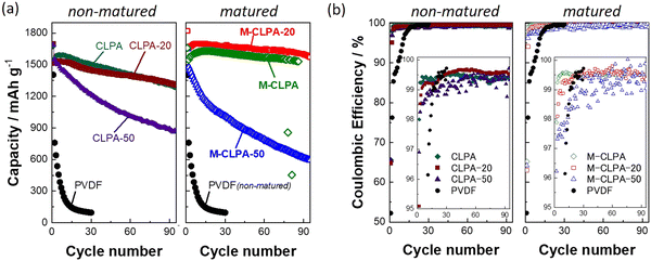 | ||
| Fig. 2 Cycling performance: variations in (a) discharge capacity and (b) Coulombic efficiency of matured and non-matured SiO@C composite electrodes with PVDF and CLPA-based binders in Li half-cells. Charge capacity and comparison with the previous reports are shown in Fig. S5 and Table S1 (ESI†). | ||
As shown in Fig. S2 (ESI†), the viscosities of the 10 wt% binder aqueous solutions are in the order CLPA-20 > CLPA > CLPA-50, which is consistent with the order of long-term cyclabilities (Fig. 2). The higher viscosity of the binder solution allows the preparation of a uniform slurry and better dispersion of electrode materials particles which are presumed to affect cycling performance.27 The maturation treatment resulted in enhanced capacity retention of more than 95% for the M-CLPA and M-CLPA-20 electrodes, whereas the CLPA and CLPA-20 electrodes showed an inferior capacity retention of ca. 83%. In particular, the M-CLPA-20 electrode exhibited a higher reversible capacity of 200–300 mA h g−1 compared to that of the CLPA-20 electrode for 90 cycles. In contrast, the M-CLPA-50 electrode showed an initial discharge capacity of 1652 mA h g−1, which was comparable to that of other electrodes. Its discharge capacity was, however, decayed after the 2nd cycle, providing capacity retention of only 53.5% for the 60th cycle.
The Coulombic efficiencies of the non-matured and matured SiO@C composite electrodes with different CLPA binders are shown in Fig. 2(b). The initial Coulombic efficiencies were 52.2% for the PVDF-based electrodes and approximately 67.5% for the CLPA-based electrodes, regardless of the maturation treatment. The low initial Coulombic efficiency observed in the electrode with the PVDF binder is attributed to the weak binding of powdery electrode materials with PVDF and remarkable electrolyte decomposition owing to the increased contact area between SiO@C and the electrolyte caused by the low coverage with the binder and high porosity of the composite.18 The initial Coulomb efficiency is not affected by the maturation treatment while the previous report with Si electrode showed an improved value,32 possibly because the volume change of SiO is less severe compared with pure Si; thus the amount of electrolyte decomposition during the initial cycle is limited. With CLPA-based binders, the Coulombic efficiency gradually increased during the initial 10 cycles, eventually reaching nearly 99.5%. The average Coulombic efficiencies (2nd–70th cycle) were 99.4% for both the CLPA and CLPA-20 composite electrodes, and 99.5% and 99.4% for the M-CLPA and M-CLPA-20 electrodes, respectively. Thus, there was no significant difference in the average Coulombic efficiencies between the matured and non-matured electrodes with CLPA and CLPA-20. In contrast, the average Coulombic efficiencies of electrodes with CLPA-50 were 98.8% and 99.1% for the matured and non-matured electrodes, respectively, indicating that the maturation process is not effective in this case. The explanation for this observation is discussed later in the XPS section. When the SiO@C composite electrodes with the PVDF binder were matured for three days under 90% RH condition or under the saturated NMP-vapor condition (NMP maturation), the cycling performance was not improved (Fig. S3, ESI†). Matured SiO@C electrodes were also prepared by using styrene-butadiene rubber (SBR) latex/CMC = 1/2 (w/w) as a binder; however, inferior capacity retention values were obtained in comparison with those with CLPA (Fig. S4, ESI†). These results confirm that maturation treatment is an effective strategy for only CLPA and CLPA-20, implying that the number of carboxyl groups in the binder are likely to be one of key factors for demonstrating SiO-based electrode improvement. Previous reports also indicate that the presence of carboxyl groups is effective in improving the cycling performance through maturation treatment, possibly due to copper (current collector) corrosion and physical cross-linking of the carboxylic binder by Cu2+.29,32 This result agrees with the fact that the maturation treatment is not effective for PVdF-based, carboxyl group-free composite electrodes.
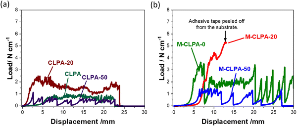
The peel strength of Si-based electrodes has a significant impact on the cycling performance;15,33 therefore, 90° peel tests were conducted for the SiO@C composite electrodes with CLPA-based binders. Fig. 3 shows the load–displacement curve of the 90° peel test, and the peel strength and the calculated average load obtained from the load–displacement curve of each SiO@C composite electrode are summarized in Table 2. The M-CLPA-20 electrode could not be evaluated accurately because the adhesive tape peeled off before the composite layer peeled off from the current collector, indicating a quite high adhesive strength of the M-CLPA-20 electrode. Among the non-matured electrodes, the CLPA-20 composite electrode showed the highest peel strength and average load. The average load for SiO@C composite electrodes with CLPA-based binders decreased in the order of CLPA-20 (1.67 N cm−1) > CLPA (0.80 N cm−1) > CLPA-50 (0.48 N cm−1). This order is consistent with the cycling performance (Fig. 2), suggesting that the adhesive strength of the SiO@C composite electrode is important to improve capacity retention, as described in other studies.34–36 The SiO@C composite electrodes with CLPA-20 showed a higher average load than those with CLPA and CLPA-50, supporting that the optimal amount of 2-hydroxyethyl acrylate for the highly durable SiO@C composite electrode is approximately 20%.
| Electrodes | CLPA | CLPA-20 | CLPA-50 | M-CLPA | M-CLPA-20 | M-CLPA-50 |
|---|---|---|---|---|---|---|
| Peel strength (N cm−1) | 0.70(2) | 2.37(13) | 1.14(1) | 3.13(39) | >5.8 | 1.37(1) |
| Average load (N cm−1) | 0.80(9) | 1.67(11) | 0.48(12) | 1.21(44) | >7.50 | 0.58(4) |
Fig. 3(b) shows the load–displacement curves of the matured electrodes. It is obvious that the adhesive strength of the SiO@C composite electrode with all the CLPA-based binders increased upon the maturation treatment. According to the previous report,37 binder species gradually migrate to the surface of the composite electrode during the drying process due to capillary transport of the binder and active material, resulting in a “binder gradient” in the composite electrode. Through the maturation treatment, the binder migrates again from the surface of the Si particles to the contact points between those particles, increasing the adhesion between the particles.28 Because of the suitable migration of CLPA and CLPA-20 by the maturation treatment, the M-CLPA-20 electrode exhibited a peel strength of 5.8 N cm−1 or higher (Fig. 3(b), accurate measurement was not possible). In contrast, Fig. 3 confirms that the M-CLPA-50 electrode shows less adhesion strength compared with CLPA-50, meaning that the maturation is not effective for CLPA-50 polymers. This suggests that the optimal content of carboxylic monomer is a crucial factor for matured CLPA-based composite electrodes.
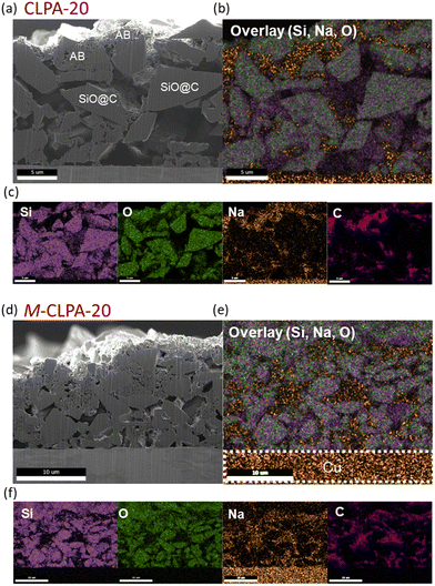
Because the maturation process greatly improved the mechanical properties of the CLPA-20 electrode, cross-sectional SEM images were acquired to verify the migration of the binder during the maturation treatment. Cross-sectional SEM images and energy-dispersive X-ray spectroscopy (EDS) mapping of the non-matured and matured SiO@C composite electrodes with CLPA-20 before and after cycling are shown in Fig. 4. The porosity of the SiO@C composite electrodes with CLPA-20 and the M-CLPA-20 electrode (Fig. 4(a)–(d)) was 23.3% and 14.6%, respectively, indicating that the maturation treatment altered the uniformity and packing condition of the electrode components. EDS mapping of Si and O revealed no significant difference in the dispersion of SiO in the SiO@C composite electrodes with CLPA-20 and the M-CLPA-20 electrode. In contrast, Na from the CLPA binder was distributed mostly on the surface of the SiO@C composite electrode with CLPA-20, whereas it was widely distributed in the interior of the M-CLPA-20 electrode. The Na signal in EDS mapping overlapped with the carbon distribution of the AB carbon particles. This is in agreement with the fact that heavy active materials precipitate during the drying process of the composite electrode, while conductive carbon and the binder migrate close to the electrode surface.37,38 This uniform binder distribution obtained through maturation treatment improved the cycling performance and adhesion strength, as shown in Fig. 2 and 3, respectively.
Fig. 5 displays surface SEM images showing that the non-matured and matured SiO@C composite electrodes have similar smooth morphologies. The cycled non-matured electrode damaged by changing into a rough and porous surface, whereas the matured electrode maintained a dense surface after 30 cycles. This difference in morphology change indicated that the maturation treatment efficiently preserves the electrode structure after repeated high-capacity lithiation cycling. Note that cracks, which probably formed during the drying process after washing with a DMC solvent prior to SEM observation, appeared in both the cycled electrodes.39
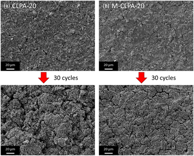 | ||
| Fig. 5 SEM images of the surface for the pristine and cycled (a) non-matured and (b) matured SiO@C composite electrodes with CLPA-20 after 30 cycles. | ||
To analyze the electrolyte decomposition products deposited on the SiO@C composite electrode surface during the charge–discharge tests, HAXPES with synchrotron X-ray was employed for the electrodes cycled for 0 (pristine electrode), 5, and 48 cycles. Although lab-scale XPS using conventional soft X-ray can help detect photoelectrons emitted from the outer-surface to a depth of a few nm, HAXPES measurements, which use hard X-rays, can provide inner-surface information to a depth of >10 nm from the surface.40 For comparison, raw data of photoelectron spectra were processed using binding-energy calibration and peak-intensity normalization with respect to the C 1s signal of sp2 C (284.6 eV).41
Fig. 6 shows the Si 1s, C 1s, and F 1s HAXPES spectra of the non-matured and matured SiO@C composite electrodes with PVDF, CLPA-20, and CLPA-50. When PVDF was used as a binder, Si (1839.5 eV) and SiO2 (1844.5 eV) peaks of the active material distinctly appeared in the Si 1s spectrum of the pristine electrode;41 however, no silicon was detected for the PVDF electrode after 48 cycles. After the charge–discharge tests, an increase in the intensities of the peaks at (i) 286.3 eV (–O–C(![[double bond, length as m-dash]](https://www.rsc.org/images/entities/char_e001.gif) O)–
O)–![[R with combining low line]](https://www.rsc.org/images/entities/char_0052_0332.gif) )16 and 288.5 eV (–
)16 and 288.5 eV (–![[C with combining low line]](https://www.rsc.org/images/entities/char_0043_0332.gif) (
(![[double bond, length as m-dash]](https://www.rsc.org/images/entities/char_e001.gif) O)–O–)42 in the C 1s spectrum, attributable to the solvent decomposition products and (ii) 534.5 eV in the F 1s spectrum, attributable to LixPOyFz formed due to the reaction of POF3 with carbonate solvents such as EC and DMC (POF3 + 2xe− + 2xLi+ → xLiF + LixPF3−x O) was observed. In addition, POF3 (LiPF6 + H2O → LiF + 2HF + POF3) can be formed from the reaction of LiPF6 with traces of water in the electrolyte.43 Thus, EC and DMC decomposition products were deposited on the surface of SiO@C, which suggests that SiO@C was not completely covered with PVDF binder species, unlike PAA-based binders.44 We believe, therefore, that the decomposition reaction at the SiO@C/electrolyte interface occurs continuously during cycling,16 confirming the lower efficiency of the PVDF electrode, as mentioned in Fig. 2(b).
O)–O–)42 in the C 1s spectrum, attributable to the solvent decomposition products and (ii) 534.5 eV in the F 1s spectrum, attributable to LixPOyFz formed due to the reaction of POF3 with carbonate solvents such as EC and DMC (POF3 + 2xe− + 2xLi+ → xLiF + LixPF3−x O) was observed. In addition, POF3 (LiPF6 + H2O → LiF + 2HF + POF3) can be formed from the reaction of LiPF6 with traces of water in the electrolyte.43 Thus, EC and DMC decomposition products were deposited on the surface of SiO@C, which suggests that SiO@C was not completely covered with PVDF binder species, unlike PAA-based binders.44 We believe, therefore, that the decomposition reaction at the SiO@C/electrolyte interface occurs continuously during cycling,16 confirming the lower efficiency of the PVDF electrode, as mentioned in Fig. 2(b).
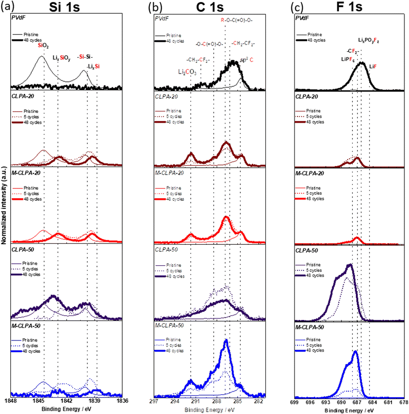 | ||
| Fig. 6 (a) Si 1s, (b) C 1s, and (c) F 1s HAXPES spectra of the non-matured and matured SiO@C composite electrodes with different binders before cycling, after 5 cycles, and after 48 cycles. | ||
In the Si 1s spectrum of the non-matured pristine SiO@C composite electrode with CLPA-20, the relative peak intensity of Si normalized to the sp2 C is lower than that ofthe pristine SiO@C composite electrode with PVDF, which is attributed to the more uniform coverage of SiO@C with CLPA-20 than with PVDF, that is, the thin layer of the CLPA-20 binder on SiO@C particles can act as a “pre-formed SEI” to suppress the initial irreversible decomposition.16 After 48 cycles, peaks at 1843 eV (LixSiOy) and 1838.5 eV (LixSi) attributed to lithiated SiO@C were observed.16 Actually, although peaks corresponding to R–O–C(![[double bond, length as m-dash]](https://www.rsc.org/images/entities/char_e001.gif) O)–O– and O–
O)–O– and O–![[C with combining low line]](https://www.rsc.org/images/entities/char_0043_0332.gif) (
(![[double bond, length as m-dash]](https://www.rsc.org/images/entities/char_e001.gif) O)–O– shown in the C 1s spectra, due to the presence of electrolyte decomposition products, appeared, their intensity was lower than that with the PVDF electrode. Thus, we hypothesize that the high adhesive strength of CLPA-20 provides higher structural stability and superior SEI passivation of the SiO@C composite electrode during battery cycling, suppressing continuous electrolyte decomposition and growth of a thick surface layer at the SiO/electrolyte interface, because of the high Coulombic efficiency for CLPA-20 (Fig. 2(b)). Superior passivation by CLPA-20 compared with CLPA-50 could originate from the higher mechanical strength (Fig. 3) of CLPA-20-based electrodes, which leads to stable coverage of the active material surface over cycling.
O)–O– shown in the C 1s spectra, due to the presence of electrolyte decomposition products, appeared, their intensity was lower than that with the PVDF electrode. Thus, we hypothesize that the high adhesive strength of CLPA-20 provides higher structural stability and superior SEI passivation of the SiO@C composite electrode during battery cycling, suppressing continuous electrolyte decomposition and growth of a thick surface layer at the SiO/electrolyte interface, because of the high Coulombic efficiency for CLPA-20 (Fig. 2(b)). Superior passivation by CLPA-20 compared with CLPA-50 could originate from the higher mechanical strength (Fig. 3) of CLPA-20-based electrodes, which leads to stable coverage of the active material surface over cycling.
It is worth noting that no significant changes in the C 1s and F 1s spectra were found between the matured SiO@C composite electrodes with CLPA-20 between the 5th and 48th cycles. This shows the suppression of the electrolyte decomposition during cycling with the CLPA-20 binder. The cross-sectional SEM image and EDS mapping of the cycled electrode confirm that the non-matured SiO@C composite electrode is partially detached from the current collector (Fig. S6, ESI†), and the fluorine signal due to the formation of the electrolyte decomposition product was confirmed in the whole composite layer. For the matured electrodes, however, such detachment of the composite layer was not observed and a decrease in the amount of fluorine was detected (Fig. S6 and S7, ESI†). EDS spectra (Fig. S7, ESI†) of the matured electrodes did not show any phosphorus signals due to the decomposition of the LiPF6-based electrolyte. This observation indicates that the rigid and stable electrode structure suppresses excessive electrolyte decomposition not only on the surface but also inside the composite electrode. In the F 1s spectrum (Fig. 6(c)), the peak at 685 eV, attributed to LiF43,45 due to the decomposition of the electrolyte salt (LiPF6) and FEC was not observed. Moreover, photoelectrons were detected at binding energies higher than 690 eV, but despite several attempts at peak indexing, we were unable to identify any reasonable species. It is known that inorganic products such as LiF and LixPOyFz which are the decomposition products of LiPF6 and FEC exist on the surface near the active material. Organic materials such as polycarbonate, which is a decomposition by-product of the electrolyte solvent, further cover the inorganic species (LiF and LixPOyFz) after cycling.46,47 Therefore, we hypothesize that organic and inorganic decomposition products exist in electron-insulating deposits on the surface, resulting in the formation of a charge-up surface by photoelectron emission and peak-shift toward higher energy. Thus, the binding energy of the F 1s spectrum is possibly shifted by a few eV more than that of the C 1s spectrum used for calibration, resulting in the appearance of unidentified peaks in the 690–695 eV range. In the HAXPES spectra of LiF and LiPF6 composites mixed with AB and polyvinyl alcohol binders on Cu foil (Fig. S8, ESI†), a broad peak shifted to higher binding energies than the reference peak energy,43,48 indicating that the F 1s spectrum may be strongly influenced by the charge-up effect. As seen in the P 1s spectra (Fig. S9 and S12, ESI†), the inorganic species, such as LiPF6 (2152 eV) and LixPOyFz (2150 eV)49,50 were also strongly affected by the charge-up effect, consistent with F 1s spectra.
In the Si 1s spectrum of the non-matured SiO@C composite electrode with CLPA-50, SiO2 and Si peaks were observed even after 48 cycles; however, they were absent for the matured electrodes. As shown in Fig. 3, the non-matured SiO@C composite electrode with CLPA-50 has low peel strength, which allows the SiO@C particles to be electrically isolated due to the volume change of SiO@C during subsequent cycles, resulting in unreacted SiO@C.18 However, because of the higher peel strength of the matured electrode, the SiO@C particles were not electronically isolated, and the reaction proceeded uniformly throughout the electrode, presumably resulting in the absence of unreacted SiO@C on the electrode surface. In the C 1s spectrum of the non-matured SiO@C composite electrode with CLPA-50, the peak intensities of the decomposition products of the electrolyte solvent (![[R with combining low line]](https://www.rsc.org/images/entities/char_0052_0332.gif) –O–C(
–O–C(![[double bond, length as m-dash]](https://www.rsc.org/images/entities/char_e001.gif) O)–O– and O–
O)–O– and O–![[C with combining low line]](https://www.rsc.org/images/entities/char_0043_0332.gif) (
(![[double bond, length as m-dash]](https://www.rsc.org/images/entities/char_e001.gif) O)–O–) increased after 5 cycles (in relation to those of the pristine electrode); however, the peak intensities decreased after 48 cycles (relative to that of the 5th cycle).
O)–O–) increased after 5 cycles (in relation to those of the pristine electrode); however, the peak intensities decreased after 48 cycles (relative to that of the 5th cycle).
Similar results were obtained from the P 1s and O 1s spectra (Fig. S9, ESI†). The peak intensity of R–O–CO2 (533 eV),16 attributed to the decomposition products of the electrolyte solvent, in the O 1s spectrum, and the peak intensities in the P 1s spectrum were lower for electrodes with CLPA-20 than with CLPA-50. In particular, the O 1s and P 1s spectra of the matured electrode with CLPA-20 showed almost no change between the 5th and 48th cycles, which is consistent with the results shown in Fig. 6. Notably, the spectrum of the electrode soaked in the electrolyte is similar to that of the pristine electrode (Fig. S10, ESI†), indicating that growth of the electrolyte decomposition layer was successfully suppressed at the M-CLPA-20 electrode.
Fig. 7 shows the relative atomic ratios of elements on the electrode surface estimated from the HAXPES spectra. In electrodes with CLPA-20, CLPA-50, and M-CLPA-50, the atomic ratio of elements on the surface changed remarkably with the number of cycles, indicating continuous electrolyte decomposition and degradation of the electrode architecture. In contrast, the atomic ratio was unchanged for the M-CLPA-20 electrode from the 5th to the 48th cycle. This fact indicates that the SEI formed during the early stages of cycling was retained, even though higher capacity cycling should be accompanied by larger volume change caused by reversible lithiation of SiO. This means that the maturation process allows for the effective passivation of the electrode surface and enhancement of mechanical strength of the SiO@C and AB powdery mixture.
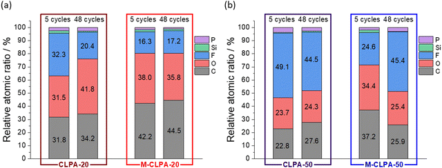 | ||
| Fig. 7 Atomic ratio of elements estimated from the HAXPES peak intensity relative to that of sp2 carbon (Fig. 6 and Fig. S9, ESI†) of non-matured and matured SiO@C composite electrodes with (a) CLPA-20 and (b) CLPA-50. | ||
As mentioned above, the XPS results indicate that, with PVDF, the electrolyte decomposition products continuously accumulated on the electrode surface during cycling due to the insufficient coverage of the SiO@C composite electrode. When CLPA-50 is used, the higher content of 2-hydroxyethyl acrylate provides low mechanical stability, resulting in degradation of the electrode structure and continuous electrolyte decomposition due to continuous volume change of SiO@C. CLPA-20 provides higher adhesion and reversibly adjusts to the volume change during the lithiation and delithiation process of SiO@C. Thus, the electrode structure was preserved when CLPA-20 was used, and the continuous electrolyte decomposition was completely suppressed over 48 cycles, improving the electrochemical performance. Moreover, in the case of the M-CLPA-20 electrode, the dispersibility of the binder changes and the adhesion between particles further improves, thereby contributing to the stabilization of the electrode structure. The SEI formed during the early stages of cycling is maintained during long-term cycling, without undergoing rupture or dissolution. We developed a new cross-linked acrylic copolymer via NaOH partial neutralization, and proved the unique merging effect of the CLPA-20 binder and maturation treatment on high performance SiO@C negative electrodes for practical LIBs.
4. Conclusion
Partially neutralized cross-linked sodium polyacrylate binders prepared via co-polymerization were developed and employed for the first time in the fabrication of high-capacity SiO@C composite electrodes. Introducing 20% hydroxyethyl acrylate monomers in the CLPA improved the mechanical properties of the composite electrode and improved its cycling performance because the volume change was successfully accommodated during reversible lithiation of SiO@C. Furthermore, the maturation treatment resulted in better durability and formation of a suitable passivation layer, as the binder and conductive carbon were uniformly dispersed on the composite electrode surface. This further enhanced the cycling performance of SiO as an active material for LIBs. This study provides a merged and new approach to improve the mechanical performance of composite electrodes and demonstrates the effectiveness of the maturation process in the fabrication of Si-based negative electrodes for LIBs.Author contributions
Shogo Yamazaki: writing – original draft, investigation, visualization. Ryoichi Tatara: writing – review & editing, investigation, visualization. Hironori Mizuta: writing – review & editing, resources. Kei Kawano: writing – review & editing, resources. Satoshi Yasuno: writing – review & editing, investigation. Shinichi Komaba; writing – review & editing, conceptualization, supervision.Conflicts of interest
There are no conflicts to declare.Acknowledgements
The synchrotron radiation experiments were carried out at BL46XU of SPring-8 with the approval of the Japan Synchrotron Radiation Research Institute (JASRI) under proposal numbers 2021B1874, 2022A1657 and 2022B1838. The authors at TUS thank Keisuke Shinoda for his assistance with the FIB-SEM measurements at the National Institute for Materials Science (NIMS) Battery Research Platform under the JST grant number JPMJPF2016.References
- M. Armand and J.-M. Tarascon, Nature, 2008, 451, 652–657 CrossRef CAS PubMed.
- X. Zuo, J. Zhu, P. Müller-Buschbaum and Y.-J. Cheng, Nano Energy, 2017, 31, 113–143 CrossRef CAS.
- C.-M. Park, J.-H. Kim, H. Kim and H.-J. Sohn, Chem. Soc. Rev., 2010, 39, 3115–3141 RSC.
- M. T. McDowell, S. W. Lee, W. D. Nix and Y. Cui, Adv. Mater., 2013, 25, 4966–4985 CrossRef CAS PubMed.
- K. Feng, M. Li, W. Liu, A. G. Kashkooli, X. Xiao, M. Cai and Z. Chen, Small, 2018, 14, 1702737 CrossRef PubMed.
- T.-F. Yi, J. Mei, P.-P. Peng and S. Luo, Composites, Part B, 2019, 167, 566–572 CrossRef CAS.
- Z.-L. Cai, Z.-L. Peng, M.-Q. Wang, J.-Y. Wu, H.-S. Fan and Y.-F. Zhang, Rare Met., 2021, 40, 1451–1458 CrossRef CAS.
- G.-L. Xu, Y.-D. Gong, C. Miao, Q. Wang, S.-Q. Nie, Y. Xin, M.-Y. Wen, J. Liu and W. Xiao, Rare Met., 2022, 41, 3421–3431 CrossRef CAS.
- B. Key, R. Bhattacharyya, M. Morcrette, V. Seznéc, J.-M. Tarascon and C. P. Grey, J. Am. Chem. Soc., 2009, 131, 9239–9249 CrossRef CAS PubMed.
- H. Zhang and P. V. Braun, Nano Lett., 2012, 12, 2778–2783 CrossRef CAS PubMed.
- S. Menkin, D. Golodnitsky and E. Peled, Electrochem. Commun., 2009, 11, 1789–1791 CrossRef CAS.
- Y. Oumellal, N. Delpuech, D. Mazouzi, N. Dupré, J. Gaubicher, P. Moreau, P. Soudan, B. Lestriez and D. Guyomard, J. Mater. Chem., 2011, 21, 6201 RSC.
- C. C. Nguyen and S.-W. Song, Electrochim. Acta, 2010, 55, 3026–3033 CrossRef CAS.
- Z.-J. Han, N. Yabuuchi, K. Shimomura, M. Murase, H. Yui and S. Komaba, Energy Environ. Sci., 2012, 5, 9014–9020 RSC.
- M. Murase, N. Yabuuchi, Z.-J. Han, J.-Y. Son, Y.-T. Cui, H. Oji and S. Komaba, ChemSusChem, 2012, 5, 2307–2311 CrossRef CAS PubMed.
- T. Mochizuki, S. Aoki, T. Horiba, M. Schulz-Dobrick, Z.-J. Han, S. Fukuyama, H. Oji, S. Yasuno and S. Komaba, ACS Sustainable Chem. Eng., 2017, 5, 6343–6355 CrossRef CAS.
- M. Yamada, A. Inaba, A. Ueda, K. Matsumoto, T. Iwasaki and T. Ohzuku, J. Electrochem. Soc., 2012, 159, A1630–A1635 CrossRef CAS.
- S. Komaba, K. Shimomura, N. Yabuuchi, T. Ozeki, H. Yui and K. Konno, J. Phys. Chem. C, 2011, 115, 13487–13495 CrossRef CAS.
- S. Kuang, D. Xu, W. Chen, X. Huang, L. Sun, X. Cai and X. Yu, Appl. Surf. Sci., 2020, 521, 146497 CrossRef CAS.
- S. C. Jung, H.-J. Kim, J.-H. Kim and Y.-K. Han, J. Phys. Chem. C, 2016, 120, 886–892 CrossRef CAS.
- M. Peng, Y. Qiu, M. Zhang, Y. Xu, L. Yi and K. Liang, Appl. Surf. Sci., 2020, 507, 145060 CrossRef CAS.
- X.-D. Li, Y.-M. Zhao, Y.-F. Tian, Z.-Y. Lu, M. Fan, X.-S. Zhang, H. Tian, Q. Xu, H.-L. Li and Y.-G. Guo, ACS Appl. Mater. Interfaces, 2022, 14, 27854–27860 CrossRef CAS PubMed.
- Z. Li, Q. He, L. He, P. Hu, W. Li, H. Yan, X. Peng, C. Huang and L. Mai, J. Mater. Chem. A, 2017, 5, 4183–4189 RSC.
- T. Hirose, M. Morishita, H. Yoshitake and T. Sakai, Solid State Ionics, 2017, 304, 1–6 CrossRef CAS.
- H. Xiao, J. Qiu, S. Wu, L. Xie, W. Zhou, X. Wei, K. N. Hui, M. Zhang and Z. Lin, ACS Appl. Mater. Interfaces, 2022, 14, 18625–18633 CrossRef CAS PubMed.
- Z.-J. Han, K. Yamagiwa, N. Yabuuchi, J.-Y. Son, Y.-T. Cui, H. Oji, A. Kogure, T. Harada, S. Ishikawa, Y. Aoki and S. Komaba, Phys. Chem. Chem. Phys., 2015, 17, 3783–3795 RSC.
- S. Aoki, Z.-J. Han, K. Yamagiwa, N. Yabuuchi, M. Murase, K. Okamoto, T. Kiyosu, M. Satoh and S. Komaba, J. Electrochem. Soc., 2015, 162, A2245–A2249 CrossRef CAS.
- C. R. Hernandez, A. Etiemble, T. Douillard, D. Mazouzi, Z. Karkar, E. Maire, D. Guyomard, B. Lestriez and L. Roué, Adv. Energy Mater., 2018, 8, 1701787 CrossRef.
- V. Vanpeene, J. Villanova, A. King, B. Lestriez, E. Maire and L. Roué, Adv. Energy Mater., 2019, 9, 1803947 CrossRef.
- S. Choi, T. Kwon, A. Coskun and J. W. Choi, Science, 2017, 357, 279–283 CrossRef CAS PubMed.
- L. Deng, Y. Zheng, X. Zheng, T. Or, Q. Ma, L. Qian, Y. Deng, A. Yu, J. Li and Z. Chen, Adv. Energy Mater., 2022, 12, 2200850 CrossRef CAS.
- C. R. Hernandez, A. Etiemble, T. Douillard, D. Mazouzi, Z. Karkar, E. Maire, D. Guyomard, B. Lestriez and L. Roué, Adv. Energy Mater., 2018, 8, 1701787 CrossRef.
- C. Chen, F. Chen, L. Liu, J. Zhao and F. Wang, Electrochim. Acta, 2019, 326, 134964 CrossRef CAS.
- X. Zhu, F. Zhang, L. Zhang, L. Zhang, Y. Song, T. Jiang, S. Sayed, C. Lu, X. Wang, J. Sun and Z. Liu, Adv. Funct. Mater., 2018, 28, 1705015 CrossRef.
- S. Sun, D. He, P. Li, Y. Liu, Q. Wan, Q. Tan, Z. Liu, F. An, G. Gong and X. Qu, J. Power Sources, 2020, 454, 227907 CrossRef CAS.
- Z. Chen, H. Zhang, T. Dong, P. Mu, X. Rong and Z. Li, ACS Appl. Mater. Interfaces, 2020, 12, 47164–47180 CrossRef CAS PubMed.
- J. Kumberg, M. Müller, R. Diehm, S. Spiegel, C. Wachsmann, W. Bauer, P. Scharfer and W. Schabel, Energy Technol., 2019, 7, 1900722 CrossRef CAS.
- K. Y. Cho, Y. I. Kwon, J. R. Youn and Y. S. Song, Analyst, 2013, 138, 2044 RSC.
- P. G. Kitz, M. J. Lacey, P. Novák and E. J. Berg, J. Power Sources, 2020, 477, 228567 CrossRef CAS.
- B. Philippe, R. Dedryvère, J. Allouche, F. Lindgren, M. Gorgoi, H. Rensmo, D. Gonbeau and K. Edström, Chem. Mater., 2012, 24, 1107–1115 CrossRef CAS.
- N. Yabuuchi, K. Shimomura, Y. Shimbe, T. Ozeki, J.-Y. Son, H. Oji, Y. Katayama, T. Miura and S. Komaba, Adv. Energy Mater., 2011, 1, 759–765 CrossRef CAS.
- T. Hosaka, T. Matsuyama, K. Kubota, S. Yasuno and S. Komaba, ACS Appl. Mater. Interfaces, 2020, 12, 34873–34881 CrossRef CAS PubMed.
- V. Etacheri, O. Haik, Y. Goffer, G. A. Roberts, I. C. Stefan, R. Fasching and D. Aurbach, Langmuir, 2012, 28, 965–976 CrossRef CAS PubMed.
- S. Komaba, T. Ozeki and K. Okushi, J. Power Sources, 2009, 189, 197–203 CrossRef CAS.
- K. Schroder, J. Alvarado, T. A. Yersak, J. Li, N. Dudney, L. J. Webb, Y. S. Meng and K. J. Stevenson, Chem. Mater., 2015, 27, 5531–5542 CrossRef CAS.
- C. Xu, F. Lindgren, B. Philippe, M. Gorgoi, F. Björefors, K. Edström and T. Gustafsson, Chem. Mater., 2015, 27, 2591–2599 CrossRef CAS.
- K. W. Schroder, A. G. Dylla, S. J. Harris, L. J. Webb and K. J. Stevenson, ACS Appl. Mater. Interfaces, 2014, 6, 21510–21524 CrossRef CAS PubMed.
- L. Caracciolo, L. Madec and H. Martinez, ACS Appl. Energy Mater., 2021, 4, 11693–11699 CrossRef CAS.
- A. Oishi, R. Tatara, E. Togo, H. Inoue, S. Yasuno and S. Komaba, ACS Appl. Mater. Interfaces, 2022, 14, 51808–51818 CrossRef CAS PubMed.
- R. Tatara, T. Umezawa, K. Kubota, T. Horiba, R. Takaishi, K. Hida, T. Matsuyama, S. Yasuno and S. Komaba, ChemElectroChem, 2021, 8, 4345–4352 CrossRef CAS.
Footnote |
| † Electronic supplementary information (ESI) available. See DOI: https://doi.org/10.1039/d2ma01093c |
| This journal is © The Royal Society of Chemistry 2023 |

